EP2128010A1 - Throttle device - Google Patents
Throttle device Download PDFInfo
- Publication number
- EP2128010A1 EP2128010A1 EP09155225A EP09155225A EP2128010A1 EP 2128010 A1 EP2128010 A1 EP 2128010A1 EP 09155225 A EP09155225 A EP 09155225A EP 09155225 A EP09155225 A EP 09155225A EP 2128010 A1 EP2128010 A1 EP 2128010A1
- Authority
- EP
- European Patent Office
- Prior art keywords
- throttle
- sensor unit
- pipe
- housing
- returning mechanism
- Prior art date
- Legal status (The legal status is an assumption and is not a legal conclusion. Google has not performed a legal analysis and makes no representation as to the accuracy of the status listed.)
- Granted
Links
Images


Classifications
-
- B—PERFORMING OPERATIONS; TRANSPORTING
- B62—LAND VEHICLES FOR TRAVELLING OTHERWISE THAN ON RAILS
- B62K—CYCLES; CYCLE FRAMES; CYCLE STEERING DEVICES; RIDER-OPERATED TERMINAL CONTROLS SPECIALLY ADAPTED FOR CYCLES; CYCLE AXLE SUSPENSIONS; CYCLE SIDECARS, FORECARS, OR THE LIKE
- B62K23/00—Rider-operated controls specially adapted for cycles, i.e. means for initiating control operations, e.g. levers, grips
- B62K23/02—Rider-operated controls specially adapted for cycles, i.e. means for initiating control operations, e.g. levers, grips hand actuated
- B62K23/04—Twist grips
-
- B—PERFORMING OPERATIONS; TRANSPORTING
- B62—LAND VEHICLES FOR TRAVELLING OTHERWISE THAN ON RAILS
- B62K—CYCLES; CYCLE FRAMES; CYCLE STEERING DEVICES; RIDER-OPERATED TERMINAL CONTROLS SPECIALLY ADAPTED FOR CYCLES; CYCLE AXLE SUSPENSIONS; CYCLE SIDECARS, FORECARS, OR THE LIKE
- B62K11/00—Motorcycles, engine-assisted cycles or motor scooters with one or two wheels
- B62K11/14—Handlebar constructions, or arrangements of controls thereon, specially adapted thereto
-
- Y—GENERAL TAGGING OF NEW TECHNOLOGICAL DEVELOPMENTS; GENERAL TAGGING OF CROSS-SECTIONAL TECHNOLOGIES SPANNING OVER SEVERAL SECTIONS OF THE IPC; TECHNICAL SUBJECTS COVERED BY FORMER USPC CROSS-REFERENCE ART COLLECTIONS [XRACs] AND DIGESTS
- Y10—TECHNICAL SUBJECTS COVERED BY FORMER USPC
- Y10T—TECHNICAL SUBJECTS COVERED BY FORMER US CLASSIFICATION
- Y10T74/00—Machine element or mechanism
- Y10T74/20—Control lever and linkage systems
- Y10T74/20207—Multiple controlling elements for single controlled element
- Y10T74/20256—Steering and controls assemblies
- Y10T74/20262—Rotary control shaft
-
- Y—GENERAL TAGGING OF NEW TECHNOLOGICAL DEVELOPMENTS; GENERAL TAGGING OF CROSS-SECTIONAL TECHNOLOGIES SPANNING OVER SEVERAL SECTIONS OF THE IPC; TECHNICAL SUBJECTS COVERED BY FORMER USPC CROSS-REFERENCE ART COLLECTIONS [XRACs] AND DIGESTS
- Y10—TECHNICAL SUBJECTS COVERED BY FORMER USPC
- Y10T—TECHNICAL SUBJECTS COVERED BY FORMER US CLASSIFICATION
- Y10T74/00—Machine element or mechanism
- Y10T74/20—Control lever and linkage systems
- Y10T74/20576—Elements
- Y10T74/20732—Handles
- Y10T74/2078—Handle bars
- Y10T74/20828—Handholds and grips
Definitions
- the present invention relates to a throttle device, and more particularly to a throttle device in which a throttle pipe which is rotatably and pivotally supported on a handle bar and a throttle sensor unit which is housed in a throttle housing are engaged with each other by spline fitting so that the throttle device is assembled to the handle bar by sub-assembling the throttle sensor unit in the throttle pipe.
- a throttle device which allows a rider to detect a throttle operation quantity by detecting a rotational angle of a throttle pipe which is rotatably inserted into a handle bar of a vehicle such as a motorcycle using a sensor.
- Japanese Patent document JP-A-2003-252273 discloses a throttle device which mounts a ring on which a bevel gear is formed on an end portion of a throttle pipe, and includes a body to be detected by a sensor which is meshed with the bevel gear of the ring and is rotated in the direction substantially orthogonal to the rotational direction of the throttle pipe thus detecting a rotational angle of the body to be detected by a sensor.
- Japanese Utility Model Registration No. 2554808 discloses a throttle device which includes an annular potentiometer which is formed so as to wrap around a handle bar and, at the same time, engages a rotary member on which a movable contact of the potentiometer is formed with one end portion of a throttle pipe.
- the present invention has been made to overcome the above-mentioned drawbacks of the prior art, and it is an object of the present invention to provide a throttle device which can be assembled to a handle bar in a state that a throttle pipe which is rotatably and pivotally supported on the handle bar and a throttle sensor unit which is housed in a throttle housing are engaged with each other by spline fitting and the throttle sensor unit is sub-assembled to the throttle pipe.
- the present invention is firstly characterized in that, in a throttle device which includes a throttle pipe which is rotatably inserted into a handle bar of a vehicle, a throttle housing which is fixed to the handle bar and is rotatably engaged with an outer periphery of the throttle pipe, and a throttle sensor unit which is housed in the throttle housing and detects a rotational angle of the throttle pipe, a spline is formed on an outer peripheral surface of one end portion of the throttle pipe in the axial direction, the throttle sensor unit is formed in an annular shape including a spline hole at a substantially center thereof, and the throttle pipe and the throttle sensor unit are engaged with each other by spline fitting.
- the present invention is secondary characterized in that the throttle device includes a throttle returning mechanism for applying a biasing force in the direction that the throttle pipe is made to return to an initial position thereof, and the throttle returning mechanism is arranged adjacent to the throttle sensor unit and is engaged with the throttle pipe by spline fitting.
- the present invention is thirdly characterized in that the throttle sensor unit and the throttle returning mechanism are arranged in an overlapping manner in the axial direction of the throttle pipe due to the engagement of a projection portion which is formed on the throttle returning mechanism and a recessed portion which is formed on the throttle sensor unit.
- the present invention is fourthly characterized in that the throttle sensor unit includes a rotary member in which the spline hole is formed, a detection part which detects a quantity of rotation of the rotary member, and a sensor housing which houses the rotary member and the detection part and is mounted on the throttle housing in a non-rotatable manner.
- the present invention is fifthly characterized in that at least one handle switch is mounted on the throttle housing, the throttle sensor and the throttle returning mechanism are arranged on a vehicle-body outer side of the throttle housing, and the handle switch is arranged on a vehicle-body center side of the throttle housing.
- the spline is formed on the outer peripheral surface of one end portion of the throttle pipe in the axial direction
- the throttle sensor unit is formed in an annular shape including the spline hole at a substantially center thereof
- the throttle pipe and the throttle sensor unit are engaged with each other by spline fitting and hence, the assembling operation of the throttle sensor unit and the throttle pipe can be easily performed and, at the same time, the throttle sensor unit and the throttle pipe can be simultaneously mounted on the handle bar in a state that both parts are assembled to each other. Accordingly, the assembling operation of the throttle device can be performed with high efficiency.
- the throttle pipe and the throttle sensor unit are engaged with each other by spline fitting and hence, even when a force for moving the throttle pipe in the axial direction is applied to the throttle pipe, there is no possibility that the force is transmitted to the throttle sensor unit.
- the throttle device includes the throttle returning mechanism for applying a biasing force in the direction that the throttle pipe is made to return to an initial position thereof, and the throttle returning mechanism is arranged adjacent to the throttle sensor unit and is engaged with the throttle pipe by spline fitting and hence, the throttle sensor unit and the throttle returning mechanism can be mounted on the handle bar after simultaneously assembling these parts on the spline of the throttle pipe. Accordingly, the assembling operation of the throttle device can be performed with high efficiency.
- the throttle sensor unit and the throttle returning mechanism are arranged in an overlapping manner in the axial direction of the throttle pipe due to the engagement of a projection portion which is formed on the throttle returning mechanism and a recessed portion which is formed on the throttle sensor unit and hence, a total size consisting of a size of the throttle sensor unit and a size of the throttle returning mechanism in the axial direction can be reduced thus realizing the miniaturization of the throttle housing.
- the throttle sensor unit includes a rotary member in which the spline hole is formed, a detection part which detects a quantity of rotation of the rotary member, and a sensor housing which houses the rotary member and the detection part and is mounted on the throttle housing in a non-rotatable manner and hence, the throttle sensor unit and the throttle pipe can be simultaneously mounted on the handle bar by engaging these parts with each other by spline fitting after performing the assembling of the throttle sensor unit. Further, even when a force for moving the throttle pipe in the axial direction is applied to the throttle pipe, the force is not transmitted to the rotary member and hence, there exists no possibility that the force influences sensor accuracy of the detection part, the sealing property of the sensor housing and the like.
- At least one handle switch is mounted on the throttle housing, the throttle sensor and the throttle returning mechanism are arranged on a vehicle-body outer side of the throttle housing, and the handle switch is arranged on a vehicle-body center side of the throttle housing and hence, the handle switches can be mounted in the throttle housing by effectively utilizing the space in the inside of the throttle housing thus realizing the miniaturization of the throttle housing.
- Fig. 1 is a side view of a motorcycle 100 which includes a throttle device 1 according to one embodiment of the present invention.
- a head pipe 102 which steerably and pivotally supports a pair of left and right front forks 103 is formed.
- a front wheel WF is rotatably and pivotally supported, and the front wheel WF can be steered by a handle bar 2 which is mounted on upper end portions of the front forks 103.
- the throttle device 1 is mounted on a right side of the handle bar 2 which extends in the vehicle width direction.
- An upper cover 104 is arranged on an upper portion of the vehicle body frame 101, and a vehicle-body front side of the head pipe 102 is covered with a cowling 104.
- a V-type 4-cylinder engine 107 which arranges a crankshaft 108 in the vehicle width direction is mounted on a lower portion of the vehicle body frame 101.
- an air cleaner box 105 Inside the upper cover 104, in addition to a fuel tank not shown in the drawing, a fuel injection device 106 which supplies fuel to intake ports of a front cylinder 110F and a rear cylinder 110R of the engine 107 and the like are housed.
- An exhaust gas discharged from the front cylinder 110F is supplied to an expansion chamber 114 through a front exhaust pipe 112F, and an exhaust gas discharged from the rear cylinder 110R is supplied to the expansion chamber 114 through a rear exhaust pipe 112R.
- the exhaust gas which is supplied to the expansion chamber 114 is discharged to a rear side of the vehicle body by way of a muffler 115.
- a seat frame 121 which supports a seat 119 thereon is mounted, while on a rear lower portion of the vehicle body frame 101, a swing arm 116 which rotatably and pivotally supports a rear wheel WR is swingably and pivotally supported.
- the swing arm 116 is suspended downwardly from the vehicle body frame 101 using a rear shock unit 117.
- a rotational drive force of the engine 107 is transmitted to the rear wheel WR by way of a drive chain 115.
- a side stand 120 which supports a vehicle body when the vehicle is stopped is mounted.
- Fig. 2 is a system constitutional view of the engine 107.
- an electronic control throttle 153 which opens and closes a throttle valve 155 using an actuator 154 is interposed, and air is sucked into the inside of combustion chambers 166 of the front and rear cylinders by way of the electronic control throttle 153 and an intake valve 161.
- Exhaust gas is discharged from the combustion chamber 166 by way of an exhaust valve 163 and is purified by a catalyst device 113 and, thereafter, is discharged to atmosphere through the muffler 115.
- the intake valve 161 and the exhaust valve 163 are individually opened and closed by cams which are formed on an intake-side cam shaft 162 and an exhaust-side cam shaft 164 respectively.
- an electromagnetic fuel injection valve 160 is mounted in an intake port 159 of each cylinder.
- the fuel injection valve 160 is opened in response to an injection pulse signal, the fuel injection valve 160 injects fuel whose pressure is adjusted to a predetermined pressure toward the intake valve 161.
- a control unit 150 which incorporates a micro computer therein systematically controls the electronic control throttle 153, the fuel injection valve 160, an ignition device not shown in the drawing and the like. Further, to the control unit 150, detection signals are inputted from various sensors such as an air flow meter 158 which detects a quantity of intake air into the engine 107, a throttle sensor unit (APS) 20 which detects a throttle opening of the throttle device 1, a crank angle sensor 167 which detects a rotational angle of the crankshaft 108, a throttle valve opening sensor 156 which detects an opening of the throttle valve 155, and a vehicle speed sensor 151 which detects a vehicle speed.
- sensors such as an air flow meter 158 which detects a quantity of intake air into the engine 107, a throttle sensor unit (APS) 20 which detects a throttle opening of the throttle device 1, a crank angle sensor 167 which detects a rotational angle of the crankshaft 108, a throttle valve opening sensor 156 which detects an opening of the throttle valve 155, and
- control unit 114 in addition to the detection signals from the various sensors, a battery voltage signal, a brake operation signal and the like are inputted.
- the control unit 150 controls driving of the electronic control throttle 153 in response to a throttle operation quantity of a rider and the signals from the various sensors.
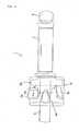
- Fig. 3 is a front view of the throttle device 1 according to one embodiment of the present invention.
- the throttle device 1 is mounted on a right end portion of the handle bar 2 which extends in the vehicle-width direction of the motorcycle and steers the front wheel.
- a substantially cylindrical throttle pipe 6 made of a resin or the like (see Fig. 4 ) is pivotally supported such that the throttle pipe 6 is rotatable within a range of predetermined angle.
- a handle grip 3 which constitutes a grip portion made of rubber or the like is mounted.
- the rider of the vehicle can steer the front wheel by gripping the handle grip 3 and, at the same time, can arbitrarily adjust a rotational angle of the handle grip 3 relative to the handle bar 2 thus adjusting an output of the engine which constitutes a drive source of the vehicle.
- a substantially cylindrical throttle housing 10 which is made of a resin or the like is fixed to a portion of the handle bar 2 on a more vehicle-body center side than the handle grip 3.
- a plurality of handle switches is mounted on the throttle housing 10.
- the plurality of handle switches may include, for example, a seesaw-type kill switch 5a, a pushbutton-type hazard lamp switch 5b, and a starter switch 5c.
- the rider of the vehicle can manipulate the respective switches by extending his/her thumb in a state that the rider grips the handle grip 3 with his/her right hand.
- a throttle sensor unit 20 which detects a rotational angle of the throttle pipe 6 and a throttle returning mechanism 40 which applies a biasing force in the direction so as to return the handle grip 3 to an initial position are housed.
- the handle grip 3 is rotatably held on the handle bar 2 within a range of a predetermined angle and, at the same time, is always biased in the direction toward the initial position, that is, in the direction that the engine output is decreased due to the throttle returning mechanism 40.
- a grip end 4 is fixed to a right end portion of the handle bar 2.
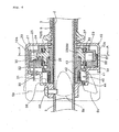
- Fig. 4 is a partially enlarged cross-sectional view of the constitution shown in Fig. 3 .
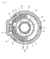
- Fig. 5 is a cross-sectional view taken along a line A-A in Fig. 4 .
- Symbols equal to the symbols used in the above-mentioned constitution indicate identical or similar parts.
- the throttle housing 10 includes an upper housing half body 10a and a lower housing half body 10b which are joined to each other using a plurality of screws (not shown in the drawing) or the like, and the upper housing half body 10a is fixed to the handle bar 2 using a positioning bolt 52.
- a partition wall 36 is formed between a space where the throttle sensor unit 20 and the throttle returning mechanism 40 are housed and a space where the handle switch is mounted. Due to such constitution, it is possible to enhance waterproof and dustproof property of the throttle sensor unit 20 and the throttle returning mechanism 40.
- the throttle housing 10 may be formed in various shapes and may be formed in a shape in which such a partition wall 36 is not arranged in the throttle housing 10.
- a left end side of the throttle pipe 6 in the drawing is inserted into the throttle housing 10 so as to reach the substantially center of the throttle housing 10. Further, on the throttle pipe 6, an annular flange portion 27 which sandwiches a side wall of the throttle housing 10 is formed, and the throttle pipe 6 is held on the handle bar 2 in a non-movable manner in the axial direction by joining the upper housing half body 10a and the lower housing half body 10b to each other. Further, on a portion of an outer peripheral portion of the throttle pipe 6 on a more vehicle-body center side than the flange portion 27, a spline 35 consisting of five axial keys 7 is formed.
- the throttle sensor unit 20 is formed of a resistance potentiometer.
- the throttle sensor unit 20 is formed in an annular shape and is fixed to an inner wall of the throttle housing 10.
- the throttle sensor unit 20 includes a rotary member 23 on which a movable contact 25 of the potentiometer is mounted, a base member 22 on which a fixed contact 30 of the potentiometer is mounted, and a cover member 21 which is engaged with the base member 22.
- the rotary member 23, the base member 22, and the cover member 21 are made of a resin or the like respectively.
- the throttle sensor unit 20 is assembled such that sealing members 33, 34 formed of an oil seal or the like are engaged with both sides of the rotary member 23 in the axial direction and the rotary member 23 is sandwiched between the base member 22 and the cover member 21 from both sides of the rotary member 23.
- the base member 22 and the cover member 21 are fixed to each other by engaging an engaging pawl 50 which is formed on the cover member 21 with an engaging projection 51 which is formed on the base member 22 by fitting. Due to such constitution, the inside of the sensor in which the fixed contact 30 and the movable contact 25 are housed can ensure high waterproof and dustproof property.
- shapes or the like of the engaging pawl 50 and the engaging projection 51 may be variously modified, and the base member 22 and the cover member 21 may be fixed to each other using fastening members such as screws.
- a line 32 which is connected to the fixed contact 30 and outputs a sensor signal is mounted.
- the line 32 penetrates a packing member 31 made of rubber or the like and, thereafter, is guided to the outside of the partition wall 36.
- a spline hole 29 having five key grooves 28 which agree with a spline shape (spline 35) of the throttle pipe 6 is formed.
- the throttle sensor unit 20 is formed as a module and hence, the assembling of the throttle sensor unit 20 and the throttle pipe 6 can be completed by merely engaging the throttle sensor 20 and the throttle pipe 6 by spline fitting whereby the assembling operation can be easily performed. Further, the throttle sensor 20 and the throttle pipe 6 can be simultaneously mounted on the handle bar 2 in a state that the throttle sensor unit 20 and the throttle pipe 6 are assembled to each other and hence, the efficiency of the assembling operation of the throttle device 1 can be enhanced.
- the throttle sensor unit 20 and the throttle pipe 6 are firstly mounted on the handle bar 2 and, thereafter, the throttle housing 10 is mounted on the handle bar 2 so as to cover the throttle unit sensor 20 and the throttle pipe 6 from above and below.
- the movement of the throttle pipe 6 in the axial direction is restricted by the flange portion 27.
- the throttle pipe 6 and the rotary member 23 are engaged with each other by spline fitting and hence, the axial movement of the throttle pipe 6 is not transmitted to the rotary member 23. Accordingly, it is possible to prevent the occurrence of a phenomenon that an axial force is applied to the rotary member 23 and influences the sensor accuracy and the sealing property and the like of the sensor housing.
- the movable contact 25 and the fixed contact 30 which constitute the detection part for detecting a rotational angle of the throttle pipe 6 are formed of a conductive body made of metal or the like respectively.
- the movable contact 25 which is mounted on the projecting portion 24 of the rotary member 23 is brought into contact with the input-side fixed contact 30a and the output-side fixed contact 30b so as to electrically connect both contacts 30a, 30b with each other.
- a contact position of the movable contact 25 with both contacts 30a, 30b is changed along with the rotation of the throttle pipe 6 and hence, an output current value from the line 32 is changed.
- the throttle device is configured to decrease an electric resistance value generated on the fixed contact 30 along with the rotation of the throttle pipe 6 in the counterclockwise direction in the drawing from an initial position of the throttle pipe 6 on a right side of the drawing.
- the throttle returning mechanism 40 which applies a biasing force in the direction of returning the throttle pipe 6 to the initial position is arranged adjacent to the throttle sensor unit 20 in the axial direction.
- a coil spring 44 is wound around a main body portion 42 of the throttle returning mechanism 40, and one end side of the coil spring 44 is engaged with the flange portion 41 and, at the same time, another end portion of the coil spring 44 is engaged with the partition wall 36 of the throttle housing 10.
- the throttle returning mechanism 40 and the throttle sensor unit 20 are arranged to overlap with each other in the axial direction. Due to such constitution, the throttle returning mechanism 40 is arranged on a radially inner side of the throttle sensor unit 20 thus reducing an axial size of the throttle device whereby the miniaturization of the whole throttle device can be realized.
- the rotary member 23 of the throttle sensor unit 20 and the main body portion 42 of the throttle returning mechanism 40 can be simultaneously engaged with the end portion of the throttle pipe 6 by spline fitting in a state that the rotary member 23 and the main body portion 42 overlap each other in the axial direction.
- inventors of the present invention have found that although it is difficult to reduce a thickness of the throttle device in the direction orthogonal to an axis of the throttle sensor unit 20 from a viewpoint of the sensor accuracy, a manufacturing cost and the like, these properties are not influenced even when an axial length of the rotary member 23 which is engaged with the throttle pipe 6 by spline fitting is shortened.
- the projection 43 of the throttle returning mechanism 40 is inserted into the recessed portion of the rotary member 23 which is acquired by such shortening thus reducing a total width consisting of a width of the throttle sensor unit 20 and a width of the throttle returning mechanism 40 in the axial direction. Accordingly, the throttle housing 10 can be miniaturized. Further, due to such constitution, the throttle returning mechanism 40, the throttle sensor unit 20 and the throttle pipe 6 can be simultaneously mounted on the handle bar 2 in a pre-assembled state and hence, the efficiency of the assembling operation of the throttle device 1 can be further enhanced.
- the respective structures or the shapes of the throttle sensor unit 20 and the throttle returning mechanism 40 are not limited to the above-mentioned embodiment, and various modifications are conceivable.
- the rotary member 23 and the main body portion 42 of the throttle returning mechanism 40 may be formed as an integral part of the throttle device 1.
- the throttle device is configured such that the throttle returning mechanism 40 and the throttle sensor unit 20 are arranged on a vehicle-body outer side (in the rightward direction in Fig. 4 ) and, at the same time, the handle switches 5a, 5b and 5c are arranged on a vehicle-body center side (in the leftward direction in Fig. 4 ) with respect to the throttle housing 10. Due to such an arrangement, the respective handle switches can be mounted in the throttle housing 10 by effectively utilizing the space in the inside of the throttle housing 10 thus realizing the miniaturization of the throttle housing 10.
- respective shapes and materials of the handle bar, the throttle pipe and the throttle housing, a shape of a spline shaft-shaped portion formed on the throttle pipe, constitutions of the throttle sensor unit and the throttle returning mechanism and the like are not limited to the above-mentioned constitutions and various modifications are conceivable.
- a non-contact sensor using a Hall element may be adopted in place of the above-mentioned potentiometer.
- a friction means which applies a proper resistance to the rotational operation of the throttle pipe may be provided on the throttle device.
- the friction means is, for example, configured to utilize a slide resistance of a frictional body, and may be housed in the inside of the throttle housing.
- the throttle device according to the present invention is not limited to the motorcycle, and may be applicable to a vehicle such as a three-wheeled vehicle or a four-wheeled vehicle which uses an engine or a motor as a drive source.
- the invention is directed to provide a throttle device which can be assembled to a handle bar after sub-assembling a throttle pipe and a throttle sensor unit to each other.
- a spline 35 is formed on an outer peripheral surface of one end portion of a throttle pipe 6 which is rotatably fitted on a handle bar 2 in the axial direction.
- a throttle sensor unit 20 which is housed in a throttle housing 10 includes a rotary member 23 in which a spline hole 29 is formed, a fixed contact 30 and a movable contact 25 which detect a quantity of rotation of the rotary member 23, and a sensor housing which is fixed to the throttle housing 10.
- the throttle pipe 6 and the throttle sensor unit 20 are mounted on the handle bar 20 after engaging these parts with each other by spline fitting.
- a throttle returning mechanism 40 and the sensor unit 20 are arranged in an overlapping manner in the axial direction by engaging a projection 43 and a recessed portion 26 with each other.
- Handle switches are arranged on the vehicle body center side of the throttle housing 10.
Landscapes
- Engineering & Computer Science (AREA)
- Mechanical Engineering (AREA)
- Control Of Throttle Valves Provided In The Intake System Or In The Exhaust System (AREA)
- Steering Devices For Bicycles And Motorcycles (AREA)
Abstract
Description
- The present invention relates to a throttle device, and more particularly to a throttle device in which a throttle pipe which is rotatably and pivotally supported on a handle bar and a throttle sensor unit which is housed in a throttle housing are engaged with each other by spline fitting so that the throttle device is assembled to the handle bar by sub-assembling the throttle sensor unit in the throttle pipe.
- Conventionally, there has been known a throttle device which allows a rider to detect a throttle operation quantity by detecting a rotational angle of a throttle pipe which is rotatably inserted into a handle bar of a vehicle such as a motorcycle using a sensor.
- Japanese Patent document
JP-A-2003-252273 - Further, Japanese Utility Model Registration No.
2554808 - However, the techniques disclosed in Japanese patent document
JP-A-2003-252273 2554808 - The present invention has been made to overcome the above-mentioned drawbacks of the prior art, and it is an object of the present invention to provide a throttle device which can be assembled to a handle bar in a state that a throttle pipe which is rotatably and pivotally supported on the handle bar and a throttle sensor unit which is housed in a throttle housing are engaged with each other by spline fitting and the throttle sensor unit is sub-assembled to the throttle pipe.
- To achieve the above-mentioned objects, the present invention is firstly characterized in that, in a throttle device which includes a throttle pipe which is rotatably inserted into a handle bar of a vehicle, a throttle housing which is fixed to the handle bar and is rotatably engaged with an outer periphery of the throttle pipe, and a throttle sensor unit which is housed in the throttle housing and detects a rotational angle of the throttle pipe, a spline is formed on an outer peripheral surface of one end portion of the throttle pipe in the axial direction, the throttle sensor unit is formed in an annular shape including a spline hole at a substantially center thereof, and the throttle pipe and the throttle sensor unit are engaged with each other by spline fitting.
- Further, the present invention is secondary characterized in that the throttle device includes a throttle returning mechanism for applying a biasing force in the direction that the throttle pipe is made to return to an initial position thereof, and the throttle returning mechanism is arranged adjacent to the throttle sensor unit and is engaged with the throttle pipe by spline fitting.
- Further, the present invention is thirdly characterized in that the throttle sensor unit and the throttle returning mechanism are arranged in an overlapping manner in the axial direction of the throttle pipe due to the engagement of a projection portion which is formed on the throttle returning mechanism and a recessed portion which is formed on the throttle sensor unit.
- Further, the present invention is fourthly characterized in that the throttle sensor unit includes a rotary member in which the spline hole is formed, a detection part which detects a quantity of rotation of the rotary member, and a sensor housing which houses the rotary member and the detection part and is mounted on the throttle housing in a non-rotatable manner.
- Still further, the present invention is fifthly characterized in that at least one handle switch is mounted on the throttle housing, the throttle sensor and the throttle returning mechanism are arranged on a vehicle-body outer side of the throttle housing, and the handle switch is arranged on a vehicle-body center side of the throttle housing.
- According to a first aspect of the present invention, the spline is formed on the outer peripheral surface of one end portion of the throttle pipe in the axial direction, the throttle sensor unit is formed in an annular shape including the spline hole at a substantially center thereof, and the throttle pipe and the throttle sensor unit are engaged with each other by spline fitting and hence, the assembling operation of the throttle sensor unit and the throttle pipe can be easily performed and, at the same time, the throttle sensor unit and the throttle pipe can be simultaneously mounted on the handle bar in a state that both parts are assembled to each other. Accordingly, the assembling operation of the throttle device can be performed with high efficiency. Further, the throttle pipe and the throttle sensor unit are engaged with each other by spline fitting and hence, even when a force for moving the throttle pipe in the axial direction is applied to the throttle pipe, there is no possibility that the force is transmitted to the throttle sensor unit.
- According to a second aspect of the present invention, the throttle device includes the throttle returning mechanism for applying a biasing force in the direction that the throttle pipe is made to return to an initial position thereof, and the throttle returning mechanism is arranged adjacent to the throttle sensor unit and is engaged with the throttle pipe by spline fitting and hence, the throttle sensor unit and the throttle returning mechanism can be mounted on the handle bar after simultaneously assembling these parts on the spline of the throttle pipe. Accordingly, the assembling operation of the throttle device can be performed with high efficiency.
- According to a third aspect of the present invention, the throttle sensor unit and the throttle returning mechanism are arranged in an overlapping manner in the axial direction of the throttle pipe due to the engagement of a projection portion which is formed on the throttle returning mechanism and a recessed portion which is formed on the throttle sensor unit and hence, a total size consisting of a size of the throttle sensor unit and a size of the throttle returning mechanism in the axial direction can be reduced thus realizing the miniaturization of the throttle housing.
- According to a fourth aspect of the present invention, the throttle sensor unit includes a rotary member in which the spline hole is formed, a detection part which detects a quantity of rotation of the rotary member, and a sensor housing which houses the rotary member and the detection part and is mounted on the throttle housing in a non-rotatable manner and hence, the throttle sensor unit and the throttle pipe can be simultaneously mounted on the handle bar by engaging these parts with each other by spline fitting after performing the assembling of the throttle sensor unit. Further, even when a force for moving the throttle pipe in the axial direction is applied to the throttle pipe, the force is not transmitted to the rotary member and hence, there exists no possibility that the force influences sensor accuracy of the detection part, the sealing property of the sensor housing and the like.
- According to a fifth aspect of the present invention, at least one handle switch is mounted on the throttle housing, the throttle sensor and the throttle returning mechanism are arranged on a vehicle-body outer side of the throttle housing, and the handle switch is arranged on a vehicle-body center side of the throttle housing and hence, the handle switches can be mounted in the throttle housing by effectively utilizing the space in the inside of the throttle housing thus realizing the miniaturization of the throttle housing.
-
-
Fig. 1 is a side view of a motorcycle which includes a throttle device according to one embodiment of the present invention. -
Fig. 2 is a system constitutional view of an engine. -
Fig. 3 is a front view of the throttle device according to one embodiment of the present invention. -
Fig. 4 is a partially enlarged cross-sectional view of the throttle device inFig. 3 . -
Fig. 5 is a cross-sectional view taken along a line A-A inFig. 4 . - Hereinafter, a preferred embodiment of the present invention is explained in detail in conjunction with attached drawings.
Fig. 1 is a side view of a motorcycle 100 which includes a throttle device 1 according to one embodiment of the present invention. On a vehicle-body front portion of avehicle body frame 101, ahead pipe 102 which steerably and pivotally supports a pair of left andright front forks 103 is formed. On thefront forks 103, a front wheel WF is rotatably and pivotally supported, and the front wheel WF can be steered by ahandle bar 2 which is mounted on upper end portions of thefront forks 103. The throttle device 1 is mounted on a right side of thehandle bar 2 which extends in the vehicle width direction. - An
upper cover 104 is arranged on an upper portion of thevehicle body frame 101, and a vehicle-body front side of thehead pipe 102 is covered with a cowling 104. On a lower portion of thevehicle body frame 101, a V-type 4-cylinder engine 107 which arranges acrankshaft 108 in the vehicle width direction is mounted. Inside theupper cover 104, in addition to a fuel tank not shown in the drawing, anair cleaner box 105, afuel injection device 106 which supplies fuel to intake ports of a front cylinder 110F and arear cylinder 110R of theengine 107 and the like are housed. An exhaust gas discharged from the front cylinder 110F is supplied to anexpansion chamber 114 through afront exhaust pipe 112F, and an exhaust gas discharged from therear cylinder 110R is supplied to theexpansion chamber 114 through arear exhaust pipe 112R. The exhaust gas which is supplied to theexpansion chamber 114 is discharged to a rear side of the vehicle body by way of amuffler 115. - On a rear upper portion of the
vehicle body frame 101, aseat frame 121 which supports a seat 119 thereon is mounted, while on a rear lower portion of thevehicle body frame 101, aswing arm 116 which rotatably and pivotally supports a rear wheel WR is swingably and pivotally supported. Theswing arm 116 is suspended downwardly from thevehicle body frame 101 using a rear shock unit 117. A rotational drive force of theengine 107 is transmitted to the rear wheel WR by way of adrive chain 115. On thevehicle body frame 101 arranged below a swing axis of theswing arm 116, aside stand 120 which supports a vehicle body when the vehicle is stopped is mounted. -
Fig. 2 is a system constitutional view of theengine 107. In an intake pipe 157 of theengine 107, anelectronic control throttle 153 which opens and closes athrottle valve 155 using anactuator 154 is interposed, and air is sucked into the inside ofcombustion chambers 166 of the front and rear cylinders by way of theelectronic control throttle 153 and anintake valve 161. - Exhaust gas is discharged from the
combustion chamber 166 by way of anexhaust valve 163 and is purified by acatalyst device 113 and, thereafter, is discharged to atmosphere through themuffler 115. Theintake valve 161 and theexhaust valve 163 are individually opened and closed by cams which are formed on an intake-side cam shaft 162 and an exhaust-side cam shaft 164 respectively. - In an
intake port 159 of each cylinder, an electromagneticfuel injection valve 160 is mounted. When thefuel injection valve 160 is opened in response to an injection pulse signal, thefuel injection valve 160 injects fuel whose pressure is adjusted to a predetermined pressure toward theintake valve 161. - A
control unit 150 which incorporates a micro computer therein systematically controls theelectronic control throttle 153, thefuel injection valve 160, an ignition device not shown in the drawing and the like. Further, to thecontrol unit 150, detection signals are inputted from various sensors such as anair flow meter 158 which detects a quantity of intake air into theengine 107, a throttle sensor unit (APS) 20 which detects a throttle opening of the throttle device 1, acrank angle sensor 167 which detects a rotational angle of thecrankshaft 108, a throttlevalve opening sensor 156 which detects an opening of thethrottle valve 155, and avehicle speed sensor 151 which detects a vehicle speed. Here, to thecontrol unit 114, in addition to the detection signals from the various sensors, a battery voltage signal, a brake operation signal and the like are inputted. Thecontrol unit 150 controls driving of theelectronic control throttle 153 in response to a throttle operation quantity of a rider and the signals from the various sensors. -
Fig. 3 is a front view of the throttle device 1 according to one embodiment of the present invention. The throttle device 1 is mounted on a right end portion of thehandle bar 2 which extends in the vehicle-width direction of the motorcycle and steers the front wheel. On thehandle bar 2 formed of a metal-made pipe or the like, a substantiallycylindrical throttle pipe 6 made of a resin or the like (seeFig. 4 ) is pivotally supported such that thethrottle pipe 6 is rotatable within a range of predetermined angle. On an outer peripheral portion of thethrottle pipe 6, ahandle grip 3 which constitutes a grip portion made of rubber or the like is mounted. The rider of the vehicle can steer the front wheel by gripping thehandle grip 3 and, at the same time, can arbitrarily adjust a rotational angle of thehandle grip 3 relative to thehandle bar 2 thus adjusting an output of the engine which constitutes a drive source of the vehicle. - Further, a substantially
cylindrical throttle housing 10 which is made of a resin or the like is fixed to a portion of thehandle bar 2 on a more vehicle-body center side than thehandle grip 3. A plurality of handle switches is mounted on thethrottle housing 10. The plurality of handle switches may include, for example, a seesaw-type kill switch 5a, a pushbutton-typehazard lamp switch 5b, and astarter switch 5c. The rider of the vehicle can manipulate the respective switches by extending his/her thumb in a state that the rider grips thehandle grip 3 with his/her right hand. - In the inside of the
throttle housing 10, athrottle sensor unit 20 which detects a rotational angle of thethrottle pipe 6 and athrottle returning mechanism 40 which applies a biasing force in the direction so as to return thehandle grip 3 to an initial position are housed. Thehandle grip 3 is rotatably held on thehandle bar 2 within a range of a predetermined angle and, at the same time, is always biased in the direction toward the initial position, that is, in the direction that the engine output is decreased due to thethrottle returning mechanism 40. Here, a grip end 4 is fixed to a right end portion of thehandle bar 2. -
Fig. 4 is a partially enlarged cross-sectional view of the constitution shown inFig. 3 . Further,Fig. 5 is a cross-sectional view taken along a line A-A inFig. 4 . Symbols equal to the symbols used in the above-mentioned constitution indicate identical or similar parts. Thethrottle housing 10 includes an upperhousing half body 10a and a lowerhousing half body 10b which are joined to each other using a plurality of screws (not shown in the drawing) or the like, and the upperhousing half body 10a is fixed to thehandle bar 2 using apositioning bolt 52. - Here, in the
throttle housing 10 according to this embodiment, apartition wall 36 is formed between a space where thethrottle sensor unit 20 and thethrottle returning mechanism 40 are housed and a space where the handle switch is mounted. Due to such constitution, it is possible to enhance waterproof and dustproof property of thethrottle sensor unit 20 and thethrottle returning mechanism 40. However, thethrottle housing 10 may be formed in various shapes and may be formed in a shape in which such apartition wall 36 is not arranged in thethrottle housing 10. - A left end side of the
throttle pipe 6 in the drawing is inserted into thethrottle housing 10 so as to reach the substantially center of thethrottle housing 10. Further, on thethrottle pipe 6, anannular flange portion 27 which sandwiches a side wall of thethrottle housing 10 is formed, and thethrottle pipe 6 is held on thehandle bar 2 in a non-movable manner in the axial direction by joining the upperhousing half body 10a and the lowerhousing half body 10b to each other. Further, on a portion of an outer peripheral portion of thethrottle pipe 6 on a more vehicle-body center side than theflange portion 27, aspline 35 consisting of fiveaxial keys 7 is formed. - The
throttle sensor unit 20 is formed of a resistance potentiometer. Thethrottle sensor unit 20 is formed in an annular shape and is fixed to an inner wall of thethrottle housing 10. Thethrottle sensor unit 20 includes arotary member 23 on which amovable contact 25 of the potentiometer is mounted, abase member 22 on which a fixedcontact 30 of the potentiometer is mounted, and acover member 21 which is engaged with thebase member 22. Therotary member 23, thebase member 22, and thecover member 21 are made of a resin or the like respectively. - The
throttle sensor unit 20 is assembled such that sealingmembers rotary member 23 in the axial direction and therotary member 23 is sandwiched between thebase member 22 and thecover member 21 from both sides of therotary member 23. Thebase member 22 and thecover member 21 are fixed to each other by engaging an engagingpawl 50 which is formed on thecover member 21 with an engagingprojection 51 which is formed on thebase member 22 by fitting. Due to such constitution, the inside of the sensor in which the fixedcontact 30 and themovable contact 25 are housed can ensure high waterproof and dustproof property. Here, shapes or the like of the engagingpawl 50 and the engagingprojection 51 may be variously modified, and thebase member 22 and thecover member 21 may be fixed to each other using fastening members such as screws. On a back side of thebase member 22, aline 32 which is connected to the fixedcontact 30 and outputs a sensor signal is mounted. Theline 32 penetrates a packingmember 31 made of rubber or the like and, thereafter, is guided to the outside of thepartition wall 36. - Further, in the
rotary member 23, aspline hole 29 having fivekey grooves 28 which agree with a spline shape (spline 35) of thethrottle pipe 6 is formed. By engaging thethrottle pipe 6 with thespline hole 29, the assembling of both of thethrottle sensor unit 20 and thethrottle pipe 6 is completed. - As described above, the
throttle sensor unit 20 is formed as a module and hence, the assembling of thethrottle sensor unit 20 and thethrottle pipe 6 can be completed by merely engaging thethrottle sensor 20 and thethrottle pipe 6 by spline fitting whereby the assembling operation can be easily performed. Further, thethrottle sensor 20 and thethrottle pipe 6 can be simultaneously mounted on thehandle bar 2 in a state that thethrottle sensor unit 20 and thethrottle pipe 6 are assembled to each other and hence, the efficiency of the assembling operation of the throttle device 1 can be enhanced. In this embodiment, thethrottle sensor unit 20 and thethrottle pipe 6 are firstly mounted on thehandle bar 2 and, thereafter, thethrottle housing 10 is mounted on thehandle bar 2 so as to cover thethrottle unit sensor 20 and thethrottle pipe 6 from above and below. - In this embodiment, the movement of the
throttle pipe 6 in the axial direction is restricted by theflange portion 27. However, for example, even when a slight gap is formed between theflange portion 27 and the wall portion of thethrottle housing 10 so that thethrottle pipe 6 may be allowed to move in the axial direction within a range of the gap, thethrottle pipe 6 and therotary member 23 are engaged with each other by spline fitting and hence, the axial movement of thethrottle pipe 6 is not transmitted to therotary member 23. Accordingly, it is possible to prevent the occurrence of a phenomenon that an axial force is applied to therotary member 23 and influences the sensor accuracy and the sealing property and the like of the sensor housing. - The
movable contact 25 and the fixedcontact 30 which constitute the detection part for detecting a rotational angle of thethrottle pipe 6 are formed of a conductive body made of metal or the like respectively. Themovable contact 25 which is mounted on the projectingportion 24 of therotary member 23 is brought into contact with the input-sidefixed contact 30a and the output-sidefixed contact 30b so as to electrically connect bothcontacts movable contact 25 with bothcontacts throttle pipe 6 and hence, an output current value from theline 32 is changed. In this embodiment, the throttle device is configured to decrease an electric resistance value generated on the fixedcontact 30 along with the rotation of thethrottle pipe 6 in the counterclockwise direction in the drawing from an initial position of thethrottle pipe 6 on a right side of the drawing. - Further, the
throttle returning mechanism 40 which applies a biasing force in the direction of returning thethrottle pipe 6 to the initial position is arranged adjacent to thethrottle sensor unit 20 in the axial direction. Acoil spring 44 is wound around amain body portion 42 of thethrottle returning mechanism 40, and one end side of thecoil spring 44 is engaged with theflange portion 41 and, at the same time, another end portion of thecoil spring 44 is engaged with thepartition wall 36 of thethrottle housing 10. On a right side of themain body portion 42 in the drawing (seeFig. 4 ), acylindrical projection 43 which is engaged with thethrottle pipe 6 by spline fitting is formed. By inserting theprojection 43 into the recessedportion 26 formed on therotary member 23, thethrottle returning mechanism 40 and thethrottle sensor unit 20 are arranged to overlap with each other in the axial direction. Due to such constitution, thethrottle returning mechanism 40 is arranged on a radially inner side of thethrottle sensor unit 20 thus reducing an axial size of the throttle device whereby the miniaturization of the whole throttle device can be realized. - According to the above-mentioned constitution, the
rotary member 23 of thethrottle sensor unit 20 and themain body portion 42 of thethrottle returning mechanism 40 can be simultaneously engaged with the end portion of thethrottle pipe 6 by spline fitting in a state that therotary member 23 and themain body portion 42 overlap each other in the axial direction. In this embodiment, inventors of the present invention have found that although it is difficult to reduce a thickness of the throttle device in the direction orthogonal to an axis of thethrottle sensor unit 20 from a viewpoint of the sensor accuracy, a manufacturing cost and the like, these properties are not influenced even when an axial length of therotary member 23 which is engaged with thethrottle pipe 6 by spline fitting is shortened. Based on such finding, in this embodiment, theprojection 43 of thethrottle returning mechanism 40 is inserted into the recessed portion of therotary member 23 which is acquired by such shortening thus reducing a total width consisting of a width of thethrottle sensor unit 20 and a width of thethrottle returning mechanism 40 in the axial direction. Accordingly, thethrottle housing 10 can be miniaturized. Further, due to such constitution, thethrottle returning mechanism 40, thethrottle sensor unit 20 and thethrottle pipe 6 can be simultaneously mounted on thehandle bar 2 in a pre-assembled state and hence, the efficiency of the assembling operation of the throttle device 1 can be further enhanced. - Here, the respective structures or the shapes of the
throttle sensor unit 20 and thethrottle returning mechanism 40 are not limited to the above-mentioned embodiment, and various modifications are conceivable. For example, therotary member 23 and themain body portion 42 of thethrottle returning mechanism 40 may be formed as an integral part of the throttle device 1. - Further, in this embodiment, the throttle device is configured such that the
throttle returning mechanism 40 and thethrottle sensor unit 20 are arranged on a vehicle-body outer side (in the rightward direction inFig. 4 ) and, at the same time, thehandle switches Fig. 4 ) with respect to thethrottle housing 10. Due to such an arrangement, the respective handle switches can be mounted in thethrottle housing 10 by effectively utilizing the space in the inside of thethrottle housing 10 thus realizing the miniaturization of thethrottle housing 10. - Here, respective shapes and materials of the handle bar, the throttle pipe and the throttle housing, a shape of a spline shaft-shaped portion formed on the throttle pipe, constitutions of the throttle sensor unit and the throttle returning mechanism and the like are not limited to the above-mentioned constitutions and various modifications are conceivable. For example, as the sensor portion of the throttle sensor unit, a non-contact sensor using a Hall element may be adopted in place of the above-mentioned potentiometer. Further, on the throttle device, a friction means which applies a proper resistance to the rotational operation of the throttle pipe may be provided. The friction means is, for example, configured to utilize a slide resistance of a frictional body, and may be housed in the inside of the throttle housing.
- The throttle device according to the present invention is not limited to the motorcycle, and may be applicable to a vehicle such as a three-wheeled vehicle or a four-wheeled vehicle which uses an engine or a motor as a drive source.
- The invention is directed to provide a throttle device which can be assembled to a handle bar after sub-assembling a throttle pipe and a throttle sensor unit to each other.
- A
spline 35 is formed on an outer peripheral surface of one end portion of athrottle pipe 6 which is rotatably fitted on ahandle bar 2 in the axial direction. Athrottle sensor unit 20 which is housed in athrottle housing 10 includes arotary member 23 in which aspline hole 29 is formed, a fixedcontact 30 and amovable contact 25 which detect a quantity of rotation of therotary member 23, and a sensor housing which is fixed to thethrottle housing 10. Thethrottle pipe 6 and thethrottle sensor unit 20 are mounted on thehandle bar 20 after engaging these parts with each other by spline fitting. Athrottle returning mechanism 40 and thesensor unit 20 are arranged in an overlapping manner in the axial direction by engaging aprojection 43 and a recessedportion 26 with each other. Handle switches are arranged on the vehicle body center side of thethrottle housing 10.
Claims (5)
- A throttle device (1) comprising:a throttle pipe (6) which is rotatably inserted into a handle bar (2) of a vehicle;a throttle housing (10) which is fixed to the handle bar (2) and is rotatably engaged with an outer periphery of the throttle pipe (6); anda throttle sensor unit (20) which is housed in the throttle housing (10) and detects a rotational angle of the throttle pipe (6), whereina spline (35) is formed on an outer peripheral surface of one end portion of the throttle pipe (6) in the axial direction,the throttle sensor unit (20) is formed in an annular shape including a spline hole (29) at a substantially center thereof, andthe throttle pipe (6) and the throttle sensor unit (20) are engaged with each other by spline fitting.
- A throttle device (1) according to claim 1, wherein the throttle device (1) includes a throttle returning mechanism (40) for applying a biasing force in the direction that the throttle pipe (6) is made to return to an initial position thereof, and
the throttle returning mechanism (40) is arranged adjacent to the throttle sensor unit (20) and is engaged with the throttle pipe (6) by spline fitting. - A throttle device (1) according to claim 1 or claim 2, wherein the throttle sensor unit (20) and the throttle returning mechanism (40) are arranged in an overlapping manner in the axial direction of the throttle pipe (6) due to the engagement of a projection portion which is formed on the throttle returning mechanism (40) and a recessed portion (26) which is formed on the throttle sensor unit (20).
- A throttle device (1) according to any one of claims 1 to 3, wherein the throttle sensor unit (20) includes a rotary member (23) in which the spline hole (29) is formed, a detection part (25, 30) which detects a quantity of rotation of the rotary member (23), and a sensor housing which houses the rotary member (23) and the detection part (25, 30) and is mounted on the throttle housing (10) in a non-rotatable manner.
- A throttle device (1) according to any one of claims 1 to 4, wherein at least one handle switch (5a, 5b, 5c) is mounted on the throttle housing (10),
the throttle sensor and the throttle returning mechanism (40) are arranged on a vehicle-body outer side of the throttle housing (10), and
the handle switch is arranged on a vehicle-body center side of the throttle housing (10).
Applications Claiming Priority (1)
| Application Number | Priority Date | Filing Date | Title |
|---|---|---|---|
| JP2008137983A JP5023397B2 (en) | 2008-05-27 | 2008-05-27 | Throttle device |
Publications (2)
| Publication Number | Publication Date |
|---|---|
| EP2128010A1 true EP2128010A1 (en) | 2009-12-02 |
| EP2128010B1 EP2128010B1 (en) | 2010-09-22 |
Family
ID=40651274
Family Applications (1)
| Application Number | Title | Priority Date | Filing Date |
|---|---|---|---|
| EP09155225A Ceased EP2128010B1 (en) | 2008-05-27 | 2009-03-16 | Vehicle having a throttle device |
Country Status (4)
| Country | Link |
|---|---|
| US (1) | US8051939B2 (en) |
| EP (1) | EP2128010B1 (en) |
| JP (1) | JP5023397B2 (en) |
| DE (1) | DE602009000222D1 (en) |
Cited By (4)
| Publication number | Priority date | Publication date | Assignee | Title |
|---|---|---|---|---|
| EP2644491A1 (en) * | 2012-03-27 | 2013-10-02 | Honda Motor Co., Ltd. | Throttle device |
| CN104709424A (en) * | 2013-12-16 | 2015-06-17 | 东洋电装株式会社 | Method of assembling throttle device |
| CN114718740A (en) * | 2022-04-14 | 2022-07-08 | 江阴长江电器有限公司 | Engine starting, stopping and accelerator adjusting device for engineering machinery and manufacturing method thereof |
| CN117485458A (en) * | 2022-08-02 | 2024-02-02 | 川崎摩托株式会社 | Transportation |
Families Citing this family (17)
| Publication number | Priority date | Publication date | Assignee | Title |
|---|---|---|---|---|
| JP2861370B2 (en) | 1990-11-09 | 1999-02-24 | 三菱マテリアル株式会社 | Wastewater treatment method |
| JP2861371B2 (en) | 1990-11-09 | 1999-02-24 | 三菱マテリアル株式会社 | Wastewater treatment method |
| JP5268572B2 (en) * | 2008-11-06 | 2013-08-21 | 株式会社ミクニ | Accelerator operating device |
| JP5339604B2 (en) * | 2009-03-30 | 2013-11-13 | 本田技研工業株式会社 | Motorcycle |
| WO2010135472A2 (en) * | 2009-05-19 | 2010-11-25 | Ev-Ip, Llc | Methods and apparatus for utilizing electrically powered vehicles |
| WO2011065330A1 (en) * | 2009-11-24 | 2011-06-03 | ヤマハ発動機株式会社 | Saddled vehicle |
| JP5358417B2 (en) * | 2009-12-08 | 2013-12-04 | 本田技研工業株式会社 | Accelerator operating device |
| JP5777613B2 (en) * | 2010-06-02 | 2015-09-09 | 株式会社ミクニ | Accelerator device |
| JP5745301B2 (en) * | 2011-03-25 | 2015-07-08 | 本田技研工業株式会社 | Throttle sensor mounting structure |
| JP2015182634A (en) * | 2014-03-25 | 2015-10-22 | 本田技研工業株式会社 | Operation device of saddle type vehicle |
| CN109625143B (en) * | 2019-01-18 | 2024-10-18 | 山东五星车辆股份有限公司 | Electric switch rotating handle and electric vehicle |
| IT202000026828A1 (en) * | 2020-11-10 | 2022-05-10 | Bitron Spa | KNOB CONTROL DEVICE, PARTICULARLY FOR MOTOR VEHICLES |
| USD1120012S1 (en) | 2023-07-31 | 2026-03-24 | Northern Tool & Equipment Company, Inc. | Engine assembly |
| USD1090635S1 (en) | 2023-07-31 | 2025-08-26 | Northern Tool & Equipment Company, Inc. | Engine assembly |
| USD1103214S1 (en) | 2023-07-31 | 2025-11-25 | Northern Tool & Equipment Company, Inc. | Engine assembly |
| USD1099161S1 (en) | 2023-07-31 | 2025-10-21 | Northern Tool & Equipment Company, Inc. | Engine assembly |
| USD1103215S1 (en) | 2023-07-31 | 2025-11-25 | Northern Tool & Equipment Company, Inc. | Engine assembly |
Citations (6)
| Publication number | Priority date | Publication date | Assignee | Title |
|---|---|---|---|---|
| JP2554808B2 (en) | 1991-12-09 | 1996-11-20 | 積水化学工業株式会社 | Basement unit connection structure |
| EP0759393A1 (en) * | 1995-03-13 | 1997-02-26 | Sakae Co., Ltd. | Bicycle and speed change operating device for the same |
| DE10027193A1 (en) | 2000-05-31 | 2001-12-06 | Magenwirth Gmbh Co Gustav | Rotary accelerator grip, e.g. for motor cycle, has electrical element that provides electrical signal correlated with rotary position of grip tube on handlebar for operating actuator |
| JP2003252273A (en) | 2002-02-26 | 2003-09-10 | Yamaha Motor Co Ltd | Throttle opening detector |
| EP1464571A2 (en) | 2003-04-04 | 2004-10-06 | AB Elektronik GmbH | Electronic throttle system for motorcycles |
| US20070157902A1 (en) * | 2006-01-10 | 2007-07-12 | Harley-Davidson Motor Company Group, Inc. | Throttle position sensor |
Family Cites Families (6)
| Publication number | Priority date | Publication date | Assignee | Title |
|---|---|---|---|---|
| JP4326617B2 (en) * | 1999-01-29 | 2009-09-09 | ヤマハ発動機株式会社 | Small planing boat |
| JP2003303532A (en) * | 2002-04-09 | 2003-10-24 | Alps Electric Co Ltd | Combined operation type electric component |
| JP2003328784A (en) * | 2002-05-16 | 2003-11-19 | Kawasaki Heavy Ind Ltd | Vehicle throttle device |
| US6978694B2 (en) * | 2002-12-06 | 2005-12-27 | Magneti Marelli Powertrain U.S.A., Inc. | Handlebar throttle controller with hysteresis |
| US20070182514A1 (en) * | 2003-10-23 | 2007-08-09 | Delphi Technologies, Inc. | Control cartridge and control handle including same |
| US7735470B2 (en) * | 2007-01-10 | 2010-06-15 | Delphi Technologies, Inc. | Throttle control cartridge with double cam to force idle position |
-
2008
- 2008-05-27 JP JP2008137983A patent/JP5023397B2/en not_active Expired - Fee Related
-
2009
- 2009-03-16 EP EP09155225A patent/EP2128010B1/en not_active Ceased
- 2009-03-16 DE DE602009000222T patent/DE602009000222D1/en active Active
- 2009-05-07 US US12/387,810 patent/US8051939B2/en not_active Expired - Fee Related
Patent Citations (6)
| Publication number | Priority date | Publication date | Assignee | Title |
|---|---|---|---|---|
| JP2554808B2 (en) | 1991-12-09 | 1996-11-20 | 積水化学工業株式会社 | Basement unit connection structure |
| EP0759393A1 (en) * | 1995-03-13 | 1997-02-26 | Sakae Co., Ltd. | Bicycle and speed change operating device for the same |
| DE10027193A1 (en) | 2000-05-31 | 2001-12-06 | Magenwirth Gmbh Co Gustav | Rotary accelerator grip, e.g. for motor cycle, has electrical element that provides electrical signal correlated with rotary position of grip tube on handlebar for operating actuator |
| JP2003252273A (en) | 2002-02-26 | 2003-09-10 | Yamaha Motor Co Ltd | Throttle opening detector |
| EP1464571A2 (en) | 2003-04-04 | 2004-10-06 | AB Elektronik GmbH | Electronic throttle system for motorcycles |
| US20070157902A1 (en) * | 2006-01-10 | 2007-07-12 | Harley-Davidson Motor Company Group, Inc. | Throttle position sensor |
Cited By (8)
| Publication number | Priority date | Publication date | Assignee | Title |
|---|---|---|---|---|
| EP2644491A1 (en) * | 2012-03-27 | 2013-10-02 | Honda Motor Co., Ltd. | Throttle device |
| CN103359245A (en) * | 2012-03-27 | 2013-10-23 | 本田技研工业株式会社 | Throttle device |
| CN104709424A (en) * | 2013-12-16 | 2015-06-17 | 东洋电装株式会社 | Method of assembling throttle device |
| CN114718740A (en) * | 2022-04-14 | 2022-07-08 | 江阴长江电器有限公司 | Engine starting, stopping and accelerator adjusting device for engineering machinery and manufacturing method thereof |
| CN114718740B (en) * | 2022-04-14 | 2024-04-23 | 江阴长江电器股份有限公司 | Engine start-stop and throttle adjusting device for engineering machinery and manufacturing method thereof |
| CN117485458A (en) * | 2022-08-02 | 2024-02-02 | 川崎摩托株式会社 | Transportation |
| EP4316965A1 (en) * | 2022-08-02 | 2024-02-07 | Kawasaki Motors, Ltd. | Vehicle |
| US12337925B2 (en) | 2022-08-02 | 2025-06-24 | Kawasaki Motors, Ltd. | Vehicle |
Also Published As
| Publication number | Publication date |
|---|---|
| DE602009000222D1 (en) | 2010-11-04 |
| US8051939B2 (en) | 2011-11-08 |
| US20090293668A1 (en) | 2009-12-03 |
| JP5023397B2 (en) | 2012-09-12 |
| EP2128010B1 (en) | 2010-09-22 |
| JP2009287411A (en) | 2009-12-10 |
Similar Documents
| Publication | Publication Date | Title |
|---|---|---|
| EP2128010B1 (en) | Vehicle having a throttle device | |
| EP2011728B1 (en) | Vehicle having a throttle device | |
| EP1905987B1 (en) | Air intake control system for internal combustion engine of a vehicle | |
| US9086719B2 (en) | Throttle control apparatus for a saddle-type vehicle, and vehicle including same | |
| US8186333B2 (en) | Vehicle having internal combustion engine with supercharger | |
| US7311082B2 (en) | Straddle type vehicle having an electronic throttle valve system | |
| EP1719891B1 (en) | Electronic throttle device | |
| JP2009013834A (en) | Vehicle throttle device | |
| US20180045300A1 (en) | Vehicle shift control device | |
| EP2639147B1 (en) | Saddle riding type vehicle | |
| JP5966650B2 (en) | Vehicle transmission | |
| JP4990175B2 (en) | Variable valve operating device for motorcycle engine and motorcycle | |
| EP3379064B1 (en) | Cylinder head of internal combustion engine | |
| JP2011025763A (en) | Motorcycle | |
| JP2007297053A (en) | Vehicle throttle device | |
| CN100550578C (en) | Drive unit | |
| US10309267B2 (en) | Variable valve mechanism, engine, and automatic two-wheeled vehicle | |
| JP5385658B2 (en) | V type internal combustion engine with variable valve mechanism for motorcycle | |
| WO2024134835A1 (en) | Straddled vehicle | |
| JP2014118914A (en) | Electronic control throttle device | |
| WO2018021399A1 (en) | Engine system and straddle-type vehicle | |
| JP2005076620A (en) | Engine cam angle sensor mounting structure and motorcycle equipped with the engine employing the structure | |
| JP2013234576A (en) | Cam angle sensor mounting structure of internal combustion engine | |
| JP2013155648A (en) | Valve gear of internal combustion engine | |
| JP2013208998A (en) | Accelerator opening detection device |
Legal Events
| Date | Code | Title | Description |
|---|---|---|---|
| PUAI | Public reference made under article 153(3) epc to a published international application that has entered the european phase |
Free format text: ORIGINAL CODE: 0009012 |
|
| 17P | Request for examination filed |
Effective date: 20090316 |
|
| AK | Designated contracting states |
Kind code of ref document: A1 Designated state(s): AT BE BG CH CY CZ DE DK EE ES FI FR GB GR HR HU IE IS IT LI LT LU LV MC MK MT NL NO PL PT RO SE SI SK TR |
|
| AX | Request for extension of the european patent |
Extension state: AL BA RS |
|
| GRAP | Despatch of communication of intention to grant a patent |
Free format text: ORIGINAL CODE: EPIDOSNIGR1 |
|
| RTI1 | Title (correction) |
Free format text: VEHICLE HAVING A THROTTLE DEVICE |
|
| GRAS | Grant fee paid |
Free format text: ORIGINAL CODE: EPIDOSNIGR3 |
|
| AKX | Designation fees paid |
Designated state(s): DE FR IT |
|
| GRAA | (expected) grant |
Free format text: ORIGINAL CODE: 0009210 |
|
| AK | Designated contracting states |
Kind code of ref document: B1 Designated state(s): DE FR IT |
|
| REF | Corresponds to: |
Ref document number: 602009000222 Country of ref document: DE Date of ref document: 20101104 Kind code of ref document: P |
|
| PLBE | No opposition filed within time limit |
Free format text: ORIGINAL CODE: 0009261 |
|
| STAA | Information on the status of an ep patent application or granted ep patent |
Free format text: STATUS: NO OPPOSITION FILED WITHIN TIME LIMIT |
|
| 26N | No opposition filed |
Effective date: 20110623 |
|
| REG | Reference to a national code |
Ref country code: DE Ref legal event code: R097 Ref document number: 602009000222 Country of ref document: DE Effective date: 20110623 |
|
| REG | Reference to a national code |
Ref country code: DE Ref legal event code: R084 Ref document number: 602009000222 Country of ref document: DE |
|
| REG | Reference to a national code |
Ref country code: DE Ref legal event code: R084 Ref document number: 602009000222 Country of ref document: DE Effective date: 20141120 |
|
| REG | Reference to a national code |
Ref country code: FR Ref legal event code: PLFP Year of fee payment: 8 |
|
| REG | Reference to a national code |
Ref country code: FR Ref legal event code: PLFP Year of fee payment: 9 |
|
| REG | Reference to a national code |
Ref country code: FR Ref legal event code: PLFP Year of fee payment: 10 |
|
| PGFP | Annual fee paid to national office [announced via postgrant information from national office to epo] |
Ref country code: LU Payment date: 20190221 Year of fee payment: 15 |
|
| PGFP | Annual fee paid to national office [announced via postgrant information from national office to epo] |
Ref country code: FR Payment date: 20190213 Year of fee payment: 11 |
|
| PG25 | Lapsed in a contracting state [announced via postgrant information from national office to epo] |
Ref country code: FR Free format text: LAPSE BECAUSE OF NON-PAYMENT OF DUE FEES Effective date: 20200331 |
|
| PGFP | Annual fee paid to national office [announced via postgrant information from national office to epo] |
Ref country code: DE Payment date: 20210302 Year of fee payment: 13 |
|
| PG25 | Lapsed in a contracting state [announced via postgrant information from national office to epo] |
Ref country code: IT Free format text: LAPSE BECAUSE OF NON-PAYMENT OF DUE FEES Effective date: 20200316 |
|
| REG | Reference to a national code |
Ref country code: DE Ref legal event code: R119 Ref document number: 602009000222 Country of ref document: DE |
|
| PG25 | Lapsed in a contracting state [announced via postgrant information from national office to epo] |
Ref country code: DE Free format text: LAPSE BECAUSE OF NON-PAYMENT OF DUE FEES Effective date: 20221001 |