EP2127855A1 - Tool and method for producing aircraft ring frames from a composite material - Google Patents
Tool and method for producing aircraft ring frames from a composite material Download PDFInfo
- Publication number
- EP2127855A1 EP2127855A1 EP07730485A EP07730485A EP2127855A1 EP 2127855 A1 EP2127855 A1 EP 2127855A1 EP 07730485 A EP07730485 A EP 07730485A EP 07730485 A EP07730485 A EP 07730485A EP 2127855 A1 EP2127855 A1 EP 2127855A1
- Authority
- EP
- European Patent Office
- Prior art keywords
- jig
- preforms
- curing
- injecting
- frame
- Prior art date
- Legal status (The legal status is an assumption and is not a legal conclusion. Google has not performed a legal analysis and makes no representation as to the accuracy of the status listed.)
- Withdrawn
Links
Images


Classifications
-
- B—PERFORMING OPERATIONS; TRANSPORTING
- B29—WORKING OF PLASTICS; WORKING OF SUBSTANCES IN A PLASTIC STATE IN GENERAL
- B29C—SHAPING OR JOINING OF PLASTICS; SHAPING OF MATERIAL IN A PLASTIC STATE, NOT OTHERWISE PROVIDED FOR; AFTER-TREATMENT OF THE SHAPED PRODUCTS, e.g. REPAIRING
- B29C70/00—Shaping composites, i.e. plastics material comprising reinforcements, fillers or preformed parts, e.g. inserts
- B29C70/04—Shaping composites, i.e. plastics material comprising reinforcements, fillers or preformed parts, e.g. inserts comprising reinforcements only, e.g. self-reinforcing plastics
- B29C70/28—Shaping operations therefor
- B29C70/40—Shaping or impregnating by compression not applied
- B29C70/42—Shaping or impregnating by compression not applied for producing articles of definite length, i.e. discrete articles
- B29C70/46—Shaping or impregnating by compression not applied for producing articles of definite length, i.e. discrete articles using matched moulds, e.g. for deforming sheet moulding compounds [SMC] or prepregs
- B29C70/48—Shaping or impregnating by compression not applied for producing articles of definite length, i.e. discrete articles using matched moulds, e.g. for deforming sheet moulding compounds [SMC] or prepregs and impregnating the reinforcements in the closed mould, e.g. resin transfer moulding [RTM], e.g. by vacuum
-
- B—PERFORMING OPERATIONS; TRANSPORTING
- B29—WORKING OF PLASTICS; WORKING OF SUBSTANCES IN A PLASTIC STATE IN GENERAL
- B29C—SHAPING OR JOINING OF PLASTICS; SHAPING OF MATERIAL IN A PLASTIC STATE, NOT OTHERWISE PROVIDED FOR; AFTER-TREATMENT OF THE SHAPED PRODUCTS, e.g. REPAIRING
- B29C70/00—Shaping composites, i.e. plastics material comprising reinforcements, fillers or preformed parts, e.g. inserts
- B29C70/04—Shaping composites, i.e. plastics material comprising reinforcements, fillers or preformed parts, e.g. inserts comprising reinforcements only, e.g. self-reinforcing plastics
- B29C70/06—Fibrous reinforcements only
- B29C70/08—Fibrous reinforcements only comprising combinations of different forms of fibrous reinforcements incorporated in matrix material, forming one or more layers, and with or without non-reinforced layers
- B29C70/083—Combinations of continuous fibres or fibrous profiled structures oriented in one direction and reinforcements forming a two dimensional structure, e.g. mats
- B29C70/085—Combinations of continuous fibres or fibrous profiled structures oriented in one direction and reinforcements forming a two dimensional structure, e.g. mats the structure being deformed in a three dimensional configuration
-
- B—PERFORMING OPERATIONS; TRANSPORTING
- B29—WORKING OF PLASTICS; WORKING OF SUBSTANCES IN A PLASTIC STATE IN GENERAL
- B29D—PRODUCING PARTICULAR ARTICLES FROM PLASTICS OR FROM SUBSTANCES IN A PLASTIC STATE
- B29D99/00—Subject matter not provided for in other groups of this subclass
- B29D99/0003—Producing profiled members, e.g. beams
-
- B—PERFORMING OPERATIONS; TRANSPORTING
- B29—WORKING OF PLASTICS; WORKING OF SUBSTANCES IN A PLASTIC STATE IN GENERAL
- B29L—INDEXING SCHEME ASSOCIATED WITH SUBCLASS B29C, RELATING TO PARTICULAR ARTICLES
- B29L2031/00—Other particular articles
- B29L2031/001—Profiled members, e.g. beams, sections
- B29L2031/008—Profiled members, e.g. beams, sections having a longitudinal cross-section
-
- B—PERFORMING OPERATIONS; TRANSPORTING
- B29—WORKING OF PLASTICS; WORKING OF SUBSTANCES IN A PLASTIC STATE IN GENERAL
- B29L—INDEXING SCHEME ASSOCIATED WITH SUBCLASS B29C, RELATING TO PARTICULAR ARTICLES
- B29L2031/00—Other particular articles
- B29L2031/30—Vehicles, e.g. ships or aircraft, or body parts thereof
- B29L2031/3076—Aircrafts
- B29L2031/3082—Fuselages
-
- Y—GENERAL TAGGING OF NEW TECHNOLOGICAL DEVELOPMENTS; GENERAL TAGGING OF CROSS-SECTIONAL TECHNOLOGIES SPANNING OVER SEVERAL SECTIONS OF THE IPC; TECHNICAL SUBJECTS COVERED BY FORMER USPC CROSS-REFERENCE ART COLLECTIONS [XRACs] AND DIGESTS
- Y02—TECHNOLOGIES OR APPLICATIONS FOR MITIGATION OR ADAPTATION AGAINST CLIMATE CHANGE
- Y02T—CLIMATE CHANGE MITIGATION TECHNOLOGIES RELATED TO TRANSPORTATION
- Y02T50/00—Aeronautics or air transport
- Y02T50/40—Weight reduction
Definitions
- the present invention relates to a jig for the manufacture of composite material frames for aircraft, as well as to a method of manufacturing said frames in a composite material.
- load frames are structural elements in charge of withstanding and transferring the loads from other structural elements of the aircraft, such as the wings or stabilizers.
- the manufacture of the frames is carried out by using machined metal structures or shaped sheet metal structures having in which the part that withstands most of the load is reinforced with machined parts.
- the section that is normally used is obtained in two pieces: on one hand the Z is manufactured, and on the other hand, the brackets which are riveted to the former section are manufactured.
- This process has the drawback that long assembly times are necessary and that the final weight is much greater than what would be desired.
- the present invention relates to a jig for the manufacture of aircraft load frames such that the section of the structure of the obtained frames is done in an integrated manner such that the resulting weight is optimized.
- the manufacturing method proposed by the present invention is carried out by means of a repetitive process with a short times in curing cycles, such that the necessary assembly times are decreased.
- the present invention develops a jig for the manufacture, by means of injection and curing processes, of composite material frame preforms for aircraft fuselages by using RTM (resin transfer molding) technology. Therefore, two preforms are manufactured, one with a C-shaped section and another one with an L-shaped section, together with the preforms of the stabilization ribs of the web of the frames and the preform of the roving or staple fiber to cover the gap between the C shaped preform and the L shaped preform. These preforms are previously manufactured by any known preform manufacturing process.
- the present invention develops a method of manufacturing an aircraft load frame in a composite material.
- aircraft load frames made of a composite material are obtained by means of the jig and the method of manufacture of the present invention with the following advantages:
- the present invention relates to a jig for injecting and curing the preforms of an aeronautic fuselage frame 2 made of a composite material.
- the section to be manufactured is formed by a C-shaped preform ( Figure 4 ) and by an L-shaped angular preform 4 ( Figure 5 ), in addition to different stabilization ribs 5 of the web ( Figure 6 ) and a preform 6 of the roving or staple fiber ( Figure 7 ).
- This arrangement of preforms allows the manufacture of aircraft load frames 2 with the parts for joining them to the following frame integrated therewith, as can be seen in Figure 8 .
- the preforms are made of fabric and reinforcements with unidirectional tape in the inner flanges to increase their moment of inertia and, consequently, their rigidity.
- the jig object of the invention comprises the following elements: an injection and curing jig 7, a vacuum system 8 and a closing and heating system.
- the injection and curing jig comprises different members:
- the vacuum system 8 comprises the following elements:
- the present invention develops a method of manufacturing composite material load frames for aircraft comprising the following steps:
Abstract
Description
- The present invention relates to a jig for the manufacture of composite material frames for aircraft, as well as to a method of manufacturing said frames in a composite material.
- In addition to conferring shape and rigidity to the aircraft fuselage, load frames are structural elements in charge of withstanding and transferring the loads from other structural elements of the aircraft, such as the wings or stabilizers.
- In the state of the art, the manufacture of the frames is carried out by using machined metal structures or shaped sheet metal structures having in which the part that withstands most of the load is reinforced with machined parts. In the case of shaped sheet metal, the section that is normally used is obtained in two pieces: on one hand the Z is manufactured, and on the other hand, the brackets which are riveted to the former section are manufactured.
- This process has the drawback that long assembly times are necessary and that the final weight is much greater than what would be desired.
- In a first aspect, the present invention relates to a jig for the manufacture of aircraft load frames such that the section of the structure of the obtained frames is done in an integrated manner such that the resulting weight is optimized. At the same time, the manufacturing method proposed by the present invention is carried out by means of a repetitive process with a short times in curing cycles, such that the necessary assembly times are decreased.
- Thus, the present invention develops a jig for the manufacture, by means of injection and curing processes, of composite material frame preforms for aircraft fuselages by using RTM (resin transfer molding) technology. Therefore, two preforms are manufactured, one with a C-shaped section and another one with an L-shaped section, together with the preforms of the stabilization ribs of the web of the frames and the preform of the roving or staple fiber to cover the gap between the C shaped preform and the L shaped preform. These preforms are previously manufactured by any known preform manufacturing process.
- According to a second aspect, the present invention develops a method of manufacturing an aircraft load frame in a composite material.
- Thus, aircraft load frames made of a composite material are obtained by means of the jig and the method of manufacture of the present invention with the following advantages:
- Frames with complex and integrated geometries are manufactured, meeting the objective sought in any structure.
- The problem of the surface finish on only one face is solved by adding a high dimensional precision without the necking of radii, since it is a closed framework.
- Control of thicknesses is improved (reaching tolerances ≤ 0.2 mm), whatever these thicknesses may be, therefore achieving a good fit between the outer flange of the frames with the skin and the stringers making it rigid.
- The process is repetitive with short curing cycle times, which reduces the duration of the manufacturing process.
- Other features and advantages of the present invention will be understood from the following detailed description of the illustrative embodiments of its object, together with the attached drawings.
-
-
Figure 1 shows the section of a known metallic aircraft load frame. -
Figure 2 shows the section of an aircraft load frame made of a composite material according to the present invention. -
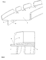
Figure 3a and 3b show perspective views of the aircraft load frame made of a composite material that is finished, impregnated and cured with the jig and the method of the present invention. -
Figure 4 shows a C- shaped preform of the aircraft load frame made of a composite material according to the invention. -
Figure 5 shows an L-shaped preform of the aircraft load frame made of a composite material according to the invention. -
Figure 6 shows one preform of the stabilization rib of the web of the aircraft load frame made of a composite material according to the invention. -
Figure 7 shows a preform of the roving or staple fiber of the aircraft load frame made of a composite material according to the invention. -
Figure 8 shows the integration of the preforms shaping the aircraft load frame made of a composite material according to the invention. -
Figure 9 shows a sectional view of the jig for the manufacture of composite material frames for aircraft according to the invention. -
Figure 10 shows a perspective view of the jig for the manufacture of composite material frames for aircraft according to the invention. -
Figure 11 shows a detail of the stabilization ribs of the web of the composite material frames for aircraft according to the invention. -
Figure 12 shows a general view of the vacuum system of the jig for the manufacture of composite material frames for aircraft according to the invention. - In a first aspect, the present invention relates to a jig for injecting and curing the preforms of an
aeronautic fuselage frame 2 made of a composite material. - The section to be manufactured is formed by a C-shaped preform (
Figure 4 ) and by an L-shaped angular preform 4 (Figure 5 ), in addition todifferent stabilization ribs 5 of the web (Figure 6 ) and apreform 6 of the roving or staple fiber (Figure 7 ). This arrangement of preforms allows the manufacture ofaircraft load frames 2 with the parts for joining them to the following frame integrated therewith, as can be seen inFigure 8 . The preforms are made of fabric and reinforcements with unidirectional tape in the inner flanges to increase their moment of inertia and, consequently, their rigidity. - Likewise, the jig object of the invention comprises the following elements: an injection and
curing jig 7, a vacuum system 8 and a closing and heating system. - The injection and curing jig comprises different members:
- A
tub 10. This is the base element, inside of which the remaining elements shaping thejig 7 as well as thepreforms jig 7 during the heating cycle. - An assembly of
male parts 11. This is the assembly of machined male parts that goes under the C-shaped preform 3. They allow demolding theframe 2 without difficulties. These male parts are longitudinally cut to make demolding and handling easier. - An assembly of
male parts 12. This is the assembly of upper male parts shaping theframe 2 on the side of the outer flange, i.e. the one in contact with the fuselage skin and the legs of the stringers. It copies the entire geometry of the skin on which it rests, as well as the shape of the legs of the stringers, while at the same time it incorporates grooves on its upper surface for the injection of resin. These grooves open into the inlet and outlet boreholes oftub 10. Themale parts 12 are longitudinally cut to make demolding and handling easier. - An assembly of
male parts 13. This is the assembly of upper male parts shaping theframe 2 on the side of the inner flange, i.e., the one in the innermost part of the fuselage and serving to stiffen the section of the mentionedframe 2. The reinforcements with unidirectional tape giving rigidity to theframe 2 are placed on this flange. It incorporates grooves at its inner surface allowing the extraction of the resin. These grooves open into the resin outlet boreholes of thetub 10. - An assembly of
male parts 14. They are the male parts in both sides of thestabilization ribs 5 for stabilizing the web of theframe 2, and therefore, such male parts are placed between themale parts 11. They are provided with a resin outlet channel to allow the correct impregnation of theribs 5. Their design must be such that it allows demolding. -
Cover 15. It is the upper part of thejig 7, sealing saidjig 7 against thetub 10, to the sealing system incorporating saidtub 10. Thecover 15 is planar to ensure in a simple and efficient manner the vacuum level required inside thejig 7. It incorporates thermocouples for the thermal control of thejig 7 during the heating cycle thereof. - The vacuum system 8 comprises the following elements:
- An assembly of sealing
rubbers 16, arranged in several grooves at the upper part of thetub 10. - A system of
hollow silicone tubes jig 7 with thevacuum pump 17 and theresin injection machine 19. - A
vacuum circuit 21. A leak-tight (metallic or non-metallic)tube circuit 23 to which the silicone tubes coming from the injection and curingjig 7 are led, and from which comes anothersilicone 22 tube leading to thevacuum pump 17. It is therefore a circuit arranged over thepress 18 and joining the different resin extraction points of thejig 7 to one other. The connection between thevacuum circuit 21 and thesilicone tubes 20 leading to thejig 7 is made through leak-tight connectors. To prevent the resin inform entering thevacuum system 21, the joining is done through expansion or draining vessels, and the resin would fall on such vessels if it accidentally reached this position. -
Vacuum pump 17. It is able to reach a vacuum level of 0.5 mbar. - According to the concept of the injection and curing
jig 7 detailed in this invention, two processes for closing and heating thejig 7 can be used for the resin injection and curing process: - A
hot plate press 18. It consists of hydraulic or pneumatic presses, with the geometry enveloping all of thoseframes 2 which are to be manufactured, with the following basic operating concept.- i. Pushing cylinders at the upper part of the press, reacting against columns connected to the floor.
- ii. A lower carriage with horizontal movement, for inserting and extracting tools in the press.
- iii. Upper heated plate.
- iv. Lower heated plate.
- v. Pressure and temperature control system with a programmable automaton.
- vi. Insulating hood to prevent heat escape during the heating cycle.
- vii. A bushing system to pass the resin injection and extraction tubes from the injection system to the
jig 7. - viii. A connection system for the thermocouples housed in the
jig 7, such that the programmable automaton controls the different heating areas of the plates of the press, according to the local temperature of thejig 7.
- Injection and curing autoclave. In this case, the autoclave exerts the closing pressure, for which it is necessary to close the
jig 7 with a vacuum lock. The resin injection and extraction tubes must be able to withstand the pressure of the autoclave without collapsing, for which the they will be connected to the bushing of the autoclave to connect said autoclave with the resin injection system. - According to a second aspect, the present invention develops a method of manufacturing composite material load frames for aircraft comprising the following steps:
- 1. Placing and closing the injection and curing
jig 7. - 2. Placing the
jig 7 on the injection and curingpress 18. - 3. Connecting the vacuum system 8.
- 4. Applying pressure to the
press 18, to close thejig 7 and to ensure tightness. - 5. Heating the
jig 7 up to the injection temperature. - 6. Applying vacuum to the
jig 7 though the vacuum system 8. - 7. Injecting the resin.
- 8. Restricting the
silicone tubes 20 once the resin has overflowed through the injection hoses. - 9. Applying compacting pressure to the
injection machine 19, up to 3 bar, i.e. the resin passing through the inlet tube of the jig enters with a pressure of 3 bar. - 10.A heating gradient up to the curing temperature.
- 11.Maintaining the curing temperature.
- 12.Cooling.
- 13.Demolding.
- Those modifications which are comprised in the scope of the following claims can be introduced in the described preferred embodiment.
Claims (8)
- A jig for injecting and curing preforms of an aircraft fuselage composite material frame (2), characterized in that the mentioned jig shapes preforms comprising at least one C shaped preform (3), at least one L shaped angular preform (4), at least one stabilization rib (5) for stabilizing the web of the frame (2) and at least one preform (6) of the roving or staple fiber in the joint between the C shaped preform (3) and the L shaped angular preform (4), and in that the mentioned jig comprises an injection and curing jig (7) injecting and curing resin for the manufacture of the preforms, a vacuum system (8) allowing to shape the previous preforms by means of applying vacuum and a heating and closing system such that the section of the structure of the frames (2) by means of the previous preforms is integreated in one part.
- A jig for injecting and curing preforms of an aircraft fuselage frame (2) according to claim 1, characterized in that the preforms (3, 4, 5 and 6) are manufactured by means of RTM (resin transfer molding) technology.
- A jig for injecting and curing preforms of an aircraft fuselage frame (2) according to any of the previous claims, characterized in that the preforms (3, 4, 5 and 6) comprise fabric and reinforcements with unidirectional tape in the inner flange to increase their moment of inertia and, consequently, their rigidity.
- A jig for injecting and curing preforms of an aircraft fuselage frame (2) according to any of the previous claims, characterized in that the injection and curing jig (7) comprises a tub (10) in which there are placed the remaining elements shaping the jig (7) and the preforms (3, 4, 5 and 6) are placed, one male parts (11) assembly which is placed under the C shaped preform (3), an assembly of upper male parts (12) shaping the frame (2) on the side of the outer flange, an assembly of upper male parts (13) shaping the frame (2) on the side of the inner flange, an assembly of male parts (14) which are arranged on both sides of the stabilization ribs (5) for stabilizing the web of the frame (2) and a cover (15) sealing the jig (7) against the tub (10).
- A jig for injecting and curing preforms of an aircraft fuselage frame (2) according to any of the previous claims, characterized in that the vacuum system (8) comprises an assembly of sealing rubbers (16) arranged at the upper part of the tub (10), one vacuum pump (17), a system of tubes (20,22) joining the jig (7) with a resin injection machine (19) and with the vacuum pump (17), and a vacuum circuit (21) closing the jig (7) and from which the tubes (20, 22) joining said jig (7) with the vacuum pump (17) and with the resin injection machine (19) come out.
- A jig for injecting and curing preforms of an aircraft fuselage frame (2) according to any of the previous claims, characterized in that the heating and closing system comprises a hot plate press (18).
- A jig for injecting and curing preforms of an aircraft fuselage frame (2) according to any of the previous claims, characterized in that the heating and closing system comprises an autoclave.
- A method of manufacturing composite material aircraft fuselage frames (2) comprising the following steps:a) Placing and closing the injection and curing jig (7).b) Placing the jig (7) on the heating and closing system.c) Connecting the vacuum system (8).d) Applying pressure on the closing and heating system to close the jig (7) and ensure tightness.e) Heating the jig (7) to the injection temperature.f) Applying vacuum to the jig (7), through the vacuum system (8).g) Injecting the resin.h) Constricting the tubes (20) once the resin has overflowed through the injection points.i) Applying compacting pressure to the injection machine (19).j) Heating gradient up to the curing temperature.k) Maintaining the curing temperature.l) Cooling.m) Demolding.
Applications Claiming Priority (1)
| Application Number | Priority Date | Filing Date | Title |
|---|---|---|---|
| PCT/ES2007/070042 WO2008104614A1 (en) | 2007-02-28 | 2007-02-28 | Tool and method for producing aircraft ring frames from a composite material |
Publications (2)
| Publication Number | Publication Date |
|---|---|
| EP2127855A1 true EP2127855A1 (en) | 2009-12-02 |
| EP2127855A4 EP2127855A4 (en) | 2015-07-08 |
Family
ID=39714966
Family Applications (1)
| Application Number | Title | Priority Date | Filing Date |
|---|---|---|---|
| EP07730485.5A Withdrawn EP2127855A4 (en) | 2007-02-28 | 2007-02-28 | Tool and method for producing aircraft ring frames from a composite material |
Country Status (4)
| Country | Link |
|---|---|
| US (2) | US20080203601A1 (en) |
| EP (1) | EP2127855A4 (en) |
| CN (1) | CN101743117B (en) |
| WO (1) | WO2008104614A1 (en) |
Cited By (2)
| Publication number | Priority date | Publication date | Assignee | Title |
|---|---|---|---|---|
| DE102010018932B4 (en) * | 2010-04-30 | 2013-06-13 | Airbus Operations Gmbh | Perimeter stiffening for an aircraft fuselage |
| ES2401517R1 (en) * | 2011-05-31 | 2013-08-26 | Airbus Operations Sl | AIRCRAFT NOTEBOOK IN COMPOSITE MATERIAL. |
Families Citing this family (11)
| Publication number | Priority date | Publication date | Assignee | Title |
|---|---|---|---|---|
| DE102008046991A1 (en) † | 2008-09-12 | 2010-03-25 | Mt Aerospace Ag | Load-bearing thick-walled fiber composite structural component and method for its production |
| IT1410977B1 (en) * | 2010-06-14 | 2014-10-03 | Automobili Lamborghini Spa | PROCESS AND DEVICES FOR MANUFACTURING PRODUCTS IN COMPOSITE MATERIALS |
| FR2975035B1 (en) * | 2011-05-10 | 2013-06-14 | Snecma | COMPACTION AND INJECTION MOLD FOR A FIBROUS PREFORM FOR THE MANUFACTURE OF A TURBOMACHINE RECTIFIER BLADE IN COMPOSITE MATERIAL |
| CN103455666A (en) * | 2013-08-12 | 2013-12-18 | 燕山大学 | Contact surface structure of pre-tightening beam and C-shaped plate of plate-frame type hydraulic machine frame |
| EP2883688B1 (en) * | 2013-12-13 | 2021-09-22 | Safran Aero Boosters SA | Composite annular casing of a turbomachine compressor and method for its manufacture |
| ES2681598T3 (en) * | 2014-04-30 | 2018-09-14 | Airbus Operations S.L. | Method and device for manufacturing a part of an aircraft in composite material |
| CN107000335B (en) * | 2014-10-07 | 2020-07-14 | 巴斯夫欧洲公司 | Method and device for producing reinforced plastic parts |
| CN105643958A (en) * | 2014-11-14 | 2016-06-08 | 江西昌河航空工业有限公司 | Forming tool and method for composite |
| DE102016124966B4 (en) * | 2016-12-20 | 2020-09-24 | Deutsches Zentrum für Luft- und Raumfahrt e.V. | Component structure and method of manufacturing the same |
| CN108052974B (en) * | 2017-12-12 | 2022-05-17 | 苏州大学 | Fault diagnosis method, system, equipment and storage medium |
| JP7172887B2 (en) * | 2019-07-02 | 2022-11-16 | トヨタ自動車株式会社 | Underbody structure |
Family Cites Families (50)
| Publication number | Priority date | Publication date | Assignee | Title |
|---|---|---|---|---|
| US2417539A (en) * | 1944-01-20 | 1947-03-18 | Theodore F Aronson | Flexible drill jig |
| US3875275A (en) * | 1958-05-05 | 1975-04-01 | Jerome H Lemelson | Method for molding composite bodies |
| US3088174A (en) * | 1959-01-28 | 1963-05-07 | Gen Motors Corp | Method of producing a reinforced plastic die |
| US4043721A (en) * | 1968-07-11 | 1977-08-23 | Lemelson Jerome H | Composite body molding apparatus |
| US3723584A (en) * | 1969-12-15 | 1973-03-27 | Bischoff Chemical Corp | Method of making an electroformed mold having heat transfer conduits and foam polyurethane foundation |
| LU78535A1 (en) * | 1977-11-17 | 1979-06-13 | Commissariat Energie Atomique | PROCESS FOR MANUFACTURING A COMPOSITE ELEMENT INCLUDING A PLURALITY OF PARTS SOLIDARIZED TO A SUPPORT AND COMPOSITE ELEMENT THUS OBTAINED |
| US4331495A (en) * | 1978-01-19 | 1982-05-25 | Rockwell International Corporation | Method of fabricating a reinforced composite structure |
| US4634563A (en) * | 1982-09-30 | 1987-01-06 | Texas Recreation Corporation | Method of making a composite foamed resin ski |
| US4556375A (en) * | 1982-09-30 | 1985-12-03 | Texas Recreation Corporation | Apparatus for making water skis |
| US4681724A (en) * | 1986-04-28 | 1987-07-21 | United Technologies Corporation | Removable irreversibly shrinking male mandrel |
| US5171510A (en) * | 1988-06-08 | 1992-12-15 | Aerospatiale Societe Nationale Industrielle | Method of producing a frame made of a composite material, especially for the fuselage of an aircraft |
| FR2643015B1 (en) * | 1989-02-14 | 1991-04-19 | Air Liquide | PROCESS FOR THE DEVELOPMENT OF AN ATMOSPHERE FOR THE MANUFACTURE OF HIGH PERFORMANCE COMPOSITE ELEMENTS BY BAG MOLDING |
| US5052906A (en) * | 1989-03-30 | 1991-10-01 | Seemann Composite Systems, Inc. | Plastic transfer molding apparatus for the production of fiber reinforced plastic structures |
| US5174934A (en) * | 1989-04-07 | 1992-12-29 | Sundstrand Corporation | Method of in-situ fabrication of foamed thermoplastic articles and article |
| US5152949A (en) * | 1990-12-19 | 1992-10-06 | United Technologies Corporation | Tooling method for resin transfer molding |
| JP2593772B2 (en) * | 1992-09-01 | 1997-03-26 | 川崎重工業株式会社 | Manufacturing method for composite products |
| JP2588676B2 (en) * | 1992-12-28 | 1997-03-05 | 日本碍子株式会社 | Non-ceramic insulator forming equipment |
| US5393215A (en) * | 1992-12-30 | 1995-02-28 | United Technologies Corporation | Centrifugal resin transfer molding |
| US5595692A (en) * | 1994-09-13 | 1997-01-21 | United Technologies Corporation | Method of repairing resin impregnated articles |
| US5518385A (en) * | 1994-11-09 | 1996-05-21 | United Technologies Corporation | Apparatus for resin transfer molding |
| JP2824025B2 (en) * | 1994-12-27 | 1998-11-11 | 日本碍子株式会社 | Composite insulator and manufacturing method thereof |
| JPH08323807A (en) * | 1995-03-30 | 1996-12-10 | Ngk Insulators Ltd | Manufacture of composite insulator |
| DE19536675C1 (en) * | 1995-09-30 | 1997-02-20 | Deutsche Forsch Luft Raumfahrt | Device and method for producing large-area components according to the RTM method |
| US5824249A (en) * | 1996-02-28 | 1998-10-20 | Dow-Ut Composite Products, Inc. | Modular molding method and associated mold |
| US5876540A (en) * | 1996-05-31 | 1999-03-02 | The Boeing Company | Joining composites using Z-pinned precured strips |
| FR2761001B1 (en) * | 1997-03-24 | 1999-06-25 | Aerospatiale | PLANT FOR MANUFACTURING PARTS IN COMPOSITE MATERIAL, BY RESIN TRANSFER MOLDING |
| US5863452A (en) * | 1997-04-17 | 1999-01-26 | Northrop Grumman Corporation | Isostatic pressure resin transfer molding |
| US6869558B2 (en) * | 1997-12-18 | 2005-03-22 | Thermoplastic Composite Designs, Inc. | Thermoplastic molding process and apparatus |
| DE19845863B4 (en) * | 1998-10-05 | 2005-05-19 | Deutsches Zentrum für Luft- und Raumfahrt e.V. | Structural element with large unidirectional stiffness |
| US7681835B2 (en) * | 1999-11-18 | 2010-03-23 | Rocky Mountain Composites, Inc. | Single piece co-cure composite wing |
| US6638466B1 (en) * | 2000-12-28 | 2003-10-28 | Raytheon Aircraft Company | Methods of manufacturing separable structures |
| US6840750B2 (en) * | 2001-06-11 | 2005-01-11 | The Boeing Company | Resin infusion mold tool system and vacuum assisted resin transfer molding with subsequent pressure bleed |
| WO2003013820A1 (en) * | 2001-08-07 | 2003-02-20 | Toray Industries, Inc. | Method for producing upsized frp member |
| GB0127154D0 (en) * | 2001-11-13 | 2002-01-02 | Bae Systems Plc | A mould tool |
| US6939505B2 (en) * | 2002-03-12 | 2005-09-06 | Massachusetts Institute Of Technology | Methods for forming articles having very small channels therethrough, and such articles, and methods of using such articles |
| US6958105B2 (en) * | 2002-08-08 | 2005-10-25 | Airbus Deutschland Gmbh | Automated fabrication of an integral fiber reinforced composite structural component using a positioning and assembly support |
| US6723273B2 (en) * | 2002-09-11 | 2004-04-20 | Keith Johnson | Curable liquid sealant used as vacuum bag in composite manufacturing |
| EP1473131A3 (en) * | 2003-04-30 | 2007-01-03 | Airbus Deutschland GmbH | Method for making textile preforms from textile half-products |
| US7305308B2 (en) * | 2003-07-01 | 2007-12-04 | Northwestern University | Gas flow method for detection of preform defects based on transient pressure measurement |
| JP4299605B2 (en) * | 2003-07-23 | 2009-07-22 | カルソニックカンセイ株式会社 | Resin insert molding jig for metal plate member and resin insert molding method for metal plate member using the same |
| US7029267B2 (en) * | 2003-10-23 | 2006-04-18 | Saint- Gobain Technical Fabrics Canada, Ltd | Reusable vacuum bag and methods of its use |
| EP2565007A1 (en) * | 2004-02-17 | 2013-03-06 | Toray Industries, Inc. | Rtm molding method and device |
| US7160498B2 (en) * | 2004-03-08 | 2007-01-09 | Tracker Marine, L.L.C. | Closed molding tool |
| DE102004025381B4 (en) * | 2004-05-24 | 2014-01-23 | Airbus Operations Gmbh | Window frame for aircraft |
| DE102005008479B4 (en) * | 2005-02-24 | 2011-07-07 | Airbus Operations GmbH, 21129 | Arrangement and method for producing a component |
| CA2550474A1 (en) * | 2005-06-20 | 2006-12-20 | Magna International Inc. | Rtm auto-vent process |
| US8087916B2 (en) * | 2005-12-15 | 2012-01-03 | Cemedine Henkel Co., Ltd. | Holding jig for a foamable material |
| CN101448629B (en) * | 2005-12-29 | 2011-08-17 | 空客西班牙公司 | Method and tool for manufacturing composite annular frame |
| US7862322B2 (en) * | 2006-04-25 | 2011-01-04 | Florida State University Research Foundation | Resin infusion between double flexible tooling system |
| US20080136060A1 (en) * | 2006-12-08 | 2008-06-12 | Gkn Westland Aerospace, Inc. | System and method for forming and curing a composite structure |
-
2007
- 2007-02-28 WO PCT/ES2007/070042 patent/WO2008104614A1/en active Application Filing
- 2007-02-28 CN CN200780052728.7A patent/CN101743117B/en not_active Expired - Fee Related
- 2007-02-28 EP EP07730485.5A patent/EP2127855A4/en not_active Withdrawn
- 2007-05-01 US US11/799,324 patent/US20080203601A1/en not_active Abandoned
-
2010
- 2010-11-08 US US12/941,774 patent/US8329077B2/en active Active
Non-Patent Citations (1)
| Title |
|---|
| See references of WO2008104614A1 * |
Cited By (2)
| Publication number | Priority date | Publication date | Assignee | Title |
|---|---|---|---|---|
| DE102010018932B4 (en) * | 2010-04-30 | 2013-06-13 | Airbus Operations Gmbh | Perimeter stiffening for an aircraft fuselage |
| ES2401517R1 (en) * | 2011-05-31 | 2013-08-26 | Airbus Operations Sl | AIRCRAFT NOTEBOOK IN COMPOSITE MATERIAL. |
Also Published As
| Publication number | Publication date |
|---|---|
| CN101743117A (en) | 2010-06-16 |
| CN101743117B (en) | 2015-02-18 |
| US20080203601A1 (en) | 2008-08-28 |
| WO2008104614A1 (en) | 2008-09-04 |
| US8329077B2 (en) | 2012-12-11 |
| US20110049744A1 (en) | 2011-03-03 |
| EP2127855A4 (en) | 2015-07-08 |
Similar Documents
| Publication | Publication Date | Title |
|---|---|---|
| EP2127855A1 (en) | Tool and method for producing aircraft ring frames from a composite material | |
| US8771575B2 (en) | Methods and systems for forming reinforced composite articles having variable thickness corners | |
| US8500085B2 (en) | Method for manufacturing a composite fiber component for aerospace | |
| US7530530B2 (en) | Assembly for securing a stringer to a substrate | |
| US6861017B1 (en) | Method for forming composite parts from volatile-emitting materials using breathable tooling | |
| US7544261B1 (en) | Process and tools for manufacturing composite ring frames | |
| RU2445206C2 (en) | Method of producing structural component from composite material reinforced by fibers using formed core, and formed core | |
| CA2002302C (en) | Tool for moulding self-stiffened panels made from a composite material | |
| US8337740B2 (en) | Reinforced internal composite structures | |
| EP2357075B1 (en) | Method for manufacturing a complex-geometry panel with pre-impregnated composite material | |
| RU2376196C2 (en) | Aircraft window frame and method of its fabrication | |
| CA2713115A1 (en) | Method for joining two fuselage sections by creating a transverse butt joint as well as a transverse butt joint connection | |
| CN107471655A (en) | For manufacturing the method and device of the structure member applied to aircraft or spacecraft | |
| US20110156305A1 (en) | Method and device for manufacturing a fiber composite component with an integral structural design | |
| EP2774854B1 (en) | An improved monolithic fan cowl of an aircraft engine and a manufacturing method thereof | |
| EP3797963B1 (en) | Method and tool for manufacturing a composite aircraft window frame | |
| US10549490B2 (en) | Method for manufacturing a stiffened panel made from composite material | |
| US8870117B2 (en) | Composite aircraft frame | |
| CN110884161A (en) | Method for manufacturing curved omega stringers and Z-shaped composite stringers and method for manufacturing composite stiffened panel having curvature | |
| US8512620B2 (en) | Method and device for the manufacture of a component | |
| EP2736703A1 (en) | A device for the manufacture of a bonded component with fibre-reinforced plastics and also a method | |
| EP3744511A1 (en) | Composite forming station |
Legal Events
| Date | Code | Title | Description |
|---|---|---|---|
| PUAI | Public reference made under article 153(3) epc to a published international application that has entered the european phase |
Free format text: ORIGINAL CODE: 0009012 |
|
| 17P | Request for examination filed |
Effective date: 20090918 |
|
| AK | Designated contracting states |
Kind code of ref document: A1 Designated state(s): AT BE BG CH CY CZ DE DK EE ES FI FR GB GR HU IE IS IT LI LT LU LV MC NL PL PT RO SE SI SK TR |
|
| RIN1 | Information on inventor provided before grant (corrected) |
Inventor name: MARTIN MARTIN, JESUS MANUEL Inventor name: MARQUEZ LOPEZ, IGNACIO JOSE |
|
| DAX | Request for extension of the european patent (deleted) | ||
| RA4 | Supplementary search report drawn up and despatched (corrected) |
Effective date: 20150610 |
|
| RIC1 | Information provided on ipc code assigned before grant |
Ipc: B64C 1/00 20060101ALI20150604BHEP Ipc: B29C 70/48 20060101AFI20150604BHEP Ipc: B29D 99/00 20100101ALI20150604BHEP |
|
| 17Q | First examination report despatched |
Effective date: 20170426 |
|
| STAA | Information on the status of an ep patent application or granted ep patent |
Free format text: STATUS: THE APPLICATION IS DEEMED TO BE WITHDRAWN |
|
| 18D | Application deemed to be withdrawn |
Effective date: 20170907 |
|
| RIC1 | Information provided on ipc code assigned before grant |
Ipc: B29D 99/00 20100101ALI20150604BHEP Ipc: B64C 1/00 20060101ALI20150604BHEP Ipc: B29C 70/48 20060101AFI20150604BHEP |
|
| RIC1 | Information provided on ipc code assigned before grant |
Ipc: B29C 70/48 20060101AFI20150604BHEP Ipc: B64C 1/00 20060101ALI20150604BHEP Ipc: B29D 99/00 20100101ALI20150604BHEP |