EP2127224B1 - Privates virtuelles lan zum spanning eines öffentlichen netzwerks zwecks verbindung arbiträrer hosts - Google Patents
Privates virtuelles lan zum spanning eines öffentlichen netzwerks zwecks verbindung arbiträrer hosts Download PDFInfo
- Publication number
- EP2127224B1 EP2127224B1 EP08705920.0A EP08705920A EP2127224B1 EP 2127224 B1 EP2127224 B1 EP 2127224B1 EP 08705920 A EP08705920 A EP 08705920A EP 2127224 B1 EP2127224 B1 EP 2127224B1
- Authority
- EP
- European Patent Office
- Prior art keywords
- network
- graph
- client
- peer
- ivlan
- Prior art date
- Legal status (The legal status is an assumption and is not a legal conclusion. Google has not performed a legal analysis and makes no representation as to the accuracy of the status listed.)
- Active
Links
Images


Classifications
-
- H—ELECTRICITY
- H04—ELECTRIC COMMUNICATION TECHNIQUE
- H04L—TRANSMISSION OF DIGITAL INFORMATION, e.g. TELEGRAPHIC COMMUNICATION
- H04L67/00—Network arrangements or protocols for supporting network services or applications
- H04L67/01—Protocols
- H04L67/10—Protocols in which an application is distributed across nodes in the network
- H04L67/104—Peer-to-peer [P2P] networks
-
- H—ELECTRICITY
- H04—ELECTRIC COMMUNICATION TECHNIQUE
- H04L—TRANSMISSION OF DIGITAL INFORMATION, e.g. TELEGRAPHIC COMMUNICATION
- H04L12/00—Data switching networks
- H04L12/28—Data switching networks characterised by path configuration, e.g. LAN [Local Area Networks] or WAN [Wide Area Networks]
- H04L12/46—Interconnection of networks
- H04L12/4641—Virtual LANs, VLANs, e.g. virtual private networks [VPN]
-
- H—ELECTRICITY
- H04—ELECTRIC COMMUNICATION TECHNIQUE
- H04L—TRANSMISSION OF DIGITAL INFORMATION, e.g. TELEGRAPHIC COMMUNICATION
- H04L67/00—Network arrangements or protocols for supporting network services or applications
- H04L67/01—Protocols
- H04L67/10—Protocols in which an application is distributed across nodes in the network
- H04L67/104—Peer-to-peer [P2P] networks
- H04L67/1087—Peer-to-peer [P2P] networks using cross-functional networking aspects
- H04L67/1093—Some peer nodes performing special functions
-
- H—ELECTRICITY
- H04—ELECTRIC COMMUNICATION TECHNIQUE
- H04L—TRANSMISSION OF DIGITAL INFORMATION, e.g. TELEGRAPHIC COMMUNICATION
- H04L61/00—Network arrangements, protocols or services for addressing or naming
- H04L61/45—Network directories; Name-to-address mapping
- H04L61/4505—Network directories; Name-to-address mapping using standardised directories; using standardised directory access protocols
- H04L61/4511—Network directories; Name-to-address mapping using standardised directories; using standardised directory access protocols using domain name system [DNS]
-
- H—ELECTRICITY
- H04—ELECTRIC COMMUNICATION TECHNIQUE
- H04L—TRANSMISSION OF DIGITAL INFORMATION, e.g. TELEGRAPHIC COMMUNICATION
- H04L61/00—Network arrangements, protocols or services for addressing or naming
- H04L61/50—Address allocation
- H04L61/5007—Internet protocol [IP] addresses
-
- H—ELECTRICITY
- H04—ELECTRIC COMMUNICATION TECHNIQUE
- H04L—TRANSMISSION OF DIGITAL INFORMATION, e.g. TELEGRAPHIC COMMUNICATION
- H04L63/00—Network architectures or network communication protocols for network security
- H04L63/02—Network architectures or network communication protocols for network security for separating internal from external traffic, e.g. firewalls
- H04L63/0272—Virtual private networks
-
- H—ELECTRICITY
- H04—ELECTRIC COMMUNICATION TECHNIQUE
- H04L—TRANSMISSION OF DIGITAL INFORMATION, e.g. TELEGRAPHIC COMMUNICATION
- H04L63/00—Network architectures or network communication protocols for network security
- H04L63/10—Network architectures or network communication protocols for network security for controlling access to devices or network resources
- H04L63/104—Grouping of entities
-
- H—ELECTRICITY
- H04—ELECTRIC COMMUNICATION TECHNIQUE
- H04L—TRANSMISSION OF DIGITAL INFORMATION, e.g. TELEGRAPHIC COMMUNICATION
- H04L67/00—Network arrangements or protocols for supporting network services or applications
- H04L67/01—Protocols
- H04L67/10—Protocols in which an application is distributed across nodes in the network
- H04L67/104—Peer-to-peer [P2P] networks
- H04L67/1044—Group management mechanisms
- H04L67/1046—Joining mechanisms
Definitions
- P2P Peer-to-peer
- P2P networks enable client machines to communicate directly with each other, without the need for a hosted infrastructure or dedicated servers.
- P2P networking offers several advantages, related at least in part to easy setup, efficient data transfer, and network resilience. While initially conceived and popularized for the purpose of file sharing, P2P has now emerged as a general paradigm for the construction of resilient, large-scale, distributed services and applications in the Internet.
- overlay networks can provide network solutions that enable hosts to join a private named P2P "overlay" network.
- Nodes can identify the overlay networks by name, and automatically locate other active participants within the overlay.
- active nodes can create and self-organize communication paths, enabling resilient communication and low-latency data transfer.
- overlay networks can provide a variety of services, including messaging and database replication, for communication among active nodes.
- the network is only available to applications that specifically program to the overlay network APIs (meaning that the overlay cannot be used for general network communication). Additionally, it is difficult for multiple applications to share the same overlay network, and users have no direct standard way of configuring and managing overlay networks.
- VPNs virtual private networks
- VLANs virtual local area networks
- Users configure and launch VPNs (whether over IPSec, PPTP, L2TP/IPSec, etc.) that establish a point-to-point (client-server) connection over a public network (e.g., the Internet) or some other physical media.
- the VPN is exposed as a virtual network interface that effectively hides the point-to-point "overlay" connection, and rather, exposes seamless IP routability between the VPN client, VPN server, and networks exposed by the VPN server.
- VLANs illustrate another example of seamless virtual networking.
- network switches In a VLAN, network switches aggregate a collection of physical links into a logical subnet by specially tagging (e.g., IEEE 802.1q) Ethernet frames. Hosts on a VLAN form a single broadcast domain where network switches take responsibility for forwarding packets as needed to create the virtual subnet semantics for the client hosts.
- tagging e.g., IEEE 802.1q
- IPOP a system for creating virtual IP networks on top of a P2P overlay.
- IPOP enables seamless access to Grid resources spanning multiple domains by aggregating them into a virtual IP network that is completely isolated from the physical network.
- the virtual IP network provided by IPOP supports deployment of existing IP-based protocols over a robust, self-configuring P2P overlay.
- IPOP virtual IP address space is routable within the PCP overlay, however it is decoupled from the address space of the physical Internet infrastructure.
- the host administrator is required to set up a tap device in the host, and bring it up with an IP address that is unique in the virtual IP address space.
- IPOP runs on the host as a P2P node whose address is the 160 bit SHA-1 hash of IP address of the tap device.
- FUJITA N ET AL "A DYNAMIC TOPOLOGY AND ROUTING MANAGEMENT STRATEGY FOR VIRTUAL IP NETWORKS", IEICE TRANSACTIONS ON COMMUNICATIONS, COMMUNICATIONS SOCIETY, TOKYO, JP, vol. E89B, no. 9 , discloses a P2P-XBone, in which a P2P protocol such as DHT drive the topology and the routing table of a virtual IP network consistent with its neighbor node state. It is further described how to extend both the existing X-Bone system and P2P mechanisms to achieve interworking between them, in particular how to establish IP tunnels corresponding to neighbor nodes in the DHT protocol.
- the disclosed architecture provides a server-less peer-to-peer virtual private network, referred to hereinafter as an Internet virtual LAN (IVLAN), based on the overlay network technology.
- IVLAN Internet virtual LAN
- the IVLAN enables the creation of a virtual IP network having the properties of a standard local area network without requiring a central server.
- This technology enables applications normally running only in a single physical network to actually be used in a completely distributed way over networks such as the Internet.
- the system can also enable IP applications to operate on devices communicating through multi-hop ad hoc communication links (e.g., Wi-Fi, Bluetooth, etc.).
- the architecture is described in the context of an existing WindowsTM P2P SDK (software development kit) that enables the formation of a network graph or overlay network.
- a WindowsTM P2P SDK graphing component can be extended with a routing protocol that allows messages to be routed to any node participating in the overlay network.
- a virtual IP layer based on a TAP or virtual network interface is built to provide the illusion of a local area network.
- the virtual network has all the characteristics of a standard local area network and supports IPv4 and IPv6 unicast, multicast, and broadcast packets. Accordingly, the architecture allows applications normally restricted to a local area network to be run over the Internet without any modification.
- the disclosed architecture combines the technologies of peer-to-peer (P2P) overlay networks, virtual private networks (VPNs), and virtual local area networks (VLANs) to form a novel entity that will be referred to throughout the description as an Internet virtual LAN (IVLAN).
- IVLAN Internet virtual LAN
- Internet is used, it is to be understood that the disclosed architecture is not limited to the Internet, but can also be applied to any public network.
- IVLANs are private virtual networks comprised of arbitrary hosts connected over the Internet.
- a group of nodes form an overlay network.
- this overlay network can have one or more of the following three properties. Similar to a VPN, the overlay network supports IP routing.
- the overlay network supports some form of routing, and is not limited to only IP routing.
- the IVLAN is exposed as a network interface that applications can access using standard Winsock calls (for purposes of this discussion, each host is assigned a private IPv4 and/or IPv6 address within the context of the overlay network).
- the IVLAN supports broadcast/multicast semantics. In other words, the private addresses (e.g., IPv6) assigned inside the overlay share a common network address prefix.
- IVLANs can be authenticated on a per-connection basis, thus, the IVLANs are private. However, it is not necessary for each host to a priori know the identity of every other host. Instead, it is sufficient for each host to simply validate that its peers are authorized (and hence, trusted) members of the IVLAN. By way of analogy, IVLANs bring to the Internet the semantic equivalent of "direct connect" or multi-connect or routing connect found in cellular networks.
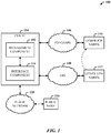
- FIG. 1 illustrates a computer-implemented networking system 100 for extending private network access into the public domain.
- the system 100 includes a management component 102 of a client 104 for creating and managing a peer-to-peer (P2P) graph 106 that overlays a virtual network 108 (e.g., a virtual private network (VPN)) for P2P communications between the client 104 and other arbitrary nodes 110.
- P2P peer-to-peer
- VPN virtual private network
- the client 104 can also include an interface component 114 for exposing the arbitrary P2P nodes 110 of the P2P graph 106 to a public node 116 disposed on a public network 118.
- the other VPN nodes 112 can also include the management component 102 and interface component 114 in support of joining the P2P graph 106 as part of the other P2P nodes 110 and communicating according to a peer technology, not only among the other P2P nodes and the client 104, but also to the public node 116.
- the interface component 114 exposes the P2P graph 106 to the public node 116 as a virtual interface.
- the management component 102 is created on a physical interface IP address, wherein the IP address is an IPv4 and/or an IPv6 address.
- the interface component 114 includes a virtual network interface card (VNIC) controlled by a VNIC driver, where the VNIC driver exposes a miniport driver and a file stream interface for passing IP packets between a VNIC and the management component 102 for routing and transmission to the arbitrary nodes of the P2P graph 106.
- VNIC virtual network interface card
- the management component 102 includes a routing protocol for enabling multi-hop message routing over the P2P graph 106.
- the management component 102 includes a user-level application for controlling and configuring the VNIC driver, and communicating IP packets on behalf of the VNIC. Other aspects of the management component 102 facilitate at least one of multicast traffic or broadcast traffic and traversal of at least one of a firewall system or a network address translation system.
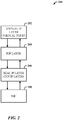
- FIG. 2 illustrates the logical architecture 200 of the disclosed IVLAN capability.
- the architecture 200 includes a virtual IP layer 202 for handling virtual TCP/IP, over a P2P layer 204 for processing P2P traffic.
- the virtual layer 202 and P2P layer 204 are provided over the real IP layer 206 and a physical interface 208 (e.g., a NIC).
- a physical interface 208 e.g., a NIC
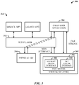
- FIG. 3 illustrates a more detailed diagram of the IVLAN architecture 300 for a client.
- the architecture 300 includes a VNIC 302 and a user-level IVLAN application 304.
- the VNIC 302 includes a VNIC driver 306 (also referred to as the IVLAN driver) that exposes a standard NDIS (network drive interface specification, e.g., version 5.1) miniport driver interface 308 and a file stream interface 310.
- NDIS network drive interface specification, e.g., version 5.1
- a TCP/IP protocol stack (or layer) 312 exchanges packets with the IVLAN driver 306, enabling existing applications 314 to run over the IVLAN, and communicate with other P2P graph nodes, or communicate over a physical NIC 316 with public nodes.
- the IVLAN driver 306 passes these IP packets to the IVLAN application for routing and transmission over the P2P graph.
- the IVLAN user application 304 controls and configures the VNIC driver 308 and, sends and receives IP packets on behalf of the VNIC 302.
- the IVLAN application 304 uses, in one embodiment, the WindowsTM P2P SDK (software development kit) to form and maintain an overlay network (or graph) connecting all nodes of an IVLAN.
- the Windows P2P SDK can support message flooding through the graph links, point-to-point TCP connections for direct communication between participating nodes, and a replicated database among graph nodes.
- the IVLAN user application 304 extends this behavior by introducing a routing protocol enabling multi-hop message routing over the P2P graph.
- the ad hoc on-demand distance vector routing protocol is employed because the protocol minimizes control traffic overhead and maximizes performance. AODV's on-demand nature enables quick reaction to changes in the graph conditions. Additionally, the protocol always finds the routes providing the minimum latency between two nodes.
- the IVLAN application 304 When the IVLAN application 304 starts, it enables the VNIC driver interface 308 and assigns IPv4 and IPv6 addresses to the VNIC 302. Thus, every Ethernet packet arriving from the TCP/IP stack 312 and targeting the VNIC interface 308 is caught by the VNIC driver 306 and forwarded to the IVLAN user application 304 through the file stream interface 310 using CreateFile(), ReadFile(), and WriteFile() APIs, for example.
- the file stream interface 310 interface allows an IVLAN user application 304 to directly communicate with an in-kernel device driver through a file name exposed in the file system.
- Ethernet packets are then encapsulated inside P2P messages and passed to the P2P graph for routing to the designated destination (via TCP/IP connections over the physical NIC 316). Only IP packets are routed in the graph while non-IP Ethernet packets (e.g., ARP-address resolution protocol, IPv6 neighbor solicitations) are handled locally or simply dropped.
- non-IP Ethernet packets e.g., ARP-address resolution protocol, IPv6 neighbor solicitations
- the IVLAN user application receives the traffic through neighbor nodes in the graph.
- the destination extracts the Ethernet packets from the received P2P messages and passes the packets to the associated VNIC.
- the VNIC forwards the Ethernet packets into the TCP/IP stack as if the packets had arrived from a physical network controller 316.
- FIG. 4 illustrates an exemplary communication between two IVLAN nodes.
- a source legacy application (denoted LEGACY APP2) of a source node initiates packet traffic to a destination application of a destination node.
- the packet traffic is intercepted by the source VNIC and routed by the source P2P user application (denoted IVLAN USER APP) through the source TCP/IP layer to the source physical NIC (denoted PHYSICAL NIC).
- the source physical NIC routes the traffic through the graph to a neighbor physical NIC of a neighbor node, which routes the traffic to the neighbor P2P user application.
- the neighbor P2P application checks the P2P encapsulation on the packets and returns the traffic to the neighbor physical NIC for routing over the graph to a destination physical NIC.
- the destination physical NIC routes the traffic up the destination stack to a destination P2P user application for routing through the destination VNIC to an intended destination legacy application.
- the disclosed architecture provides a solution for legacy applications leveraging a standard communication layer such as IP could be supported over a P2P network overlay to provide a serverless VPN.
- the architecture enables many applications normally running only in a single physical network to actually be used in a completely distributed way.
- the disclosed architecture enables IP applications to be used over a set of devices communicating with each other through multi-hop ad hoc and heterogeneous communication links (Wi-Fi, Bluetooth, etc).
- FIG. 5 illustrates a VPN in a heterogeneous network environment 500.
- different devices e.g., PCs, laptops, PDAs, etc.
- heterogeneous links Wi-Fi, Bluetooth, etc.
- PC1 and PC2 are connected via a wire Ethernet switch 504 and have IP addresses 192.168.0.23 and 192.168.0.56, respectively.
- PC2 also has a wireless (e.g., Wi-Fi) adapter through which PC2 is connected to a Laptop in the ad hoc wireless network 502.
- the Wi-Fi adapter in PC2 is assigned IP address 192.168.1.3.
- the Wi-Fi adapter in the Laptop has IP address 192.168.1.21.
- the Laptop can also be connected to a PDA1 using Wi-Fi in an ad hoc manner.
- PDA1 has an IP address 192.168.1.6.
- the Laptop can also have a Bluetooth adapter through which it is connected to a PDA2 and a PDA3 in a personal area network (PAN).
- PAN personal area network
- the Laptop, PDA2 and PDA3 have IP addresses 192.168.0.1, 192.168.0.2 and 192.168.0.5, respectively.
- any of the devices can communicate with all the other devices in the current scenario.
- PC1 cannot communicate with the Laptop or PDA1, PDA2 and PDA3.
- PDA1 cannot communicate with PDA2, PDA3, PC1 and PC2.
- the problem is that the devices do not belong to a single LAN so that applications relying on the ability to discover other nodes through broadcast and/or multicast may not run.
- a P2P-based virtual IP network 504 provides a benefit.
- P2P-based virtual IP network 504 provides a benefit.
- all the devices become part of a single virtual LAN (or subnet), and thus, can communicate with all the members.
- the IP packets are routed among the devices over the P2P overlay.
- FIG. 6 illustrates a system 600 that employs the disclosed IVLAN 602 over the Internet 604.
- the IVLAN 602 can also provide connection among networked computers with Internet access. All the computers connected to the IVLAN 602 will be able to access each other just as in the LAN, even though the computers are behind router/firewall/NAT devices and only have private IP addresses.
- the uniqueness of the IVLAN 602 compared with a traditional VPN is the serverless and non-centralized nature. This enables a handful of applications to run over IVLAN 602 which could not be run otherwise.
- an IVLAN can be used to create a virtual LAN between computers connected through the Internet, thus, enabling the computers to play multiplayer games or to run applications that can only be run in a local network.
- the IVLAN 602 can also be used for business needs of organizations. For organizations needing a VPN to connect multiple branch offices, the IVLAN 602 can be used as a serverless VPN. Otherwise, using a traditional VPN solution requires finding a fixed public IP address and the hosting a VPN server in each office. Additionally, there is neither a central bottleneck nor a single point of failure when using the IVLAN 602.
- the IVLAN 602 also enables the use of remote access software without the need of knowing the public IP address or requiring the need for changing the router or firewall settings to map a port to the PC. This is very convenient with the IVLAN 602. As long as the computers are part of the IVLAN 602 using the same peer IDs, the computers can communicate with each other using the peer IDs as computer names.
- IP addresses Computers on the Internet are given dynamic IP addresses through DHCP (dynamic host configuration protocol), shared or filtered IP addresses through NAT (network address translation) devices, or IP addresses that are very hard to reach due to firewalls. Creating TCP/IP communication under such conditions is either impossible or requires elaborate application-level ruses to bypass these restrictions. TCP/IP sockets and server sockets also depend on the DNS (domain name server) to resolve human-friendly host names into the IP addresses.
- DNS domain name server
- the standard DNS does not deal well with the computers that have filtered or dynamic IP addresses and updates take too long to propagate. Developers who wish to create applications that extend DNS into new directions, such as storing instant messaging usernames and presence information in the DNS, are stymied by the DNS system's technical and political issues.
- a peer wishing to become server simply publishes the name record for the domain name the peer wants and creates a server socket listening at a port that other peers should use to contact. Other peers can now directly open client socket connections to the peer.
- This P2P-based Internet brings many advantages.
- domain names could have any form such as MyTestDomain19 , AlphaBravoCharlie or Hollywood-Movies or traditional www.mytest-domain.com.
- one or more peers can publish the same DNS name. In that case some of the client requests to a domain published by two or more peers can be handled by some peers and the rest by some other peers. This is analogous to the DNS round-robin where one host name resolves to many different IP addresses to help load balancing.
- the service ports for a given host name can be distributed across many different peers around the world.
- One peer could be hosting port 80 to serve web pages while some other peer could be hosting port 3000 for instant messaging.
- Every node in the virtual IP network should be able to get a unique IP address.
- the following schemes can be used to assign IP addresses to the VNIC interface and to map IP addresses to peer IDs.
- a peer ID can be used as an IP address for the VNIC.
- the advantage with this scheme is that it is the simplest scheme.
- an administrator is required to setup a tap device in the host and bring it up with an IP address that is unique in the virtual IP address space. Since all the communication on the P2P network is based on peer ID (or node ID), a mechanism is needed to map IP addresses to peer IDs (or node IDs).
- a second scheme uses a dynamic unique IP as published record. This second scheme uses the ability of the P2P graph to maintain a replicated database in order to publish the list of used IP addresses.
- a joining peer first checks its local database for a valid IP address record published previously by itself, and if one is found, assigns that IP address to its VNIC. If a joining peer does not find any self-published valid IP address record, then the joining peer checks its local database for all the IP address records published by all the nodes and then chooses a random IP address not found in any of the published IP records. The joining peer publishes this new IP address record in the form of " ⁇ new_IP > : ⁇ random_number >" with an expiry equal to TEMP_IP_EXPIRY (e.g., one min). The random_number could be the node ID of the joining node or hash of peer ID of joining node.
- the joining node assumes that nobody is using this address and permanently assigns it to the joining node's VNIC.
- the node also publishes the IP address record in the graph with a longer expiry time (e.g., seven days).
- a longer expiry time e.g., seven days.
- the node having published the temporary IP record with random_number nearer to ZERO will win, and the other node will select another random IP address and then repeat the whole process.
- Each peer after obtaining a successful IP address, publishes its IP address record in the graph with an expiry time (e.g., seven days). In case the peer is online and the IP address record published by the peer is about to expire, the peer again republishes/updates the IP address record with a new expiry time.
- This second scheme has several advantages. First, compared with the first scheme, a user does not have to use a peer ID in the form of an IP address, and thus, can use any arbitrary peer ID. Secondly, the user simply has to ensure that a unique peer ID is being used and does not have to bother about uniqueness of IP address. The unique peer ID is easier to ensure than unique IP address because any arbitrary string can be used as peer ID. Thus, this second scheme is suitable for users having no or little knowledge about networking, as compared to the first scheme in which each user has to ensure that the peer ID in the form of IP address should have same network ID but unique host ID.
- ARP requests are used with IPv4 to resolve a destination IP address to a MAC (media access control) address when the address is in the same subnet as the address of the resolving node.
- ARP requests are broadcast at the link layer and a possible way to support ARP requests would be to use the flooding support of the graph for broadcasting.
- ARP requests can be handled locally by each node inside the VNIC driver.
- the MAC addresses for the different VNIC are derived by a static algorithm from the virtual IP address associated to the node.
- A.B.C.D e.g., 192.168.100.35
- the driver creates an ARP reply in which the MAC address for the requested IP address is generated locally.
- the same mechanism can be employed to handle ICMP v6 neighbor solicitations when the virtual network uses IPv6 addresses and needs to resolve such addresses to MAC addresses.
- MAC addresses are generated from IP addresses by prefixing 00-FF at the beginning of the IP addresses.
- the generated MAC address is 00-FF-C0-A8-64-23.
- Dynamic name resolution of a name to an IP address is something that users have been used to, and hence, should be supported inside the virtual IP network.
- the traditional mechanism used for name resolution is DNS.
- DNS name resolution mechanism
- One mechanism for publishing names uses the support of the graph to publish name resolution records.
- a peer node adds a name record in the graph, the record is automatically flooded to all the nodes in the virtual network and stored in their database.
- Each name resolution record can have an associated expiration time (e.g., seven days).
- Each node is responsible for republishing/updating the name resolution record before its expiration.
- IVLAN architecture is an alternative P2P domain name system which responds to updates much quicker than standard DNS.
- the IVLAN provides P2P-based name resolution. Since P2P name resolution does not use the DNS system, host names can be any string. Additionally, a peer can publish one or several names corresponding to different websites or web services.
- the standard name resolver implemented in the TCP/IP stack in the operating system may not be aware of the underlying P2P graph so the graph cannot be used directly to resolve names.
- the resolver first checks the local name for mapping from name to IP address, then checks the hosts file for the mapping, and if not found, then sends the DNS query to the DNS server.
- the following two schemes can be used to resolve network names to IP addresses, and then further, to peer IDs.
- a first resolving scheme uses a host file.
- each peer maintains a list (called NameList or NL ) of peer IDs, IP addresses, and name records published by all the peers.
- NameList a list of peer IDs, IP addresses, and name records published by all the peers.
- Nr a new name record published by a peer having peer ID Pid and having a unique IP address IPr
- the peer also inserts an entry in the host file.
- a name record is expired or deleted then the entry is also deleted from the NL and hosts file.
- FIG. 7 illustrates a system 700 that employs a local DNS resolver component 702 built inside the IVLAN for name resolution over an IVLAN graph.
- each peer implements the local DNS resolver component 702 as part of the IVLAN user application 304 to resolve all the DNS requests locally.
- the resolver component 702 maintains an NL list 704 of peer IDs, IP addresses, and name records published by all the peers, and provides updates through the record flooding mechanism of the graph.
- an arbitrary IP address is fixed for a virtual DNS server which is then not used by any peer present in the virtual network.
- a name resolution (DNS) request is generated for a name Nr
- the VNIC 302 receives the request from the TCP/IP stack 312 and forwards the request to the IVLAN application 304.
- the IVLAN user application 304 checks all the IP packets received from the local VNIC 302 and if the IP packet is a DNS request, the user application 304 passes the DNS request to the local DNS resolver component 702.
- the local DNS resolver component 702 goes through the list 704 of published names ( NL ) and replies with the IP address IPr assigned to peer (having peer ID IP ) which publishes the name record Nr. Thereafter, any IP packet received for the destination IP IPr is forwarded to the peer having peer ID PI.
- a difference between this second resolving scheme and the previous scheme is that here, multiple peers can publish a single domain name, and the local DNS resolver can route some of the requests to one peer and some requests to other peers for load balancing. Additionally, changing the hosts file is not suitable because if the IVLAN graph terminates unexpectedly then the name record entries entered in the hosts file will remain there and the file will not be restored to its original form. Note that name resolution is also supported through multicast DNS, which uses the ability of the IVLAN to support multicast semantics.
- One of the many benefits of overlaying IP on a P2P network is that routing over the overlay can cross firewalls and NATs. This is achieved because all the routing of IP packets (of virtual IP network) is done by a routing manager introduced in the graphing component of P2P SDK. The routing manager routes all the IP packets (of virtual IP network) over the P2P graph, and thus, once a node is part of P2P graph then it is possible to send data or communicate over virtual IP network to any other node in the graph even if behind NAT or firewall in physical IP network.
- An advantage of overlaying IP on a P2P network is device mobility.
- two devices can only communicate with each other if the corresponding IP addresses are known. If during communication any one of the device changes its IP address to some other random IP address then the communication breaks. The second device then needs to know the new IP address of the first device for communication to proceed.
- the disclosed IVLAN architecture intrinsically supports device mobility. Since peer IDs are used to route messages over the P2P overlay network, a node in the virtual IP network can communicate with another node as long as the other node connects to the P2P graph (or virtual IP network) with the same peer ID even though the peer is changing its IP address in its physical NIC.
- FIG. 8 illustrates an alternative implementation of a system 800 for virtual LAN access of private network devices.
- the system 800 encapsulates the functionality in an NDIS miniport driver and user-mode process.
- the NDIS driver exposes the virtual interface (with an IPv4 and/or IPv6 address) and passes all packets to a user-mode overlay manager 802 (e.g., the IVLAN user application 304).
- the overlay manager 802 is responsible for at least several operations: authentication into the IVLAN using a credential store 804, discovery and selection of neighboring devices, routing management, and packet forwarding.
- a setup interface 806 (e.g., similar to a VPN client) enables the user to configure new IVLANs, and to configure IVLANs to launch, either on demand or automatically on boot.
- the overlay manager 802 is employed to create a routing scheme on the local node, but then utilize the properties of IP to route the packets.
- the P2P rather than having the P2P exposed as a miniport driver that communicates back up to the user mode processes, it will be the user mode processes that are simply driving a level in the stack that is almost to the equivalent of TCP/UDP.
- This latter implementation gets around the kernel mode to user mode back to kernel mode operations and all of the TCP encapsulation that could happen.
- the overlay manager 802 can communicated with the stack using PNRP (peer name resolution protocol) 808, for example.
- PNRP peer name resolution protocol
- a link local multicast name resolution (LMNR) protocol can also be employed since the IVLAN supports packet multicasting.
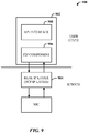
- FIG. 9 illustrates an alternative implementation 900 via a user-level intermediate layer 902.
- the user-level intermediate layer 902 is introduced above the TCP/IP layer 904.
- the intermediate layer 902 maintains P2P connections with other nodes in the P2P network using a P2P component 906, and provides an API 908 to applications for interfacing to the P2P network.
- This API 908 can be similar to standard socket APIs which will allow programmers to develop applications utilizing the power of an IVLAN layer based on knowledge of network socket communications.
- FIG. 10 illustrates an alternative implementation 1000 that employs a kernel-level intermediate layer 1002.
- the kernel-level intermediate layer 1002 is introduced between the TCP/IP layer 904 and NIC driver 1004.
- the role of the intermediate layer is to bridge packets destined to the virtual IP layer, to the P2P network.
- FIG. 10 shows one approach where the intermediate layer 1002 can include a built-in P2P component 1006 responsible for communication with the P2P network. While efficient, this solution can be difficult to manage since the support for the P2P network should be integrated in a kernel module.
- FIG. 11 illustrates an alternative approach 1100 where a kernel-level intermediate layer 1102 transfers all the IP packets received from TCP/IP layer 904 for the virtual IP network to a user-level application (e.g., the P2P component) 1104 which in turn uses the P2P APIs to transfer packets to the destination node in the P2P network. The rest of the packets not destined to virtual IP network are passed to the physical NIC.
- this layer can be implemented as an NDIS intermediate driver 1106.
- Another alternative approach employs a kernel-level virtual NIC interface driver.
- the kernel-level virtual NIC driver is introduced that appears to the TCP/IP layer as just another NIC.
- this approach is similar to the kernel-level intermediate layer approach.
- the TCP/IP stack takes care of routing the packets to the right NIC so the driver does not need to determine if packets are destined to the VNIC.
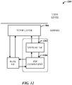
- FIG. 12 illustrates an alternative approach 1200 that employs a kernel-level virtual NIC interface driver 1202 having a built-in P2P component 1204.
- the P2P component 1204 is responsible for communications with the P2P network.
- This solution has the same disadvantage as the kernel-level intermediate layer using a built-in P2P component 1006 of FIG. 10 .
- the Microsoft P2P SDK is a set of networking APIs that enable application programmers to create P2P-based applications.
- the SDK is part of a bigger P2P networking platform which is a developer platform to create P2P applications.
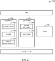
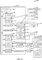
- FIG. 13 illustrates one exemplary system 1300 for components for P2P networking architecture.
- the system 1300 includes a PNRP component 1302 that provides P2P name resolution.
- PNRP is a secure, serverless, scalable and dynamic name registration and name resolution protocol that uses architecture similar to a DHT (distributed hash table) system which resolves a peer name to an IPv6 address.
- a peer name is an endpoint for communication, which can be a computer, a user, a group, a service, etc.
- the peer name can be hashed to a 128-bit peer identifier and a DHT-like algorithm is used to retrieve the location of the host publishing that identifier.
- PNRP does not use a routing table, but rather a cache of PNRP entries.
- a cache maintenance algorithm ensures that each node maintains adequate knowledge of the cloud or a group of other nodes to resolve a peer name.
- the system 1300 can also include a graphing component 1304 responsible for maintaining a mesh or graph of connected peers and, provides flooding and replication of data across the graph.
- the graph is an overlay over IP of nodes connected such that any node may communicate with all other nodes through a series of logical neighbor connections.
- a neighbor in a graph is a node that is one graph hop away (directly connected via a TCP connection).
- a well-connected graph has a path between any two nodes.
- a graph has a "small diameter", that is, a relatively small number of hops between the nodes in the farthest edges of the graph.
- the graph is robust and remains connected even if some nodes or some connections disappear.
- of the graphing component 1304 uses a flood and synchronization subcomponent 1306, a database (or store) subcomponent 1308, and a graph maintenance subcomponent 1310.
- the peer graph uses flooding to publish a data (or name) record in the graph.
- a record name is computed by appending a dot and the graph name to the host name.
- a node publishes (or adds) a new record in the graph then this record is propagated to all the nodes via flooding. If a node makes any changes in an already published record (e.g., updates the record) then these updates are also propagated to all the nodes through flooding. If a node deletes a record then flooding also propagates this deletion to all the nodes in the graph.
- Each record published in the graph is uniquely identified by a globally unique identifier (GUID). Each record also has a version number and an age or status.
- GUID globally unique identifier
- Each record also has a version number and an age or status.
- a synchronization process also ensures that peers have the same set of records.
- the graph maintenance subcomponent 1310 includes an algorithm that defines how the graph evolves, to maintain robust connectivity and to maintain a small diameter.
- the graph maintenance component 1310 achieves this by computing a signature of the graph and using the signature to detect partitions. If a graph is partitioned, each of the partitions will have a different signature.
- the graph maintenance subcomponent 1310 also allows a node to establish appropriate connections when the node enters the graph and leaves the graph without creating a "hole”.
- graph node When records are published in the graph, a graph node that has multiple connections will receive multiple copies of the record. In order to decide which connections to keep and which to remove, graph node evaluates flooded records and calculates a bidirectional utility index of its connections.
- a utility index is a number that indicates the usefulness of the connection in transferring the published record. If a record is received from a connection that has already been previously received from some other connection then the utility index of the connection is decreased. Otherwise, if a new record is received through a connection then the utility index of that connection is increased.
- the graph maintenance algorithm attempts to remove useless connections and establish new connections based on the utility indices of all of the connections a node has and the information that is received during the flooding. In this way, the algorithm tries to converge a graph to a topology that is optimal for flooding for the current traffic pattern.
- a joining node In order to connect to the graph, a joining node connects to a node that is already connected to the graph.
- the joining node resolves the IPv6 address of the contact node in order to connect. This can be done through DNS, peer discovery and name resolution methods such as PNRP, for example, or any other customized method. If the selected contact node has less than a maximum allowable number of graph connections to neighbors, the node will send an accept response. Otherwise, the node will send a rejection response along with a referral list, which is a list of other nodes in the graph.
- the joining node that receives rejection response picks a random node in the referral list and tries to connect to it.
- the node When a node disconnects from a graph, the node sends a disconnect message to the neighbor nodes (the adjacent nodes).
- the disconnect message carries a referral list, which includes neighbors, except the neighbor being disconnected from.
- the other node receives a disconnect message, it tries to connect to a peer in the referral list. This helps in repairing any partition caused by disconnection of the node.
- partitions in the graph may occur.
- Each graph has a graph signature and a number of contact nodes.
- the number of contact nodes is proportional to the size of the graph.
- the contact and graph signature information is refreshed periodically. If the contact and graph signature information becomes stale, a partition has occurred. When a partition is detected, an attempt to communicate with the contact node is made in order to reconnect the graph.
- Graphs are the association of a set of nodes with connections that define a topology for flooding information.
- a graph by itself is unsecured.
- Security of the graph can be provided by pluggable modules in a group component 1312.
- Grouping is the combination of the PNRP component 1302, peer graphing (via the graphing component 1304) and a group security (via a security subcomponent 1314 and a group SSP (security support provider) 1316).
- Grouping provides management of credentials of the members of the group and the secure publication of records in the group.
- the group security subcomponent 1314 uses a peer name to identify each member of the group and to identify each group.
- a group When a group is created, a new public/private key pair for the group is created, upon which a group name is based.
- the member that owns the private key corresponding to the peer name of the group is the group owner. Participation is restricted to a set of peers known as group members. Each group member requires security credentials to prove membership of a group. Once a peer becomes part of a group, the group members use graphing to establish multiple neighbor connections and optimize the shape of the graph for flooding.
- Each peer has an associated peer database (or store 1308) which stores the set of records associated with a graph that are securely published and synchronized between all the members of the group. Graphing ensures that published records are propagated to all the nodes while grouping prevents unauthorized records from being propagated throughout the graph.
- the record replication between members uses SSL (secure socket layer) to provide encryption and data integrity for record data.
- the new peer When a new peer joins the group, the new peer automatically receives all the published records from the current group member to which it attaches. After the initial synchronization, group members periodically resynchronize the published records to ensure that all the group members consistently have the same view of published data.
- a peer uses a local search mechanism to search for a published record. In a local search, the group member only searches its local peer database for the record and does not send search queries to other group members.
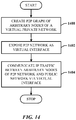
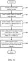
- FIG. 14 illustrates a method of networking devices.
- a P2P graph of arbitrary nodes of a virtual private network is created.
- the P2P network is exposed as a virtual interface.
- IP traffic is communicated between the arbitrary nodes of the P2P network and a public network via the virtual interface.
- FIG. 15 illustrates a method of implementing a private virtual LAN.
- a device operating system is received.
- IVLAN functionality is encapsulated as a mini-port driver (e.g., NDIS) and user-mode process as part of the operating system.
- the IVLAN is exposed via the mini-port driver and user-mode process using an IPv4 and/or IPv6 protocol.
- all packets received are sent to a user-mode overlay manager.
- the manager provides authentication into the IVLAN.
- the manager provides neighbor device discovery and selection.
- the manager provides route management.
- the manager provides packet forwarding to devices of the IVLAN.
- FIG. 16 illustrates a method of receiving and sending IP packets in the IVLAN architecture.
- the IVLAN user application is started.
- the user application enables a VNIC driver interface.
- the user application assigns IPv4 and IPv6 addresses to the virtual interface.
- packets received and intended to the VNIC interface are intercepted by the VNIC driver and forwarded to the user application through the file stream interface.
- packets are encapsulated in P2P messages and routed over the graph to the destination.
- FIG. 17 illustrates a method of receiving and processing IP packets in the IVLAN architecture.
- the destination user application receives packets through neighbor nodes.
- the user application extracts Ethernet packets from the P2P messages and sends the Ethernet packets to the VNIC.
- the VNIC forwards the Ethernet packets into the TCP/IP stack for normal stack processing.
- FIG. 18 illustrates a method of flooding packets in the graph.
- discovery on the graph is initiated.
- packets are received for broadcast and/or multicast.
- the packets are flooded to graph nodes.
- a node forwards received packets to neighbor nodes.
- a node drops redundant packets.
- IVLANs are appropriate for bringing together a collection of Internet (or public network) hosts to facilitate a variety of applications. It can be assumed that IVLAN relationships are generally long-term. Accordingly, at least the following types of IVLANs can be created: a family IVLAN, an extended family IVLAN, and a social network IVLAN.
- IVLANs provide the capability of supporting existing applications and experiences by providing broadcast semantics. Broadcast semantics imply that many existing protocols and applications will run unmodified over the virtual network. For instance, a network explorer can be used to discover resources across all machines within the IVLAN. Other broadcast experiences include discovering meeting, people and media.
- IVLANs provide the capability of transparent "supernode” capabilities by providing forwarding semantics. Because IP routing operates over the IVLAN, connectivity is achieved among all hosts in the IVLAN, even when pairwise connectivity is not available. As a side effect, nodes with good connectivity can seamlessly act as forwarding agents for traffic between other hosts. This capability enables a supernode role that gets created automatically based on the dynamic connectivity of active hosts.
- IVLANs also provide the capability of resilient communications. Dynamic overlay routing can be used to construct resilient networks that "route around" Internet congestion or failures. Moreover, an IVLAN can be employed (e.g., without broadcast semantics) for performing rapid virus signature propagation or software distribution.
- IVLANs include file sharing and access (e.g., particularly media sharing).
- multiple PCs in a "home" can be enabled to share information there between no matter where the computers are located.
- the system can enable remote discovery and access to media sources (e.g., Media Center, media libraries, etc.). Live streaming (and even multi-party streaming) can be enabled.
- IVLANs provide seamless discovery of devices and other resources located in the "home”. IVLANs facilitate home network management and troubleshooting by linking PCs that form a consumer management domain for easy remote network management. IVLANs promote remote access, including remote assistance and meetings. Additionally, content publication to friends and family by way of the creation of personal websites, for example, provides automatic and secure sharing to friends and family within the IVLAN.
- IVLANs can be exposed to users at the application level.
- users may perceive the IVLAN as "private networks” or "network circles.” Therefore, applications may expose functionality in terms of these network circles.
- a photo publishing application Rather than asking the user to enumerate the individual users who may access the photos, the application may provide the option to "publish to your Family network circle.” This automatically exposes the photos for access only through the corresponding IVLAN.
- IVLAN Application awareness of an IVLAN can be employed. If the application knows that it is using an IVLAN, the application can be configured to "see" actual neighbor links, thereby enabling higher-level systems such as DHTs to optimize for that topology.
- multiple simultaneous IVLANs can be employed such that a client can join multiple IVLANs simultaneously.
- each active IVLAN creates a new interface with a private address range. Note that the machine can join the same IVLAN multiple times, once on behalf of each logged-in user.
- IVLANs support bridging to external networks, and thus, the discovery and communication among active nodes. In one respect, however, this design can be limiting, as each node is sitting on a network that contains devices, PCs, and services that may not be active within the IVLAN. Ideally, each node can advertise a route to its local network. In more robust implementations, resources (e.g., devices) outside the IVLAN and thus, do not reside within the broadcast domain of the IVLAN, can be configured to include application features such as network discovery. This can employ a proxy model that enables authorized devices to obtain an identity within the IVLAN.
- One authentication scheme would be that associated with P2P grouping. This scheme essentially creates a private Certificate Authority (CA) and issues membership certificates to all authorized parties. This approach has an advantage that hosts can trust each other by simply verifying that the certificates share a common root. To address certificate revocation, a notion of password-based groups can be employed whereby a node uses a password to access the group and obtains a persistent membership certificate from an administrative node.
- CA Certificate Authority
- end-to-end TCP is likely to have low-to-moderate bandwidth, variable latency, and moderate-to-low reliability.
- TCP congestion control can work effectively in this environment; however, other optimizations are possible.
- IP header compression can be introduced in the IVLAN environment to address the multiple layers of encapsulation (e.g., application->TCP->IP->IPSec).
- Some of the alternative implementations described above seek to remove some of the IP layers entirely, but this optimization could come at the expense of more code (and complexity).
- Another optimization can be to eliminate the overlay tunnel by simply replacing it with point-to-point IPSec.
- IVLAN point-to-point links can use IPSec, then much of the tunnel overhead can be eliminated (there is no need for TLS and TCP encapsulation). However, for this to occur, IPSec should support user-to-user IPSec, as the IVLAN is using per-user credentials.
- Each node will experience traffic that is passed-through and traffic that is destined locally.
- the system can be configured to determine how much bandwidth to dedicate toward traffic forwarding. Additionally, the system can prioritize which traffic to forward, either based on end-to-end application needs or based on fairness policy, for example.
- each node's private IPv6 address resides within a shared subnet, so hierarchical routing schemes such as BGP (border gateway routing) may be inappropriate.
- BGP border gateway routing
- one approach involves each node publishing a list of its neighbors into a database that is replicated over the overlay network. Each node then uses this data to construct its own routing table (based on shortest hop paths).
- Virtual ring routing (VRR) can be another solution.
- DTT distributed routing table
- all protocols normally used for mobile ad-hoc networks can apply, for example, AODV, a proactive protocol (DSDV) and a DHT-based protocol (e.g., VRR).
- the P2P overlay network can seek multiple active connections. Stability of the connections can be considered as well as balancing the potential for route optimization over the cost of route maintenance.
- a "dialer” client can be provided that allows users to manually connect to the desired IVLANs.
- a logical extension to this is support for dial-on-demand.
- a configured IVLAN could reside dormant, exposing a private IPv6 address. When that IPv6 address is actually used, the interface becomes active and connects.
- IVLANs In the context of compartmentalization and security, it would be natural to consider IVLANs as machine-wide constructs. Alternatively, an IVLAN can be scoped for use by individual users (network compartments) or even to specific applications (network views).
- a firewall can be used to prevent packet forwarding (thus making a node into an end-station only).
- Restrictions can also be put into place in enterprises based on the use of IVLANs for domain-joined machines. Moreover, restrictions can be enforced to ensure that IVLANs cannot be used to bridge traffic to the local physical network.
- IVLAN support can provided be available on server SKUs, such that a server can serve as a central node for the home.
- Configured IVLANs can be archived in the network cloud, thereby enabling users to download and configure IVLANs from any Internet host.
- the IVLAN can partially rest on top of a wireless mesh network.
- the wireless mesh network can rely on homogeneous or heterogeneous wireless technologies.
- the IVLAN simply re-uses wireless mesh links to reduce duplicate traffic and enhance performance.
- a machine can automatically validate the health of a peer machine within the IVLAN before accepting connections or traffic from that host. With hosts potentially forwarding traffic on behalf of other hosts, IVLANs should not be used for propagation of worms, viruses, or malware. In view thereof, a lightweight health validation process can be employed in a peer-to-peer fashion. If unhealthy peers are detected, a service may be invoked to support remediation.
- next generation of user experience should include easily managed, ubiquitous access to content and information on any device, anywhere, anytime. Users demand a union of pervasive and collaborative computing and the content. Following is a general description of the types of scenarios that can be offered by the IVLAN architecture.
- a user has multiple PCs at home, and would like to be able to share information between home network PCs and devices. This can be done with an add-on application.
- the user downloads the new add-on and installs it. After installation, the add-on presents a setup or join page that allows configuration of the new network.
- the user is able to choose a name for the home network and a password.
- the user who installed the pack the user can be added as an administrator for the new network.
- the user is taken to a network console that provides instructions on how to add more PCs to the new network.
- the instructions can include name and password, setting up another PC, (optionally, provisioning a USB key and using the key on another PC), and via a strong password which allows the user to download or transport the add-on.
- the user follows the instructions which indicate to go to another PC and join it to the new network.
- the PC is joined to the network.
- the network is already listed, and the user can simply enter the password for the network.
- the network console is presented which allows for auto-publication of the network to other devices, and easy joining via a password.
- the user sees that the other PC is listed, and is presented with vital security information and the current operating system update status.
- the user can also be presented with all accounts on both PCs and that the PCs have already been added to a people section. The user can then review the accounts and status on the other PCs. Finally, the user also sees the list of devices attached to the PCs and the network.
- the devices attached to the PCs have already been added to the network.
- Network devices are presented for confirmation.
- the console can be lightweight for home network management, has the ability to manage users, the ability to view/manage PC updates, and the ability to view/manage devices associated with the home network.
- the IVLAN architecture facilitates accessing a single desktop from anywhere.
- the user can see, via the second PC that the account is already setup, and is able to login to the new PC.
- the new PC desktop can have the same theme as the same elements as the other PC did (e.g., same desktop background, etc.).
- Documents on the new PC and the first PC can be browsed in a document area that presents one aggregated view of all the documents.
- a photo section can present all the photos accessible by the network.
- a media player application can have already catalogued the music accessible on the network.
- Printer and printing settings can also be replicated for the new PC. In other words, desktop settings are replicated, user accounts are replicated to other PCs, documents, photos, music, etc., are all made available in normal places, and devices are setup for use.
- Network connectivity is also made available over the Internet, and all devices and content in network are made available to a user device over the Internet. For example, from the Internet, the user can access a PC on the home network and print a document to the home printer.
- the user can create a website on the home network that can be made accessible to users through the IVLAN. Photos and other types of documents and media can be added for viewing or downloading. Content can be added to the website dragging and dropping audio, photo, and/or media files into the experience.
- the user can also choose to publish a calendar, for example. The website can be published to selected individuals, directly from a network PC, and announce to the selected contacts.
- site access is granted and content viewed.
- the contact can subscribe to and view the user's calendar.
- the contact can also subscribe to any updates the user makes to the web site and to photo or the media updates. Commenting can also be provided for the contact to comment and/or annotate user content.
- the capabilities include at least receiving announcements (e.g., email or toast), accessing the site and viewing the content, subscribing to different "feeds" of content, and commenting on the content.
- notifications of newly posted content can be provided locally over the IVLAN, and notifications of newly changed subscription feeds provided locally.
- content can be uploaded to the private website as if the user was on another PC of the home network.
- the publication site Based on being logged into the home network, the publication site recognizes the new content and prompts the user whether the content should be posted. The user confirms and the content is posted. The contact recipient is notified of the new content and the user is able to set up a rule that all pictures from this camera should be published to the site.
- capability is provided to upload content from remote locations, add content to the site remotely, home network integration, and upload pictures from the camera automatically to a home network PC from anywhere.
- Identities provide means to "know” and “be known”, and enable end-to-end secure, reliable, connectivity. Identities can be divided into two categories: personal and contacts.
- the personal identity is the logical set of information that describes who "I am" to the network and to others.
- the personal identity contains metadata, such as nickname or home address, and credentials used to prove who identity to other people and contacts.
- Contacts are the personal identities of other people a person "knows' or “trusts”. Contacts are used to authenticate, authorize, and manage metadata about another individual. It is desirable for individuals in a personal contact list to be explicitly trusted locally or verified via a trusted third party.
- the association of individuals or PCs together utilizes a group semantic. This group is able to communicate and authenticate each other into the group. Once in the group, communications happens securely without being prone to an attacking outsider. Each member of the group trusts the other members, and data can be passed between the group members based on a member permissions associated with an access control list (ACL), if desired.
- ACL access control list
- Seamless communication between nodes in the local or distributed network is desirable for enabling the experiences.
- End-to-end secure, reliable, connectivity should be provided to enable the experiences.
- IP addresses are dynamic, a mechanism can be employed to identify endpoints without fear of those identifiers changing. These identifiers map to an identity (or which can be the identity), so resolution from an identity to an endpoint can occur.
- This technology could be a rendezvous server that authenticates identities and returns the endpoint associated with a registered identity. Since it can be anticipated that billions of users could be utilizing the IVLAN architecture, a peer-to-peer solution that provides fixed identifiers secured by an identity and resolvable without a server can be alternative solution.
- PNRP is a solution that fulfills most of these requirements.
- edge security is needed to protect users. Users must know that they are indeed communicating with the correct contact, that the communication is secured, and that the person they are communicating with is only receiving information they are authorized to receive.
- IPSec One solution to this firewall concern is IPSec.
- Network device discovery provides users the ability to discover and associate with devices on the network. Once associated with a machine, the device can be used as if it was attached to the PC directly. Once the device is associated with the PC, users can then manage the devices associated with the system, or take advantage of installed features (e.g., printer options) to utilize the device more effectively.
- a next generation of device is one that can be communicated with over the Internet and that communicates across the Internet (e.g., and Internet camera).
- users could take a picture in Hawaii, and have it automatically sent back to a PC at home using the disclosed IVLAN architecture.
- a WS-Devices protocol and other technology suites can enable this scenario.
- the home network group can be published in a Global PNRP cloud as an endpoint that can be resolved to any node in the home network. Once resolved, a connection can be established over IPv6 utilizing the NAT and firewall traversal solutions to ensure connectivity. Once the connection is established, the content/state synchronization utilization can occur. This can also include a mechanism that invokes a device action remotely. This can be in the form of a proxy execution from the group association, for example.
- a component can be, but is not limited to being, a process running on a processor, a processor, a hard disk drive, multiple storage drives (of optical and/or magnetic storage medium), an object, an executable, a thread of execution, a program, and/or a computer.
- a component can be, but is not limited to being, a process running on a processor, a processor, a hard disk drive, multiple storage drives (of optical and/or magnetic storage medium), an object, an executable, a thread of execution, a program, and/or a computer.
- an application running on a server and the server can be a component.
- One or more components can reside within a process and/or thread of execution, and a component can be localized on one computer and/or distributed between two or more computers.
- FIG. 19 there is illustrated a block diagram of a computing system 1900 operable to execute the disclosed IVLAN architecture.
- FIG. 19 and the following discussion are intended to provide a brief, general description of a suitable computing system 1900 in which the various aspects can be implemented. While the description above is in the general context of computer-executable instructions that may run on one or more computers, those skilled in the art will recognize that a novel embodiment also can be implemented in combination with other program modules and/or as a combination of hardware and software.
- program modules include routines, programs, components, data structures, etc., that perform particular tasks or implement particular abstract data types.
- inventive methods can be practiced with other computer system configurations, including single-processor or multiprocessor computer systems, minicomputers, mainframe computers, as well as personal computers, hand-held computing devices, microprocessor-based or programmable consumer electronics, and the like, each of which can be operatively coupled to one or more associated devices.
- the illustrated aspects can also be practiced in distributed computing environments where certain tasks are performed by remote processing devices that are linked through a communications network.
- program modules can be located in both local and remote memory storage devices.
- Computer-readable media can be any available media that can be accessed by the computer and includes volatile and non-volatile media, removable and non-removable media.
- Computer-readable media can comprise computer storage media and communication media.
- Computer storage media includes volatile and non-volatile, removable and non-removable media implemented in any method or technology for storage of information such as computer-readable instructions, data structures, program modules or other data.
- Computer storage media includes, but is not limited to, RAM, ROM, EEPROM, flash memory or other memory technology, CD-ROM, digital video disk (DVD) or other optical disk storage, magnetic cassettes, magnetic tape, magnetic disk storage or other magnetic storage devices, or any other medium which can be used to store the desired information and which can be accessed by the computer.
- the exemplary computing system 1900 for implementing various aspects includes a computer 1902, the computer 1902 including a processing unit 1904, a system memory 1906 and a system bus 1908.
- the system bus 1908 provides an interface for system components including, but not limited to, the system memory 1906 to the processing unit 1904.
- the processing unit 1904 can be any of various commercially available processors. Dual microprocessors and other multi-processor architectures may also be employed as the processing unit 1904.
- the system bus 1908 can be any of several types of bus structure that may further interconnect to a memory bus (with or without a memory controller), a peripheral bus, and a local bus using any of a variety of commercially available bus architectures.
- the system memory 1906 includes read-only memory (ROM) 1910 and random access memory (RAM) 1912.
- ROM read-only memory
- RAM random access memory
- a basic input/output system (BIOS) is stored in a non-volatile memory 1910 such as ROM, EPROM, EEPROM, which BIOS contains the basic routines that help to transfer information between elements within the computer 1902, such as during start-up.
- the RAM 1912 can also include a high-speed RAM such as static RAM for caching data.
- the computer 1902 further includes an internal hard disk drive (HDD) 1914 (e.g., EIDE, SATA), which internal hard disk drive 1914 may also be configured for external use in a suitable chassis (not shown), a magnetic floppy disk drive (FDD) 1916, (e.g., to read from or write to a removable diskette 1918) and an optical disk drive 1920, (e.g., reading a CD-ROM disk 1922 or, to read from or write to other high capacity optical media such as the DVD).
- the hard disk drive 1914, magnetic disk drive 1916 and optical disk drive 1920 can be connected to the system bus 1908 by a hard disk drive interface 1924, a magnetic disk drive interface 1926 and an optical drive interface 1928, respectively.
- the interface 1924 for external drive implementations includes at least one or both of Universal Serial Bus (USB) and IEEE 1394 interface technologies.
- the drives and their associated computer-readable media provide nonvolatile storage of data, data structures, computer-executable instructions, and so forth.
- the drives and media accommodate the storage of any data in a suitable digital format.
- computer-readable media refers to a HDD, a removable magnetic diskette, and a removable optical media such as a CD or DVD, it should be appreciated by those skilled in the art that other types of media which are readable by a computer, such as zip drives, magnetic cassettes, flash memory cards, cartridges, and the like, may also be used in the exemplary operating environment, and further, that any such media may contain computer-executable instructions for performing novel methods of the disclosed architecture.
- a number of program modules can be stored in the drives and RAM 1912, including an operating system 1930, one or more application programs 1932, other program modules 1934 and program data 1936.
- the one or more application programs 1932, other program modules 1934 and program data 1936 can include the management component 102, client 104, interface component 114, the virtual IP layer 202, P2P layer 204, real IP layer 206, the user application 304, VNIC 302 and subcomponents (306, 308, 310), the TCP/IP layer 312, the legacy applications (APP1, APP2), the local DNS resolver 702 and NL 704, overlay manager 802, credential store 804, setup and monitoring component 806, PNRP 808, and the components of systems 900, 100, 1100, 1200 and 1300, for example.
- All or portions of the operating system, applications, modules, and/or data can also be cached in the RAM 1912. It is to be appreciated that the disclosed architecture can be implemented with various commercially available operating systems or combinations of operating systems.
- a user can enter commands and information into the computer 1902 through one or more wire/wireless input devices, for example, a keyboard 1938 and a pointing device, such as a mouse 1940.
- Other input devices may include a microphone, an IR remote control, a joystick, a game pad, a stylus pen, touch screen, or the like.
- These and other input devices are often connected to the processing unit 1904 through an input device interface 1942 that is coupled to the system bus 1908, but can be connected by other interfaces, such as a parallel port, an IEEE 1394 serial port, a game port, a USB port, an IR interface, etc.
- a monitor 1944 or other type of display device is also connected to the system bus 1908 via an interface, such as a video adapter 1946.
- a computer typically includes other peripheral output devices (not shown), such as speakers, printers, etc.
- the computer 1902 may operate in a networked environment using logical connections via wire and/or wireless communications to one or more remote computers, such as a remote computer(s) 1948.
- the remote computer(s) 1948 can be a workstation, a server computer, a router, a personal computer, portable computer, microprocessor-based entertainment appliance, a peer device or other common network node, and typically includes many or all of the elements described relative to the computer 1902, although, for purposes of brevity, only a memory/storage device 1950 is illustrated.
- the logical connections depicted include wire/wireless connectivity to a local area network (LAN) 1952 and/or larger networks, for example, a wide area network (WAN) 1954 and/or the IVLAN described herein.
- LAN and WAN networking environments are commonplace in offices and companies, and facilitate enterprise-wide computer networks, such as intranets, all of which may connect to a global communications network, for example, the Internet.
- the computer 1902 When used in a LAN networking environment, the computer 1902 is connected to the local network 1952 through a wire and/or wireless communication network interface or adapter 1956.
- the adaptor 1956 may facilitate wire or wireless communication to the LAN 1952, which may also include a wireless access point disposed thereon for communicating with the wireless adaptor 1956.
- the computer 1902 can include a modem 1958, or is connected to a communications server on the WAN 1954, or has other means for establishing communications over the WAN 1954, such as by way of the Internet.
- the modem 1958 which can be internal or external and a wire and/or wireless device, is connected to the system bus 1908 via the serial port interface 1942.
- program modules depicted relative to the computer 1902, or portions thereof, can be stored in the remote memory/storage device 1950. It will be appreciated that the network connections shown are exemplary and other means of establishing a communications link between the computers can be used.
- the computer 1902 is operable to communicate with any wireless devices or entities operatively disposed in wireless communication, for example, a printer, scanner, desktop and/or portable computer, portable data assistant, communications satellite, any piece of equipment or location associated with a wirelessly detectable tag (e.g., a kiosk, news stand, restroom), and telephone.
- any wireless devices or entities operatively disposed in wireless communication for example, a printer, scanner, desktop and/or portable computer, portable data assistant, communications satellite, any piece of equipment or location associated with a wirelessly detectable tag (e.g., a kiosk, news stand, restroom), and telephone.
- the communication can be a predefined structure as with a conventional network or simply an ad hoc communication between at least two devices.
- Wi-Fi Wireless Fidelity
- Wi-Fi is a wireless technology similar to that used in a cell phone that enables such devices, for example, computers, to send and receive data indoors and out; anywhere within the range of a base station.
- Wi-Fi networks use radio technologies called IEEE 802.11x (e.g., a, b, g, etc.) to provide secure, reliable, fast wireless connectivity.
- IEEE 802.11x e.g., a, b, g, etc.
- a Wi-Fi network can be used to connect computers to each other, to the Internet, and to wire networks (which use IEEE 802.3 or Ethernet).
Landscapes
- Engineering & Computer Science (AREA)
- Computer Networks & Wireless Communication (AREA)
- Signal Processing (AREA)
- Computer Security & Cryptography (AREA)
- Computing Systems (AREA)
- Data Exchanges In Wide-Area Networks (AREA)
Claims (12)
- Client (104) für ein computerimplementiertes Netzwerksystem, wobei der Client aufweist:eine Verwaltungskomponente (102) zur Erzeugung und Verwaltung eines Gerät-zu-Gerät, P2P-, Graphen (106), der einem privaten virtuellen Netzwerk (108) für P2P-Kommunikationen zwischen arbiträren Knoten (110, 112) überlagert ist;eine Schnittstellenkomponente (114) zum Zugänglichmachen der arbiträren Knoten des P2P-Graphen für einen öffentlichen Knoten (116), wobei die Schnittstellenkomponente aufweisteine virtuelle Netzwerkschnittstellenkarte, VNIC (302); undeine Dateistromschnittstelle zum Durchleiten von IP-Paketen zwischen der VNIC und der Verwaltungskomponente zum Weiterleiten und zum Senden an die arbiträren Knoten des P2P-Graphen,wobei der Client ferner eine Auflösungseinheit für lokale Namen (702) zum Auflösen von Namensaufzeichnungen in dem Graphen aufweist, von denen der öffentliche Knoten eine Knoteninformation der arbiträren Knoten über ein Geräteauffindungs-Serverloses-Namens-Auflösungsprotokoll erhält, wobei die Auflösungseinheit für lokale Namen ausgebildet ist, eine Liste (704) aus Gerätekennungen, IP-Adressen und Namensaufzeichnungen, die durch alle Geräte veröffentlicht sind, zu bewahren und alle DNS-Anforderungen lokal abzuarbeiten, undwobei der Client ferner ausgebildet ist, Namensaufzeichnungen in dem Graphen öffentlich zu machen und die Namensaufzeichnung an die arbiträren Knoten des virtuellen privaten Netzwerks auszugeben.
- Client nach Anspruch 1, wobei die Schnittstellenkomponente den P2P-Graphen für den öffentlichen Knoten als eine virtuelle Schnittstelle (202) zugänglich macht.
- Client nach Anspruch 1, wobei die Verwaltungskomponente auf einer physischen Schnittstellen (206)-IP-Adresse erzeugt wird.
- Client nach Anspruch 3, wobei die IP-Adresse eine IPv4-Adresse oder eine IPv6-Adresse ist.
- Client nach Anspruch 1, wobei die VNIC (302) durch einen VNIC-Treiber (306) gesteuert ist, wobei der VNIC-Treiber einen Miniport-Treiber (308) und eine Dateistromschnittstelle (310) zugänglich macht.
- Client nach Anspruch 5, wobei die Verwaltungskomponente aufweist:
eine Anwendung auf Benutzerebene (304) zur Steuerung und Konfigurierung des VNIC-Treibers und zur Übermittlung von IP-Paketen anstelle der VNIC; und/oder ein Weiterleitungsprotokoll zur Ermöglichung einer Mehrfachsprungnachrichtenweiterleitung über den P2P-Graphen. - Client nach Anspruch 1, wobei die Verwaltungskomponente Multicastdatenverkehr und/oder Rundrufdatenverkehr und/oder
ein Durchlaufen eines Firewallsystems und/oder eines Netzwerkadressenübersetzungssystems ermöglicht. - Computerimplementiertes Verfahren für einen Client (104) eines computerimplementierten Netzwerksystems, mit:Erzeugen (1400), durch eine Verwaltungskomponente (102) des Client (104), eines P2P-Graphen (106) aus arbiträren Knoten (110, 112), der einem virtuellen privaten Netzwerk (108) überlagert ist;Zugänglichmachen (1402) des P2P-Graphen als eine virtuelle Schnittstelle mittels einer Schnittstellenkomponente (114) des Client (104), die eine virtuelle Netzwerkschnittstellenkarte, VNIC (302), aufweist; undÜbermitteln (1404), durch eine Dateistromschnittstelle der Schnittstellenkomponente (114), von IP-Datenverkehr zwischen arbiträren Knoten des P2P-Graphen und einem öffentlichen Netzwerk mittels des virtuellen Netzwerks,Bereitstellen, durch eine Auflösungseinheit für lokale Namen (702) des Client (104) für einen Knoten des öffentlichen Netzwerkknotens, von Information über einen der arbiträren Knoten durch ein Geräte-Auffindungs-Serverloses-Namensauflösungs-Protokoll, das das Unterhalten einer Liste (704) von Gerätekennungen, IP-Adressen und Namensaufzeichnungen, die durch alle Geräte öffentlich gemacht sind, und das Auflösen aller DNS-Anforderungen lokal durch die Auflösungseinheit für lokale Namen (702) beinhaltet,wobei das Verfahren ferner umfasst:
Veröffentlichen der Clientnamenaufzeichnungen in dem Graphen und Ausgeben der Namensaufzeichnungen an die arbiträren Knoten des virtuellen privaten Netzwerks. - Verfahren nach Anspruch 8, das ferner umfasst: Zuweisen einer privaten IP-Adresse zu jedem der arbiträren Knoten.
- Verfahren nach Anspruch 8, das ferner umfasst: Ermöglichen einer Mehrfachsprungnachrichtenweiterleitung einer Nachricht über den P2P-Graphen und/oder Bereitstellen von Punkt-zu-Punkt-TCP-Verbindungen für direkte Kommunikation zwischen teilnehmenden Knoten des Graphen.
- Verfahren nach Anspruch 8, das ferner umfasst: Zugänglichmachen von IPv4 und IPv6-Schnittstellen zur Verwendung in entsprechenden Anwendungen.
- Verfahren nach Anspruch 8, das ferner umfasst: Replizieren einer Datenbank aus den arbiträren Knoten.
Applications Claiming Priority (3)
| Application Number | Priority Date | Filing Date | Title |
|---|---|---|---|
| US89851907P | 2007-01-30 | 2007-01-30 | |
| US11/769,941 US8489701B2 (en) | 2007-01-30 | 2007-06-28 | Private virtual LAN spanning a public network for connection of arbitrary hosts |
| PCT/US2008/051046 WO2008094751A1 (en) | 2007-01-30 | 2008-01-15 | Private virtual lan spanning a public network for connection of arbitrary hosts |
Publications (3)
| Publication Number | Publication Date |
|---|---|
| EP2127224A1 EP2127224A1 (de) | 2009-12-02 |
| EP2127224A4 EP2127224A4 (de) | 2015-07-01 |
| EP2127224B1 true EP2127224B1 (de) | 2019-12-18 |
Family
ID=39669193
Family Applications (1)
| Application Number | Title | Priority Date | Filing Date |
|---|---|---|---|
| EP08705920.0A Active EP2127224B1 (de) | 2007-01-30 | 2008-01-15 | Privates virtuelles lan zum spanning eines öffentlichen netzwerks zwecks verbindung arbiträrer hosts |
Country Status (4)
| Country | Link |
|---|---|
| US (1) | US8489701B2 (de) |
| EP (1) | EP2127224B1 (de) |
| CN (1) | CN101595688B (de) |
| WO (1) | WO2008094751A1 (de) |
Families Citing this family (128)
| Publication number | Priority date | Publication date | Assignee | Title |
|---|---|---|---|---|
| US8924524B2 (en) * | 2009-07-27 | 2014-12-30 | Vmware, Inc. | Automated network configuration of virtual machines in a virtual lab data environment |
| US8997206B2 (en) * | 2007-06-06 | 2015-03-31 | Avaya Inc. | Peer-to-peer network over a virtual private network |
| US7962089B1 (en) * | 2007-07-02 | 2011-06-14 | Rockwell Collins, Inc. | Method and system of supporting policy based operations for narrowband tactical radios |
| CN101425958A (zh) * | 2007-10-29 | 2009-05-06 | 华为技术有限公司 | 一种p2p叠加网中请求应答方法、装置和系统 |
| KR100930037B1 (ko) * | 2007-12-17 | 2009-12-07 | 한국전자통신연구원 | 네트워크 주소 변환 시뮬레이션 방법 및 그 시스템 |
| US20090249471A1 (en) * | 2008-03-27 | 2009-10-01 | Moshe Litvin | Reversible firewall policies |
| US8549347B1 (en) | 2010-12-20 | 2013-10-01 | Amazon Technologies, Inc. | Techniques for network replication |
| US8429739B2 (en) * | 2008-03-31 | 2013-04-23 | Amazon Technologies, Inc. | Authorizing communications between computing nodes |
| EP2107715B1 (de) * | 2008-03-31 | 2019-12-25 | Synopsys, Inc. | Verfahren, Vorrichtungsanordnung und Computerprogrammprodukt zur Erzeugung eines Identitätsgraphs zur Kommunikationsnetzwerksanalyse |
| US8254287B2 (en) * | 2008-06-17 | 2012-08-28 | Qualcomm Incorporated | Methods and apparatus for optimal participation of devices in a peer to peer overlay network |
| US10880340B2 (en) | 2008-11-26 | 2020-12-29 | Free Stream Media Corp. | Relevancy improvement through targeting of information based on data gathered from a networked device associated with a security sandbox of a client device |
| US9386356B2 (en) | 2008-11-26 | 2016-07-05 | Free Stream Media Corp. | Targeting with television audience data across multiple screens |
| US9154942B2 (en) | 2008-11-26 | 2015-10-06 | Free Stream Media Corp. | Zero configuration communication between a browser and a networked media device |
| US8180891B1 (en) | 2008-11-26 | 2012-05-15 | Free Stream Media Corp. | Discovery, access control, and communication with networked services from within a security sandbox |
| US10631068B2 (en) | 2008-11-26 | 2020-04-21 | Free Stream Media Corp. | Content exposure attribution based on renderings of related content across multiple devices |
| US9986279B2 (en) | 2008-11-26 | 2018-05-29 | Free Stream Media Corp. | Discovery, access control, and communication with networked services |
| US10977693B2 (en) | 2008-11-26 | 2021-04-13 | Free Stream Media Corp. | Association of content identifier of audio-visual data with additional data through capture infrastructure |
| US9961388B2 (en) | 2008-11-26 | 2018-05-01 | David Harrison | Exposure of public internet protocol addresses in an advertising exchange server to improve relevancy of advertisements |
| US10567823B2 (en) | 2008-11-26 | 2020-02-18 | Free Stream Media Corp. | Relevant advertisement generation based on a user operating a client device communicatively coupled with a networked media device |
| US9519772B2 (en) | 2008-11-26 | 2016-12-13 | Free Stream Media Corp. | Relevancy improvement through targeting of information based on data gathered from a networked device associated with a security sandbox of a client device |
| US10334324B2 (en) | 2008-11-26 | 2019-06-25 | Free Stream Media Corp. | Relevant advertisement generation based on a user operating a client device communicatively coupled with a networked media device |
| US10419541B2 (en) | 2008-11-26 | 2019-09-17 | Free Stream Media Corp. | Remotely control devices over a network without authentication or registration |
| US9026668B2 (en) | 2012-05-26 | 2015-05-05 | Free Stream Media Corp. | Real-time and retargeted advertising on multiple screens of a user watching television |
| US9043463B1 (en) * | 2009-03-30 | 2015-05-26 | Amazon Technologies, Inc. | Providing extendible network capabilities for managed computer networks |
| US8339994B2 (en) * | 2009-08-27 | 2012-12-25 | Brocade Communications Systems, Inc. | Defining an optimal topology for a group of logical switches |
| US20110110377A1 (en) * | 2009-11-06 | 2011-05-12 | Microsoft Corporation | Employing Overlays for Securing Connections Across Networks |
| US9379946B2 (en) | 2009-11-12 | 2016-06-28 | Microsoft Technology Licensing, Llc | Model-based virtual networking |
| US8832281B2 (en) * | 2010-01-08 | 2014-09-09 | Tangome, Inc. | Utilizing resources of a peer-to-peer computer environment |
| US8560633B2 (en) | 2010-01-11 | 2013-10-15 | Tangome, Inc. | Communicating in a peer-to-peer computer environment |
| US9819840B2 (en) | 2010-01-11 | 2017-11-14 | Bryan Nunes | Audio device that extracts the audio of a multimedia stream and serves the audio on a network while the video is displayed |
| US9438360B2 (en) | 2010-01-11 | 2016-09-06 | Signet Media, Inc. | System and method for providing an audio component of a multimedia content displayed on an electronic display device to one or more wireless computing devices |
| US9094527B2 (en) * | 2010-01-11 | 2015-07-28 | Tangome, Inc. | Seamlessly transferring a communication |
| US8688994B2 (en) | 2010-06-25 | 2014-04-01 | Microsoft Corporation | Federation among services for supporting virtual-network overlays |
| US9455898B2 (en) | 2010-09-17 | 2016-09-27 | Oracle International Corporation | System and method for facilitating protection against run-away subnet manager instances in a middleware machine environment |
| US10429869B2 (en) | 2011-02-16 | 2019-10-01 | Kortek Industries Pty Ltd | Wireless power, light and automation control |
| AU2011359604B2 (en) * | 2011-02-16 | 2014-05-22 | Kortek Industries Pty Ltd | Wireless power, light and automation control |
| JP2014523557A (ja) | 2011-05-27 | 2014-09-11 | ノキア コーポレイション | ソーシャルネットワークを介して通信設定を共有する方法及び装置 |
| US8713649B2 (en) | 2011-06-03 | 2014-04-29 | Oracle International Corporation | System and method for providing restrictions on the location of peer subnet manager (SM) instances in an infiniband (IB) network |
| US9240981B2 (en) | 2011-06-03 | 2016-01-19 | Oracle International Corporation | System and method for authenticating identity of discovered component in an infiniband (IB) network |
| CN102281180A (zh) * | 2011-07-14 | 2011-12-14 | 冶金自动化研究设计院 | 应用于不同局域网的终端相互通讯的虚拟网卡通讯装置 |
| US8705545B2 (en) * | 2011-08-18 | 2014-04-22 | Oracle International Corporation | N-way routing packets across an intermediate network |
| US20230254292A1 (en) * | 2011-09-09 | 2023-08-10 | Primes Lab Inc. | Private and Secure Chat Connection Mechanism for Use in a Private Communication Architecture |
| US20130110999A1 (en) * | 2011-10-28 | 2013-05-02 | LogMeln, Inc. | Creating an optimized distribution network for the efficient transfer of data between endpoints |
| CN103139540A (zh) * | 2011-11-30 | 2013-06-05 | 北京航天长峰科技工业集团有限公司 | 一种应急现场监控系统 |
| US9350814B2 (en) | 2012-02-21 | 2016-05-24 | Qualcomm Incorporated | Internet protocol connectivity over a service-oriented architecture bus |
| US9621458B2 (en) | 2012-02-21 | 2017-04-11 | Qualcomm Incorporated | Internet routing over a service-oriented architecture bus |
| US9185070B2 (en) * | 2012-05-17 | 2015-11-10 | Harris Corporation | MANET with DNS database resource management and related methods |
| US9262155B2 (en) | 2012-06-04 | 2016-02-16 | Oracle International Corporation | System and method for supporting in-band/side-band firmware upgrade of input/output (I/O) devices in a middleware machine environment |
| US9401963B2 (en) | 2012-06-04 | 2016-07-26 | Oracle International Corporation | System and method for supporting reliable connection (RC) based subnet administrator (SA) access in an engineered system for middleware and application execution |
| KR20130137379A (ko) * | 2012-06-07 | 2013-12-17 | 삼성전자주식회사 | 홈 네트워크에서 사용자 정보를 저장하는 장치 및 방법 |
| US10880162B1 (en) | 2012-07-06 | 2020-12-29 | Cradlepoint, Inc. | Linking logical broadcast domains |
| US10110417B1 (en) * | 2012-07-06 | 2018-10-23 | Cradlepoint, Inc. | Private networks overlaid on cloud infrastructure |
| US10560343B1 (en) | 2012-07-06 | 2020-02-11 | Cradlepoint, Inc. | People centric management of cloud networks via GUI |
| US9992062B1 (en) | 2012-07-06 | 2018-06-05 | Cradlepoint, Inc. | Implicit traffic engineering |
| US10177957B1 (en) | 2012-07-06 | 2019-01-08 | Cradlepoint, Inc. | Connecting a cloud network to the internet |
| US10601653B2 (en) | 2012-07-06 | 2020-03-24 | Cradlepoint, Inc. | Implicit traffic engineering |
| US10135677B1 (en) | 2012-07-06 | 2018-11-20 | Cradlepoint, Inc. | Deployment of network-related features over cloud network |
| US8893262B2 (en) | 2012-08-30 | 2014-11-18 | Tropos Networks, Inc. | Establishing an IPsec (internet protocol security) VPN (virtual private network) tunnel |
| CN102857416B (zh) * | 2012-09-18 | 2016-09-28 | 中兴通讯股份有限公司 | 一种实现虚拟网络的方法、控制器和虚拟网络 |
| US9521130B2 (en) * | 2012-09-25 | 2016-12-13 | Virnetx, Inc. | User authenticated encrypted communication link |
| US8989183B2 (en) | 2012-10-10 | 2015-03-24 | Microsoft Technology Licensing, Llc | Virtual machine multicast/broadcast in virtual network |
| US9596271B2 (en) * | 2012-10-10 | 2017-03-14 | International Business Machines Corporation | Dynamic virtual private network |
| US9485234B1 (en) * | 2012-11-14 | 2016-11-01 | Amazon Technologies, Inc. | Virtualized endpoints in a multi-tenant environment |
| US9148414B1 (en) | 2012-11-14 | 2015-09-29 | Amazon Technologies, Inc. | Credential management in a multi-tenant environment |
| US8438631B1 (en) | 2013-01-24 | 2013-05-07 | Sideband Networks, Inc. | Security enclave device to extend a virtual secure processing environment to a client device |
| EP2944069B1 (de) * | 2013-01-10 | 2019-03-13 | Telefonaktiebolaget LM Ericsson (publ) | Verbindungsmechanismus für energieeffiziente peer-to-peer-netzwerke |
| US9077759B2 (en) | 2013-01-18 | 2015-07-07 | Apple Inc. | Conflict resolution for keychain syncing |
| US9197700B2 (en) | 2013-01-18 | 2015-11-24 | Apple Inc. | Keychain syncing |
| US9408059B2 (en) * | 2013-02-05 | 2016-08-02 | Terranet Ab | Method and apparatus for communicating between mobile devices |
| WO2014150567A1 (en) * | 2013-03-15 | 2014-09-25 | Asguard Networks, Inc. | Industrial network security |
| US9215075B1 (en) | 2013-03-15 | 2015-12-15 | Poltorak Technologies Llc | System and method for secure relayed communications from an implantable medical device |
| TWI532353B (zh) * | 2013-07-26 | 2016-05-01 | 正文科技股份有限公司 | 社群虛擬網路連線建立方法及網路通信系統 |
| US9489419B2 (en) * | 2013-09-18 | 2016-11-08 | 9Lenses, Inc. | System and method for optimizing business performance with automated social discovery |
| US9203826B1 (en) * | 2014-02-26 | 2015-12-01 | Google Inc. | Authentication based on peer attestation |
| CN103812751A (zh) * | 2014-02-28 | 2014-05-21 | 成都卫士通信息产业股份有限公司 | 一种基于ndis的ssl vpn终端数据交互方法 |
| WO2015139026A2 (en) | 2014-03-14 | 2015-09-17 | Go Tenna Inc. | System and method for digital communication between computing devices |
| US9794186B2 (en) | 2014-03-27 | 2017-10-17 | Nicira, Inc. | Distributed network address translation for efficient cloud service access |
| US9825854B2 (en) * | 2014-03-27 | 2017-11-21 | Nicira, Inc. | Host architecture for efficient cloud service access |
| US9794218B2 (en) | 2014-04-29 | 2017-10-17 | Trustiosity, Llc | Persistent network addressing system and method |
| US10148736B1 (en) * | 2014-05-19 | 2018-12-04 | Amazon Technologies, Inc. | Executing parallel jobs with message passing on compute clusters |
| TW201546649A (zh) * | 2014-06-05 | 2015-12-16 | Cavium Inc | 用於基於硬體安全模組的基於雲端的web服務安全管理的系統和方法 |
| US9729580B2 (en) | 2014-07-30 | 2017-08-08 | Tempered Networks, Inc. | Performing actions via devices that establish a secure, private network |
| CN104243632A (zh) * | 2014-10-13 | 2014-12-24 | 三星电子(中国)研发中心 | 使非ip设备接入虚拟ip网络的方法和系统 |
| US10148514B2 (en) * | 2014-12-23 | 2018-12-04 | Intel Corporation | Device discovery using discovery nodes |
| US10021065B2 (en) | 2015-01-27 | 2018-07-10 | Anchorfree Inc. | System and method for suppressing DNS requests |
| US9819513B2 (en) * | 2015-01-27 | 2017-11-14 | Anchorfree Inc. | System and method for suppressing DNS requests |
| US9923865B1 (en) * | 2015-02-18 | 2018-03-20 | Amazon Technologies, Inc. | Network address management |
| AU2016235087A1 (en) * | 2015-03-24 | 2017-09-21 | Kyndi, Inc. | Cognitive memory graph indexing, storage and retrieval |
| CN104954260A (zh) * | 2015-05-22 | 2015-09-30 | 上海斐讯数据通信技术有限公司 | 一种基于数据链路层的点对点vpn路由方法及系统 |
| US9300635B1 (en) | 2015-06-15 | 2016-03-29 | Tempered Networks, Inc. | Overlay network with position independent insertion and tap points |
| CN106330997B (zh) * | 2015-06-19 | 2019-08-09 | 网宿科技股份有限公司 | 一种用于移动终端应用的内容分发的方法和系统 |
| US10476980B2 (en) | 2015-08-07 | 2019-11-12 | Dell Products L.P. | Remote socket splicing system |
| JP6512037B2 (ja) * | 2015-08-31 | 2019-05-15 | 沖電気工業株式会社 | 無線通信装置、方法、及びプログラム |
| TWI595765B (zh) * | 2015-10-22 | 2017-08-11 | 財團法人工業技術研究院 | 穿透網路位置轉換器之方法及通訊裝置 |
| CN105824921A (zh) | 2016-03-16 | 2016-08-03 | 广州彩瞳网络技术有限公司 | 用户社会关系识别装置和方法 |
| TWI625949B (zh) * | 2016-06-06 | 2018-06-01 | Chunghwa Telecom Co Ltd | Control system for controlling virtual overlay network through controller to generate tenant virtual network and control method thereof |
| US9959840B2 (en) | 2016-06-23 | 2018-05-01 | Bryan Nunes | Multimedia servers that broadcast packet-switched audio with second screen content |
| US9854302B1 (en) | 2016-06-23 | 2017-12-26 | Bryan Nunes | Multimedia servers that broadcast a channel listing and packet-switched audio |
| US9729581B1 (en) | 2016-07-01 | 2017-08-08 | Tempered Networks, Inc. | Horizontal switch scalability via load balancing |
| US10574674B2 (en) * | 2016-07-08 | 2020-02-25 | Nec Corporation | Host level detect mechanism for malicious DNS activities |
| JP6771650B2 (ja) * | 2016-08-09 | 2020-10-21 | 華為技術有限公司Huawei Technologies Co.,Ltd. | クラウドコンピューティングシステムにおいて仮想マシンが物理サーバにアクセスするための方法、装置、およびシステム |
| JP6746427B2 (ja) * | 2016-08-10 | 2020-08-26 | キヤノン株式会社 | 通信装置、通信方法、及びプログラム |
| US10257033B2 (en) * | 2017-04-12 | 2019-04-09 | Cisco Technology, Inc. | Virtualized network functions and service chaining in serverless computing infrastructure |
| US10666606B2 (en) * | 2017-06-28 | 2020-05-26 | Amazon Technologies, Inc. | Virtual private network service endpoints |
| CN109561010B (zh) * | 2017-09-26 | 2020-11-20 | 北京金山安全软件有限公司 | 一种报文处理方法、电子设备及可读存储介质 |
| US10944669B1 (en) | 2018-02-09 | 2021-03-09 | GoTenna, Inc. | System and method for efficient network-wide broadcast in a multi-hop wireless network using packet echos |
| US11012418B2 (en) * | 2018-02-15 | 2021-05-18 | Forcepoint Llc | Multi-access interface for internet protocol security |
| US10069726B1 (en) | 2018-03-16 | 2018-09-04 | Tempered Networks, Inc. | Overlay network identity-based relay |
| US11323274B1 (en) | 2018-04-03 | 2022-05-03 | Amazon Technologies, Inc. | Certificate authority |
| US11563590B1 (en) | 2018-04-03 | 2023-01-24 | Amazon Technologies, Inc. | Certificate generation method |
| US11888997B1 (en) * | 2018-04-03 | 2024-01-30 | Amazon Technologies, Inc. | Certificate manager |
| US10116539B1 (en) | 2018-05-23 | 2018-10-30 | Tempered Networks, Inc. | Multi-link network gateway with monitoring and dynamic failover |
| US10158545B1 (en) | 2018-05-31 | 2018-12-18 | Tempered Networks, Inc. | Monitoring overlay networks |
| EP3821587A1 (de) * | 2018-07-11 | 2021-05-19 | Telefonaktiebolaget LM Ericsson (publ) | System und verfahren zur verteilten indexierung in peer-to-peer-netzwerken |
| WO2020023909A1 (en) | 2018-07-27 | 2020-01-30 | GoTenna, Inc. | Vine™: zero-control routing using data packet inspection for wireless mesh networks |
| CN113474733B (zh) * | 2018-12-13 | 2024-08-30 | 新塞尔斯有限公司 | 具有虚拟电网连接的能源虚拟化层 |
| GB201904224D0 (en) * | 2019-03-27 | 2019-05-08 | Sec Dep For Foreign And Commonwealth Affairs | A network filter |
| US11381526B2 (en) | 2019-05-08 | 2022-07-05 | Cisco Technology, Inc. | Multi-tenant optimized serverless placement using smart network interface cards and commodity storage |
| CN111381553B (zh) * | 2020-02-19 | 2022-05-17 | 北京航天智造科技发展有限公司 | 一种基于vpn技术的设备及远程维护plc的方法和系统 |
| US10911418B1 (en) | 2020-06-26 | 2021-02-02 | Tempered Networks, Inc. | Port level policy isolation in overlay networks |
| CN111628923B (zh) * | 2020-07-28 | 2020-10-30 | 绿漫科技有限公司 | 一种共享型网络系统及其共享方法 |
| US11070594B1 (en) | 2020-10-16 | 2021-07-20 | Tempered Networks, Inc. | Applying overlay network policy based on users |
| US10999154B1 (en) | 2020-10-23 | 2021-05-04 | Tempered Networks, Inc. | Relay node management for overlay networks |
| CN112887188B (zh) * | 2021-02-23 | 2022-04-01 | 新华三信息安全技术有限公司 | 一种报文转发方法及设备 |
| GB202205485D0 (en) * | 2022-04-13 | 2022-05-25 | Enclave Networks Ltd | Computer-implemented methods and systems |
| US11646992B1 (en) * | 2022-05-24 | 2023-05-09 | Uab 360 It | Updating meshnet internet protocol maps in a mesh network |
| US11750499B1 (en) * | 2022-08-09 | 2023-09-05 | International Business Machines Corporation | Resilient path(s) of non-obligatory nodes of a network |
| CN118524054B (zh) * | 2024-07-23 | 2024-09-20 | 深圳市玩物科技有限公司 | 一种基于p2p直连与路由策略实现互联互通方法及系统 |
Family Cites Families (19)
| Publication number | Priority date | Publication date | Assignee | Title |
|---|---|---|---|---|
| JPH1032610A (ja) | 1996-07-12 | 1998-02-03 | Nec Corp | 移動データ通信における仮想私設網の構成方法 |
| US6654347B1 (en) | 1999-10-22 | 2003-11-25 | Dell Usa L.P. | Site-to-site dynamic virtual local area network |
| WO2002057917A2 (en) | 2001-01-22 | 2002-07-25 | Sun Microsystems, Inc. | Peer-to-peer network computing platform |
| US7065587B2 (en) * | 2001-04-02 | 2006-06-20 | Microsoft Corporation | Peer-to-peer name resolution protocol (PNRP) and multilevel cache for use therewith |
| US20060167985A1 (en) | 2001-04-26 | 2006-07-27 | Albanese Michael J | Network-distributed data routing |
| US7051102B2 (en) * | 2002-04-29 | 2006-05-23 | Microsoft Corporation | Peer-to-peer name resolution protocol (PNRP) security infrastructure and method |
| KR100485769B1 (ko) | 2002-05-14 | 2005-04-28 | 삼성전자주식회사 | 서로 다른 홈네트워크에 존재하는 네트워크장치간의접속을 제공하기 위한 장치 및 방법 |
| US7421736B2 (en) | 2002-07-02 | 2008-09-02 | Lucent Technologies Inc. | Method and apparatus for enabling peer-to-peer virtual private network (P2P-VPN) services in VPN-enabled network |
| US7206934B2 (en) | 2002-09-26 | 2007-04-17 | Sun Microsystems, Inc. | Distributed indexing of identity information in a peer-to-peer network |
| TW200412101A (en) | 2002-12-23 | 2004-07-01 | Shaw-Hwa Hwang | Directly peer-to peer transmission protocol between two virtual network |
| US7533184B2 (en) * | 2003-06-13 | 2009-05-12 | Microsoft Corporation | Peer-to-peer name resolution wire protocol and message format data structure for use therein |
| CN100399767C (zh) | 2003-09-26 | 2008-07-02 | 华为技术有限公司 | 一种虚拟交换机系统接入ip公网的方法 |
| US7949996B2 (en) * | 2003-10-23 | 2011-05-24 | Microsoft Corporation | Peer-to-peer identity management managed interfaces and methods |
| US8661158B2 (en) * | 2003-12-10 | 2014-02-25 | Aventail Llc | Smart tunneling to resources in a network |
| US7536467B2 (en) * | 2004-04-20 | 2009-05-19 | Microsoft Corporation | Peer-to-peer (P2P) mobility system, and method |
| US7929689B2 (en) * | 2004-06-30 | 2011-04-19 | Microsoft Corporation | Call signs |
| US7646775B2 (en) | 2005-03-08 | 2010-01-12 | Leaf Networks, Llc | Protocol and system for firewall and NAT traversal for TCP connections |
| US7869433B2 (en) | 2005-09-29 | 2011-01-11 | Electronics And Telecommunications Research Institute | Home network connection management system using UPnP and VLAN multicast |
| US8027342B2 (en) * | 2006-12-21 | 2011-09-27 | Motorola Mobility, Inc. | Method and apparatus for establishing peer-to-peer communications |
-
2007
- 2007-06-28 US US11/769,941 patent/US8489701B2/en not_active Expired - Fee Related
-
2008
- 2008-01-15 CN CN200880003200.5A patent/CN101595688B/zh not_active Expired - Fee Related
- 2008-01-15 WO PCT/US2008/051046 patent/WO2008094751A1/en not_active Ceased
- 2008-01-15 EP EP08705920.0A patent/EP2127224B1/de active Active
Non-Patent Citations (1)
| Title |
|---|
| None * |
Also Published As
| Publication number | Publication date |
|---|---|
| US8489701B2 (en) | 2013-07-16 |
| WO2008094751A1 (en) | 2008-08-07 |
| CN101595688B (zh) | 2014-03-26 |
| EP2127224A1 (de) | 2009-12-02 |
| EP2127224A4 (de) | 2015-07-01 |
| US20080183853A1 (en) | 2008-07-31 |
| CN101595688A (zh) | 2009-12-02 |
Similar Documents
| Publication | Publication Date | Title |
|---|---|---|
| EP2127224B1 (de) | Privates virtuelles lan zum spanning eines öffentlichen netzwerks zwecks verbindung arbiträrer hosts | |
| EP2291979B1 (de) | Fernzugang zwischen upnp-geräten | |
| US20080005290A1 (en) | Terminal reachability | |
| US8176189B2 (en) | Peer-to-peer network computing platform | |
| US11088996B1 (en) | Secure network protocol and transit system to protect communications deliverability and attribution | |
| US7849140B2 (en) | Peer-to-peer email messaging | |
| US8782178B2 (en) | Distributed bootstrapping mechanism for peer-to-peer networks | |
| US9112875B2 (en) | System and method for anonymous addressing of content on network peers and for private peer-to-peer file sharing | |
| CN101904136B (zh) | 提供用于分布式路由表的安全模式的方法和系统 | |
| EP2930913B1 (de) | System und verfahren zur einfachen diensterkennung in inhaltszentrischen netzwerken | |
| Deri et al. | N2n: A layer two peer-to-peer vpn | |
| TWI574164B (zh) | 用於私有通訊架構之私有雲端路由服務器連接機制 | |
| Traversat et al. | Project JXTA virtual network | |
| CN105376299B (zh) | 一种网络通信方法、设备及网络附属存储设备 | |
| Jung et al. | IDNet: beyond all‐IP network | |
| Ford | UIA: A global connectivity architecture for mobile personal devices | |
| Marques et al. | User-centric, private networks of services | |
| Wolinsky et al. | Addressing the P2P bootstrap problem for small overlay networks | |
| Rotsos et al. | Lost in the Edge: Finding Your Way with {DNSSEC} Signposts | |
| Wolinsky et al. | Oversoc: Social profile based overlays | |
| Hei et al. | A proposal of configuring IPv6 end-to-end secure channels for closed members | |
| Manner et al. | Seamless service interworking of ad-hoc networks and the Internet | |
| Arnes et al. | Cloudless Wide Area Friend-to-Friend Networking Middleware for Smartphones. | |
| CN121462554A (zh) | 一种基于WebRTC的多云环境跨网互通方法及系统 | |
| CA2674692A1 (en) | A system and method for anonymous addressing of content on network peers and for private peer-to-peer file sharing |
Legal Events
| Date | Code | Title | Description |
|---|---|---|---|
| PUAI | Public reference made under article 153(3) epc to a published international application that has entered the european phase |
Free format text: ORIGINAL CODE: 0009012 |
|
| 17P | Request for examination filed |
Effective date: 20090729 |
|
| AK | Designated contracting states |
Kind code of ref document: A1 Designated state(s): AT BE BG CH CY CZ DE DK EE ES FI FR GB GR HR HU IE IS IT LI LT LU LV MC MT NL NO PL PT RO SE SI SK TR |
|
| DAX | Request for extension of the european patent (deleted) | ||
| RAP1 | Party data changed (applicant data changed or rights of an application transferred) |
Owner name: MICROSOFT TECHNOLOGY LICENSING, LLC |
|
| RA4 | Supplementary search report drawn up and despatched (corrected) |
Effective date: 20150603 |
|
| RIC1 | Information provided on ipc code assigned before grant |
Ipc: H04L 12/46 20060101ALI20150528BHEP Ipc: H04L 29/08 20060101ALI20150528BHEP Ipc: H04L 12/28 20060101AFI20150528BHEP |
|
| STAA | Information on the status of an ep patent application or granted ep patent |
Free format text: STATUS: EXAMINATION IS IN PROGRESS |
|
| 17Q | First examination report despatched |
Effective date: 20180607 |
|
| GRAP | Despatch of communication of intention to grant a patent |
Free format text: ORIGINAL CODE: EPIDOSNIGR1 |
|
| STAA | Information on the status of an ep patent application or granted ep patent |
Free format text: STATUS: GRANT OF PATENT IS INTENDED |
|
| INTG | Intention to grant announced |
Effective date: 20190215 |
|
| GRAJ | Information related to disapproval of communication of intention to grant by the applicant or resumption of examination proceedings by the epo deleted |
Free format text: ORIGINAL CODE: EPIDOSDIGR1 |
|
| STAA | Information on the status of an ep patent application or granted ep patent |
Free format text: STATUS: EXAMINATION IS IN PROGRESS |
|
| GRAP | Despatch of communication of intention to grant a patent |
Free format text: ORIGINAL CODE: EPIDOSNIGR1 |
|
| INTC | Intention to grant announced (deleted) | ||
| STAA | Information on the status of an ep patent application or granted ep patent |
Free format text: STATUS: GRANT OF PATENT IS INTENDED |
|
| INTG | Intention to grant announced |
Effective date: 20190718 |
|
| GRAS | Grant fee paid |
Free format text: ORIGINAL CODE: EPIDOSNIGR3 |
|
| GRAA | (expected) grant |
Free format text: ORIGINAL CODE: 0009210 |
|
| STAA | Information on the status of an ep patent application or granted ep patent |
Free format text: STATUS: THE PATENT HAS BEEN GRANTED |
|
| AK | Designated contracting states |
Kind code of ref document: B1 Designated state(s): AT BE BG CH CY CZ DE DK EE ES FI FR GB GR HR HU IE IS IT LI LT LU LV MC MT NL NO PL PT RO SE SI SK TR |
|
| REG | Reference to a national code |
Ref country code: GB Ref legal event code: FG4D |
|
| REG | Reference to a national code |
Ref country code: CH Ref legal event code: EP |
|
| REG | Reference to a national code |
Ref country code: DE Ref legal event code: R096 Ref document number: 602008061835 Country of ref document: DE |
|
| REG | Reference to a national code |
Ref country code: IE Ref legal event code: FG4D |
|
| REG | Reference to a national code |
Ref country code: AT Ref legal event code: REF Ref document number: 1215790 Country of ref document: AT Kind code of ref document: T Effective date: 20200115 |
|
| REG | Reference to a national code |
Ref country code: NL Ref legal event code: FP |
|
| PG25 | Lapsed in a contracting state [announced via postgrant information from national office to epo] |
Ref country code: LV Free format text: LAPSE BECAUSE OF FAILURE TO SUBMIT A TRANSLATION OF THE DESCRIPTION OR TO PAY THE FEE WITHIN THE PRESCRIBED TIME-LIMIT Effective date: 20191218 Ref country code: FI Free format text: LAPSE BECAUSE OF FAILURE TO SUBMIT A TRANSLATION OF THE DESCRIPTION OR TO PAY THE FEE WITHIN THE PRESCRIBED TIME-LIMIT Effective date: 20191218 Ref country code: SE Free format text: LAPSE BECAUSE OF FAILURE TO SUBMIT A TRANSLATION OF THE DESCRIPTION OR TO PAY THE FEE WITHIN THE PRESCRIBED TIME-LIMIT Effective date: 20191218 Ref country code: LT Free format text: LAPSE BECAUSE OF FAILURE TO SUBMIT A TRANSLATION OF THE DESCRIPTION OR TO PAY THE FEE WITHIN THE PRESCRIBED TIME-LIMIT Effective date: 20191218 Ref country code: NO Free format text: LAPSE BECAUSE OF FAILURE TO SUBMIT A TRANSLATION OF THE DESCRIPTION OR TO PAY THE FEE WITHIN THE PRESCRIBED TIME-LIMIT Effective date: 20200318 Ref country code: BG Free format text: LAPSE BECAUSE OF FAILURE TO SUBMIT A TRANSLATION OF THE DESCRIPTION OR TO PAY THE FEE WITHIN THE PRESCRIBED TIME-LIMIT Effective date: 20200318 Ref country code: GR Free format text: LAPSE BECAUSE OF FAILURE TO SUBMIT A TRANSLATION OF THE DESCRIPTION OR TO PAY THE FEE WITHIN THE PRESCRIBED TIME-LIMIT Effective date: 20200319 |
|
| REG | Reference to a national code |
Ref country code: LT Ref legal event code: MG4D |
|
| PG25 | Lapsed in a contracting state [announced via postgrant information from national office to epo] |
Ref country code: HR Free format text: LAPSE BECAUSE OF FAILURE TO SUBMIT A TRANSLATION OF THE DESCRIPTION OR TO PAY THE FEE WITHIN THE PRESCRIBED TIME-LIMIT Effective date: 20191218 |
|
| PG25 | Lapsed in a contracting state [announced via postgrant information from national office to epo] |
Ref country code: CZ Free format text: LAPSE BECAUSE OF FAILURE TO SUBMIT A TRANSLATION OF THE DESCRIPTION OR TO PAY THE FEE WITHIN THE PRESCRIBED TIME-LIMIT Effective date: 20191218 Ref country code: RO Free format text: LAPSE BECAUSE OF FAILURE TO SUBMIT A TRANSLATION OF THE DESCRIPTION OR TO PAY THE FEE WITHIN THE PRESCRIBED TIME-LIMIT Effective date: 20191218 Ref country code: EE Free format text: LAPSE BECAUSE OF FAILURE TO SUBMIT A TRANSLATION OF THE DESCRIPTION OR TO PAY THE FEE WITHIN THE PRESCRIBED TIME-LIMIT Effective date: 20191218 Ref country code: PT Free format text: LAPSE BECAUSE OF FAILURE TO SUBMIT A TRANSLATION OF THE DESCRIPTION OR TO PAY THE FEE WITHIN THE PRESCRIBED TIME-LIMIT Effective date: 20200513 |
|
| PG25 | Lapsed in a contracting state [announced via postgrant information from national office to epo] |
Ref country code: IS Free format text: LAPSE BECAUSE OF FAILURE TO SUBMIT A TRANSLATION OF THE DESCRIPTION OR TO PAY THE FEE WITHIN THE PRESCRIBED TIME-LIMIT Effective date: 20200418 Ref country code: SK Free format text: LAPSE BECAUSE OF FAILURE TO SUBMIT A TRANSLATION OF THE DESCRIPTION OR TO PAY THE FEE WITHIN THE PRESCRIBED TIME-LIMIT Effective date: 20191218 |
|
| REG | Reference to a national code |
Ref country code: CH Ref legal event code: PL |
|
| REG | Reference to a national code |
Ref country code: DE Ref legal event code: R097 Ref document number: 602008061835 Country of ref document: DE |
|
| PG25 | Lapsed in a contracting state [announced via postgrant information from national office to epo] |
Ref country code: MC Free format text: LAPSE BECAUSE OF FAILURE TO SUBMIT A TRANSLATION OF THE DESCRIPTION OR TO PAY THE FEE WITHIN THE PRESCRIBED TIME-LIMIT Effective date: 20191218 |
|
| REG | Reference to a national code |
Ref country code: AT Ref legal event code: MK05 Ref document number: 1215790 Country of ref document: AT Kind code of ref document: T Effective date: 20191218 Ref country code: BE Ref legal event code: MM Effective date: 20200131 |
|
| PLBE | No opposition filed within time limit |
Free format text: ORIGINAL CODE: 0009261 |
|
| STAA | Information on the status of an ep patent application or granted ep patent |
Free format text: STATUS: NO OPPOSITION FILED WITHIN TIME LIMIT |
|
| PG25 | Lapsed in a contracting state [announced via postgrant information from national office to epo] |
Ref country code: LU Free format text: LAPSE BECAUSE OF NON-PAYMENT OF DUE FEES Effective date: 20200115 Ref country code: DK Free format text: LAPSE BECAUSE OF FAILURE TO SUBMIT A TRANSLATION OF THE DESCRIPTION OR TO PAY THE FEE WITHIN THE PRESCRIBED TIME-LIMIT Effective date: 20191218 Ref country code: ES Free format text: LAPSE BECAUSE OF FAILURE TO SUBMIT A TRANSLATION OF THE DESCRIPTION OR TO PAY THE FEE WITHIN THE PRESCRIBED TIME-LIMIT Effective date: 20191218 |
|
| 26N | No opposition filed |
Effective date: 20200921 |
|
| PG25 | Lapsed in a contracting state [announced via postgrant information from national office to epo] |
Ref country code: CH Free format text: LAPSE BECAUSE OF NON-PAYMENT OF DUE FEES Effective date: 20200131 Ref country code: LI Free format text: LAPSE BECAUSE OF NON-PAYMENT OF DUE FEES Effective date: 20200131 Ref country code: AT Free format text: LAPSE BECAUSE OF FAILURE TO SUBMIT A TRANSLATION OF THE DESCRIPTION OR TO PAY THE FEE WITHIN THE PRESCRIBED TIME-LIMIT Effective date: 20191218 Ref country code: BE Free format text: LAPSE BECAUSE OF NON-PAYMENT OF DUE FEES Effective date: 20200131 Ref country code: SI Free format text: LAPSE BECAUSE OF FAILURE TO SUBMIT A TRANSLATION OF THE DESCRIPTION OR TO PAY THE FEE WITHIN THE PRESCRIBED TIME-LIMIT Effective date: 20191218 |
|
| PG25 | Lapsed in a contracting state [announced via postgrant information from national office to epo] |
Ref country code: IT Free format text: LAPSE BECAUSE OF FAILURE TO SUBMIT A TRANSLATION OF THE DESCRIPTION OR TO PAY THE FEE WITHIN THE PRESCRIBED TIME-LIMIT Effective date: 20191218 Ref country code: IE Free format text: LAPSE BECAUSE OF NON-PAYMENT OF DUE FEES Effective date: 20200115 |
|
| PG25 | Lapsed in a contracting state [announced via postgrant information from national office to epo] |
Ref country code: PL Free format text: LAPSE BECAUSE OF FAILURE TO SUBMIT A TRANSLATION OF THE DESCRIPTION OR TO PAY THE FEE WITHIN THE PRESCRIBED TIME-LIMIT Effective date: 20191218 |
|
| PG25 | Lapsed in a contracting state [announced via postgrant information from national office to epo] |
Ref country code: TR Free format text: LAPSE BECAUSE OF FAILURE TO SUBMIT A TRANSLATION OF THE DESCRIPTION OR TO PAY THE FEE WITHIN THE PRESCRIBED TIME-LIMIT Effective date: 20191218 Ref country code: MT Free format text: LAPSE BECAUSE OF FAILURE TO SUBMIT A TRANSLATION OF THE DESCRIPTION OR TO PAY THE FEE WITHIN THE PRESCRIBED TIME-LIMIT Effective date: 20191218 Ref country code: CY Free format text: LAPSE BECAUSE OF FAILURE TO SUBMIT A TRANSLATION OF THE DESCRIPTION OR TO PAY THE FEE WITHIN THE PRESCRIBED TIME-LIMIT Effective date: 20191218 |
|
| P01 | Opt-out of the competence of the unified patent court (upc) registered |
Effective date: 20230505 |
|
| PGFP | Annual fee paid to national office [announced via postgrant information from national office to epo] |
Ref country code: GB Payment date: 20231219 Year of fee payment: 17 |
|
| PGFP | Annual fee paid to national office [announced via postgrant information from national office to epo] |
Ref country code: NL Payment date: 20231219 Year of fee payment: 17 Ref country code: FR Payment date: 20231219 Year of fee payment: 17 |
|
| PGFP | Annual fee paid to national office [announced via postgrant information from national office to epo] |
Ref country code: DE Payment date: 20231219 Year of fee payment: 17 |
|
| REG | Reference to a national code |
Ref country code: DE Ref legal event code: R119 Ref document number: 602008061835 Country of ref document: DE |
|
| REG | Reference to a national code |
Ref country code: NL Ref legal event code: MM Effective date: 20250201 |
|
| GBPC | Gb: european patent ceased through non-payment of renewal fee |
Effective date: 20250115 |
|
| PG25 | Lapsed in a contracting state [announced via postgrant information from national office to epo] |
Ref country code: DE Free format text: LAPSE BECAUSE OF NON-PAYMENT OF DUE FEES Effective date: 20250801 |
|
| PG25 | Lapsed in a contracting state [announced via postgrant information from national office to epo] |
Ref country code: NL Free format text: LAPSE BECAUSE OF NON-PAYMENT OF DUE FEES Effective date: 20250201 |
|
| PG25 | Lapsed in a contracting state [announced via postgrant information from national office to epo] |
Ref country code: GB Free format text: LAPSE BECAUSE OF NON-PAYMENT OF DUE FEES Effective date: 20250115 |
|
| PG25 | Lapsed in a contracting state [announced via postgrant information from national office to epo] |
Ref country code: FR Free format text: LAPSE BECAUSE OF NON-PAYMENT OF DUE FEES Effective date: 20250131 |