EP2126952B1 - Ultraviolet lamp for use in water purifiers - Google Patents
Ultraviolet lamp for use in water purifiers Download PDFInfo
- Publication number
- EP2126952B1 EP2126952B1 EP08730006.7A EP08730006A EP2126952B1 EP 2126952 B1 EP2126952 B1 EP 2126952B1 EP 08730006 A EP08730006 A EP 08730006A EP 2126952 B1 EP2126952 B1 EP 2126952B1
- Authority
- EP
- European Patent Office
- Prior art keywords
- socket
- pin connector
- lamp
- lamp base
- base
- Prior art date
- Legal status (The legal status is an assumption and is not a legal conclusion. Google has not performed a legal analysis and makes no representation as to the accuracy of the status listed.)
- Active
Links
Images









Classifications
-
- C—CHEMISTRY; METALLURGY
- C02—TREATMENT OF WATER, WASTE WATER, SEWAGE, OR SLUDGE
- C02F—TREATMENT OF WATER, WASTE WATER, SEWAGE, OR SLUDGE
- C02F1/00—Treatment of water, waste water, or sewage
- C02F1/30—Treatment of water, waste water, or sewage by irradiation
- C02F1/32—Treatment of water, waste water, or sewage by irradiation with ultraviolet light
- C02F1/325—Irradiation devices or lamp constructions
-
- A—HUMAN NECESSITIES
- A61—MEDICAL OR VETERINARY SCIENCE; HYGIENE
- A61L—METHODS OR APPARATUS FOR STERILISING MATERIALS OR OBJECTS IN GENERAL; DISINFECTION, STERILISATION OR DEODORISATION OF AIR; CHEMICAL ASPECTS OF BANDAGES, DRESSINGS, ABSORBENT PADS OR SURGICAL ARTICLES; MATERIALS FOR BANDAGES, DRESSINGS, ABSORBENT PADS OR SURGICAL ARTICLES
- A61L9/00—Disinfection, sterilisation or deodorisation of air
- A61L9/16—Disinfection, sterilisation or deodorisation of air using physical phenomena
- A61L9/18—Radiation
- A61L9/20—Ultraviolet radiation
-
- H—ELECTRICITY
- H01—ELECTRIC ELEMENTS
- H01J—ELECTRIC DISCHARGE TUBES OR DISCHARGE LAMPS
- H01J5/00—Details relating to vessels or to leading-in conductors common to two or more basic types of discharge tubes or lamps
- H01J5/50—Means forming part of the tube or lamps for the purpose of providing electrical connection to it
- H01J5/54—Means forming part of the tube or lamps for the purpose of providing electrical connection to it supported by a separate part, e.g. base
- H01J5/56—Shape of the separate part
-
- H—ELECTRICITY
- H01—ELECTRIC ELEMENTS
- H01R—ELECTRICALLY-CONDUCTIVE CONNECTIONS; STRUCTURAL ASSOCIATIONS OF A PLURALITY OF MUTUALLY-INSULATED ELECTRICAL CONNECTING ELEMENTS; COUPLING DEVICES; CURRENT COLLECTORS
- H01R13/00—Details of coupling devices of the kinds covered by groups H01R12/70 or H01R24/00 - H01R33/00
- H01R13/46—Bases; Cases
- H01R13/52—Dustproof, splashproof, drip-proof, waterproof, or flameproof cases
- H01R13/523—Dustproof, splashproof, drip-proof, waterproof, or flameproof cases for use under water
-
- H—ELECTRICITY
- H01—ELECTRIC ELEMENTS
- H01R—ELECTRICALLY-CONDUCTIVE CONNECTIONS; STRUCTURAL ASSOCIATIONS OF A PLURALITY OF MUTUALLY-INSULATED ELECTRICAL CONNECTING ELEMENTS; COUPLING DEVICES; CURRENT COLLECTORS
- H01R13/00—Details of coupling devices of the kinds covered by groups H01R12/70 or H01R24/00 - H01R33/00
- H01R13/66—Structural association with built-in electrical component
- H01R13/665—Structural association with built-in electrical component with built-in electronic circuit
- H01R13/6666—Structural association with built-in electrical component with built-in electronic circuit with built-in overvoltage protection
-
- H—ELECTRICITY
- H01—ELECTRIC ELEMENTS
- H01R—ELECTRICALLY-CONDUCTIVE CONNECTIONS; STRUCTURAL ASSOCIATIONS OF A PLURALITY OF MUTUALLY-INSULATED ELECTRICAL CONNECTING ELEMENTS; COUPLING DEVICES; CURRENT COLLECTORS
- H01R13/00—Details of coupling devices of the kinds covered by groups H01R12/70 or H01R24/00 - H01R33/00
- H01R13/66—Structural association with built-in electrical component
- H01R13/70—Structural association with built-in electrical component with built-in switch
-
- H—ELECTRICITY
- H01—ELECTRIC ELEMENTS
- H01R—ELECTRICALLY-CONDUCTIVE CONNECTIONS; STRUCTURAL ASSOCIATIONS OF A PLURALITY OF MUTUALLY-INSULATED ELECTRICAL CONNECTING ELEMENTS; COUPLING DEVICES; CURRENT COLLECTORS
- H01R25/00—Coupling parts adapted for simultaneous co-operation with two or more identical counterparts, e.g. for distributing energy to two or more circuits
- H01R25/003—Coupling parts adapted for simultaneous co-operation with two or more identical counterparts, e.g. for distributing energy to two or more circuits the coupling part being secured only to wires or cables
-
- H—ELECTRICITY
- H01—ELECTRIC ELEMENTS
- H01R—ELECTRICALLY-CONDUCTIVE CONNECTIONS; STRUCTURAL ASSOCIATIONS OF A PLURALITY OF MUTUALLY-INSULATED ELECTRICAL CONNECTING ELEMENTS; COUPLING DEVICES; CURRENT COLLECTORS
- H01R31/00—Coupling parts supported only by co-operation with counterpart
- H01R31/06—Intermediate parts for linking two coupling parts, e.g. adapter
-
- H—ELECTRICITY
- H01—ELECTRIC ELEMENTS
- H01R—ELECTRICALLY-CONDUCTIVE CONNECTIONS; STRUCTURAL ASSOCIATIONS OF A PLURALITY OF MUTUALLY-INSULATED ELECTRICAL CONNECTING ELEMENTS; COUPLING DEVICES; CURRENT COLLECTORS
- H01R33/00—Coupling devices specially adapted for supporting apparatus and having one part acting as a holder providing support and electrical connection via a counterpart which is structurally associated with the apparatus, e.g. lamp holders; Separate parts thereof
- H01R33/05—Two-pole devices
- H01R33/06—Two-pole devices with two current-carrying pins, blades or analogous contacts, having their axes parallel to each other
- H01R33/08—Two-pole devices with two current-carrying pins, blades or analogous contacts, having their axes parallel to each other for supporting tubular fluorescent lamp
- H01R33/0836—Two-pole devices with two current-carrying pins, blades or analogous contacts, having their axes parallel to each other for supporting tubular fluorescent lamp characterised by the lamp holding means
-
- H—ELECTRICITY
- H01—ELECTRIC ELEMENTS
- H01R—ELECTRICALLY-CONDUCTIVE CONNECTIONS; STRUCTURAL ASSOCIATIONS OF A PLURALITY OF MUTUALLY-INSULATED ELECTRICAL CONNECTING ELEMENTS; COUPLING DEVICES; CURRENT COLLECTORS
- H01R33/00—Coupling devices specially adapted for supporting apparatus and having one part acting as a holder providing support and electrical connection via a counterpart which is structurally associated with the apparatus, e.g. lamp holders; Separate parts thereof
- H01R33/05—Two-pole devices
- H01R33/22—Two-pole devices for screw type base, e.g. for lamp
-
- B—PERFORMING OPERATIONS; TRANSPORTING
- B01—PHYSICAL OR CHEMICAL PROCESSES OR APPARATUS IN GENERAL
- B01D—SEPARATION
- B01D2259/00—Type of treatment
- B01D2259/80—Employing electric, magnetic, electromagnetic or wave energy, or particle radiation
- B01D2259/804—UV light
-
- C—CHEMISTRY; METALLURGY
- C02—TREATMENT OF WATER, WASTE WATER, SEWAGE, OR SLUDGE
- C02F—TREATMENT OF WATER, WASTE WATER, SEWAGE, OR SLUDGE
- C02F1/00—Treatment of water, waste water, or sewage
- C02F1/30—Treatment of water, waste water, or sewage by irradiation
- C02F1/32—Treatment of water, waste water, or sewage by irradiation with ultraviolet light
-
- C—CHEMISTRY; METALLURGY
- C02—TREATMENT OF WATER, WASTE WATER, SEWAGE, OR SLUDGE
- C02F—TREATMENT OF WATER, WASTE WATER, SEWAGE, OR SLUDGE
- C02F2201/00—Apparatus for treatment of water, waste water or sewage
- C02F2201/002—Construction details of the apparatus
- C02F2201/004—Seals, connections
-
- C—CHEMISTRY; METALLURGY
- C02—TREATMENT OF WATER, WASTE WATER, SEWAGE, OR SLUDGE
- C02F—TREATMENT OF WATER, WASTE WATER, SEWAGE, OR SLUDGE
- C02F2201/00—Apparatus for treatment of water, waste water or sewage
- C02F2201/32—Details relating to UV-irradiation devices
-
- H—ELECTRICITY
- H01—ELECTRIC ELEMENTS
- H01R—ELECTRICALLY-CONDUCTIVE CONNECTIONS; STRUCTURAL ASSOCIATIONS OF A PLURALITY OF MUTUALLY-INSULATED ELECTRICAL CONNECTING ELEMENTS; COUPLING DEVICES; CURRENT COLLECTORS
- H01R33/00—Coupling devices specially adapted for supporting apparatus and having one part acting as a holder providing support and electrical connection via a counterpart which is structurally associated with the apparatus, e.g. lamp holders; Separate parts thereof
- H01R33/05—Two-pole devices
- H01R33/06—Two-pole devices with two current-carrying pins, blades or analogous contacts, having their axes parallel to each other
- H01R33/08—Two-pole devices with two current-carrying pins, blades or analogous contacts, having their axes parallel to each other for supporting tubular fluorescent lamp
- H01R33/0809—Two-pole devices with two current-carrying pins, blades or analogous contacts, having their axes parallel to each other for supporting tubular fluorescent lamp having contacts on one side only
Definitions
- This invention generally relates to improvements in lamps, especially ultraviolet lamps used in air and water purifiers.
- Ultraviolet air and water or other liquid purifiers are known for disinfecting contaminated air or water or other liquid for domestic or commercial use.
- Such purifiers include at least one lamp for emitting ultraviolet radiation into a chamber, duct or other apparatus such that contaminated air or water or other liquid passes over the lamp to kill microorganisms therein.
- the lamp includes two electrodes spaced apart within an elongated arc tube containing a gas, particularly noble gas with or without additives.
- a pair of end caps i.e., bases
- Each electrode contains two lead wires from the lamp seal each of which, or in some instances only one, are electrically connected to respective contact(s) or terminal pin(s).
- the lamp is typically inserted endwise into a sleeve installed in the water, other liquid or air purifier with or without the use of a quartz sleeve.
- the pins are conveniently mounted on one of the end caps.
- U.S. Patent 5,166,527 discloses a lamp, especially useful as an ultraviolet lamp for use in a water purifier, comprising an elongated, hollow arc tube extending along a longitudinal axis between opposite end regions.
- the tube contains a gas, preferably noble gas with or without additives.
- a pair of electrodes is spaced apart along the longitudinal axis. The electrodes are respectively mounted within the arc tube at the end regions thereof.
- a pair of end caps is respectively mounted at the end regions of the arc tube.
- a first electrical contact or pair of electrical contacts or terminal pins extends in mutual parallelism along the longitudinal axis and is electrically connected to one or both of the electrode lead wires.
- a second electrical contact or pair of electrical contacts or terminal pins extends in mutual parallelism along the longitudinal axis and is electrically connected to one or both of the other of the electrode lead wires. Both pairs of pins are mounted on, and extend outwardly along the longitudinal axis of, one of the end caps.
- a wire conductor is, or two wire conductors are, located exteriorly of the tube and electrically connected to one pin or one pair of pins at one end region of the tube, as well as to the electrode at the other end region of the tube.
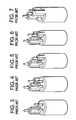
- FIG. 1 and 2 Two embodiments, of the lamp disclosed in the '527 patent are shown in prior art Figures 1 and 2 .
- the pairs of pins are offset relative to each other along the longitudinal axis. This offset resists the formation of an electrical arc between the pairs of pins exteriorly of the arc tube, especially in the presence of the moisture-laden, humid environment of the water purifier.
- the one end cap has a stepped outer end wall having a pair of wall portions lying in mutual parallelism in planes generally perpendicular to the longitudinal axis.
- the first pair of pins is supported on, and extends through, one of the end wall portions for a predetermined distance
- the second pair of pins is supported on, and extends through, the other of the end wall portions for the same predetermined distance.
- the planes of the end wall portions are spaced apart by a predetermined spacing larger than said predetermined distance in order to still further prevent electrical arcing between the pairs of pins exteriorly of the arc tube.
- a barrier wall internally of the one end cap physically separates the electrical connections to the two pairs of pins to resist the formation of an electrical arc between the pairs of pins interiorly of the one end cap.
- the barrier wall is advantageously made of the same non-conductive material as the one end cap.
- lamps There are many different types of lamps that have a base or end cap that can be connected with a socket to provide electrical connections to the lamps.
- the end cap and socket must be constructed to permit easy replacement of the lamp while securely holding the lamp. This may be particularly important in certain applications where vibration or movement of the lamp or lamp fixture could result in unintentional separation between the lamp's end cap and the socket. Additionally, the electrical connections must remain secure.
- the contact pins may become misaligned or bent due to their extension or projection from the base of the lamp, preventing their insertion into a socket. It may also be possible to insert the end cap into a socket such that the contacts are not connected with the proper terminals in the socket, resulting in improper operation of the lamp. Also, on a typical "slide into place" male/female pin connector there is no locking or twist locking and thus the pins may slide out and become disconnected easily by vibration for example.
- U.S. Patent 5,166,527 ('527), which uses a stepped base with pins connector.
- the '527 patent discloses a lamp or bulb, used as an ultraviolet lamp for use in an air or water purifier, comprising an elongated, hollow arc tube extending along a longitudinal axis between opposite end regions.
- the tube contains a gas, preferably noble gas with or without additives.
- a pair of electrodes is spaced apart along the longitudinal axis.
- the electrodes are respectively mounted within the arc tube at the end regions thereof.
- a pair of end caps is respectively mounted at the end regions of the arc tube.
- a first electrical contact or pair of electrical contacts or terminal pins extends in mutual parallelism along the longitudinal axis and is electrically connected to one or both of the electrode lead wires.
- a second electrical contact or pair of electrical contacts or terminal pins extends in mutual parallelism along the longitudinal axis and is electrically connected to one or both of the other of the electrode lead wires. Both pairs of pins are mounted on, and extend outwardly along the longitudinal axis of, one of the end caps.
- a wire conductor is, or two wire conductors are, located exteriorly of the tube and electrically connected to one pin or one pair of pins at one end region of the tube, as well as to the electrode at the other end region of the tube. This design is mainly designed to prevent electrical arcing and does not lock in place.
- US 6 641 419 B1 discloses a device designed to couple with a socket, comprising: a cylindrical body; a sheath made from a non-conductive material and extending from an end of the cylindrical body in a direction parallel to an axis of the cylindrical body; a first female pin connector provided within the sheath and structured such that a male pin connector can be coupled therewith.
- GB 694 114 A and US 6 165 013 A disclose a device comprising a female pin connector provided within a sheath, the socket comprising: a cylindrical body; a cavity provided in an end of the cylindrical body; a first male pin connector provided within the cavity; wherein the cavity is structured so that the sheath of the device can be received within the cavity.
- lamps of proper wattage be used for safety, heat, and fire concerns.
- a unique keying system that only allows lamps of proper wattage to be inserted into the base will also help safety.
- a safety lamp device particularly a radiation lamp
- a radiation lamp which will provide a reliable, locking, and secure from movement, electric connection, yet be relatively inexpensive, uncomplicated, durable, rugged, and simple to implement with smooth operation and with reduced force and stress on the lamp for safety purposes.
- a lamp that reduces the chance of electrical shock is needed for safety purposes.
- a lamp base according to claim 1 having at least one female terminal pin mounted on and extending outwardly along a longitudinal axis of an end cap, also known as the base, of the lamp.
- the pins may be offset relative to one another along the longitudinal axis.
- the above-described end cap configuration for the lamp may be mated to a complimentary shaped receptacle known as a socket bring subject matter of claim 2.
- the socket may be wired to a power source.
- the utilization of one at least one female terminal pin located on the lamp base leads to improved lamp configurations in that polarization between the pairs of pins are more easily ensured; and the mating of the end cap and receptacle may be stronger.
- the designs will further allow for matching of the lamp and connector to a specific power supply to reduce the chance of connecting an ultraviolet lamp into an improperly matched power supply.
- the lamp of this invention is preferably an ultraviolet lamp and finds particular application for use in a water, other liquid, or air purifier.
- FIGURES 1-7 are respective views of end caps used in ultraviolet lamps in accordance with the prior art; FIGURES 8-74 and 91-92 are not according to the invention.
- FIGURE 8 is a cross-sectional view along the longitudinal axis of a water purifier employing the ultraviolet lamp
- FIGURE 9 is a cross-sectional elevation view along the line 9-9 of FIGURE 8 ;
- FIGURE 10 is a perspective elevation view of a first embodiment of an end cap for a lamp
- FIGURE 10A is a cross-sectional elevation view along the line 10A-10A of FIGURE 10 ;
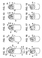
- FIGURES 11-14 are perspective elevation views of second, third, fourth and fifth embodiments of end caps
- FIGURES 15-19 are perspective elevation views of sockets for the end caps of FIGURES 10-14 , respectively;
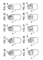
- FIGURES 20-24 are perspective elevation views of additional embodiments of end caps having female recesses .
- FIGURES 25-29 are perspective elevation views of sockets for the end caps of FIGURES 20-24 , respectively.
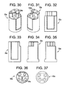
- FIGURES 30-31 are perspective views of an embodiment of a socket useable with the lamp base shown in Figs. 38-45 .
- FIGURES 32-35 are side views of the embodiment shown in Figs. 30-31 .
- FIGURE 36 is a top plan view of the embodiment shown in Figs. 30-35
- FIGURE 37 is a bottom plan view of the embodiment shown in Fig. 30-35 .
- FIGURES 38-39 are perspective views of a lamp base useable with the socket of shown in Figures 30-37 .
- FIGURES 40-43 are side views of the base shown in Figs. 38-39 .
- FIGURE 44 is a top plan view of the base shown in Figs. 38-43
- FIGURE 45 is a bottom plan view of the base shown in Figs. 38-44 .
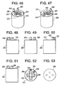
- FIGURES 46-53 are various views of a socket comprising male pin connectors.
- FIGURES 54-61 are various views of a lamp base comprising at least one female pin connector.
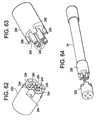
- FIGURE 62 is a perspective view of a socket comprising male pin connectors .
- FIGURE 63 is a perspective view of a lamp base comprising at least one female pin connector.
- FIGURE 64 is an exploded perspective view of an assembly of a lamp with a lamp base and a socket.
- FIGURES 65-66 are various views of a socket comprising male pin connectors.
- FIGURES 67-68 are various views of a lamp base comprising at least one female pin connector.
- FIGURE 69 is a top plan view of a socket comprising male pin connectors and keys.
- FIGURES 70-74 are top plan views of a lamp base showing at least some possible configurations of pin connectors.
- FIGURES 75-78 are various views of a lamp base comprising at least one female pin connector and at least one male pin connector according to an embodiment of the present invention.
- FIGURES 79-84 are various views of a socket comprising at least one female pin connector and at least one male pin connector according to an embodiment of the present invention.
- FIGURE 81 is a side view of a lamp base comprising at least one female pin connector and at least one male pin connector according to an embodiment of the present invention.
- FIGURE 82 is a side view of a socket comprising at least one female pin connector and at least one male pin connector according to an embodiment of the present invention.
- FIGURE 85 is a perspective view of a lamp base comprising at least one female pin connector and at least one male pin connector according to an embodiment of the present invention.
- FIGURE 86 is a perspective view of a lamp base comprising at least one female pin connector and at least one male pin connector according to an embodiment of the present invention.
- FIGURE 87 is a perspective view of a socket comprising at least one female pin connector and at least one male pin connector according to an embodiment of the present invention.
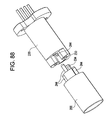
- FIGURE 88 is a perspective view of a lamp base and a socket according to an embodiment of the present invention.
- FIGURES 89-90 are perspective views of a lamp base and a socket according to an embodiment of the present invention.
- FIGURE 91 is an exploded perspective view of a lamp base and an adapter.
- FIGURE 92 is an assembled perspective view of a lamp base and an adapter .
- reference numeral 10 generally identifies a water purifier having a cylindrical housing 12 extending along a longitudinal axis.
- a hollow, axially-extending sleeve 14 is centrally mounted within the housing 12 between apertured support walls 18, 20 spaced apart along the longitudinal axis.
- a water inlet 22 admits pressurized water to be purified into the space 16.
- a water outlet 24 discharges the purified water from the space 16.
- the space 16 serves as a flow-through passage for the water contained therein which, during the course of its flow, is exposed to ultraviolet radiation as described below.
- a removable cover 26 overlies the support wall 18 at one end of the housing 12.
- the cover 26 is detachably coupled to the housing 12 by a set of threaded fasteners 28 to permit access to the interior of the sleeve 14 through the aperture of the support wall 18.
- An electrical socket 30 is removably mounted within the aperture of the support wall 18.
- An ultraviolet lamp 32 in accordance with this invention is slidably inserted into the interior of the sleeve 14 through the aperture of the support wall 18.
- An electrical connection, as described below, is made with the socket 30. In operation, the lamp 32 emits ultraviolet radiation of sufficient intensity to kill microorganisms in the water, other liquid or air contained in the space 16 to purify the same for domestic and commercial applications.
- the lamp 32 includes an elongated, hollow, sealed, arc tube 34 constituted of a light-transmissive material, e.g. silica quartz or other ultraviolet transmitting glass tube.
- the tube 34 has opposite end regions 36,38 spaced apart along the longitudinal axis.
- a gas preferably mercury vapor with or without additives, is sealingly contained within the tube.
- a pair of electrodes 40, 42 is respectively mounted within the tube at the end regions 36, 38.
- a pair of end caps 44, 46 constituted of a non-conducting material, e.g. ceramic, is respectively mounted at the end regions 36, 38 over the sealed end regions of the tube.
- Each end cap has a bore having a closed base against which a sealed end region of the tube abuts when the sealed end region is inserted fully into a respective end cap.
- End cap 44 (best show in FIGURES 10 and 10A ) also has a barrier wall 70a, 70b, extending between semi-circular bases 72, 74 such that bases 72, 74 are stepped with base 72 being the upper or distal base and base 74 being the lower or proximal base.
- a male member 75 extends laterally from barrier wall 70a, 70b, along lower base 74. Member 75 is centrally positioned along wall 70a, 70b thus splitting the wall into the two sections 70a and 70b. Member 75 has a height which is equal to the distance between respective bases 72 and 74. Member 75 also acts to divide lower base 74 into two symmetrical sections (each comprising an approximately 90 degree quadrant).
- a first pair of electrical contacts or terminal pins 48, 50 extends in mutual parallelism along the longitudinal axis, and is mounted on, and extends outwardly of, the end cap 44 (through base 72).
- a second pair of electrical contacts or terminal pins 52, 54 also extends in mutual parallelism along the longitudinal axis, and is also mounted on, and extends outwardly of, the same end cap 44 (through base 74). Pins 52 and 54 are separated from one another by member 75.
- the pins 48, 50 extend into interior compartment 76, and the pins 52, 54 extend into compartment 78 (see FIGURE 10A ).
- the pins 48, 50 are electrically connected within end cap 44 to one end of a wire conductor 56.
- the conductor 56 is located exteriorly of the tube 34, and extends along the longitudinal axis to the opposite end cap 46 wherein the other end of the conductor 56 is connected to the electrode 42.
- the pins 52, 54 are electrically connected within the end cap 44 to the electrode 40.
- the barrier wall 70a, 70b physically separates the pairs of pins.
- the end cap 44 has a stepped, outer end wall having a pair of semi-circular end wall portions 72, 74 lying in mutual parallelism in planes generally perpendicular to the longitudinal axis.
- the socket 30 has a complementary stepped, outer end wall together with a centrally located recess 76. During mating, the pins 48, 50, 52, 54 will be received into respective sockets 78, 80, 82, 84 while member 75 is received into mating recess 76.
- a set of centering rings 62, 64 preferably constituted of a synthetic plastic material, is located on tube 34, being placed thereon before the end caps are attached to the end regions of the tube 34.
- the rings 62, 64 coaxially surround the tube 34 and frictionally engage and support the tube, and assist in centering the tube within sleeve 14.
- FIGURES 11-14 additional embodiments of the end cap depicted in FIGURE 10 are shown. All of these end caps have a similar configuration to that shown in FIGURE 10 including a pair of parallel but longitudinally displaced semi-circular bases 72, 74 having a barrier wall 70a, 70b, extending therebetween so as to form a stepped base.
- a male member or extension extends centrally outwardly from barrier wall 70a, 70b. While this male extension was in the form of a relatively thin wall 75 in the end cap 44 of FIGURE 10 , the male extension takes on a differing geometric shape in the various embodiments shown in FIGURES 11-14 .
- the end cap 86 in FIGURE 11 has a rounded arcuate shape (e.g., V-shaped, semi-circular shaped) extension 102 extending between barrier wall sections 70a and 70b.
- the end cap 88 in FIGURE 12 has an extension 104 in the shape of a rectangular box which includes a pair of opposed sidewalls 106, 108 which extend outwardly from and perpendicularly to respective barrier wall sections 70a and 70b.
- the end cap 90 of FIGURE 13 also has a box like extension 110 which is similar to extension 104 (in FIGURE 12 ); however, extension 112 has a more square cross-section relative to the rectangular cross-section of extension 104.
- barrier wall sections 70a and 70b in FIGURE 13 are relatively larger than the respective barrier wall sections 70a and 70b in FIGURE 12 .
- End cap 92 in FIGURE 14 is a V-shaped triangular shape extension member 112 which forms the divider between barrier wall sections 70a and 70b.
- FIGURES 11-14 have in common the feature of FIGURE 10 wherein a male member extends outwardly from barrier wall 70a, 70b, and is coextensive with stepped (that is longitudinally displaced) base sections 72, 74.
- the male member may have any suitable configuration besides those shown in FIGURES 10-14 and that such configuration may be symmetrical, asymmetrical, spherical, conical, aspheric or any other desired shapes.
- receptacle 94 of FIGURE 16 has a rounded arcuate shaped recess 114 for receiving and mating with rounded or U-shaped extension 102 in FIGURE 11 .
- receptacle 96 has a rectangular shaped recess 116 which is sized and configured to mate with and be received by rectangular extension 104 in FIGURE 12 .
- Receptacle 98 in FIGURE 18 has a square shaped recess 118 for mating with and being received by square shaped extension 110 in FIGURE 13 while receptacle 100 of FIGURE 19 has a V-shaped recess 120 for mating with and being received by V-shaped extension 112 in FIGURE 14 .
- the receptacles of FIGURES 15-19 may include a recess having any desired shape, so long as the shape is complimentary to, and can be received by, the shape of the extensions in the mating end cap.
- FIGURES 20-24 and 38-45 are similar to the respective end caps shown in FIGURES 10-14 with the only difference being that the male extension has been substituted with the female recess in FIGURES 20-24 .
- end cap 44' includes a narrow recess 122 (similar to the recess 76 shown in FIGURE 15 ), end cap 86' and 86a include an arcuate shaped recess 124, 124a (similar to the recess 114 in FIGURE 16 ), end cap 88' includes a rectangularly shaped recess 126 (similar to the recess 116 in FIGURE 17 ), end cap 90' of FIGURE 23 includes a square shaped recess 128 (similar to the recess 118 in FIGURE 18 ) and end cap 92' of FIGURE 24 includes a V-shaped recess 130 (similar to the V-shaped recess 120 of FIGURE 19 ).
- receptacles or bases are shown which are configured to mate with the end caps of FIGURES 20-24 and 38-45 , respectively.
- receptacle 30' of FIGURE 25 includes male extension 132 which is sized and configured to be received by recess 122 in FIGURE 20 .
- Receptacle 30a of FIGURES 30-37 includes male extension 134a which is sized and configured to be received by recess 124a in FIGURE 38.
- Fig. 38 also shows how semi-circular bases 72a may contain an asymmetrical section 72b which may be added to help ensure that unauthorized parts are unable to be used.
- FIGURES 30-37 may be used with the corresponding end caps or bases shown in FIGURES 38-45 or the designs may be exchanged with each other, i.e., the end cap may look like the receptacle or base or vice versa.
- Receptacle 94' of FIGURE 26 includes arcuate shaped male extension 134 which is sized and configured to be received by arcuate recess 124 in FIGURE 21 .
- receptacle 96' of FIGURE 27 includes a rectangular extension 136 which is sized and configured to be received by rectangular recess 126 of FIGURE 22
- receptacle 98' of FIGURE 28 includes a square shaped extension 138 which is sized and configured to be received by squared shaped recess 128 in FIGURE 23
- receptacle 100' of FIGURE 29 includes a triangular shaped extension 140 which is sized and configured to be received by rectangular shaped recess 130 in FIGURE 24 .
- the cover 26 is removed, and a lamp 32 is inserted into the interior of the sleeve 14 via the aperture in the support wall 18.
- the socket 30 is connected to the pins 48, 50, 52, 54.
- the cover 26 is installed on the housing 12.
- Electrical wires 66,68 extend exteriorly of the socket to a non-illustrated electrical power supply. A voltage difference across the wires 66,68 is applied to both electrodes 40, 42 causing an electrical discharge within the tube. This discharge causes ultraviolet radiation to be emitted. This radiation passes through the light-transmissive wall of the sleeve 14 to irradiate the water contained in the space 16.
- the aforementioned barrier wall 70a, 70b prevents arcing interiorly of the end cap 44 by physically separating the electrical connections between the pins 48, 50 and the wire conductor, on the one hand, and the electrical connections between the pins 52, 54 and the electrode 40, on the other hand. The pairs ofpins are thus effectively isolated.
- a lamp base 200 may include at least one female pin connector 240 and a socket 220 may include at least one male pin connector 244, as seen in Figures 46-90 .
- Figures 46-53 show various views of a socket 220.
- the socket 220 may be generally cylindrical in shape, for example, a cylindrical body made of a non-conductive material.
- a cavity 230 may be provided on one end 272 of the socket.
- the cavity is formed in a cross shape, although it will be appreciated that many different shapes of cavity 230 are possible.
- At least one male pin connector 244 may be provided within the cavity 230.
- four male pin connectors 244 are arranged at the four ends of cross-shaped cavity 230, although it will be appreciated that the male pin connectors 244 may be arranged in other patterns and in varying number.
- Male pin connectors 244 may be connected to an external power supply, for example, to supply electrical power to socket 220. It will also be appreciated that because male pin connectors 244 are arranged within cavity 230, male pin connectors 240 are protected from damage from inadvertent contact or miscoupling, thus preventing bending or breaking of the male pin connectors 240.
- socket 220 may also include at least one key protrusion 250.
- two key protrusions 250 are located on the outer periphery of one end 272 of socket 220.
- the key protrusions 250 are designed to mate with a corresponding key recess 254 of the lamp base 200 (described in more detail below).
- FIGS 54-61 illustrate various views of a lamp base 200 .
- Lamp base 200 is generally cylindrical in shape, for example, a cylindrical body, and is designed to fit over one end of a lamp, for example arc tube 34.
- a sheath 234 may extend from one end 270 of the lamp base 200 in a direction along the long axis of the cylindrical lamp base 200.
- Sheath 234 is made of a non-conductive material, for example ceramic, and may be the same material as lamp base 200 or a different material. Additionally, sheath 234 may be integrally formed with lamp base 200, or may be attached to lamp base 200 through other means such as by adhesive. In the particular embodiment shown in Figures 54-61 , the sheath 234 is formed in a cross shape, although it will be appreciated that many different shapes of the sheath 234 are possible.
- lamp base 200 may also include at least one female pin connector 240 provided within sheath 234, such that sheath 234 surrounds the sides of the female pin connectors 240 while leaving an end of the female pin connectors open or exposed for coupling.
- female pin connectors 240 are provided at the ends of the cross-shaped sheath 234, but it will be appreciated that female pin connectors 240 may be arranged in other patterns and in varying number. It will also be appreciated that because female pin connectors 240 are provided within the sheath 234, female pin connectors 240 are protected from damage caused by inadvertent contact or miscoupling, for example.
- female pin connectors on the lamp base is important because it results in advantages in the manufacturing process. For example, it is easier to manufacture a lamp base using female pin connectors, instead of male pin connectors as done in conventional devices, because female pin connectors can be mounted using a crimping step. Accordingly, a soldering connection is not necessary for the female pin connectors, thus simplifying the manufacturing process.
- Figures 54-61 show that a lamp base 200 may include key recesses 254.
- two key protrusions 254 are located on the outer periphery of one end 270 of lamp base 200.
- key recesses 254 are designed to mate with corresponding key protrusions 250 of the lamp base 200, as described above.
- the lamp base 200 is designed to couple with socket 220 so that an electrical connection is established between lamp base 200 and socket 200.
- the lamp base 200 shown in Figures 54-61 is designed to couple with the socket 220 shown in Figures 46-53 .
- a number of the structures described above are important in providing a secure coupling between socket 220 and lamp base 200 as well as improving safety and performance.
- the sheath 234 is designed to fit within the cavity 230 of socket 220. This correspondence of the shapes of the sheath 234 and the cavity 230 helps to align the male pin connectors 244 of the socket 220 with the female pin connectors 240 of the lamp base.
- sheaths 234 and cavities 230 may be used to ensure proper angular orientation of the pin connectors.
- the sheath 234 surrounding the female pin connectors may be "T” shaped (234a, 234d), "U”-shaped (234b, 234e), "Z”-shaped (234c), or another appropriate shape.
- one useful class of sheaths is sheaths wherein a transverse cross section of the sheath (and the corresponding cavity) is rotationally asymmetric about a center of the end of the lamp base 200.
- a transverse cross section of the sheath and the corresponding cavity
- the lamp base 200 with a sheath that has a rotationally asymmetric cross section is rotated around an axis passing through its center, there is only one possible angular orientation in which the lamp base will couple with a corresponding socket.
- sheaths 234a-234b and 234d-234e shown in Figures 70-71 and 73-74 are coupled with a corresponding cavity, it ensures that the pin connectors can be coupled in only one possible alignment.
- This feature is important to ensure proper operation of the lamp, i.e., the lamp may not work or may be damaged if the pin connectors of the lamp base are not connected to an appropriate power supply. Additionally, the mating of sheaths and cavities can be used as a safety feature, for example to ensure that a lamp rated for a particular power supply is not inadvertently coupled to a power supply that is too powerful, or to prevent misalignment of the connector, thus preventing a fire or electrical shock hazard.
- key protrusions 250.and key protrusions 254 can also help to ensure proper alignment of lamp base 200 and socket 220.
- lamp base 200 and socket 220 cannot be coupled unless key protrusions 250 are aligned with key recesses 254. As described above, this helps to ensure proper angular alignment of the pin connectors, as well as serving as a safety feature to ensure that only appropriate lamp bulbs are coupled with appropriate sockets.
- Figure 69 shows that a variety of configurations are possible for the key protrusions 250, and, consequently, the key recesses 254.
- Figure 69 shows that key protrusions can be placed anywhere along the periphery of the socket.
- the lamp base and socket assembly itself can be made rotationally asymmetric through the use of key protrusion and key recesses.
- a cross shaped sheath 234 and cavity 230 may be rotationally symmetrical.
- key protrusions 250 and key recesses 254 it is clear that lamp base 200 and socket 220 can only be coupled together in one possible orientation.
- the lamp base and socket assembly will include either a sheath and cavity combination that is rotationally asymmetric (as in Figures 70-71 and 73-74 ), or a key protrusion and key recess combination that is rotationally asymmetric (as in Figures 66 and 67 ). Additionally, at least an embodiment may include both of these features, i.e., rotational asymmetry in both the sheath and cavity as well as the key protrusion and key recess.
- the alignment features described above can ensure that there is only one possible way for a lamp base to fit into the socket.
- the alignment features ensure that a female pin connector on the socket always couples with the appropriate male pin connector on the socket. This is an important safety feature because it prevents the pin connectors from mistakenly being connected to the wrong polarity of a power source, for example, which could damage the lamp.
- the alignment features described above can help to prevent damage to lamps by ensuring proper coupling.
- an appropriate socket may have a given configuration of key protrusions and cavity and unless the lamp base is a properly corresponding lamp base that has complementary key recesses and sheath, the lamp base cannot be coupled to the socket. This helps to ensure that the proper model of lamp is used with a particular socket.
- male pin connectors 244 may include a male neck 246.
- Male neck 246 is a portion of male pin connector that has a slightly smaller radius than the portions of the male pin connector 246 immediately adjacent to the male neck 246.
- the female pin connectors 240 on the corresponding lamp base 200 may include a female neck 242.
- Female neck 242 is a portion of a female pin connector that has a slightly smaller inner radius than the portions of the female pin connector immediately adjacent to the female neck 242.
- lamp base is not limited to four female pin connectors and that the socket is not limited to four male pin connectors.
- Figures 76-82 illustrate at least one possible embodiment according to the invention wherein lamp base 200 is provided with three male pin connectors 244 and one female pin connector 240, and socket 220 is provided with three female pin connectors 240 and one male pin connector 244.
- Figures 75-78 also show another possible feature for ensuring proper alignment of a lamp base and socket.
- lamp base 200 is provided with a step portion 280, and a male pin connector 244 is provided on step portion 280.
- the male pin connector 244 provided on step portion 280 is provided at a different level than the other male pin connectors 244. This feature helps to ensure that lamp base 200 can only be coupled with socket 220 in a particular orientation.
- a lamp base 300 can be fitted with an adaptor 260 to take advantage of the operational and safety features described above.
- Figure 91 shows a lamp base 300 with four male pin connectors 244. Because there are no keys, sheaths, cavities, step portions or similar structures on lamp base 300, it will be appreciated that lamp base 300 may improperly couple with a socket. For example, the male pin connectors 244 may be rotated from their proper positions.
- lamp base 300 can be fitted with adaptor 260.
- adaptor 260 converts a lamp base 300 with for male pin connectors 244 into a lamp base with two male pin connectors 244, a male pin connector 244 on a step portion 280, and a female pin connector 240 within a sheath 234.
- existing lamp bases can be upgraded through the use of an adaptor to ensure that the lamp base only couples in a particular way with appropriate sockets. This allows a user to achieve the operation and safety advantages described above without have to discard previously purchased lamps.
Landscapes
- Health & Medical Sciences (AREA)
- Engineering & Computer Science (AREA)
- Life Sciences & Earth Sciences (AREA)
- Organic Chemistry (AREA)
- Animal Behavior & Ethology (AREA)
- Environmental & Geological Engineering (AREA)
- Water Supply & Treatment (AREA)
- Chemical & Material Sciences (AREA)
- Toxicology (AREA)
- Epidemiology (AREA)
- Hydrology & Water Resources (AREA)
- General Health & Medical Sciences (AREA)
- Public Health (AREA)
- Veterinary Medicine (AREA)
- Microelectronics & Electronic Packaging (AREA)
- Physical Water Treatments (AREA)
- Arrangement Of Elements, Cooling, Sealing, Or The Like Of Lighting Devices (AREA)
- Fastening Of Light Sources Or Lamp Holders (AREA)
Description
- This invention generally relates to improvements in lamps, especially ultraviolet lamps used in air and water purifiers.
- Ultraviolet air and water or other liquid purifiers are known for disinfecting contaminated air or water or other liquid for domestic or commercial use. Such purifiers include at least one lamp for emitting ultraviolet radiation into a chamber, duct or other apparatus such that contaminated air or water or other liquid passes over the lamp to kill microorganisms therein. In conventional manner, the lamp includes two electrodes spaced apart within an elongated arc tube containing a gas, particularly noble gas with or without additives. A pair of end caps (i.e., bases) are mounted at the ends of the tube. Each electrode contains two lead wires from the lamp seal each of which, or in some instances only one, are electrically connected to respective contact(s) or terminal pin(s). The lamp is typically inserted endwise into a sleeve installed in the water, other liquid or air purifier with or without the use of a quartz sleeve. To simplify insertion and electrical connection, the pins are conveniently mounted on one of the end caps. When the electrodes are energized by voltage from an electrical power supply, an electrical discharge is initiated in the gas between the electrodes. This discharge results from a reaction between the electrical energy, gas and mercury to produce ultraviolet radiation to be emitted from the lamp in a manner well known in the art.
- An example of an ultraviolet lamp of the type described above is disclosed in
U.S. Patent 5,166,527 ('527). The '527 patent discloses a lamp, especially useful as an ultraviolet lamp for use in a water purifier, comprising an elongated, hollow arc tube extending along a longitudinal axis between opposite end regions. The tube contains a gas, preferably noble gas with or without additives. A pair of electrodes is spaced apart along the longitudinal axis. The electrodes are respectively mounted within the arc tube at the end regions thereof. A pair of end caps is respectively mounted at the end regions of the arc tube. A first electrical contact or pair of electrical contacts or terminal pins extends in mutual parallelism along the longitudinal axis and is electrically connected to one or both of the electrode lead wires. A second electrical contact or pair of electrical contacts or terminal pins extends in mutual parallelism along the longitudinal axis and is electrically connected to one or both of the other of the electrode lead wires. Both pairs of pins are mounted on, and extend outwardly along the longitudinal axis of, one of the end caps. A wire conductor is, or two wire conductors are, located exteriorly of the tube and electrically connected to one pin or one pair of pins at one end region of the tube, as well as to the electrode at the other end region of the tube. - Two embodiments, of the lamp disclosed in the '527 patent are shown in prior art
Figures 1 and 2 . As shown inFigures 1 and 2 , the pairs of pins are offset relative to each other along the longitudinal axis. This offset resists the formation of an electrical arc between the pairs of pins exteriorly of the arc tube, especially in the presence of the moisture-laden, humid environment of the water purifier. - Still referring to prior art
Figures 1 and 2 , the one end cap has a stepped outer end wall having a pair of wall portions lying in mutual parallelism in planes generally perpendicular to the longitudinal axis. The first pair of pins is supported on, and extends through, one of the end wall portions for a predetermined distance, and the second pair of pins is supported on, and extends through, the other of the end wall portions for the same predetermined distance. The planes of the end wall portions are spaced apart by a predetermined spacing larger than said predetermined distance in order to still further prevent electrical arcing between the pairs of pins exteriorly of the arc tube. A barrier wall internally of the one end cap physically separates the electrical connections to the two pairs of pins to resist the formation of an electrical arc between the pairs of pins interiorly of the one end cap. The barrier wall is advantageously made of the same non-conductive material as the one end cap. - In addition to the two-tiered stepped bases of the '527 patent, other multi-tiered bases have been manufactured including those bases shown in prior art
Figures 3-7 . - Although well-suited for their intended purposes, there continues to be a need for improved lamp base designs, particularly ultraviolet lamps.
- There are many different types of lamps that have a base or end cap that can be connected with a socket to provide electrical connections to the lamps. The end cap and socket must be constructed to permit easy replacement of the lamp while securely holding the lamp. This may be particularly important in certain applications where vibration or movement of the lamp or lamp fixture could result in unintentional separation between the lamp's end cap and the socket. Additionally, the electrical connections must remain secure.
- In some applications where a multiplicity of contact pins and/or pin orientations is utilized, it is often difficult to align the contact pins to make the electrical connection necessary to operate the lamp. Often, the contact pins may become misaligned or bent due to their extension or projection from the base of the lamp, preventing their insertion into a socket. It may also be possible to insert the end cap into a socket such that the contacts are not connected with the proper terminals in the socket, resulting in improper operation of the lamp. Also, on a typical "slide into place" male/female pin connector there is no locking or twist locking and thus the pins may slide out and become disconnected easily by vibration for example.
- An example of an ultraviolet lamp of the type described above is disclosed in
U.S. Patent 5,166,527 ('527), which uses a stepped base with pins connector. The '527 patent discloses a lamp or bulb, used as an ultraviolet lamp for use in an air or water purifier, comprising an elongated, hollow arc tube extending along a longitudinal axis between opposite end regions. The tube contains a gas, preferably noble gas with or without additives. A pair of electrodes is spaced apart along the longitudinal axis. The electrodes are respectively mounted within the arc tube at the end regions thereof. A pair of end caps is respectively mounted at the end regions of the arc tube. A first electrical contact or pair of electrical contacts or terminal pins extends in mutual parallelism along the longitudinal axis and is electrically connected to one or both of the electrode lead wires. A second electrical contact or pair of electrical contacts or terminal pins extends in mutual parallelism along the longitudinal axis and is electrically connected to one or both of the other of the electrode lead wires. Both pairs of pins are mounted on, and extend outwardly along the longitudinal axis of, one of the end caps. A wire conductor is, or two wire conductors are, located exteriorly of the tube and electrically connected to one pin or one pair of pins at one end region of the tube, as well as to the electrode at the other end region of the tube. This design is mainly designed to prevent electrical arcing and does not lock in place. - As noted in WO/2006/ 136026 to Elku et al. which is a variation of the slide-on pin connector above, a potential problem with this approach is that in many applications, the radiation lamp is immersed in a flow of water and turbulence created within that water treatment system invariably imparts a vibratory motion to the lamps. This frequently results in the lamp being vibrated or shaken loose of its electrical connection base or socket thereby causing the lamp to be rendered completely or intermittently inoperative. When such an event occurs, the water being treated may not be fully disinfected. The prior art has attempted to address this problem by using a relatively complicated mechanical connection (e.g., a so-called "push-and-twist" connection) to secure the lamp to the connection base. See, for example, United States patent
5,422,487 to Sauska et al. and United States patent6,884,103 to Kovacs. The potential problem with these approaches is the complexity of the mechanical connection between the lamp and the base unit requiring the use of springs, specialized connection lugs and the like. Further, a connection system which is predicated on a dual motion system such that pushing and twisting if used incorrectly for example may give rise to higher incidents of lamp breakage, electrical shock, and other damage to the lamp by field personal. Therefore, eliminating a forceful "push" necessary to deflect a heavy locking spring in a "push and twist" lock would be beneficial because the typically glass lamp would be subject to reduced force and stress.
US 6 641 419 B1 discloses a device designed to couple with a socket, comprising: a cylindrical body; a sheath made from a non-conductive material and extending from an end of the cylindrical body in a direction parallel to an axis of the cylindrical body; a first female pin connector provided within the sheath and structured such that a male pin connector can be coupled therewith.
GB 694 114 A US 6 165 013 A disclose a device comprising a female pin connector provided within a sheath, the socket comprising: a cylindrical body; a cavity provided in an end of the cylindrical body; a first male pin connector provided within the cavity; wherein the cavity is structured so that the sheath of the device can be received within the cavity. - Also, it is important that lamps of proper wattage be used for safety, heat, and fire concerns. Thus, a unique keying system that only allows lamps of proper wattage to be inserted into the base will also help safety.
- Accordingly, there remains the need in the art for a safety lamp device, particularly a radiation lamp, which will provide a reliable, locking, and secure from movement, electric connection, yet be relatively inexpensive, uncomplicated, durable, rugged, and simple to implement with smooth operation and with reduced force and stress on the lamp for safety purposes. Also, a lamp that reduces the chance of electrical shock is needed for safety purposes.
- Thus, there continues to be a need for improved lamp base designs, particularly ultraviolet lamps.
- In accordance with at least an embodiment of the present invention, a lamp base according to claim 1 is provided having at least one female terminal pin mounted on and extending outwardly along a longitudinal axis of an end cap, also known as the base, of the lamp. The pins may be offset relative to one another along the longitudinal axis.
- The above-described end cap configuration for the lamp may be mated to a complimentary shaped receptacle known as a socket bring subject matter of claim 2. The socket may be wired to a power source.
- The utilization of one at least one female terminal pin located on the lamp base leads to improved lamp configurations in that polarization between the pairs of pins are more easily ensured; and the mating of the end cap and receptacle may be stronger. The designs will further allow for matching of the lamp and connector to a specific power supply to reduce the chance of connecting an ultraviolet lamp into an improperly matched power supply.
- The lamp of this invention is preferably an ultraviolet lamp and finds particular application for use in a water, other liquid, or air purifier.
- Embodiments will now be described, by way of example only, with reference to the accompanying drawings which are meant to be exemplary, not limiting, and wherein like elements are numbered alike in several Figures, in which:
-
FIGURES 1-7 are respective views of end caps used in ultraviolet lamps in accordance with the prior art;
FIGURES 8-74 and91-92 are not according to the invention. -
FIGURE 8 is a cross-sectional view along the longitudinal axis of a water purifier employing the ultraviolet lamp; -
FIGURE 9 is a cross-sectional elevation view along the line 9-9 ofFIGURE 8 ; -
FIGURE 10 is a perspective elevation view of a first embodiment of an end cap for a lamp; -
FIGURE 10A is a cross-sectional elevation view along theline 10A-10A ofFIGURE 10 ; -
FIGURES 11-14 are perspective elevation views of second, third, fourth and fifth embodiments of end caps; -
FIGURES 15-19 are perspective elevation views of sockets for the end caps ofFIGURES 10-14 , respectively; -
FIGURES 20-24 are perspective elevation views of additional embodiments of end caps having female recesses ; and -
FIGURES 25-29 are perspective elevation views of sockets for the end caps ofFIGURES 20-24 , respectively. -
FIGURES 30-31 are perspective views of an embodiment of a socket useable with the lamp base shown inFigs. 38-45 . -
FIGURES 32-35 are side views of the embodiment shown inFigs. 30-31 . -
FIGURE 36 is a top plan view of the embodiment shown inFigs. 30-35 -
FIGURE 37 is a bottom plan view of the embodiment shown inFig. 30-35 . -
FIGURES 38-39 are perspective views of a lamp base useable with the socket of shown inFigures 30-37 . -
FIGURES 40-43 are side views of the base shown inFigs. 38-39 . -
FIGURE 44 is a top plan view of the base shown inFigs. 38-43 -
FIGURE 45 is a bottom plan view of the base shown inFigs. 38-44 . -
FIGURES 46-53 are various views of a socket comprising male pin connectors. -
FIGURES 54-61 are various views of a lamp base comprising at least one female pin connector. -
FIGURE 62 is a perspective view of a socket comprising male pin connectors . -
FIGURE 63 is a perspective view of a lamp base comprising at least one female pin connector. -
FIGURE 64 is an exploded perspective view of an assembly of a lamp with a lamp base and a socket. -
FIGURES 65-66 are various views of a socket comprising male pin connectors. -
FIGURES 67-68 are various views of a lamp base comprising at least one female pin connector. -
FIGURE 69 is a top plan view of a socket comprising male pin connectors and keys. -
FIGURES 70-74 are top plan views of a lamp base showing at least some possible configurations of pin connectors. -
FIGURES 75-78 are various views of a lamp base comprising at least one female pin connector and at least one male pin connector according to an embodiment of the present invention. -
FIGURES 79-84 are various views of a socket comprising at least one female pin connector and at least one male pin connector according to an embodiment of the present invention. -
FIGURE 81 is a side view of a lamp base comprising at least one female pin connector and at least one male pin connector according to an embodiment of the present invention. -
FIGURE 82 is a side view of a socket comprising at least one female pin connector and at least one male pin connector according to an embodiment of the present invention. -
FIGURE 85 is a perspective view of a lamp base comprising at least one female pin connector and at least one male pin connector according to an embodiment of the present invention. -
FIGURE 86 is a perspective view of a lamp base comprising at least one female pin connector and at least one male pin connector according to an embodiment of the present invention. -
FIGURE 87 is a perspective view of a socket comprising at least one female pin connector and at least one male pin connector according to an embodiment of the present invention. -
FIGURE 88 is a perspective view of a lamp base and a socket according to an embodiment of the present invention. -
FIGURES 89-90 are perspective views of a lamp base and a socket according to an embodiment of the present invention. -
FIGURE 91 is an exploded perspective view of a lamp base and an adapter. -
FIGURE 92 is an assembled perspective view of a lamp base and an adapter . - Referring now to
FIGURE 8 of the drawings,reference numeral 10 generally identifies a water purifier having acylindrical housing 12 extending along a longitudinal axis. A hollow, axially-extendingsleeve 14 is centrally mounted within thehousing 12 betweenapertured support walls support walls housing 12 and the exterior wall of thesleeve 14, bound aninterior space 16. Awater inlet 22 admits pressurized water to be purified into thespace 16. Awater outlet 24 discharges the purified water from thespace 16. Thespace 16 serves as a flow-through passage for the water contained therein which, during the course of its flow, is exposed to ultraviolet radiation as described below. - A
removable cover 26 overlies thesupport wall 18 at one end of thehousing 12. Thecover 26 is detachably coupled to thehousing 12 by a set of threadedfasteners 28 to permit access to the interior of thesleeve 14 through the aperture of thesupport wall 18. Anelectrical socket 30 is removably mounted within the aperture of thesupport wall 18. Anultraviolet lamp 32 in accordance with this invention is slidably inserted into the interior of thesleeve 14 through the aperture of thesupport wall 18. An electrical connection, as described below, is made with thesocket 30. In operation, thelamp 32 emits ultraviolet radiation of sufficient intensity to kill microorganisms in the water, other liquid or air contained in thespace 16 to purify the same for domestic and commercial applications. - The
lamp 32 includes an elongated, hollow, sealed,arc tube 34 constituted of a light-transmissive material, e.g. silica quartz or other ultraviolet transmitting glass tube. Thetube 34 hasopposite end regions - A pair of
electrodes end regions end caps end regions FIGURES 10 and10A ) also has abarrier wall semi-circular bases bases base 72 being the upper or distal base andbase 74 being the lower or proximal base. Amale member 75 extends laterally frombarrier wall lower base 74.Member 75 is centrally positioned alongwall sections Member 75 has a height which is equal to the distance betweenrespective bases Member 75 also acts to dividelower base 74 into two symmetrical sections (each comprising an approximately 90 degree quadrant). - Still referring to
FIGURE 10 , a first pair of electrical contacts orterminal pins terminal pins Pins member 75. Thepins interior compartment 76, and thepins FIGURE 10A ). - The
pins end cap 44 to one end of awire conductor 56. Theconductor 56 is located exteriorly of thetube 34, and extends along the longitudinal axis to theopposite end cap 46 wherein the other end of theconductor 56 is connected to theelectrode 42. Thepins end cap 44 to theelectrode 40. Thebarrier wall - Thus, as shown in
FIGURE 10 , theend cap 44 has a stepped, outer end wall having a pair of semi-circularend wall portions FIGURE 15 , thesocket 30 has a complementary stepped, outer end wall together with a centrally locatedrecess 76. During mating, thepins respective sockets member 75 is received intomating recess 76. - A set of centering
rings tube 34, being placed thereon before the end caps are attached to the end regions of thetube 34. Therings tube 34 and frictionally engage and support the tube, and assist in centering the tube withinsleeve 14. - Referring now to
FIGURES 11-14 , additional embodiments of the end cap depicted inFIGURE 10 are shown. All of these end caps have a similar configuration to that shown inFIGURE 10 including a pair of parallel but longitudinally displacedsemi-circular bases barrier wall barrier wall thin wall 75 in theend cap 44 ofFIGURE 10 , the male extension takes on a differing geometric shape in the various embodiments shown inFIGURES 11-14 . More specifically, theend cap 86 inFIGURE 11 has a rounded arcuate shape (e.g., V-shaped, semi-circular shaped)extension 102 extending betweenbarrier wall sections end cap 88 inFIGURE 12 has anextension 104 in the shape of a rectangular box which includes a pair ofopposed sidewalls barrier wall sections end cap 90 ofFIGURE 13 also has a box likeextension 110 which is similar to extension 104 (inFIGURE 12 ); however,extension 112 has a more square cross-section relative to the rectangular cross-section ofextension 104. Thus, thebarrier wall sections FIGURE 13 are relatively larger than the respectivebarrier wall sections FIGURE 12 .End cap 92 inFIGURE 14 is a V-shaped triangularshape extension member 112 which forms the divider betweenbarrier wall sections - Significantly, all of the additional embodiments of
FIGURES 11-14 have in common the feature ofFIGURE 10 wherein a male member extends outwardly frombarrier wall base sections FIGURES 10-14 and that such configuration may be symmetrical, asymmetrical, spherical, conical, aspheric or any other desired shapes. - As in the
receptacle 30 shown inFIGURE 15 which receives theend cap 44 inFIGURE 10 , the end caps of the embodiments ofFIGURES 11-14 have similarly complimentary shapedrespective receptacles FIGURES 16-19 , respectively. Thus,receptacle 94 ofFIGURE 16 has a rounded arcuate shapedrecess 114 for receiving and mating with rounded orU-shaped extension 102 inFIGURE 11 . Similarly,receptacle 96 has a rectangular shapedrecess 116 which is sized and configured to mate with and be received byrectangular extension 104 inFIGURE 12 .Receptacle 98 inFIGURE 18 has a square shapedrecess 118 for mating with and being received by square shapedextension 110 inFIGURE 13 whilereceptacle 100 ofFIGURE 19 has a V-shapedrecess 120 for mating with and being received by V-shapedextension 112 inFIGURE 14 . Again, it will be appreciated that the receptacles ofFIGURES 15-19 may include a recess having any desired shape, so long as the shape is complimentary to, and can be received by, the shape of the extensions in the mating end cap. - It will be appreciated that the male extension in the plug ended lamp and the female recess in the complimentary receptacle may be reversed such that the lamp cap will exhibit the recess while the receptacle will exhibit the complimentary male extension for mating with the recess in the cap. Such alternative configurations are shown in the end caps of
FIGURES 20-24 and also inFIGURES. 38-45 . The end caps ofFIGURES 20-24 and38-45 are similar to the respective end caps shown inFIGURES 10-14 with the only difference being that the male extension has been substituted with the female recess inFIGURES 20-24 . Thus, end cap 44' includes a narrow recess 122 (similar to therecess 76 shown inFIGURE 15 ),end cap 86' and 86a include an arcuate shapedrecess recess 114 inFIGURE 16 ), end cap 88' includes a rectangularly shaped recess 126 (similar to therecess 116 inFIGURE 17 ), end cap 90' ofFIGURE 23 includes a square shaped recess 128 (similar to therecess 118 inFIGURE 18 ) and end cap 92' ofFIGURE 24 includes a V-shaped recess 130 (similar to the V-shapedrecess 120 ofFIGURE 19 ). - Similarly, with reference to
FIGURES 25-29 and30-37 , receptacles or bases are shown which are configured to mate with the end caps ofFIGURES 20-24 and38-45 , respectively. Thus, receptacle 30' ofFIGURE 25 includesmale extension 132 which is sized and configured to be received byrecess 122 inFIGURE 20 .Receptacle 30a ofFIGURES 30-37 includesmale extension 134a which is sized and configured to be received byrecess 124a inFIGURE 38. Fig. 38 also shows howsemi-circular bases 72a may contain anasymmetrical section 72b which may be added to help ensure that unauthorized parts are unable to be used. This is a safety feature because improper wattage lamps or improper lamp designs may commonly be attempted to be substituted so theasymmetrical section 72b helps to prevent this unsafe occurrence. The sockets shown onFIGURES 30-37 may be used with the corresponding end caps or bases shown inFIGURES 38-45 or the designs may be exchanged with each other, i.e., the end cap may look like the receptacle or base or vice versa. Receptacle 94' ofFIGURE 26 includes arcuate shapedmale extension 134 which is sized and configured to be received byarcuate recess 124 inFIGURE 21 . Similarly, receptacle 96' ofFIGURE 27 includes arectangular extension 136 which is sized and configured to be received byrectangular recess 126 ofFIGURE 22 , receptacle 98' ofFIGURE 28 includes a square shapedextension 138 which is sized and configured to be received by squared shapedrecess 128 inFIGURE 23 and receptacle 100' ofFIGURE 29 includes a triangular shapedextension 140 which is sized and configured to be received by rectangular shapedrecess 130 inFIGURE 24 . - It will be appreciated that all of the embodiments represent an advance over the stepped cap configuration of the aforementioned '527 patent in that the use of the extension (or alternatively the recess) positioned centrally along the barrier wall will provide improved interlocking between the lamp and the receptacle and will also ensure proper orientation of the respective pins within the recesses of the receptacle.
- In operation, the
cover 26 is removed, and alamp 32 is inserted into the interior of thesleeve 14 via the aperture in thesupport wall 18. After insertion, thesocket 30 is connected to thepins cover 26 is installed on thehousing 12.Electrical wires wires electrodes sleeve 14 to irradiate the water contained in thespace 16. - The
aforementioned barrier wall end cap 44 by physically separating the electrical connections between thepins pins electrode 40, on the other hand. The pairs ofpins are thus effectively isolated. - It will be understood that each of the elements described above, or two or more together, also may find a useful application in other types of constructions differing from the types described above.
- In at least another embodiment, a
lamp base 200 may include at least onefemale pin connector 240 and asocket 220 may include at least onemale pin connector 244, as seen inFigures 46-90 . - For example,
Figures 46-53 show various views of asocket 220. Thesocket 220 may be generally cylindrical in shape, for example, a cylindrical body made of a non-conductive material. On oneend 272 of the socket, acavity 230 may be provided. In the particular embodiment shown inFigures 46-53 , the cavity is formed in a cross shape, although it will be appreciated that many different shapes ofcavity 230 are possible. - Additionally, at least one
male pin connector 244 may be provided within thecavity 230. In the embodiment shown inFigures 46-53 , fourmale pin connectors 244 are arranged at the four ends ofcross-shaped cavity 230, although it will be appreciated that themale pin connectors 244 may be arranged in other patterns and in varying number.Male pin connectors 244 may be connected to an external power supply, for example, to supply electrical power tosocket 220. It will also be appreciated that becausemale pin connectors 244 are arranged withincavity 230,male pin connectors 240 are protected from damage from inadvertent contact or miscoupling, thus preventing bending or breaking of themale pin connectors 240. - Additionally,
Figures 46-53 show thatsocket 220 may also include at least onekey protrusion 250. In the embodiment seen inFigures 46-53 , twokey protrusions 250 are located on the outer periphery of oneend 272 ofsocket 220. However, it will be appreciated that many different configurations ofkey protrusions 250 are possible, including different numbers, shapes, sizes, and placement of key protrusions. Thekey protrusions 250 are designed to mate with a correspondingkey recess 254 of the lamp base 200 (described in more detail below). -
Figures 54-61 illustrate various views of alamp base 200 .Lamp base 200 is generally cylindrical in shape, for example, a cylindrical body, and is designed to fit over one end of a lamp, forexample arc tube 34. Asheath 234 may extend from oneend 270 of thelamp base 200 in a direction along the long axis of thecylindrical lamp base 200.Sheath 234 is made of a non-conductive material, for example ceramic, and may be the same material aslamp base 200 or a different material. Additionally,sheath 234 may be integrally formed withlamp base 200, or may be attached tolamp base 200 through other means such as by adhesive. In the particular embodiment shown inFigures 54-61 , thesheath 234 is formed in a cross shape, although it will be appreciated that many different shapes of thesheath 234 are possible. - Additionally, as seen in
Figures 54-61 ,lamp base 200 may also include at least onefemale pin connector 240 provided withinsheath 234, such thatsheath 234 surrounds the sides of thefemale pin connectors 240 while leaving an end of the female pin connectors open or exposed for coupling. In the particular embodiment shown inFigures 54-61 , fourfemale pin connectors 240 are provided at the ends of thecross-shaped sheath 234, but it will be appreciated thatfemale pin connectors 240 may be arranged in other patterns and in varying number. It will also be appreciated that becausefemale pin connectors 240 are provided within thesheath 234,female pin connectors 240 are protected from damage caused by inadvertent contact or miscoupling, for example. - The use of female pin connectors on the lamp base is important because it results in advantages in the manufacturing process. For example, it is easier to manufacture a lamp base using female pin connectors, instead of male pin connectors as done in conventional devices, because female pin connectors can be mounted using a crimping step. Accordingly, a soldering connection is not necessary for the female pin connectors, thus simplifying the manufacturing process.
- Additionally,
Figures 54-61 show that alamp base 200 may includekey recesses 254. In the embodiment seen inFigures 54-61 , twokey protrusions 254 are located on the outer periphery of oneend 270 oflamp base 200. However, it will be appreciated that many different configurations ofkey recesses 254 are possible, including different numbers, shapes, sizes, and placement of key protrusions. Thekey protrusions 254 are designed to mate with correspondingkey protrusions 250 of thelamp base 200, as described above. - The
lamp base 200 is designed to couple withsocket 220 so that an electrical connection is established betweenlamp base 200 andsocket 200. For example, thelamp base 200 shown inFigures 54-61 is designed to couple with thesocket 220 shown inFigures 46-53 . A number of the structures described above are important in providing a secure coupling betweensocket 220 andlamp base 200 as well as improving safety and performance. - For example, it will be appreciated that the
sheath 234 is designed to fit within thecavity 230 ofsocket 220. This correspondence of the shapes of thesheath 234 and thecavity 230 helps to align themale pin connectors 244 of thesocket 220 with thefemale pin connectors 240 of the lamp base. - Additionally, a variety of different shapes of
sheaths 234 andcavities 230 may be used to ensure proper angular orientation of the pin connectors. For example, as seen inFigures 70-74 , thesheath 234 surrounding the female pin connectors may be "T" shaped (234a, 234d), "U"-shaped (234b, 234e), "Z"-shaped (234c), or another appropriate shape. - For example, one useful class of sheaths (and corresponding cavities) is sheaths wherein a transverse cross section of the sheath (and the corresponding cavity) is rotationally asymmetric about a center of the end of the
lamp base 200. In other words, if thelamp base 200 with a sheath that has a rotationally asymmetric cross section is rotated around an axis passing through its center, there is only one possible angular orientation in which the lamp base will couple with a corresponding socket. For example, when thesheaths 234a-234b and 234d-234e shown inFigures 70-71 and 73-74 are coupled with a corresponding cavity, it ensures that the pin connectors can be coupled in only one possible alignment. This feature is important to ensure proper operation of the lamp, i.e., the lamp may not work or may be damaged if the pin connectors of the lamp base are not connected to an appropriate power supply. Additionally, the mating of sheaths and cavities can be used as a safety feature, for example to ensure that a lamp rated for a particular power supply is not inadvertently coupled to a power supply that is too powerful, or to prevent misalignment of the connector, thus preventing a fire or electrical shock hazard. - Additionally, the mating of key protrusions 250.and
key protrusions 254 can also help to ensure proper alignment oflamp base 200 andsocket 220. For example, as seen inFigures 46-61 , it will be appreciated thatlamp base 200 andsocket 220 cannot be coupled unlesskey protrusions 250 are aligned withkey recesses 254. As described above, this helps to ensure proper angular alignment of the pin connectors, as well as serving as a safety feature to ensure that only appropriate lamp bulbs are coupled with appropriate sockets. - As seen in
Figure 69 , it will be appreciated that a variety of configurations are possible for thekey protrusions 250, and, consequently, the key recesses 254. For example,Figure 69 shows that key protrusions can be placed anywhere along the periphery of the socket. - Thus, even if a lamp base and socket assembly has a sheath and cavity that are rotationally symmetrical, the lamp base and socket assembly itself can be made rotationally asymmetric through the use of key protrusion and key recesses. For example, as seen in
Figures 66 and 67 , a cross shapedsheath 234 andcavity 230 may be rotationally symmetrical. However, through the use ofkey protrusions 250 andkey recesses 254, it is clear thatlamp base 200 andsocket 220 can only be coupled together in one possible orientation. - Thus, the lamp base and socket assembly will include either a sheath and cavity combination that is rotationally asymmetric (as in
Figures 70-71 and 73-74 ), or a key protrusion and key recess combination that is rotationally asymmetric (as inFigures 66 and 67 ). Additionally, at least an embodiment may include both of these features, i.e., rotational asymmetry in both the sheath and cavity as well as the key protrusion and key recess. - As noted above, there are many alignment features designed to ensure that the
lamp base 200 is properly aligned withsocket 220 when they are coupled, for example, thekey protrusions 250 andkey recesses 254 and the sheaths and corresponding cavities. These alignment features result in significant and non-trivial benefits over conventional devices. - For example, it will be appreciated that the alignment features described above can ensure that there is only one possible way for a lamp base to fit into the socket. In other words, the alignment features ensure that a female pin connector on the socket always couples with the appropriate male pin connector on the socket. This is an important safety feature because it prevents the pin connectors from mistakenly being connected to the wrong polarity of a power source, for example, which could damage the lamp. Thus, the alignment features described above can help to prevent damage to lamps by ensuring proper coupling.
- Additionally, the alignment features described above can help to ensure that a lamp is only coupled with an appropriate socket. For example, an appropriate socket may have a given configuration of key protrusions and cavity and unless the lamp base is a properly corresponding lamp base that has complementary key recesses and sheath, the lamp base cannot be coupled to the socket. This helps to ensure that the proper model of lamp is used with a particular socket.
- Additionally, these features provide important safety benefits as well. For example, if connector pins are improperly connected to the wrong polarities, sparks can be generated that pose a fire risk, or the user may be exposed to electric shock. Each of the alignment features above helps to ensure proper coupling of lamp bases and sockets, thus reducing the risk of these hazards and protecting the safety of the user.
-
Figures 65 and 68 show how a stable coupling is achieved . For example, as seen inFigure 65 ,male pin connectors 244 may include amale neck 246.Male neck 246 is a portion of male pin connector that has a slightly smaller radius than the portions of themale pin connector 246 immediately adjacent to themale neck 246. As seen inFigure 68 , thefemale pin connectors 240 on thecorresponding lamp base 200 may include afemale neck 242.Female neck 242 is a portion of a female pin connector that has a slightly smaller inner radius than the portions of the female pin connector immediately adjacent to thefemale neck 242. Whenmale pin connector 244 is inserted intofemale pin connector 240, themale neck 246 aligns with thefemale neck 242, thus snapping the connectors into place and ensuring a stable connection. - It will also be appreciated that the lamp base is not limited to four female pin connectors and that the socket is not limited to four male pin connectors.
Figures 76-82 illustrate at least one possible embodiment according to the invention whereinlamp base 200 is provided with threemale pin connectors 244 and onefemale pin connector 240, andsocket 220 is provided with threefemale pin connectors 240 and onemale pin connector 244. - Also, as seen in
Figures 75-78 it is not necessary for all the pin connectors on the lamp base to be enclosed within asheath 234. For example, in the embodiments seen inFigures 75-78 , only onefemale pin connector 240 is surrounded bysheath 234. Similarly, as seen inFigures 79-84 , only onemale pin connector 244 may be provided within acavity 230 onsocket 220. -
Figures 75-78 also show another possible feature for ensuring proper alignment of a lamp base and socket. For example, inFigures 75-78 ,lamp base 200 is provided with astep portion 280, and amale pin connector 244 is provided onstep portion 280. Thus, themale pin connector 244 provided onstep portion 280 is provided at a different level than the othermale pin connectors 244. This feature helps to ensure thatlamp base 200 can only be coupled withsocket 220 in a particular orientation. - In
Figures 91-92 , alamp base 300 can be fitted with anadaptor 260 to take advantage of the operational and safety features described above. For example,Figure 91 shows alamp base 300 with fourmale pin connectors 244. Because there are no keys, sheaths, cavities, step portions or similar structures onlamp base 300, it will be appreciated thatlamp base 300 may improperly couple with a socket. For example, themale pin connectors 244 may be rotated from their proper positions. - To overcome this,
lamp base 300 can be fitted withadaptor 260. In the particular embodiment shown inFigures 91-92 ,adaptor 260 converts alamp base 300 with formale pin connectors 244 into a lamp base with twomale pin connectors 244, amale pin connector 244 on astep portion 280, and afemale pin connector 240 within asheath 234. Thus, existing lamp bases can be upgraded through the use of an adaptor to ensure that the lamp base only couples in a particular way with appropriate sockets. This allows a user to achieve the operation and safety advantages described above without have to discard previously purchased lamps.
Claims (3)
- A lamp base (200) to be fitted on an end of a lamp bulb and designed to couple with a socket (220), the lamp base (200) comprising:a cylindrical body having an end face at a first end thereof;a sheath (234) made from a non-conductive material and extending from the end face of the cylindrical body in a direction parallel to an axis of the cylindrical body;a first pin connector (240) provided within the sheath (234), the first pin connector (240) being a female pin connector;a step portion (280) provided on the end face;a second pin connector (244) provided on the step portion (280), such that the second pin connector (244) is displaced from the end face in a direction of the axis of the cylindrical body, the second pin connector (244) being a male pin connector; anda third pin connector (244) and a fourth pin connector (244) extending from the end face, the third and fourth pin connectors being male pin connectors.
- A socket (220) designed to couple with a lamp base (200) comprising a first female pin connector (240) provided within a sheath (234), a second male pin connector (244) provided on a step portion (280) of the lamp base (200), and a third male pin connector (244) and a fourth male pin connector (244) provided on an end face of the lamp base (200), the socket (220) comprising:a cylindrical body having an end face;a cavity (230) provided in the end face of the cylindrical body;a first socket pin connector (244) provided within the cavity (230), the first socket pin connector (244) being a male pin connector;a recessed portion recessed from the end face;a second socket pin connector (240) provided on the recessed portion, the second socket pin connector (240) being a female pin connector recessed into a face of the recessed portion; anda third socket pin connector (240) and a fourth socket pin connector (240), the third socket pin connector (240) and fourth socket pin connector (240) being female pin connectors recessed into the end face.
- A lamp base (200) and socket (220) assembly for use with a lamp bulb, the assembly comprising:a lamp base (200) structured to fit on an end of the lamp bulb, the lamp base (200) comprising:a cylindrical lamp base body having a lamp base end face at a first end thereof;a sheath (234) made from a non-conductive material and extending from the lamp base end face in a direction parallel to an axis of the cylindrical lamp base body,a first base pin connector (240) provided within the sheath (234), the first base pin connector (240) being a female pin connector;a step portion (280) provided on the lamp base end face;a second base pin connector (244) provided on the step portion (280), such that the second pin connector (244) is displaced from the lamp base end face in a direction of the axis of the cylindrical lamp base body, the second base pin connector (244) being a male pin connector; anda third base pin connector (244) and a fourth base pin connector (244) extending from the lamp base end face, the third and fourth base pin connectors being male pin connectors; anda socket (220) structured to couple with the lamp base (200), the socket (220) comprising:a cylindrical socket body having a socket end face;a cavity (230) provided in the socket end face;a first socket pin connector (244) provided within the cavity (230), the first socket pin connector (244) being a male pin connector;a recessed portion recessed from the end face;a second socket pin connector (240) provided on the recessed portion, the second socket pin connector (240) being a female pin connector recessed into a face of the recessed portion; anda third socket pin connector (240) and a fourth socket pin connector (240), the third socket pin connector (240) and fourth socket pin connector (240) being female pin connectors recessed into the socket end face;wherein the first female pin connector (240) of the lamp base (200) is structured to receive the first male pin connector (244) of the socket (220) therein, thus electrically connecting the lamp base (200) and the socket (220);the cavity (230) of the socket (220) is structured to receive the sheath (234) of the lamp base (200) therein;the recessed portion of the socket (220) is configured to couple with the step portion (280) of the lamp base (200);the second, third, and fourth socket pin connectors (240) are configured to respectively couple with the second, third, and fourth base pin connectors (244).
Priority Applications (1)
| Application Number | Priority Date | Filing Date | Title |
|---|---|---|---|
| PL08730006T PL2126952T3 (en) | 2007-02-15 | 2008-02-15 | Ultraviolet lamp for use in water purifiers |
Applications Claiming Priority (3)
| Application Number | Priority Date | Filing Date | Title |
|---|---|---|---|
| US11/675,315 US7390222B2 (en) | 2006-02-27 | 2007-02-15 | Ultraviolet lamp for use in water purifiers |
| US11/870,256 US7795813B2 (en) | 2006-02-27 | 2007-10-10 | Ultraviolet lamp for use in water purifiers |
| PCT/US2008/054121 WO2008101182A2 (en) | 2007-02-15 | 2008-02-15 | Ultraviolet lamp for use in water purifiers |
Publications (3)
| Publication Number | Publication Date |
|---|---|
| EP2126952A2 EP2126952A2 (en) | 2009-12-02 |
| EP2126952A4 EP2126952A4 (en) | 2011-05-25 |
| EP2126952B1 true EP2126952B1 (en) | 2013-06-05 |
Family
ID=39690820
Family Applications (2)
| Application Number | Title | Priority Date | Filing Date |
|---|---|---|---|
| EP08730006.7A Active EP2126952B1 (en) | 2007-02-15 | 2008-02-15 | Ultraviolet lamp for use in water purifiers |
| EP08730003.4A Active EP2118967B1 (en) | 2007-02-15 | 2008-02-15 | Ultraviolet lamp for use in water purifiers |
Family Applications After (1)
| Application Number | Title | Priority Date | Filing Date |
|---|---|---|---|
| EP08730003.4A Active EP2118967B1 (en) | 2007-02-15 | 2008-02-15 | Ultraviolet lamp for use in water purifiers |
Country Status (9)
| Country | Link |
|---|---|
| US (1) | US7795813B2 (en) |
| EP (2) | EP2126952B1 (en) |
| CN (2) | CN101632147B (en) |
| CA (2) | CA2677272C (en) |
| DK (1) | DK2118967T3 (en) |
| HU (1) | HUE028970T2 (en) |
| MX (2) | MX2009008649A (en) |
| PL (2) | PL2118967T3 (en) |
| WO (2) | WO2008101181A2 (en) |
Families Citing this family (4)
| Publication number | Priority date | Publication date | Assignee | Title |
|---|---|---|---|---|
| US9062870B2 (en) | 2013-05-10 | 2015-06-23 | Caldesso, Llc | UV bulb configuration |
| JP6219103B2 (en) * | 2013-09-18 | 2017-10-25 | 千代田工販株式会社 | Assembly structure of UV lamp and protective tube |
| CN108321584A (en) * | 2017-01-16 | 2018-07-24 | 佛山市美的清湖净水设备有限公司 | UV lamp connector for UV lamp assembly of water purifying dispenser, UV lamp assembly and water purifying dispenser |
| US11894642B2 (en) * | 2018-07-12 | 2024-02-06 | Illinois Tool Works Inc. | Reconfigurable welding-type power sockets and power plugs |
Family Cites Families (32)
| Publication number | Priority date | Publication date | Assignee | Title |
|---|---|---|---|---|
| US2135267A (en) * | 1936-02-25 | 1938-11-01 | Alden Milton | Electrical plug and socket |
| US2297188A (en) * | 1940-04-15 | 1942-09-29 | Joyce John | Electric plug and socket |
| GB694114A (en) | 1950-08-09 | 1953-07-15 | Gen Electric Co Ltd | Improvements in or relating to holders for electrical devices especially electric discharge lamps |
| US3059214A (en) * | 1960-01-18 | 1962-10-16 | Watts Electric & Mfg Co | Connector structure |
| US3761862A (en) * | 1971-05-17 | 1973-09-25 | J Spiteri | Dual voltage drop light |
| US4075531A (en) * | 1977-01-03 | 1978-02-21 | Zenith Radio Corporation | Base-socket system with arc prevention means |
| US4256989A (en) * | 1978-09-22 | 1981-03-17 | Duro Test Corporation | Incandescent lamp with filament mounting means and socket adaptor |
| US4528429A (en) * | 1984-03-02 | 1985-07-09 | Dart Industries Inc. | Electrical switch-plug assembly with baffle |
| USD300215S (en) * | 1985-09-24 | 1989-03-14 | Leviton Manufacturing Company, Inc. | Lockable mount for an electric lamp socket |
| US4740169A (en) * | 1987-02-17 | 1988-04-26 | Gordon Steven C | Electrical plug protector and cleaner |
| US5040993A (en) * | 1988-12-19 | 1991-08-20 | Colorado Memory Systems, Inc. | Interchangeable adapter module for electronic devices |
| US4990099A (en) * | 1989-09-18 | 1991-02-05 | High Voltage Engineering Corp. | Keyed electrical connector with main and auxiliary electrical contacts |
| US5120268A (en) * | 1990-08-07 | 1992-06-09 | Al Gerrans | Marine electrical connector |
| US5166527A (en) * | 1991-12-09 | 1992-11-24 | Puroflow Incorporated | Ultraviolet lamp for use in water purifiers |
| US5471063A (en) * | 1994-01-13 | 1995-11-28 | Trojan Technologies, Inc. | Fluid disinfection system |
| US5634820A (en) * | 1994-03-11 | 1997-06-03 | Lights Of America, Inc. | Fluorescent light adaptor module |
| US5422487A (en) * | 1994-07-27 | 1995-06-06 | Light Sources, Inc. | Waste water purification system with complementary interlocking germicidal lamp and socket construction |
| US5727963A (en) * | 1996-05-01 | 1998-03-17 | Lemaster; Dolan M. | Modular power connector assembly |
| US6638088B1 (en) * | 1997-04-23 | 2003-10-28 | Anthony, Inc. | Lighting circuit, lighting system method and apparatus, socket assembly, lamp insulator assembly and components thereof |
| DE19832352A1 (en) * | 1998-07-20 | 2000-01-27 | Walter Holzer | Touch-safe base / socket system for lights |
| US6165013A (en) * | 1999-01-08 | 2000-12-26 | Broussard; Blaine L. | Method and apparatus waterproofing |
| US6685361B1 (en) * | 2000-06-15 | 2004-02-03 | Weatherford/Lamb, Inc. | Fiber optic cable connectors for downhole applications |
| US6634902B1 (en) * | 2002-05-17 | 2003-10-21 | Light Sources, Inc. | Purification lamp connector |
| US7137728B2 (en) * | 2003-01-15 | 2006-11-21 | Ultraviolet Devices, Inc. | Lamp keying system |
| US6884103B1 (en) * | 2004-02-04 | 2005-04-26 | Light Sources, Inc. | Secure lamp base and socket |
| US7569981B1 (en) | 2005-02-22 | 2009-08-04 | Light Sources, Inc. | Ultraviolet germicidal lamp base and socket |
| DE602006021339D1 (en) | 2005-06-24 | 2011-05-26 | Trojan Techn Inc | Lamp and radiation source and water disinfecting device with such a lamp |
| US7390225B2 (en) * | 2005-06-24 | 2008-06-24 | Trojan Technologies | Radiation lamp and radiation source module incorporating same |
| CN101449359B (en) | 2006-02-27 | 2010-12-08 | 莱特索思有限公司 | UV lamps used in water purifiers |
| ITTO20060228A1 (en) * | 2006-03-28 | 2007-09-29 | Tyco Electronics Amp Italia Spa | ELECTRIC CONNECTOR WITH CLOSING ELEMENTS |
| USD575742S1 (en) * | 2006-07-24 | 2008-08-26 | 3M Innovative Properties Company | Hermaphroditic electrical connector |
| CN102359816B (en) * | 2006-09-20 | 2015-01-07 | 特洛伊科技有限公司 | Optical radiation sensor system |
-
2007
- 2007-10-10 US US11/870,256 patent/US7795813B2/en active Active
-
2008
- 2008-02-15 DK DK08730003.4T patent/DK2118967T3/en active
- 2008-02-15 CN CN2008800080263A patent/CN101632147B/en not_active Expired - Fee Related
- 2008-02-15 MX MX2009008649A patent/MX2009008649A/en active IP Right Grant
- 2008-02-15 MX MX2009008647A patent/MX2009008647A/en active IP Right Grant
- 2008-02-15 PL PL08730003.4T patent/PL2118967T3/en unknown
- 2008-02-15 CA CA2677272A patent/CA2677272C/en active Active
- 2008-02-15 WO PCT/US2008/054118 patent/WO2008101181A2/en not_active Ceased
- 2008-02-15 CA CA2677275A patent/CA2677275C/en active Active
- 2008-02-15 WO PCT/US2008/054121 patent/WO2008101182A2/en not_active Ceased
- 2008-02-15 CN CN2008800071391A patent/CN101803117B/en not_active Expired - Fee Related
- 2008-02-15 PL PL08730006T patent/PL2126952T3/en unknown
- 2008-02-15 EP EP08730006.7A patent/EP2126952B1/en active Active
- 2008-02-15 EP EP08730003.4A patent/EP2118967B1/en active Active
- 2008-02-15 HU HUE08730003A patent/HUE028970T2/en unknown
Also Published As
| Publication number | Publication date |
|---|---|
| PL2118967T3 (en) | 2016-10-31 |
| CA2677272C (en) | 2016-03-29 |
| EP2118967A2 (en) | 2009-11-18 |
| EP2126952A2 (en) | 2009-12-02 |
| US7795813B2 (en) | 2010-09-14 |
| WO2008101182A2 (en) | 2008-08-21 |
| DK2118967T3 (en) | 2016-08-22 |
| CA2677275A1 (en) | 2008-08-21 |
| CN101632147A (en) | 2010-01-20 |
| EP2126952A4 (en) | 2011-05-25 |
| CA2677275C (en) | 2017-01-10 |
| EP2118967B1 (en) | 2016-05-04 |
| PL2126952T3 (en) | 2013-10-31 |
| MX2009008647A (en) | 2009-08-21 |
| CN101632147B (en) | 2012-06-13 |
| CN101803117B (en) | 2013-02-13 |
| CN101803117A (en) | 2010-08-11 |
| US20080246402A1 (en) | 2008-10-09 |
| CA2677272A1 (en) | 2008-08-21 |
| HUE028970T2 (en) | 2017-04-28 |
| EP2118967A4 (en) | 2011-05-25 |
| MX2009008649A (en) | 2009-08-21 |
| WO2008101181A3 (en) | 2009-01-15 |
| WO2008101181A2 (en) | 2008-08-21 |
| WO2008101182A3 (en) | 2009-01-08 |
Similar Documents
| Publication | Publication Date | Title |
|---|---|---|
| US8021189B2 (en) | Ultraviolet lamp for use in water purifiers | |
| US7604505B2 (en) | Ultraviolet lamp for use in water purifiers | |
| EP2070164B1 (en) | Snap-lock connector | |
| US7661977B2 (en) | Snap-lock connector | |
| AU2007217834B2 (en) | Ultraviolet lamp for use in water purifiers | |
| US8040032B2 (en) | Smooth action, spring loaded, twist locking, radial lugged safety connector for lamp | |
| CA2677275C (en) | Ultraviolet lamp for use in water purifiers | |
| EP2392054B1 (en) | Snap-lock connector | |
| ES2582659T3 (en) | UV lamp for use in water purifiers |
Legal Events
| Date | Code | Title | Description |
|---|---|---|---|
| PUAI | Public reference made under article 153(3) epc to a published international application that has entered the european phase |
Free format text: ORIGINAL CODE: 0009012 |
|
| 17P | Request for examination filed |
Effective date: 20090915 |
|
| AK | Designated contracting states |
Kind code of ref document: A2 Designated state(s): AT BE BG CH CY CZ DE DK EE ES FI FR GB GR HR HU IE IS IT LI LT LU LV MC MT NL NO PL PT RO SE SI SK TR |
|
| DAX | Request for extension of the european patent (deleted) | ||
| REG | Reference to a national code |
Ref country code: DE Ref legal event code: R079 Ref document number: 602008025149 Country of ref document: DE Free format text: PREVIOUS MAIN CLASS: H01J0005500000 Ipc: H01R0004500000 |
|
| A4 | Supplementary search report drawn up and despatched |
Effective date: 20110428 |
|
| RIC1 | Information provided on ipc code assigned before grant |
Ipc: H01R 4/50 20060101AFI20110420BHEP |
|
| 17Q | First examination report despatched |
Effective date: 20120524 |
|
| GRAP | Despatch of communication of intention to grant a patent |
Free format text: ORIGINAL CODE: EPIDOSNIGR1 |
|
| GRAS | Grant fee paid |
Free format text: ORIGINAL CODE: EPIDOSNIGR3 |
|
| GRAA | (expected) grant |
Free format text: ORIGINAL CODE: 0009210 |
|
| AK | Designated contracting states |
Kind code of ref document: B1 Designated state(s): AT BE BG CH CY CZ DE DK EE ES FI FR GB GR HR HU IE IS IT LI LT LU LV MC MT NL NO PL PT RO SE SI SK TR |
|
| REG | Reference to a national code |
Ref country code: GB Ref legal event code: FG4D |
|
| REG | Reference to a national code |
Ref country code: CH Ref legal event code: EP |
|
| REG | Reference to a national code |
Ref country code: AT Ref legal event code: REF Ref document number: 616140 Country of ref document: AT Kind code of ref document: T Effective date: 20130615 |
|
| REG | Reference to a national code |
Ref country code: IE Ref legal event code: FG4D |
|
| REG | Reference to a national code |
Ref country code: DE Ref legal event code: R096 Ref document number: 602008025149 Country of ref document: DE Effective date: 20130801 |
|
| REG | Reference to a national code |
Ref country code: NL Ref legal event code: T3 |
|
| REG | Reference to a national code |
Ref country code: AT Ref legal event code: MK05 Ref document number: 616140 Country of ref document: AT Kind code of ref document: T Effective date: 20130605 |
|
| PG25 | Lapsed in a contracting state [announced via postgrant information from national office to epo] |
Ref country code: NO Free format text: LAPSE BECAUSE OF FAILURE TO SUBMIT A TRANSLATION OF THE DESCRIPTION OR TO PAY THE FEE WITHIN THE PRESCRIBED TIME-LIMIT Effective date: 20130905 Ref country code: ES Free format text: LAPSE BECAUSE OF FAILURE TO SUBMIT A TRANSLATION OF THE DESCRIPTION OR TO PAY THE FEE WITHIN THE PRESCRIBED TIME-LIMIT Effective date: 20130916 Ref country code: LT Free format text: LAPSE BECAUSE OF FAILURE TO SUBMIT A TRANSLATION OF THE DESCRIPTION OR TO PAY THE FEE WITHIN THE PRESCRIBED TIME-LIMIT Effective date: 20130605 Ref country code: FI Free format text: LAPSE BECAUSE OF FAILURE TO SUBMIT A TRANSLATION OF THE DESCRIPTION OR TO PAY THE FEE WITHIN THE PRESCRIBED TIME-LIMIT Effective date: 20130605 Ref country code: SE Free format text: LAPSE BECAUSE OF FAILURE TO SUBMIT A TRANSLATION OF THE DESCRIPTION OR TO PAY THE FEE WITHIN THE PRESCRIBED TIME-LIMIT Effective date: 20130605 Ref country code: GR Free format text: LAPSE BECAUSE OF FAILURE TO SUBMIT A TRANSLATION OF THE DESCRIPTION OR TO PAY THE FEE WITHIN THE PRESCRIBED TIME-LIMIT Effective date: 20130906 Ref country code: AT Free format text: LAPSE BECAUSE OF FAILURE TO SUBMIT A TRANSLATION OF THE DESCRIPTION OR TO PAY THE FEE WITHIN THE PRESCRIBED TIME-LIMIT Effective date: 20130605 Ref country code: SI Free format text: LAPSE BECAUSE OF FAILURE TO SUBMIT A TRANSLATION OF THE DESCRIPTION OR TO PAY THE FEE WITHIN THE PRESCRIBED TIME-LIMIT Effective date: 20130605 |
|
| REG | Reference to a national code |
Ref country code: PL Ref legal event code: T3 |
|
| REG | Reference to a national code |
Ref country code: LT Ref legal event code: MG4D |
|
| PG25 | Lapsed in a contracting state [announced via postgrant information from national office to epo] |
Ref country code: HR Free format text: LAPSE BECAUSE OF FAILURE TO SUBMIT A TRANSLATION OF THE DESCRIPTION OR TO PAY THE FEE WITHIN THE PRESCRIBED TIME-LIMIT Effective date: 20130605 Ref country code: BG Free format text: LAPSE BECAUSE OF FAILURE TO SUBMIT A TRANSLATION OF THE DESCRIPTION OR TO PAY THE FEE WITHIN THE PRESCRIBED TIME-LIMIT Effective date: 20130905 |
|
| PG25 | Lapsed in a contracting state [announced via postgrant information from national office to epo] |
Ref country code: LV Free format text: LAPSE BECAUSE OF FAILURE TO SUBMIT A TRANSLATION OF THE DESCRIPTION OR TO PAY THE FEE WITHIN THE PRESCRIBED TIME-LIMIT Effective date: 20130605 |
|
| PG25 | Lapsed in a contracting state [announced via postgrant information from national office to epo] |
Ref country code: CZ Free format text: LAPSE BECAUSE OF FAILURE TO SUBMIT A TRANSLATION OF THE DESCRIPTION OR TO PAY THE FEE WITHIN THE PRESCRIBED TIME-LIMIT Effective date: 20130605 Ref country code: IS Free format text: LAPSE BECAUSE OF FAILURE TO SUBMIT A TRANSLATION OF THE DESCRIPTION OR TO PAY THE FEE WITHIN THE PRESCRIBED TIME-LIMIT Effective date: 20131005 Ref country code: BE Free format text: LAPSE BECAUSE OF FAILURE TO SUBMIT A TRANSLATION OF THE DESCRIPTION OR TO PAY THE FEE WITHIN THE PRESCRIBED TIME-LIMIT Effective date: 20130605 Ref country code: EE Free format text: LAPSE BECAUSE OF FAILURE TO SUBMIT A TRANSLATION OF THE DESCRIPTION OR TO PAY THE FEE WITHIN THE PRESCRIBED TIME-LIMIT Effective date: 20130605 Ref country code: SK Free format text: LAPSE BECAUSE OF FAILURE TO SUBMIT A TRANSLATION OF THE DESCRIPTION OR TO PAY THE FEE WITHIN THE PRESCRIBED TIME-LIMIT Effective date: 20130605 Ref country code: PT Free format text: LAPSE BECAUSE OF FAILURE TO SUBMIT A TRANSLATION OF THE DESCRIPTION OR TO PAY THE FEE WITHIN THE PRESCRIBED TIME-LIMIT Effective date: 20131007 |
|
| PG25 | Lapsed in a contracting state [announced via postgrant information from national office to epo] |
Ref country code: RO Free format text: LAPSE BECAUSE OF FAILURE TO SUBMIT A TRANSLATION OF THE DESCRIPTION OR TO PAY THE FEE WITHIN THE PRESCRIBED TIME-LIMIT Effective date: 20130605 |
|
| REG | Reference to a national code |
Ref country code: HU Ref legal event code: AG4A Ref document number: E018557 Country of ref document: HU |
|
| PLBE | No opposition filed within time limit |
Free format text: ORIGINAL CODE: 0009261 |
|
| STAA | Information on the status of an ep patent application or granted ep patent |
Free format text: STATUS: NO OPPOSITION FILED WITHIN TIME LIMIT |
|
| PG25 | Lapsed in a contracting state [announced via postgrant information from national office to epo] |
Ref country code: DK Free format text: LAPSE BECAUSE OF FAILURE TO SUBMIT A TRANSLATION OF THE DESCRIPTION OR TO PAY THE FEE WITHIN THE PRESCRIBED TIME-LIMIT Effective date: 20130605 |
|
| 26N | No opposition filed |
Effective date: 20140306 |
|
| PG25 | Lapsed in a contracting state [announced via postgrant information from national office to epo] |
Ref country code: IT Free format text: LAPSE BECAUSE OF FAILURE TO SUBMIT A TRANSLATION OF THE DESCRIPTION OR TO PAY THE FEE WITHIN THE PRESCRIBED TIME-LIMIT Effective date: 20130605 |
|
| REG | Reference to a national code |
Ref country code: DE Ref legal event code: R097 Ref document number: 602008025149 Country of ref document: DE Effective date: 20140306 |
|
| PG25 | Lapsed in a contracting state [announced via postgrant information from national office to epo] |
Ref country code: LU Free format text: LAPSE BECAUSE OF FAILURE TO SUBMIT A TRANSLATION OF THE DESCRIPTION OR TO PAY THE FEE WITHIN THE PRESCRIBED TIME-LIMIT Effective date: 20140215 Ref country code: MC Free format text: LAPSE BECAUSE OF FAILURE TO SUBMIT A TRANSLATION OF THE DESCRIPTION OR TO PAY THE FEE WITHIN THE PRESCRIBED TIME-LIMIT Effective date: 20130605 |
|
| REG | Reference to a national code |
Ref country code: CH Ref legal event code: PL |
|
| GBPC | Gb: european patent ceased through non-payment of renewal fee |
Effective date: 20140215 |
|
| PG25 | Lapsed in a contracting state [announced via postgrant information from national office to epo] |
Ref country code: LI Free format text: LAPSE BECAUSE OF NON-PAYMENT OF DUE FEES Effective date: 20140228 Ref country code: CH Free format text: LAPSE BECAUSE OF NON-PAYMENT OF DUE FEES Effective date: 20140228 |
|
| REG | Reference to a national code |
Ref country code: FR Ref legal event code: ST Effective date: 20141031 |
|
| REG | Reference to a national code |
Ref country code: IE Ref legal event code: MM4A |
|
| PG25 | Lapsed in a contracting state [announced via postgrant information from national office to epo] |
Ref country code: IE Free format text: LAPSE BECAUSE OF NON-PAYMENT OF DUE FEES Effective date: 20140215 Ref country code: GB Free format text: LAPSE BECAUSE OF NON-PAYMENT OF DUE FEES Effective date: 20140215 Ref country code: FR Free format text: LAPSE BECAUSE OF NON-PAYMENT OF DUE FEES Effective date: 20140228 |
|
| PG25 | Lapsed in a contracting state [announced via postgrant information from national office to epo] |
Ref country code: MT Free format text: LAPSE BECAUSE OF FAILURE TO SUBMIT A TRANSLATION OF THE DESCRIPTION OR TO PAY THE FEE WITHIN THE PRESCRIBED TIME-LIMIT Effective date: 20130605 |
|
| PG25 | Lapsed in a contracting state [announced via postgrant information from national office to epo] |
Ref country code: CY Free format text: LAPSE BECAUSE OF FAILURE TO SUBMIT A TRANSLATION OF THE DESCRIPTION OR TO PAY THE FEE WITHIN THE PRESCRIBED TIME-LIMIT Effective date: 20130605 |
|
| PG25 | Lapsed in a contracting state [announced via postgrant information from national office to epo] |
Ref country code: TR Free format text: LAPSE BECAUSE OF FAILURE TO SUBMIT A TRANSLATION OF THE DESCRIPTION OR TO PAY THE FEE WITHIN THE PRESCRIBED TIME-LIMIT Effective date: 20130605 |
|
| PGFP | Annual fee paid to national office [announced via postgrant information from national office to epo] |
Ref country code: NL Payment date: 20210212 Year of fee payment: 14 |
|
| REG | Reference to a national code |
Ref country code: NL Ref legal event code: MM Effective date: 20220301 |
|
| PG25 | Lapsed in a contracting state [announced via postgrant information from national office to epo] |
Ref country code: NL Free format text: LAPSE BECAUSE OF NON-PAYMENT OF DUE FEES Effective date: 20220301 |
|
| PGFP | Annual fee paid to national office [announced via postgrant information from national office to epo] |
Ref country code: PL Payment date: 20250414 Year of fee payment: 18 |
|
| PGFP | Annual fee paid to national office [announced via postgrant information from national office to epo] |
Ref country code: HU Payment date: 20260122 Year of fee payment: 19 |
|
| PGFP | Annual fee paid to national office [announced via postgrant information from national office to epo] |
Ref country code: DE Payment date: 20251224 Year of fee payment: 19 |