EP2126312B1 - Power unit for an automotive vehicle and vehicle including such a power unit - Google Patents
Power unit for an automotive vehicle and vehicle including such a power unit Download PDFInfo
- Publication number
- EP2126312B1 EP2126312B1 EP06847290A EP06847290A EP2126312B1 EP 2126312 B1 EP2126312 B1 EP 2126312B1 EP 06847290 A EP06847290 A EP 06847290A EP 06847290 A EP06847290 A EP 06847290A EP 2126312 B1 EP2126312 B1 EP 2126312B1
- Authority
- EP
- European Patent Office
- Prior art keywords
- power unit
- turbine
- power
- electric machine
- unit according
- Prior art date
- Legal status (The legal status is an assumption and is not a legal conclusion. Google has not performed a legal analysis and makes no representation as to the accuracy of the status listed.)
- Ceased
Links
Images



Classifications
-
- B—PERFORMING OPERATIONS; TRANSPORTING
- B60—VEHICLES IN GENERAL
- B60W—CONJOINT CONTROL OF VEHICLE SUB-UNITS OF DIFFERENT TYPE OR DIFFERENT FUNCTION; CONTROL SYSTEMS SPECIALLY ADAPTED FOR HYBRID VEHICLES; ROAD VEHICLE DRIVE CONTROL SYSTEMS FOR PURPOSES NOT RELATED TO THE CONTROL OF A PARTICULAR SUB-UNIT
- B60W20/00—Control systems specially adapted for hybrid vehicles
- B60W20/30—Control strategies involving selection of transmission gear ratio
-
- B—PERFORMING OPERATIONS; TRANSPORTING
- B60—VEHICLES IN GENERAL
- B60K—ARRANGEMENT OR MOUNTING OF PROPULSION UNITS OR OF TRANSMISSIONS IN VEHICLES; ARRANGEMENT OR MOUNTING OF PLURAL DIVERSE PRIME-MOVERS IN VEHICLES; AUXILIARY DRIVES FOR VEHICLES; INSTRUMENTATION OR DASHBOARDS FOR VEHICLES; ARRANGEMENTS IN CONNECTION WITH COOLING, AIR INTAKE, GAS EXHAUST OR FUEL SUPPLY OF PROPULSION UNITS IN VEHICLES
- B60K6/00—Arrangement or mounting of plural diverse prime-movers for mutual or common propulsion, e.g. hybrid propulsion systems comprising electric motors and internal combustion engines
- B60K6/20—Arrangement or mounting of plural diverse prime-movers for mutual or common propulsion, e.g. hybrid propulsion systems comprising electric motors and internal combustion engines the prime-movers consisting of electric motors and internal combustion engines, e.g. HEVs
- B60K6/22—Arrangement or mounting of plural diverse prime-movers for mutual or common propulsion, e.g. hybrid propulsion systems comprising electric motors and internal combustion engines the prime-movers consisting of electric motors and internal combustion engines, e.g. HEVs characterised by apparatus, components or means specially adapted for HEVs
- B60K6/36—Arrangement or mounting of plural diverse prime-movers for mutual or common propulsion, e.g. hybrid propulsion systems comprising electric motors and internal combustion engines the prime-movers consisting of electric motors and internal combustion engines, e.g. HEVs characterised by apparatus, components or means specially adapted for HEVs characterised by the transmission gearings
- B60K6/365—Arrangement or mounting of plural diverse prime-movers for mutual or common propulsion, e.g. hybrid propulsion systems comprising electric motors and internal combustion engines the prime-movers consisting of electric motors and internal combustion engines, e.g. HEVs characterised by apparatus, components or means specially adapted for HEVs characterised by the transmission gearings with the gears having orbital motion
-
- B—PERFORMING OPERATIONS; TRANSPORTING
- B60—VEHICLES IN GENERAL
- B60K—ARRANGEMENT OR MOUNTING OF PROPULSION UNITS OR OF TRANSMISSIONS IN VEHICLES; ARRANGEMENT OR MOUNTING OF PLURAL DIVERSE PRIME-MOVERS IN VEHICLES; AUXILIARY DRIVES FOR VEHICLES; INSTRUMENTATION OR DASHBOARDS FOR VEHICLES; ARRANGEMENTS IN CONNECTION WITH COOLING, AIR INTAKE, GAS EXHAUST OR FUEL SUPPLY OF PROPULSION UNITS IN VEHICLES
- B60K6/00—Arrangement or mounting of plural diverse prime-movers for mutual or common propulsion, e.g. hybrid propulsion systems comprising electric motors and internal combustion engines
- B60K6/20—Arrangement or mounting of plural diverse prime-movers for mutual or common propulsion, e.g. hybrid propulsion systems comprising electric motors and internal combustion engines the prime-movers consisting of electric motors and internal combustion engines, e.g. HEVs
- B60K6/42—Arrangement or mounting of plural diverse prime-movers for mutual or common propulsion, e.g. hybrid propulsion systems comprising electric motors and internal combustion engines the prime-movers consisting of electric motors and internal combustion engines, e.g. HEVs characterised by the architecture of the hybrid electric vehicle
- B60K6/44—Series-parallel type
-
- B—PERFORMING OPERATIONS; TRANSPORTING
- B60—VEHICLES IN GENERAL
- B60K—ARRANGEMENT OR MOUNTING OF PROPULSION UNITS OR OF TRANSMISSIONS IN VEHICLES; ARRANGEMENT OR MOUNTING OF PLURAL DIVERSE PRIME-MOVERS IN VEHICLES; AUXILIARY DRIVES FOR VEHICLES; INSTRUMENTATION OR DASHBOARDS FOR VEHICLES; ARRANGEMENTS IN CONNECTION WITH COOLING, AIR INTAKE, GAS EXHAUST OR FUEL SUPPLY OF PROPULSION UNITS IN VEHICLES
- B60K6/00—Arrangement or mounting of plural diverse prime-movers for mutual or common propulsion, e.g. hybrid propulsion systems comprising electric motors and internal combustion engines
- B60K6/20—Arrangement or mounting of plural diverse prime-movers for mutual or common propulsion, e.g. hybrid propulsion systems comprising electric motors and internal combustion engines the prime-movers consisting of electric motors and internal combustion engines, e.g. HEVs
- B60K6/42—Arrangement or mounting of plural diverse prime-movers for mutual or common propulsion, e.g. hybrid propulsion systems comprising electric motors and internal combustion engines the prime-movers consisting of electric motors and internal combustion engines, e.g. HEVs characterised by the architecture of the hybrid electric vehicle
- B60K6/48—Parallel type
- B60K6/485—Motor-assist type
-
- B—PERFORMING OPERATIONS; TRANSPORTING
- B60—VEHICLES IN GENERAL
- B60L—PROPULSION OF ELECTRICALLY-PROPELLED VEHICLES; SUPPLYING ELECTRIC POWER FOR AUXILIARY EQUIPMENT OF ELECTRICALLY-PROPELLED VEHICLES; ELECTRODYNAMIC BRAKE SYSTEMS FOR VEHICLES IN GENERAL; MAGNETIC SUSPENSION OR LEVITATION FOR VEHICLES; MONITORING OPERATING VARIABLES OF ELECTRICALLY-PROPELLED VEHICLES; ELECTRIC SAFETY DEVICES FOR ELECTRICALLY-PROPELLED VEHICLES
- B60L15/00—Methods, circuits, or devices for controlling the traction-motor speed of electrically-propelled vehicles
- B60L15/20—Methods, circuits, or devices for controlling the traction-motor speed of electrically-propelled vehicles for control of the vehicle or its driving motor to achieve a desired performance, e.g. speed, torque, programmed variation of speed
- B60L15/2054—Methods, circuits, or devices for controlling the traction-motor speed of electrically-propelled vehicles for control of the vehicle or its driving motor to achieve a desired performance, e.g. speed, torque, programmed variation of speed by controlling transmissions or clutches
-
- B—PERFORMING OPERATIONS; TRANSPORTING
- B60—VEHICLES IN GENERAL
- B60W—CONJOINT CONTROL OF VEHICLE SUB-UNITS OF DIFFERENT TYPE OR DIFFERENT FUNCTION; CONTROL SYSTEMS SPECIALLY ADAPTED FOR HYBRID VEHICLES; ROAD VEHICLE DRIVE CONTROL SYSTEMS FOR PURPOSES NOT RELATED TO THE CONTROL OF A PARTICULAR SUB-UNIT
- B60W10/00—Conjoint control of vehicle sub-units of different type or different function
- B60W10/04—Conjoint control of vehicle sub-units of different type or different function including control of propulsion units
- B60W10/08—Conjoint control of vehicle sub-units of different type or different function including control of propulsion units including control of electric propulsion units, e.g. motors or generators
-
- B—PERFORMING OPERATIONS; TRANSPORTING
- B60—VEHICLES IN GENERAL
- B60W—CONJOINT CONTROL OF VEHICLE SUB-UNITS OF DIFFERENT TYPE OR DIFFERENT FUNCTION; CONTROL SYSTEMS SPECIALLY ADAPTED FOR HYBRID VEHICLES; ROAD VEHICLE DRIVE CONTROL SYSTEMS FOR PURPOSES NOT RELATED TO THE CONTROL OF A PARTICULAR SUB-UNIT
- B60W10/00—Conjoint control of vehicle sub-units of different type or different function
- B60W10/10—Conjoint control of vehicle sub-units of different type or different function including control of change-speed gearings
- B60W10/11—Stepped gearings
- B60W10/115—Stepped gearings with planetary gears
-
- F—MECHANICAL ENGINEERING; LIGHTING; HEATING; WEAPONS; BLASTING
- F01—MACHINES OR ENGINES IN GENERAL; ENGINE PLANTS IN GENERAL; STEAM ENGINES
- F01N—GAS-FLOW SILENCERS OR EXHAUST APPARATUS FOR MACHINES OR ENGINES IN GENERAL; GAS-FLOW SILENCERS OR EXHAUST APPARATUS FOR INTERNAL-COMBUSTION ENGINES
- F01N5/00—Exhaust or silencing apparatus combined or associated with devices profiting by exhaust energy
- F01N5/04—Exhaust or silencing apparatus combined or associated with devices profiting by exhaust energy the devices using kinetic energy
-
- B—PERFORMING OPERATIONS; TRANSPORTING
- B60—VEHICLES IN GENERAL
- B60L—PROPULSION OF ELECTRICALLY-PROPELLED VEHICLES; SUPPLYING ELECTRIC POWER FOR AUXILIARY EQUIPMENT OF ELECTRICALLY-PROPELLED VEHICLES; ELECTRODYNAMIC BRAKE SYSTEMS FOR VEHICLES IN GENERAL; MAGNETIC SUSPENSION OR LEVITATION FOR VEHICLES; MONITORING OPERATING VARIABLES OF ELECTRICALLY-PROPELLED VEHICLES; ELECTRIC SAFETY DEVICES FOR ELECTRICALLY-PROPELLED VEHICLES
- B60L2240/00—Control parameters of input or output; Target parameters
- B60L2240/40—Drive Train control parameters
- B60L2240/48—Drive Train control parameters related to transmissions
- B60L2240/486—Operating parameters
-
- B—PERFORMING OPERATIONS; TRANSPORTING
- B60—VEHICLES IN GENERAL
- B60W—CONJOINT CONTROL OF VEHICLE SUB-UNITS OF DIFFERENT TYPE OR DIFFERENT FUNCTION; CONTROL SYSTEMS SPECIALLY ADAPTED FOR HYBRID VEHICLES; ROAD VEHICLE DRIVE CONTROL SYSTEMS FOR PURPOSES NOT RELATED TO THE CONTROL OF A PARTICULAR SUB-UNIT
- B60W10/00—Conjoint control of vehicle sub-units of different type or different function
- B60W10/04—Conjoint control of vehicle sub-units of different type or different function including control of propulsion units
- B60W10/06—Conjoint control of vehicle sub-units of different type or different function including control of propulsion units including control of combustion engines
-
- B—PERFORMING OPERATIONS; TRANSPORTING
- B60—VEHICLES IN GENERAL
- B60W—CONJOINT CONTROL OF VEHICLE SUB-UNITS OF DIFFERENT TYPE OR DIFFERENT FUNCTION; CONTROL SYSTEMS SPECIALLY ADAPTED FOR HYBRID VEHICLES; ROAD VEHICLE DRIVE CONTROL SYSTEMS FOR PURPOSES NOT RELATED TO THE CONTROL OF A PARTICULAR SUB-UNIT
- B60W10/00—Conjoint control of vehicle sub-units of different type or different function
- B60W10/10—Conjoint control of vehicle sub-units of different type or different function including control of change-speed gearings
- B60W10/101—Infinitely variable gearings
- B60W10/105—Infinitely variable gearings of electric type
-
- B—PERFORMING OPERATIONS; TRANSPORTING
- B60—VEHICLES IN GENERAL
- B60W—CONJOINT CONTROL OF VEHICLE SUB-UNITS OF DIFFERENT TYPE OR DIFFERENT FUNCTION; CONTROL SYSTEMS SPECIALLY ADAPTED FOR HYBRID VEHICLES; ROAD VEHICLE DRIVE CONTROL SYSTEMS FOR PURPOSES NOT RELATED TO THE CONTROL OF A PARTICULAR SUB-UNIT
- B60W20/00—Control systems specially adapted for hybrid vehicles
-
- B—PERFORMING OPERATIONS; TRANSPORTING
- B60—VEHICLES IN GENERAL
- B60Y—INDEXING SCHEME RELATING TO ASPECTS CROSS-CUTTING VEHICLE TECHNOLOGY
- B60Y2400/00—Special features of vehicle units
- B60Y2400/43—Engines
- B60Y2400/435—Supercharger or turbochargers
-
- Y—GENERAL TAGGING OF NEW TECHNOLOGICAL DEVELOPMENTS; GENERAL TAGGING OF CROSS-SECTIONAL TECHNOLOGIES SPANNING OVER SEVERAL SECTIONS OF THE IPC; TECHNICAL SUBJECTS COVERED BY FORMER USPC CROSS-REFERENCE ART COLLECTIONS [XRACs] AND DIGESTS
- Y02—TECHNOLOGIES OR APPLICATIONS FOR MITIGATION OR ADAPTATION AGAINST CLIMATE CHANGE
- Y02T—CLIMATE CHANGE MITIGATION TECHNOLOGIES RELATED TO TRANSPORTATION
- Y02T10/00—Road transport of goods or passengers
- Y02T10/10—Internal combustion engine [ICE] based vehicles
- Y02T10/12—Improving ICE efficiencies
-
- Y—GENERAL TAGGING OF NEW TECHNOLOGICAL DEVELOPMENTS; GENERAL TAGGING OF CROSS-SECTIONAL TECHNOLOGIES SPANNING OVER SEVERAL SECTIONS OF THE IPC; TECHNICAL SUBJECTS COVERED BY FORMER USPC CROSS-REFERENCE ART COLLECTIONS [XRACs] AND DIGESTS
- Y02—TECHNOLOGIES OR APPLICATIONS FOR MITIGATION OR ADAPTATION AGAINST CLIMATE CHANGE
- Y02T—CLIMATE CHANGE MITIGATION TECHNOLOGIES RELATED TO TRANSPORTATION
- Y02T10/00—Road transport of goods or passengers
- Y02T10/60—Other road transportation technologies with climate change mitigation effect
- Y02T10/62—Hybrid vehicles
-
- Y—GENERAL TAGGING OF NEW TECHNOLOGICAL DEVELOPMENTS; GENERAL TAGGING OF CROSS-SECTIONAL TECHNOLOGIES SPANNING OVER SEVERAL SECTIONS OF THE IPC; TECHNICAL SUBJECTS COVERED BY FORMER USPC CROSS-REFERENCE ART COLLECTIONS [XRACs] AND DIGESTS
- Y02—TECHNOLOGIES OR APPLICATIONS FOR MITIGATION OR ADAPTATION AGAINST CLIMATE CHANGE
- Y02T—CLIMATE CHANGE MITIGATION TECHNOLOGIES RELATED TO TRANSPORTATION
- Y02T10/00—Road transport of goods or passengers
- Y02T10/60—Other road transportation technologies with climate change mitigation effect
- Y02T10/64—Electric machine technologies in electromobility
-
- Y—GENERAL TAGGING OF NEW TECHNOLOGICAL DEVELOPMENTS; GENERAL TAGGING OF CROSS-SECTIONAL TECHNOLOGIES SPANNING OVER SEVERAL SECTIONS OF THE IPC; TECHNICAL SUBJECTS COVERED BY FORMER USPC CROSS-REFERENCE ART COLLECTIONS [XRACs] AND DIGESTS
- Y02—TECHNOLOGIES OR APPLICATIONS FOR MITIGATION OR ADAPTATION AGAINST CLIMATE CHANGE
- Y02T—CLIMATE CHANGE MITIGATION TECHNOLOGIES RELATED TO TRANSPORTATION
- Y02T10/00—Road transport of goods or passengers
- Y02T10/60—Other road transportation technologies with climate change mitigation effect
- Y02T10/72—Electric energy management in electromobility
Definitions
- This invention concerns a power unit for an automotive vehicle and an automotive vehicle including such a power unit.
- EP-A-0 366 536 teaches the use of a turbine located in an exhaust line of an internal combustion engine, downstream of a turbocharger, in order to drive an electrical generator which loads a battery. A mechanical pump is also driven by this turbine, in order to load a reservoir of fluid under pressure. No power can be added to the power delivered by the engine.
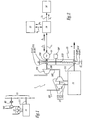
- Figure 1 shows the general layout of a mechanical turbo compound system which comprises an internal combustion engine 11 equipped with a turbo charger 17.
- a turbine 192 is installed in an exhaust line of engine 11 and coupled, via a hydraulic torque converter 20 and a gear train 13, to the crankshaft 111 of engine 11. Power transmission within converter 20 takes place by friction, which induces high energy losses.
- the speed ratio of the output shaft 193 of turbine 192 and crankshaft 111 is fixed, so that it is not possible to keep items 192 and 111 at rotation speeds corresponding to optimized working conditions for each of them.
- EP 420705 A discloses the features of the preamble of claim 1.
- This invention aims at proposing a new power unit for an automotive vehicle which enables an efficient energy recovery including when the automotive vehicles run with a stabilized speed, with a great versatility of the conditions of use of the power unit.
- the invention concerns a power unit for an automotive vehicle, this unit including an internal combustion engine, an electric machine electrically connected to electrical power storage means, a turbocharger comprising a first turbine located in an exhaust line of the engine and a second turbine located in an exhaust line of the engine and drivingly connected to the electric machine.
- This power unit is characterized in that it further includes a power transmission set having a first input/output connected to the second turbine and a second input/output connected to a crankshaft of the internal combustion engine, whereas the power transmission set has an adjustable speed reduction ratio between its first and second inputs/outputs.
- the invention energy recovery takes place via the second turbine and the associated power transmission set, whose reduction ratio can be adjusted to optimize the working conditions of both the second turbine and the crankshaft.
- the power transmission set does not transfer energy by friction, unlike a hydraulic torque converter, which implies that energy losses can be low.
- the recovered energy can be used either electrically or mechanically, depending on the actual setting of the power transmission set.
- the energy recovered by the second turbine can be directed towards the electric machine and/or towards the crankshaft of the internal combustion engine.
- such a power unit might incorporate one or several of the following features:
- the invention also concerns an automotive vehicle, in particular a truck, which includes a power unit as mentioned here above.
- a vehicle is more efficient to run than known HEVs.
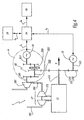
- the power unit 1 represented on figure 2 belongs to a truck and comprises a Diesel internal combustion engine 11 whose crankshaft 111 is supposed to transmit, to a non represented transmission assembly of an automotive vehicle, a torque T.
- Engine 11 is also provided with a turbocharger 17 which comprises a compressor 171 and a turbine 172 coupled to the compressor in order to drive it.
- Compressor 171 and turbine 172 have a common shaft 173, so that they rotate together.
- Compressor 171 is installed in an inlet or feeding line 181 of engine 11 whereas turbine 172 is installed in an exhaust line 182 of engine 11.
- a second turbine 192 is installed within line 182, downstream of turbine 172, so that it is driven by the exhaust gases exiting engine 11, similarly to turbine 172. If engine 11 has several exhaust lines, turbine 182 can be installed in an exhaust line different from the one of turbine 172.
- Turbine 192 is coupled by its output shaft 193 to a continuously variable transmission set or CVT set 21 having an adjustable speed reduction ratio, possibly through a speed reduction gear.
- CVT set 21 comprises a first bi-conical pulley 211 made of two parts 211A and 211B having each a frustro-conical shape.
- a first part 211A of pulley 211 is fast in rotation with, shaft 193.
- the second part 211 B of pulley 211 is connected to, that is fast in rotation with, a shaft 193' aligned with shaft 193.
- Shafts 193 and 193' are fast in rotation so that items 192, 193, 193', 211A and 211B rotate together.
- Shafts 193 and 193' can be built as one single part.
- Control means 197 are provided to adjust the distance d between parts 211A and 211B in a direction parallel to shafts 193 and 193'.
- CVT 21 also includes a second bi-conical pulley 212 fast in rotation with shaft 111, possibly through a reduction gear, and made of two parts 212A and 212B whose distance d' can also be adjusted by control means 197.
- a belt 213 runs between pulleys 211 and 212. Thanks to control means 197, the speed reduction ratio between the rotation speed of pulleys 211 and 212 can be adjusted by varying distances d and d'.
- Parts 211A, 211B, 212A and 212B are moved with respect to each other in such a way that belt 213 has a substantially constant tension.
- CVT speed ratio between its two pulleys 211 and 212 can be adjusted in such a way that the rotation speeds of shaft 193 and crankshaft 111 correspond to optimized working conditions of turbine 192 and engine 11.
- An electric machine 31 is also coupled to pulley 211, namely to part 211 B, via shaft 193'.
- CVT also allows to adjust the rotation speed of machine 31 with respect to the rotation speed of crankshaft 111.
- Shaft 193' forms the central shaft of machine 31 which rotates at the same speed as turbine 192. If, according to a non represented alternative embodiment, a reductor is installed between items 192 and 31, machine 31 runs at a speed which is proportional to and depends on the rotational speed of turbine 192.
- Electric machine 31 is connected by a first electric line L 1 to a power control unit 14 which is piloted by a central non represented main control unit of the truck.
- Unit 14 is connected by an electric line L 2 to electrical power storage means which, in this example, are formed of a battery set 15.
- Unit 14 is also connected by a third electrical line L 3 to several electrical loads 16 such as a lighting system of the vehicle, an electrical or electronical control system, some motors for various appliances.
- Power in lines L 1 and L 2 can go in both directions that is, respectively, from machine 31 to unit 14 and reverse, and from unit 14 to set 15 and reverse. Power in line L 3 can go only from unit 14 to loads 16.
- Machine 31 can work as a motor or as a generator. When it is driven by shaft 193' fast with pulley 211, machine 31 works as a generator and can provide power unit 14 with electrical power, as shown by arrow A 1 . Unit 14 can distribute the power coming from machine 31 between electrical loads 16 and battery set 15, as shown by arrows A 2 and A 3 . Therefore, thanks to CVT set.21, power recovered by turbine 192 is transmitted partly to crankshaft 111, as mechanical power, and partly to power unit 14, as electrical power.
- Electric machine 31 can also work as a motor when it is provided with electrical power, as shown by arrow A 4 . Under such circumstances, some extra power is delivered by machine 31 to pulley 211, this power being transferred to crankshaft 111 via belt 213 and pulley 212.
- CVT 21 enables power transmission, with a variable ratio between turbine 192 and machine 31 on the one hand, and shaft 111, on the other hand. Each of these elements is connected to one input/output of CVT 21.
- a first input/output is formed by pulley 211. Items 192 and 31 are connected to this input/output.
- Crankshaft 111 is connected to pulley 212 which forms the second input/output of CVT 21.
- Mechanical power coming from turbine 192 or shaft 111 can be recovered, as electrical power, by machine 31. Besides, electrical power can be transformed, by machine 31 working as a motor, into mechanical power which can be transferred mainly to crankshaft 111.
- a part of the mechanical power transferred by electrical machine 31 working as a motor to shaft 193' can also be directed to turbine 192 which can be used to accelerate exhaust gases within exhaust line 182 in order to enhance air feeding to engine 11 through turbocharger 17, since the depression created in line 182 drives turbine 172 and compressor 171.
- Crankshaft 111 is provided with a first pinion 131 which meshes with a second pinion 132 mounted on the shaft 121 of another electric machine 12 which can work as a motor or as a generator.
- Pinions 131 and 132 constitute together an example of a gear train 13 between shafts 111 and 121 where machine 12 and shaft 111 are mechanically coupled by a transmission with fixed speed ratio.
- gear train 13 instead of gear train 13, other types of gear trains could be used, such as an epicyclic gear.
- Power transmission between shafts 111 and 121 can also take place via belts and pulleys or pinions, as long as the ratio of the speeds of these shafts is constant.
- shafts 111 and 121 might be formed by the same part.
- Machine 12 is then said to be integrated into engine 11.
- Machine 12 is electrically connected to power unit 14 via an electric line L 4 .
- unit 1 works as follows: when the vehicle is breaking, electric machine 12 works as a generator and provides unit 14 with electric power, as shown by arrow A 5 .
- Unit 14 can distribute the power between electrical loads 16 and battery set 15, as shown by arrows A 2 and A 3 .
- electric machine 12 can be used as a motor to assist engine 11, thanks to the energy provided by the battery set 15 through control unit 14, as shown by arrow A 6 .
- Power may also go directly from one machine 12 or 31 to the other, via unit 14, without being stored in battery set 15.
- crankshaft 111 by a proper control of unit 14, power can be added to crankshaft 111 by either one or both machines 12 and 31.
- a part of the mechanical power transferred to crankshaft 111 by engine 11 can be transformed into electrical power by either one or both machines 12 and 31.
- Unit 14 allows to direct a part only or the totality of the power coming from electric machine 31 towards electric machine 12, which corresponds to a great flexibility of the invention.
- machine 31 can be used as a motor, on the basis of power provided by battery set 15 through control unit 14 as shown by arrow A 6 .
- the mechanical power transferred to CVT set 21 can be used to drive shaft 111 or turbine 192 as in the embodiment of figure 2 .
- the power unit 1 of this embodiment comprises an internal combustion engine 11, a first electric machine 12, a second electric machine 31, a turbocharger 17 which comprises, amongst others, a first turbine 172 located in an exhaust line 182 of engine 11.
- a second turbine 192 is also located in exhaust line 182 and can drive electric machine 31.
- a power control unit 14 is electrically connected to a battery set 15, electric loads 16 and machines 12 and 31; through lines L 1 , L 2 , L 3 and L 4 as mentioned for the second embodiment.
- An epicyclic gear train 22 is installed between the output shaft 193 of turbine 192 and the central shaft 311 of electric machine 31.
- Gear train 22 forms a triple input/output power transmission set between items 192, 31 and 111.
- shaft 193 is provided with a pinion 194 whereas shaft 311 is provided with another pinion 312.
- One shaft 221 of gear 22 is provided with a pinion 222 which meshes with pinion 194, whereas another shaft 223 of gear 22 is provided with another pinion 224 which meshes with pinion 312.
- Shaft 221 is fast with the sun 225 of gear 22, whereas shaft 223 is fast with the outer ring 226 of gear 22.
- the satellite-carrier 227 of gear 22 meshes with a pinion 228 which meshes with pinion 131 fast with crankshaft 111 of engine 11.
- gear train 22 As shown on figure 5 , three fixed speed ratio transmission gears G 1 , G 2 and G 3 can be identified. These gears are input/outputs for gear train 22. Gear G 1 transmits torque between shafts 193 and 221, via pinions 194 and 222. Gear G 2 transmits torque between carrier 227 and shaft 111, via pinion 228. Gear G 3 transmits torque between shafts 223 and 311, via pinions 224 and 212.
- Power transiting through gear 22 when turbine 192 drives machine 21 can be partly derivated by gear 22 to directly drive shaft 111, which increases the total torque T available on shaft 111.
- machine 31 can work as a generator or as a motor when it is driven by turbine 192.
- Gear train 22 can be designed so that the rotation speed of shaft 311 remains within a predetermined range, including zero, under normal working conditions of motor 11.
- Hybrid regenerative mode that is when energy is recovered by machine 12 during breaking of crankshaft 111, a passive torque is applied by machine 12 which works as a generator and delivers electrical power to battery set 15 through unit 14. No torque is applied by machine 31 to turbine 192 and crankshaft 111.
- the powers respectively delivered by engine 11, machine 12 and machine 31 can add up to constitute the total power obtainable on shaft 111.
- Power transmitted from turbine 192 to shaft 111 follows both an electrical way, via machines 31 and 12, and a mechanical way, via gear train 22 and transmission gear G 3 .
- Machine 31 can also be used as a motor.
- shaft 193 may be braked or blocked, which induces that at least a part of the power generated by machine 31 goes to crankshaft 111 through transmission gears G 2 and G 3 and gear train 22.
- power control unit 14 can allow to easily control electric machines 12 and 31 in order to obtain the desired total power on crankshaft 111.
- machine 31 can be used, as a motor or as a generator, to adjust, via gear train 22, the rotational speeds of shafts 193 and 111.
- the external ring 226 of an epicyclic gear 22 can be used to transmit power to crankshaft 111.
- the satellite-carrier 227 of an epicyclic gear 22 can be used for this purpose.
- the satellite carrier 227 of epicyclic gear train 22 can be coupled to shaft 193.
- An additional electric machine 41 is installed between turbine 192 and gear train 22.
- Machine 41 is coupled to shaft 193 and to a shaft 198 fast with a pinion 194 similar to the pinion 194 of the third embodiment.
- Machine 41 can work as a motor or as a generator, depending on the working conditions of unit 1.
- Machine 41 is connected by an electrical line L 5 to power unit 14. Electrical power can go from machine 41 working as a generator to unit 14, as shown by arrow A 7 , and from unit 14 to machine 41 working as a motor, as shown by arrow A 8 .
- Machine 41 allows to recover electrical power directly from turbine 192. When it works as a motor, machine 41 can drive directly turbine 192 and/or crankshaft 111 via gear train 22
- An electric machine 51 is installed on the shaft 173 of turbo charger 17, between its compressor 171 and its turbine 172.
- Machine 51 is mechanically coupled to items 171 and 172.
- Machine 51 is connected to power control unit 14 via an electric line L 6 and power can go from machine 51 to unit 14, as shown by arrow A 9 , and from unit 14 to machine 51, as shown by arrow A 10 .
- Electric machine 51 can work as a generator in order to recover mechanical energy from turbine 172 and to transmit it to power control unit 14. This electrical power can then be distributed between battery set 15, electrical loads 16 and/or machines 12 and 31.
- Electrical machine 51 can also work as a motor to drive compressor 171 in order to enhance air feeding to engine 11.
- transmission gears similar to the ones G 1 , G 2 and G 3 of figure 5 can be defined, with the same function.
- Turbine 192 is connected to gear G 1 .
- crankshaft 111 is connected to gear G 2 and machine 31 is connected to gear G 3 .
- electric machine 12 is preferably the main source of power addition to engine 11. It is more powerful than machine 31.
- machine 12 can have a nominal power between 100 and 150 kW, whereas machine 31 has a nominal power between 5 and 50 kW.
- machine 12 can be an alternator/state starter machine, which is a relatively low power hybrid machine.
- machine 12 is optional in the embodiments of figures 4 to 12 .
- only one electric machine could be used with an epicyclic gear train, according to an approach similar to the one of the embodiment of figure 2 .
- epicyclic gear train 22 instead of epicyclic gear train 22, one can use another type of triple input/output transmission set, e.g. a classical automotive differential gear.
- machine 31 can be used as a generator in order to load battery set 15 when the speed of the engine increases or is above a limit value.
- the torque generated by this electric machine working as a motor in some conditions can be used by this machine in order to improve the working conditions of the engine, either by acting on exhaust line 182, as in the first embodiment, or by acting directly on the crankshaft 111 of the engine, as in the second to seventh embodiments.
Landscapes
- Engineering & Computer Science (AREA)
- Mechanical Engineering (AREA)
- Combustion & Propulsion (AREA)
- Transportation (AREA)
- Chemical & Material Sciences (AREA)
- Power Engineering (AREA)
- General Engineering & Computer Science (AREA)
- Automation & Control Theory (AREA)
- Supercharger (AREA)
- Arrangement Or Mounting Of Propulsion Units For Vehicles (AREA)
- Retarders (AREA)
- Hybrid Electric Vehicles (AREA)
- Control Of Vehicle Engines Or Engines For Specific Uses (AREA)
Abstract
Description
- This invention concerns a power unit for an automotive vehicle and an automotive vehicle including such a power unit.
- The reduction of fuel consumption of automotive vehicles, in particular trucks, is a major issue for the sustainability of road transport and is a vital element for the competitiveness of trucks manufacturers. A majority of trucks is fitted with a turbocharged diesel engine that runs, on the one hand, the driving wheels through a transmission and, on the other hand, auxiliary equipments, such as a lighting system or a window actuator. Some of these auxiliary equipments are usually fed by an electrical network whose electrical power is produced by an alternator driven by the internal combustion engine of the truck. In order to obtain fuel economies when running an automotive vehicle, one can consider recovering energy which would otherwise be wasted. Known techniques can limit a fraction of the energy losses. This concerns hybrid systems where braking energy is recovered through electrical power storage. In so-called "hybrid electric vehicles" or "HEVs", one uses a combination of an internal combustion engine with one or several electrical machines and some storage means such as batteries.
-
EP-A-0 366 536 teaches the use of a turbine located in an exhaust line of an internal combustion engine, downstream of a turbocharger, in order to drive an electrical generator which loads a battery. A mechanical pump is also driven by this turbine, in order to load a reservoir of fluid under pressure. No power can be added to the power delivered by the engine. -
Figure 1 shows the general layout of a mechanical turbo compound system which comprises aninternal combustion engine 11 equipped with aturbo charger 17. Aturbine 192 is installed in an exhaust line ofengine 11 and coupled, via ahydraulic torque converter 20 and agear train 13, to thecrankshaft 111 ofengine 11. Power transmission withinconverter 20 takes place by friction, which induces high energy losses. Moreover, the speed ratio of theoutput shaft 193 ofturbine 192 andcrankshaft 111 is fixed, so that it is not possible to keepitems -
EP 420705 A claim 1. - This invention aims at proposing a new power unit for an automotive vehicle which enables an efficient energy recovery including when the automotive vehicles run with a stabilized speed, with a great versatility of the conditions of use of the power unit.
- The invention concerns a power unit for an automotive vehicle, this unit including an internal combustion engine, an electric machine electrically connected to electrical power storage means, a turbocharger comprising a first turbine located in an exhaust line of the engine and a second turbine located in an exhaust line of the engine and drivingly connected to the electric machine. This power unit is characterized in that it further includes a power transmission set having a first input/output connected to the second turbine and a second input/output connected to a crankshaft of the internal combustion engine, whereas the power transmission set has an adjustable speed reduction ratio between its first and second inputs/outputs.
- Thanks to the invention, energy recovery takes place via the second turbine and the associated power transmission set, whose reduction ratio can be adjusted to optimize the working conditions of both the second turbine and the crankshaft. The power transmission set does not transfer energy by friction, unlike a hydraulic torque converter, which implies that energy losses can be low. The recovered energy can be used either electrically or mechanically, depending on the actual setting of the power transmission set. In particular, the energy recovered by the second turbine can be directed towards the electric machine and/or towards the crankshaft of the internal combustion engine.
- According to further aspects of the invention, such a power unit might incorporate one or several of the following features:
- According to a first embodiment of the invention, the transmission set comprises a pulley and a belt type continuously variable transmission set (CVT set). The continuously variable power transmission set includes advantageously two bi-conical pulleys connected by a belt, whereas the second turbine and the electric machine are connected to two parts of the same pulley whose relative position can be modified in order to adjust the speed reduction ratio of said transmission set and whereas the crankshaft is connected to the other pulley.
- According to another embodiment of the invention, the transmission set is a triple input/output power transmission set having its third input/output connected to the electric machine. Such a transmission set comprises advantageously an epicyclic gear train. According to several embodiments of the invention, the part of the gear train which is coupled to the crankshaft of the engine is its sun, its ring or its satellite-carrier. Similarly, the part of the gear train which is coupled to the turbine can be its sun, its ring or its satellite carrier.
- The electric machine can work as a generator or as a motor, depending on the working conditions of the power unit.
- The unit can include another electric machine electrically connected to the electrical power storage means and coupled to the crankshaft independently of the triple input/output transmission set.
- The unit can include another electric machine electrically connected to the electrical power storage means and mechanically coupled to the second turbine and to the first input/output of the power transmission set.
- The unit can include another electric machine electrically connected to the electrical power storage means and mechanically coupled to a turbine and a compressor of the turbocharger.
- The electric machines are connected to the electrical power storage means via a power control unit which is also connected to electrical loads on the vehicle.
- Both electric machines can work as a generator or as a motor, depending on the working conditions of the power unit.
- The other electric machine can deliver, when it works as a motor, a maximum power which is higher than the maximum power which can be delivered by the electric machine connected to the second input/output of the transmission set. In other words, the other electric machine has a higher power capacity than the electric machine connected to the transmission set.
- The second turbine is located in the same exhaust line and downstream of the first turbine.
- The invention also concerns an automotive vehicle, in particular a truck, which includes a power unit as mentioned here above. Such a vehicle is more efficient to run than known HEVs.
- The invention will now be explained in correspondence with the annexed figures and as an illustrative example, without restricting the object of the invention. In the annexed figures:
-
figure 1 is a schematic representation of a power unit of the prior art, -
figure 2 is a view similar tofigure 1 , at a larger scale, for a power unit according to a first embodiment of the invention, -
figure 3 is a view similar tofigure 2 for a power unit according to a second embodiment of the invention, -
figure 4 is a view similar tofigure 2 for a power unit according to a third embodiment of the invention, -
figure 5 is an enlarged view of detail V onfigure 4 , -
figure 6 is a view similar tofigure 5 for a power unit according to a fourth embodiment of the invention, -
figure 7 is a view similar tofigure 5 for a power unit according to a fifth embodiment of the invention, -
figure 8 is a view similar tofigure 5 for a power unit according to a sixth embodiment of the invention, -
figure 9 is a view similar tofigure 5 for a power unit according to a seventh embodiment of the invention, -
figure 10 is a view similar tofigure 5 for a power unit according to an eighth embodiment of the invention, -
figure 11 is a view similar tofigure 2 for a power unit according to a ninth embodiment, and -
figure 12 is a view similar tofigure 2 for a power unit according to a tenth embodiment. - The
power unit 1 represented onfigure 2 belongs to a truck and comprises a Dieselinternal combustion engine 11 whosecrankshaft 111 is supposed to transmit, to a non represented transmission assembly of an automotive vehicle, a torque T. -
Engine 11 is also provided with aturbocharger 17 which comprises acompressor 171 and aturbine 172 coupled to the compressor in order to drive it.Compressor 171 andturbine 172 have acommon shaft 173, so that they rotate together.Compressor 171 is installed in an inlet orfeeding line 181 ofengine 11 whereasturbine 172 is installed in anexhaust line 182 ofengine 11. - A
second turbine 192 is installed withinline 182, downstream ofturbine 172, so that it is driven by the exhaustgases exiting engine 11, similarly toturbine 172. Ifengine 11 has several exhaust lines,turbine 182 can be installed in an exhaust line different from the one ofturbine 172. -
Turbine 192 is coupled by itsoutput shaft 193 to a continuously variable transmission set or CVT set 21 having an adjustable speed reduction ratio, possibly through a speed reduction gear. CVT set 21 comprises a firstbi-conical pulley 211 made of twoparts first part 211A ofpulley 211 is fast in rotation with,shaft 193. Thesecond part 211 B ofpulley 211 is connected to, that is fast in rotation with, a shaft 193' aligned withshaft 193.Shafts 193 and 193' are fast in rotation so thatitems Shafts 193 and 193' can be built as one single part. Control means 197 are provided to adjust the distance d betweenparts shafts 193 and 193'.CVT 21 also includes a secondbi-conical pulley 212 fast in rotation withshaft 111, possibly through a reduction gear, and made of twoparts belt 213 runs betweenpulleys means 197, the speed reduction ratio between the rotation speed ofpulleys -
Parts belt 213 has a substantially constant tension. - Thanks to control
means 197, CVT speed ratio between its twopulleys shaft 193 andcrankshaft 111 correspond to optimized working conditions ofturbine 192 andengine 11. - An
electric machine 31 is also coupled topulley 211, namely topart 211 B, via shaft 193'. CVT also allows to adjust the rotation speed ofmachine 31 with respect to the rotation speed ofcrankshaft 111. Shaft 193' forms the central shaft ofmachine 31 which rotates at the same speed asturbine 192. If, according to a non represented alternative embodiment, a reductor is installed betweenitems machine 31 runs at a speed which is proportional to and depends on the rotational speed ofturbine 192. -
Electric machine 31 is connected by a first electric line L1 to apower control unit 14 which is piloted by a central non represented main control unit of the truck.Unit 14 is connected by an electric line L2 to electrical power storage means which, in this example, are formed of abattery set 15.Unit 14 is also connected by a third electrical line L3 to severalelectrical loads 16 such as a lighting system of the vehicle, an electrical or electronical control system, some motors for various appliances. Power in lines L1 and L2 can go in both directions that is, respectively, frommachine 31 tounit 14 and reverse, and fromunit 14 to set 15 and reverse. Power in line L3 can go only fromunit 14 to loads 16. - When
engine 11 runs above a given speed, exhaust gazes inline 182 are fast enough to driveturbine 192 which then drivespulley 211. Whenpulley 211 is driven byshaft 193, CVT set 21 forwards some power toshaft 111 viabelt 213 andpulley 212. -
Machine 31 can work as a motor or as a generator. When it is driven by shaft 193' fast withpulley 211,machine 31 works as a generator and can providepower unit 14 with electrical power, as shown by arrow A1. Unit 14 can distribute the power coming frommachine 31 betweenelectrical loads 16 and battery set 15, as shown by arrows A2 and A3. Therefore, thanks to CVT set.21, power recovered byturbine 192 is transmitted partly tocrankshaft 111, as mechanical power, and partly topower unit 14, as electrical power. - One should note that power recovery can take place via
machine 31 even when the truck does not brake, in particular when it runs with a stabilized speed sinceturbine 192 is driven by exhaust gases under these conditions. -
Electric machine 31 can also work as a motor when it is provided with electrical power, as shown by arrow A4. Under such circumstances, some extra power is delivered bymachine 31 topulley 211, this power being transferred tocrankshaft 111 viabelt 213 andpulley 212. -
CVT 21 enables power transmission, with a variable ratio betweenturbine 192 andmachine 31 on the one hand, andshaft 111, on the other hand. Each of these elements is connected to one input/output ofCVT 21. A first input/output is formed bypulley 211.Items Crankshaft 111 is connected topulley 212 which forms the second input/output ofCVT 21. Mechanical power coming fromturbine 192 orshaft 111 can be recovered, as electrical power, bymachine 31. Besides, electrical power can be transformed, bymachine 31 working as a motor, into mechanical power which can be transferred mainly tocrankshaft 111. - Moreover, in some working conditions of
unit 1 and depending on the setting of CVT set 21, a part of the mechanical power transferred byelectrical machine 31 working as a motor to shaft 193' can also be directed toturbine 192 which can be used to accelerate exhaust gases withinexhaust line 182 in order to enhance air feeding toengine 11 throughturbocharger 17, since the depression created inline 182 drivesturbine 172 andcompressor 171. - Therefore, thanks to the invention, a great versatility of the power transmission within
power unit 1 can be obtained. - In the embodiment of
figure 3 , the same elements as infigure 2 bear the same references.Crankshaft 111 is provided with afirst pinion 131 which meshes with asecond pinion 132 mounted on theshaft 121 of anotherelectric machine 12 which can work as a motor or as a generator.Pinions gear train 13 betweenshafts machine 12 andshaft 111 are mechanically coupled by a transmission with fixed speed ratio. Instead ofgear train 13, other types of gear trains could be used, such as an epicyclic gear. Power transmission betweenshafts - According to an alternative embodiment of the invention,
shafts Machine 12 is then said to be integrated intoengine 11. -
Machine 12 is electrically connected topower unit 14 via an electric line L4. - In this embodiment,
unit 1 works as follows: when the vehicle is breaking,electric machine 12 works as a generator and providesunit 14 with electric power, as shown by arrow A5. Unit 14 can distribute the power betweenelectrical loads 16 and battery set 15, as shown by arrows A2 and A3. When the vehicle is being accelerated,electric machine 12 can be used as a motor to assistengine 11, thanks to the energy provided by the battery set 15 throughcontrol unit 14, as shown by arrow A6. - On the other hand, as soon as
turbine 192 rotates, some extra power can be transferred tomachine 31 and/orshaft 111, as explained for the embodiment offigure 2 . - Power may also go directly from one
machine unit 14, without being stored in battery set 15. - The torque delivered by
machine 12, when it works as a motor, depends on the rotation speeds ofengine 11. This torque is quite constant at low rotation speed of the engine and then decreases. - Therefore, by a proper control of
unit 14, power can be added tocrankshaft 111 by either one or bothmachines crankshaft 111 byengine 11 can be transformed into electrical power by either one or bothmachines -
Unit 14 allows to direct a part only or the totality of the power coming fromelectric machine 31 towardselectric machine 12, which corresponds to a great flexibility of the invention. - In some other working conditions of
unit 1,machine 31 can be used as a motor, on the basis of power provided by battery set 15 throughcontrol unit 14 as shown by arrow A6. The mechanical power transferred to CVT set 21 can be used to driveshaft 111 orturbine 192 as in the embodiment offigure 2 . - In the third embodiment of the invention represented on
figures 4 and5 , the same elements as in the second embodiment bear the same references. Thepower unit 1 of this embodiment comprises aninternal combustion engine 11, a firstelectric machine 12, a secondelectric machine 31, aturbocharger 17 which comprises, amongst others, afirst turbine 172 located in anexhaust line 182 ofengine 11. Asecond turbine 192 is also located inexhaust line 182 and can driveelectric machine 31. Apower control unit 14 is electrically connected to a battery set 15,electric loads 16 andmachines - An
epicyclic gear train 22 is installed between theoutput shaft 193 ofturbine 192 and thecentral shaft 311 ofelectric machine 31.Gear train 22 forms a triple input/output power transmission set betweenitems - As shown in detail on
figure 5 ,shaft 193 is provided with apinion 194 whereasshaft 311 is provided with anotherpinion 312. Oneshaft 221 ofgear 22 is provided with apinion 222 which meshes withpinion 194, whereas anothershaft 223 ofgear 22 is provided with anotherpinion 224 which meshes withpinion 312.Shaft 221 is fast with thesun 225 ofgear 22, whereasshaft 223 is fast with theouter ring 226 ofgear 22. The satellite-carrier 227 ofgear 22 meshes with apinion 228 which meshes withpinion 131 fast withcrankshaft 111 ofengine 11. - As shown on
figure 5 , three fixed speed ratio transmission gears G1, G2 and G3 can be identified. These gears are input/outputs forgear train 22. Gear G1 transmits torque betweenshafts pinions carrier 227 andshaft 111, viapinion 228. Gear G3 transmits torque betweenshafts pinions - Instead of pinions, one can use, for transmission gears G1, G2 and G3, some other type of transmission sets, for example with pulleys and belts.
- Power transiting through
gear 22 whenturbine 192drives machine 21 can be partly derivated bygear 22 to directly driveshaft 111, which increases the total torque T available onshaft 111. - Depending on the relative speed of
shafts gear train 22,machine 31 can work as a generator or as a motor when it is driven byturbine 192. - The rotation speed and direction of
machine 31 depend on the rotation speeds ofshafts Gear train 22 can be designed so that the rotation speed ofshaft 311 remains within a predetermined range, including zero, under normal working conditions ofmotor 11. - In "hybrid" regenerative mode, that is when energy is recovered by
machine 12 during breaking ofcrankshaft 111, a passive torque is applied bymachine 12 which works as a generator and delivers electrical power to battery set 15 throughunit 14. No torque is applied bymachine 31 toturbine 192 andcrankshaft 111. - In "compound" mode, when exhaust gazes drive
turbine 192,machine 31 applies a torque onshaft 223 ofgear 22, so that a passive torque is applied toshaft 193. Depending on its rotation direction,machine 31 produces or uses electrical power going to or coming fromunit 14. In "compound" mode, the rotation speed ofmachine 31 is fixed by the respective speeds ofcrankshaft 111 andturbine 192, depending on the design ofgear train 22 and transmission gears G1, G2 and G3. Whenmachine 31 applies a passive or braking torque ongear train 22, it is transferred toshaft 193, so that the torque is applied tocrankshaft 111. Depending on its direction of rotation,machine 31 is a generator or a motor and mechanical power is transmitted to or derived fromcrankshaft 111 viagear train 22. Maximum torque transmission frommachine 31 tocrankshaft 111 takes place when engine speed is above a reference speed. - The powers respectively delivered by
engine 11,machine 12 andmachine 31 can add up to constitute the total power obtainable onshaft 111. Power transmitted fromturbine 192 toshaft 111 follows both an electrical way, viamachines gear train 22 and transmission gear G3. -
Machine 31 can also be used as a motor. In such a circumstance,shaft 193 may be braked or blocked, which induces that at least a part of the power generated bymachine 31 goes tocrankshaft 111 through transmission gears G2 and G3 andgear train 22. - Here again,
power control unit 14 can allow to easily controlelectric machines crankshaft 111. - As a summary, by a proper control of
machine 31 viaunit 14, one can adjust the speed reduction ratio betweenshafts turbine 192 andengine 11 work at an optimal rotational speed. In other words,machine 31 can be used, as a motor or as a generator, to adjust, viagear train 22, the rotational speeds ofshafts - As shown on
figures 6 and8 , theexternal ring 226 of anepicyclic gear 22 can be used to transmit power tocrankshaft 111. As shown onfigures 7 and8 , the satellite-carrier 227 of anepicyclic gear 22 can be used for this purpose. As shown onfigures 8 and 10 , thesatellite carrier 227 ofepicyclic gear train 22 can be coupled toshaft 193. As shown onfigures 7 and9 , one can couple theoutside ring 226 ofepicyclic gear 22 toshaft 193. - In the ninth embodiment of the invention represented on
figure 11 , the same elements as in the third embodiment bear the same references. An additionalelectric machine 41 is installed betweenturbine 192 andgear train 22.Machine 41 is coupled toshaft 193 and to ashaft 198 fast with apinion 194 similar to thepinion 194 of the third embodiment.Machine 41 can work as a motor or as a generator, depending on the working conditions ofunit 1.Machine 41 is connected by an electrical line L5 topower unit 14. Electrical power can go frommachine 41 working as a generator tounit 14, as shown by arrow A7, and fromunit 14 tomachine 41 working as a motor, as shown by arrow A8. Machine 41 allows to recover electrical power directly fromturbine 192. When it works as a motor,machine 41 can drive directlyturbine 192 and/orcrankshaft 111 viagear train 22 - In the tenth embodiment of the invention represented on
figure 12 , the same elements as in the third embodiment bear the same references. An electric machine 51 is installed on theshaft 173 ofturbo charger 17, between itscompressor 171 and itsturbine 172. Machine 51 is mechanically coupled toitems power control unit 14 via an electric line L6 and power can go from machine 51 tounit 14, as shown by arrow A9, and fromunit 14 to machine 51, as shown by arrow A10. Electric machine 51 can work as a generator in order to recover mechanical energy fromturbine 172 and to transmit it topower control unit 14. This electrical power can then be distributed between battery set 15,electrical loads 16 and/ormachines compressor 171 in order to enhance air feeding toengine 11. - In the embodiments of
figures 6 to 12 , transmission gears similar to the ones G1, G2 and G3 offigure 5 can be defined, with the same function.Turbine 192 is connected to gear G1. crankshaft 111 is connected to gear G2 andmachine 31 is connected to gear G3. - In the embodiments of
figures 3 to 12 ,electric machine 12 is preferably the main source of power addition toengine 11. It is more powerful thanmachine 31. For example,machine 12 can have a nominal power between 100 and 150 kW, whereasmachine 31 has a nominal power between 5 and 50 kW. In the embodiments offigures 3 to 12 ,machine 12 can be an alternator/state starter machine, which is a relatively low power hybrid machine. - However,
machine 12 is optional in the embodiments offigures 4 to 12 . In other words, only one electric machine could be used with an epicyclic gear train, according to an approach similar to the one of the embodiment offigure 2 . - Instead of
epicyclic gear train 22, one can use another type of triple input/output transmission set, e.g. a classical automotive differential gear. - The technical features of the embodiments described here-above can be combined. In particular, electrical machines similar to
machines 41 and 51 can be added to the embodiments where they are not represented, including the ones offigures 2 and3 . - In all the embodiments of the invention, depending on the working conditions of
engine 11,machine 31 can be used as a generator in order to load battery set 15 when the speed of the engine increases or is above a limit value. The torque generated by this electric machine working as a motor in some conditions can be used by this machine in order to improve the working conditions of the engine, either by acting onexhaust line 182, as in the first embodiment, or by acting directly on thecrankshaft 111 of the engine, as in the second to seventh embodiments. -
- 1
- power unit
- 11
- internal combustion engine
111 crankshaft
112 pinion - 12
- electric machine
121 shaft - 13
- gear train
131 pinion
132 pinion - 14
- control unit
- 15
- battery set
- 16
- electrical loads
- 17
- turbocharger
171 compressor
172 turbine
173 shaft
181 inlet line
182 exhaust line
192 turbine
193 output shaft
193' shaft
194 pinion
197 control means
198 shaft - 20
- hydraulic torque converter
- 21
- continuously variable transmission set (CVT set)
211 pulley
211A first part
211 B second part
212 pulley
212A first part
212B second part
213 belt - 22
- epicyclic gear train
221 shaft
222 pinion
223 shaft
224 pinion
225 sun
226 ring
227 satellite-carrier
228 pinion - 31
- electric machine
311 shaft
312 shaft - 41
- electric machine
- 51
- electric machine
- A1
- arrow
- A2
- arrow
- A3
- arrow
- A4
- arrow
- A5
- arrow
- A6
- arrow
- A7
- arrow
- A8
- arrow
- A9
- arrow
- A10
- arrow
- d
- distance between 211A and 211B
- d'
- distance between 211A and 211B
- L1
- electric line
- L2
- electric line
- L3
- electric line
- L4
- electric line
- L5
- electric line
- L6
- electric line
- G1
- transmission gear
- G2
- transmission gear
- G3
- transmission gear
- T
- torque
Claims (15)
- A power unit for an automotive vehicle said unit comprising:- an internal combustion engine (11),- an electric machine (31) electrically connected to electrical power storage means (15),- a turbocharger (17) comprising a first turbine (172) located in an exhaust line (182) of said engine, and- a second turbine (192) located in an exhaust line (182) of said engine, and drivingly connected to said electric machine,- a transmission set (22) having a first input/output (G1) connected to said second turbine (192) and a second input/output (G2) connected to a crankshaft (111) of said internal combustion engine (11)characterized in that said power transmission set (22) has an adjustable speed reduction ratio between said first and second inputs/outputs (G1, G2) and in that said transmission set is a triple input/output transmission set (22) having its third input/output (G3) connected to said electric machine (31).
- Power unit according to claim1, characterized in that said triple input/output transmission set comprises an epicyclic gear train (22).
- Power unit according to claim 2, characterized in that the sun (225) of said gear train (22) is coupled to said crankshaft (111).
- Power unit according to claim 2, characterized in that the ring (226) of said gear train (22) is coupled to said crankshaft (111).
- Power unit according to claim 2, characterized in that the satellite-carrier (227) of said gear train (22) is coupled to said crankshaft (111).
- Power unit according to one of claims 2, 4 and 5, characterized in that the sun (225) of said gear train (22) is coupled to said turbine (192).
- Power unit according to one of claims 2, 3 and 5, characterized in that the ring (226) of said gear train (22) is coupled to said turbine (192).
- Power unit according to one of claims 2, 3 and 4 characterized in that the satellite carrier (227) of said gear train (22) is coupled to said turbine.
- Power unit according to any one of the previous claims, characterized in that said electric machine (31) can work as a generator or as a motor, depending on the working conditions of said power unit (1).
- Power unit according to any one of the previous claims, characterized in that it also includes another electric machine (12) electrically connected to said electrical power storage means (15) and coupled to said crankshaft independently of said triple input/output transmission set (21; 22).
- Power unit according to any one of the previous claims, characterized in that it also includes another electric machine (41) electrically connected to said electrical power storage means (15) and mechanically coupled to said second turbine (192) and to said first input/output (211A; G1) of said transmission set (21; 22).
- Power unit according to any one of the previous claims, characterized in that it also includes another electric machine (51) electrically connected to said electrical power storage means (15) and mechanically coupled to a compressor (171) and to a turbine (172) of said turbo charger (17).
- Power unit according to claim 10 , characterized In that both electric machines (12, 31; 41; 51) can work as a generator or as a motor, depending on the working conditions of said power unit (1).
- Power unit according to claim 10, characterized in that said other electric machine (12) can deliver, when it works as a motor, a maximum power which is higher than the maximum power which can be delivered by said electric machine (31) connected to said third input/output (G3) of said transmission set.
- An automotive vehicle, in particular a truck, including a power unit (1) according to any of the previous claims.
Applications Claiming Priority (1)
| Application Number | Priority Date | Filing Date | Title |
|---|---|---|---|
| PCT/IB2006/004070 WO2008075127A1 (en) | 2006-12-19 | 2006-12-19 | Power unit for an automotive vehicle and vehicle including such a power unit |
Publications (2)
| Publication Number | Publication Date |
|---|---|
| EP2126312A1 EP2126312A1 (en) | 2009-12-02 |
| EP2126312B1 true EP2126312B1 (en) | 2010-12-08 |
Family
ID=38430463
Family Applications (1)
| Application Number | Title | Priority Date | Filing Date |
|---|---|---|---|
| EP06847290A Ceased EP2126312B1 (en) | 2006-12-19 | 2006-12-19 | Power unit for an automotive vehicle and vehicle including such a power unit |
Country Status (7)
| Country | Link |
|---|---|
| US (1) | US8261550B2 (en) |
| EP (1) | EP2126312B1 (en) |
| JP (1) | JP4906925B2 (en) |
| CN (1) | CN101568710B (en) |
| AT (1) | ATE491084T1 (en) |
| DE (1) | DE602006018806D1 (en) |
| WO (1) | WO2008075127A1 (en) |
Families Citing this family (36)
| Publication number | Priority date | Publication date | Assignee | Title |
|---|---|---|---|---|
| DE102005004058B3 (en) * | 2005-01-28 | 2006-05-24 | Voith Turbo Gmbh & Co. Kg | Turbo compound system with cylinder shaft and exhaust gas turbine |
| DE102007017777B4 (en) * | 2007-04-16 | 2009-04-09 | Siemens Ag | Turbocharger arrangement and turbochargeable internal combustion engine |
| TWI340204B (en) * | 2008-03-21 | 2011-04-11 | Ind Tech Res Inst | An improved power generating device with constant output rotation speed |
| US8653677B2 (en) | 2009-01-15 | 2014-02-18 | Volvo Technology Corporation | Electromagnetic, continuously variable transmission power split turbo compound and engine and vehicle comprising such a turbo compound |
| FR2945244B1 (en) * | 2009-05-11 | 2012-12-14 | Peugeot Citroen Automobiles Sa | MOTOR VEHICLE EQUIPPED WITH AN ELECTRIC POWER GENERATING SYSTEM COMPRISING A TURBINE DRIVEN BY A MOVING AIR MASS. |
| EP2438278A4 (en) * | 2009-06-04 | 2013-09-11 | Jonathan J Feinstein | COMBUSTION ENGINE |
| DE102009034510A1 (en) * | 2009-07-24 | 2011-04-14 | Bayerische Motoren Werke Aktiengesellschaft | Vehicle with a supercharged combustion engine and method for operating a vehicle with a supercharged combustion engine |
| JP5016706B2 (en) * | 2009-11-04 | 2012-09-05 | 川崎重工業株式会社 | Aircraft starter generator |
| JP5427110B2 (en) * | 2010-05-25 | 2014-02-26 | 川崎重工業株式会社 | Construction machine and control method thereof |
| EP2585694B8 (en) * | 2010-06-22 | 2015-02-18 | Volvo Lastvagnar AB | A turbo compound transmission and a method for controlling a turbo compound transmission |
| CH704652B1 (en) | 2011-03-15 | 2014-12-31 | Keymount GmbH | Drive unit for the operation of a vehicle. |
| CN103649510B (en) * | 2011-04-21 | 2015-07-22 | 马克卡车公司 | Power system with turbine bypass and method of operating a power system |
| DE102011076093A1 (en) * | 2011-05-19 | 2012-11-22 | Robert Bosch Gmbh | Device and method for using the waste heat of an internal combustion engine |
| WO2013004595A1 (en) * | 2011-07-07 | 2013-01-10 | Kasi Technologies Ab | Hybrid system comprising a supercharging system and method for operation |
| US9884538B2 (en) * | 2012-01-26 | 2018-02-06 | Doosan Infracore Co., Ltd. | Turbo compound system for vehicle |
| ITCO20120002A1 (en) * | 2012-01-27 | 2013-07-28 | Nuovo Pignone Srl | COMPRESSOR SYSTEM FOR NATURAL GAS, METHOD FOR COMPRESSING NATURAL GAS AND PLANT THAT USES THEM |
| US9108628B2 (en) * | 2012-08-31 | 2015-08-18 | GM Global Technology Operations LLC | Turbo compounding hybrid generator powertrain |
| DE102012111847B4 (en) * | 2012-12-05 | 2021-05-20 | Magna Pt B.V. & Co. Kg | Compact gear arrangement for high speeds and drive train with such a compact gear arrangement |
| CN103899409A (en) * | 2012-12-28 | 2014-07-02 | 财团法人金属工业研究发展中心 | Twin-turbine kinetic energy recovery device and vehicle with the device |
| WO2014150265A2 (en) * | 2013-03-15 | 2014-09-25 | Eaton Corporation | Dual ratio drive for variable speed hybrid electric supercharger assembly |
| JP6184741B2 (en) * | 2013-05-15 | 2017-08-23 | 日野自動車株式会社 | Internal combustion engine |
| DE202013004907U1 (en) * | 2013-05-28 | 2013-07-02 | GM Global Technology Operations LLC (n. d. Ges. d. Staates Delaware) | Motor vehicle with a couplable Abwärmenutzanordnung |
| KR101550986B1 (en) * | 2013-11-25 | 2015-09-07 | 현대자동차주식회사 | Hybrid power train for vehicle |
| ES2597163T3 (en) * | 2013-12-20 | 2017-01-16 | Fpt Motorenforschung Ag | Improved turbotraction scheme, particularly in the field of industrial vehicles |
| CN103899366A (en) * | 2014-03-17 | 2014-07-02 | 夏兴旺 | Turbo machinery stepless speed regulator |
| FR3022947B1 (en) * | 2014-06-26 | 2019-05-10 | Valeo Systemes De Controle Moteur | ENGINE SYSTEM WITH LOW PRESSURE RECIRCULATION CIRCUIT FOR BURNED GASES |
| FR3022946B1 (en) * | 2014-06-26 | 2019-06-28 | Valeo Systemes De Controle Moteur | ENGINE SYSTEM WITH BURN GAS RECIRCULATION CIRCUIT |
| US9752496B2 (en) * | 2014-07-21 | 2017-09-05 | Avl Powertrain Engineering, Inc. | Turbocharger with electrically coupled fully variable turbo-compound capability and method of controlling the same |
| US9862262B2 (en) * | 2015-07-30 | 2018-01-09 | Ford Global Technologies, Llc | Hybrid vehicle powertrain |
| US10384525B2 (en) * | 2017-02-02 | 2019-08-20 | FEV Europe GmbH | Systems for power integration of turbines, compressors and hybrid energy devices with internal combustion engines |
| US10570816B2 (en) * | 2017-09-19 | 2020-02-25 | Pratt & Whitney Canada Corp. | Engine coupling arrangement |
| US11732639B2 (en) * | 2019-03-01 | 2023-08-22 | Pratt & Whitney Canada Corp. | Mechanical disconnects for parallel power lanes in hybrid electric propulsion systems |
| US11060449B2 (en) * | 2019-06-04 | 2021-07-13 | Hamilton Sunstrand Corporation | Integrated turbo-compressor with variable gear ratio transmission for internal combustion engine |
| FR3099202B1 (en) * | 2019-07-26 | 2021-07-09 | Safran Aircraft Engines | POWER DISTRIBUTION DEVICE BETWEEN AN ELECTRIC STARTER AND AN ELECTRIC MACHINE TO A SHAFT OF A TURBOMACHINE |
| KR102943046B1 (en) * | 2021-01-04 | 2026-03-23 | 엘지전자 주식회사 | Gas engine heat pump |
| CN112983581A (en) * | 2021-03-27 | 2021-06-18 | 熵零技术逻辑工程院集团股份有限公司 | Fluid mechanism with reverse linkage of guide wheel |
Family Cites Families (15)
| Publication number | Priority date | Publication date | Assignee | Title |
|---|---|---|---|---|
| US3673797A (en) * | 1970-12-08 | 1972-07-04 | Perkins Services Nv | Compound power plant |
| CH658884A5 (en) | 1984-10-01 | 1986-12-15 | Cerac Inst Sa | INTERNAL COMBUSTION ENGINE UNIT. |
| JPH01257722A (en) * | 1988-04-08 | 1989-10-13 | Komatsu Ltd | Power transmission for turbo compound engine |
| JP2526100B2 (en) * | 1988-07-18 | 1996-08-21 | 株式会社 いすゞセラミックス研究所 | Supercharger control device |
| JPH03117632A (en) * | 1989-09-29 | 1991-05-20 | Isuzu Motors Ltd | Composite turbo compound engine |
| GB9016480D0 (en) | 1990-07-27 | 1990-09-12 | F J Wallace & Associates Ltd | Two and four stroke compound diesel engine with cvt drive |
| CN1101397A (en) * | 1993-10-05 | 1995-04-12 | 华中理工大学 | A supplementary combustion turbocharging system |
| GB2317647B (en) * | 1994-01-25 | 1998-09-30 | Komatsu Mfg Co Ltd | A method of controlling a mechanical supercharger |
| JP3315549B2 (en) | 1994-01-25 | 2002-08-19 | 株式会社小松製作所 | Differential drive supercharger and control method thereof |
| EP0755816A3 (en) | 1995-07-28 | 1998-09-02 | Isuzu Ceramics Research Institute Co., Ltd. | Hybrid electric vehicle |
| CN2311615Y (en) * | 1997-04-16 | 1999-03-24 | 张旭 | Waste gas turbine energy recovery apparatus for internal combustion engine |
| US6527658B2 (en) * | 2001-04-02 | 2003-03-04 | General Motors Corporation | Electrically variable transmission with selective input split, compound split, neutral and reverse modes |
| GB2390871B (en) * | 2002-07-16 | 2005-11-16 | Drivetec | Automotive superchargers |
| US7490594B2 (en) * | 2004-08-16 | 2009-02-17 | Woodward Governor Company | Super-turbocharger |
| US7174714B2 (en) * | 2004-12-13 | 2007-02-13 | Caterpillar Inc | Electric turbocompound control system |
-
2006
- 2006-12-19 JP JP2009542243A patent/JP4906925B2/en not_active Expired - Fee Related
- 2006-12-19 CN CN2006800567275A patent/CN101568710B/en not_active Expired - Fee Related
- 2006-12-19 US US12/516,827 patent/US8261550B2/en not_active Expired - Fee Related
- 2006-12-19 EP EP06847290A patent/EP2126312B1/en not_active Ceased
- 2006-12-19 AT AT06847290T patent/ATE491084T1/en not_active IP Right Cessation
- 2006-12-19 WO PCT/IB2006/004070 patent/WO2008075127A1/en not_active Ceased
- 2006-12-19 DE DE602006018806T patent/DE602006018806D1/en active Active
Also Published As
| Publication number | Publication date |
|---|---|
| US20100044127A1 (en) | 2010-02-25 |
| WO2008075127A1 (en) | 2008-06-26 |
| CN101568710A (en) | 2009-10-28 |
| ATE491084T1 (en) | 2010-12-15 |
| CN101568710B (en) | 2012-01-25 |
| DE602006018806D1 (en) | 2011-01-20 |
| EP2126312A1 (en) | 2009-12-02 |
| JP4906925B2 (en) | 2012-03-28 |
| JP2010513133A (en) | 2010-04-30 |
| US8261550B2 (en) | 2012-09-11 |
Similar Documents
| Publication | Publication Date | Title |
|---|---|---|
| US8261550B2 (en) | Power unit for an automotive vehicle and vehicle including such a power unit | |
| US7101307B2 (en) | Methods and devices for altering the transmission ratio of a drive system | |
| EP2351661B1 (en) | Hybrid power driving system and gear position operation method thereof | |
| US6793600B2 (en) | Powertrain for hybrid electric vehicles | |
| EP2086781B1 (en) | Hybrid power output system | |
| US7547264B2 (en) | Starter alternator accessory drive system for a hybrid vehicle | |
| US6413185B1 (en) | Driving system for an industrial truck | |
| US8660724B2 (en) | Drive system for a vehicle | |
| US20100051360A1 (en) | Coupling device, and power output apparatus and hybrid vehicle including coupling device | |
| US9199529B2 (en) | Power transmission system of hybrid electric vehicle | |
| GB2440996A (en) | Power transmission system | |
| US20070049444A1 (en) | Automatic vehicle gearshift transmission | |
| JP2002536226A (en) | Drive for at least one accessory unit of a motor vehicle and method of operating the drive | |
| GB2411160A (en) | Hybrid drive for track-laying vehicle | |
| EP3640068A1 (en) | Series-parallel hybrid power system and vehicle comprising same | |
| CN102913322B (en) | Vehicle accessory drive system | |
| US20190366832A1 (en) | Drivetrain architecture | |
| WO2008075130A1 (en) | Power unit for an automotive vehicle and vehicle including such a power unit | |
| US6589130B1 (en) | Driving system for industrial trucks | |
| US20080103679A1 (en) | Accessory drive system | |
| KR101085977B1 (en) | Power train of hybrid electric vehicle | |
| EP2655165B2 (en) | Ski slope groomer and relative control method | |
| US20090187298A1 (en) | Vehicle propulsion arrangement | |
| EP2536583B1 (en) | Industrial vehicle with a hybrid drive and continuous variable transmission | |
| EP3576968A1 (en) | An energy storage and recovery system |
Legal Events
| Date | Code | Title | Description |
|---|---|---|---|
| PUAI | Public reference made under article 153(3) epc to a published international application that has entered the european phase |
Free format text: ORIGINAL CODE: 0009012 |
|
| 17P | Request for examination filed |
Effective date: 20090720 |
|
| AK | Designated contracting states |
Kind code of ref document: A1 Designated state(s): AT BE BG CH CY CZ DE DK EE ES FI FR GB GR HU IE IS IT LI LT LU LV MC NL PL PT RO SE SI SK TR |
|
| DAX | Request for extension of the european patent (deleted) | ||
| GRAP | Despatch of communication of intention to grant a patent |
Free format text: ORIGINAL CODE: EPIDOSNIGR1 |
|
| GRAS | Grant fee paid |
Free format text: ORIGINAL CODE: EPIDOSNIGR3 |
|
| GRAA | (expected) grant |
Free format text: ORIGINAL CODE: 0009210 |
|
| AK | Designated contracting states |
Kind code of ref document: B1 Designated state(s): AT BE BG CH CY CZ DE DK EE ES FI FR GB GR HU IE IS IT LI LT LU LV MC NL PL PT RO SE SI SK TR |
|
| REG | Reference to a national code |
Ref country code: GB Ref legal event code: FG4D |
|
| REG | Reference to a national code |
Ref country code: CH Ref legal event code: EP |
|
| REG | Reference to a national code |
Ref country code: IE Ref legal event code: FG4D |
|
| REF | Corresponds to: |
Ref document number: 602006018806 Country of ref document: DE Date of ref document: 20110120 Kind code of ref document: P |
|
| REG | Reference to a national code |
Ref country code: NL Ref legal event code: VDEP Effective date: 20101208 |
|
| PG25 | Lapsed in a contracting state [announced via postgrant information from national office to epo] |
Ref country code: LT Free format text: LAPSE BECAUSE OF FAILURE TO SUBMIT A TRANSLATION OF THE DESCRIPTION OR TO PAY THE FEE WITHIN THE PRESCRIBED TIME-LIMIT Effective date: 20101208 |
|
| LTIE | Lt: invalidation of european patent or patent extension |
Effective date: 20101208 |
|
| PG25 | Lapsed in a contracting state [announced via postgrant information from national office to epo] |
Ref country code: AT Free format text: LAPSE BECAUSE OF FAILURE TO SUBMIT A TRANSLATION OF THE DESCRIPTION OR TO PAY THE FEE WITHIN THE PRESCRIBED TIME-LIMIT Effective date: 20101208 Ref country code: SI Free format text: LAPSE BECAUSE OF FAILURE TO SUBMIT A TRANSLATION OF THE DESCRIPTION OR TO PAY THE FEE WITHIN THE PRESCRIBED TIME-LIMIT Effective date: 20101208 Ref country code: BG Free format text: LAPSE BECAUSE OF FAILURE TO SUBMIT A TRANSLATION OF THE DESCRIPTION OR TO PAY THE FEE WITHIN THE PRESCRIBED TIME-LIMIT Effective date: 20110308 Ref country code: LV Free format text: LAPSE BECAUSE OF FAILURE TO SUBMIT A TRANSLATION OF THE DESCRIPTION OR TO PAY THE FEE WITHIN THE PRESCRIBED TIME-LIMIT Effective date: 20101208 Ref country code: NL Free format text: LAPSE BECAUSE OF FAILURE TO SUBMIT A TRANSLATION OF THE DESCRIPTION OR TO PAY THE FEE WITHIN THE PRESCRIBED TIME-LIMIT Effective date: 20101208 Ref country code: CY Free format text: LAPSE BECAUSE OF FAILURE TO SUBMIT A TRANSLATION OF THE DESCRIPTION OR TO PAY THE FEE WITHIN THE PRESCRIBED TIME-LIMIT Effective date: 20101208 Ref country code: FI Free format text: LAPSE BECAUSE OF FAILURE TO SUBMIT A TRANSLATION OF THE DESCRIPTION OR TO PAY THE FEE WITHIN THE PRESCRIBED TIME-LIMIT Effective date: 20101208 Ref country code: SE Free format text: LAPSE BECAUSE OF FAILURE TO SUBMIT A TRANSLATION OF THE DESCRIPTION OR TO PAY THE FEE WITHIN THE PRESCRIBED TIME-LIMIT Effective date: 20101208 |
|
| PG25 | Lapsed in a contracting state [announced via postgrant information from national office to epo] |
Ref country code: MC Free format text: LAPSE BECAUSE OF NON-PAYMENT OF DUE FEES Effective date: 20101231 Ref country code: CZ Free format text: LAPSE BECAUSE OF FAILURE TO SUBMIT A TRANSLATION OF THE DESCRIPTION OR TO PAY THE FEE WITHIN THE PRESCRIBED TIME-LIMIT Effective date: 20101208 Ref country code: ES Free format text: LAPSE BECAUSE OF FAILURE TO SUBMIT A TRANSLATION OF THE DESCRIPTION OR TO PAY THE FEE WITHIN THE PRESCRIBED TIME-LIMIT Effective date: 20110319 Ref country code: PT Free format text: LAPSE BECAUSE OF FAILURE TO SUBMIT A TRANSLATION OF THE DESCRIPTION OR TO PAY THE FEE WITHIN THE PRESCRIBED TIME-LIMIT Effective date: 20110408 Ref country code: EE Free format text: LAPSE BECAUSE OF FAILURE TO SUBMIT A TRANSLATION OF THE DESCRIPTION OR TO PAY THE FEE WITHIN THE PRESCRIBED TIME-LIMIT Effective date: 20101208 Ref country code: BE Free format text: LAPSE BECAUSE OF FAILURE TO SUBMIT A TRANSLATION OF THE DESCRIPTION OR TO PAY THE FEE WITHIN THE PRESCRIBED TIME-LIMIT Effective date: 20101208 Ref country code: IS Free format text: LAPSE BECAUSE OF FAILURE TO SUBMIT A TRANSLATION OF THE DESCRIPTION OR TO PAY THE FEE WITHIN THE PRESCRIBED TIME-LIMIT Effective date: 20110408 Ref country code: GR Free format text: LAPSE BECAUSE OF FAILURE TO SUBMIT A TRANSLATION OF THE DESCRIPTION OR TO PAY THE FEE WITHIN THE PRESCRIBED TIME-LIMIT Effective date: 20110309 |
|
| REG | Reference to a national code |
Ref country code: CH Ref legal event code: PL |
|
| PG25 | Lapsed in a contracting state [announced via postgrant information from national office to epo] |
Ref country code: RO Free format text: LAPSE BECAUSE OF FAILURE TO SUBMIT A TRANSLATION OF THE DESCRIPTION OR TO PAY THE FEE WITHIN THE PRESCRIBED TIME-LIMIT Effective date: 20101208 Ref country code: SK Free format text: LAPSE BECAUSE OF FAILURE TO SUBMIT A TRANSLATION OF THE DESCRIPTION OR TO PAY THE FEE WITHIN THE PRESCRIBED TIME-LIMIT Effective date: 20101208 Ref country code: PL Free format text: LAPSE BECAUSE OF FAILURE TO SUBMIT A TRANSLATION OF THE DESCRIPTION OR TO PAY THE FEE WITHIN THE PRESCRIBED TIME-LIMIT Effective date: 20101208 |
|
| PLBE | No opposition filed within time limit |
Free format text: ORIGINAL CODE: 0009261 |
|
| STAA | Information on the status of an ep patent application or granted ep patent |
Free format text: STATUS: NO OPPOSITION FILED WITHIN TIME LIMIT |
|
| PG25 | Lapsed in a contracting state [announced via postgrant information from national office to epo] |
Ref country code: IE Free format text: LAPSE BECAUSE OF NON-PAYMENT OF DUE FEES Effective date: 20101219 Ref country code: CH Free format text: LAPSE BECAUSE OF NON-PAYMENT OF DUE FEES Effective date: 20101231 Ref country code: LI Free format text: LAPSE BECAUSE OF NON-PAYMENT OF DUE FEES Effective date: 20101231 Ref country code: DK Free format text: LAPSE BECAUSE OF FAILURE TO SUBMIT A TRANSLATION OF THE DESCRIPTION OR TO PAY THE FEE WITHIN THE PRESCRIBED TIME-LIMIT Effective date: 20101208 |
|
| 26N | No opposition filed |
Effective date: 20110909 |
|
| PG25 | Lapsed in a contracting state [announced via postgrant information from national office to epo] |
Ref country code: IT Free format text: LAPSE BECAUSE OF FAILURE TO SUBMIT A TRANSLATION OF THE DESCRIPTION OR TO PAY THE FEE WITHIN THE PRESCRIBED TIME-LIMIT Effective date: 20101208 |
|
| REG | Reference to a national code |
Ref country code: DE Ref legal event code: R097 Ref document number: 602006018806 Country of ref document: DE Effective date: 20110909 |
|
| PG25 | Lapsed in a contracting state [announced via postgrant information from national office to epo] |
Ref country code: HU Free format text: LAPSE BECAUSE OF FAILURE TO SUBMIT A TRANSLATION OF THE DESCRIPTION OR TO PAY THE FEE WITHIN THE PRESCRIBED TIME-LIMIT Effective date: 20110609 Ref country code: LU Free format text: LAPSE BECAUSE OF NON-PAYMENT OF DUE FEES Effective date: 20101219 |
|
| PG25 | Lapsed in a contracting state [announced via postgrant information from national office to epo] |
Ref country code: TR Free format text: LAPSE BECAUSE OF FAILURE TO SUBMIT A TRANSLATION OF THE DESCRIPTION OR TO PAY THE FEE WITHIN THE PRESCRIBED TIME-LIMIT Effective date: 20101208 |
|
| REG | Reference to a national code |
Ref country code: DE Ref legal event code: R082 Ref document number: 602006018806 Country of ref document: DE Representative=s name: V. FUENER EBBINGHAUS FINCK HANO, DE |
|
| REG | Reference to a national code |
Ref country code: GB Ref legal event code: 732E Free format text: REGISTERED BETWEEN 20141229 AND 20141231 |
|
| REG | Reference to a national code |
Ref country code: DE Ref legal event code: R082 Ref document number: 602006018806 Country of ref document: DE Representative=s name: V. FUENER EBBINGHAUS FINCK HANO, DE Effective date: 20141219 Ref country code: DE Ref legal event code: R081 Ref document number: 602006018806 Country of ref document: DE Owner name: VOLVO TRUCK CORP., SE Free format text: FORMER OWNER: RENAULT TRUCKS, SAINT PRIEST, FR Effective date: 20141219 |
|
| REG | Reference to a national code |
Ref country code: FR Ref legal event code: TP Owner name: VOLVO LASTVAGNAR AKTIEBOLAG, SE Effective date: 20150209 |
|
| REG | Reference to a national code |
Ref country code: FR Ref legal event code: PLFP Year of fee payment: 10 |
|
| REG | Reference to a national code |
Ref country code: FR Ref legal event code: PLFP Year of fee payment: 11 |
|
| REG | Reference to a national code |
Ref country code: FR Ref legal event code: PLFP Year of fee payment: 12 |
|
| PGFP | Annual fee paid to national office [announced via postgrant information from national office to epo] |
Ref country code: FR Payment date: 20171213 Year of fee payment: 12 |
|
| PGFP | Annual fee paid to national office [announced via postgrant information from national office to epo] |
Ref country code: GB Payment date: 20171227 Year of fee payment: 12 |
|
| PGFP | Annual fee paid to national office [announced via postgrant information from national office to epo] |
Ref country code: DE Payment date: 20171219 Year of fee payment: 12 |
|
| REG | Reference to a national code |
Ref country code: DE Ref legal event code: R119 Ref document number: 602006018806 Country of ref document: DE |
|
| GBPC | Gb: european patent ceased through non-payment of renewal fee |
Effective date: 20181219 |
|
| PG25 | Lapsed in a contracting state [announced via postgrant information from national office to epo] |
Ref country code: FR Free format text: LAPSE BECAUSE OF NON-PAYMENT OF DUE FEES Effective date: 20181231 Ref country code: DE Free format text: LAPSE BECAUSE OF NON-PAYMENT OF DUE FEES Effective date: 20190702 |
|
| PG25 | Lapsed in a contracting state [announced via postgrant information from national office to epo] |
Ref country code: GB Free format text: LAPSE BECAUSE OF NON-PAYMENT OF DUE FEES Effective date: 20181219 |