EP2125282B1 - Procédé de réparation de pièces usinées telles que des aubes de turbomachines ou des pales de dam - Google Patents
Procédé de réparation de pièces usinées telles que des aubes de turbomachines ou des pales de dam Download PDFInfo
- Publication number
- EP2125282B1 EP2125282B1 EP08787820A EP08787820A EP2125282B1 EP 2125282 B1 EP2125282 B1 EP 2125282B1 EP 08787820 A EP08787820 A EP 08787820A EP 08787820 A EP08787820 A EP 08787820A EP 2125282 B1 EP2125282 B1 EP 2125282B1
- Authority
- EP
- European Patent Office
- Prior art keywords
- points
- profile
- morphing
- component
- mesh
- Prior art date
- Legal status (The legal status is an assumption and is not a legal conclusion. Google has not performed a legal analysis and makes no representation as to the accuracy of the status listed.)
- Active
Links
Images


Classifications
-
- F—MECHANICAL ENGINEERING; LIGHTING; HEATING; WEAPONS; BLASTING
- F01—MACHINES OR ENGINES IN GENERAL; ENGINE PLANTS IN GENERAL; STEAM ENGINES
- F01D—NON-POSITIVE DISPLACEMENT MACHINES OR ENGINES, e.g. STEAM TURBINES
- F01D5/00—Blades; Blade-carrying members; Heating, heat-insulating, cooling or antivibration means on the blades or the members
- F01D5/005—Repairing methods or devices
-
- B—PERFORMING OPERATIONS; TRANSPORTING
- B23—MACHINE TOOLS; METAL-WORKING NOT OTHERWISE PROVIDED FOR
- B23P—METAL-WORKING NOT OTHERWISE PROVIDED FOR; COMBINED OPERATIONS; UNIVERSAL MACHINE TOOLS
- B23P6/00—Restoring or reconditioning objects
- B23P6/002—Repairing turbine components, e.g. moving or stationary blades, rotors
- B23P6/007—Repairing turbine components, e.g. moving or stationary blades, rotors using only additive methods, e.g. build-up welding
-
- F—MECHANICAL ENGINEERING; LIGHTING; HEATING; WEAPONS; BLASTING
- F01—MACHINES OR ENGINES IN GENERAL; ENGINE PLANTS IN GENERAL; STEAM ENGINES
- F01D—NON-POSITIVE DISPLACEMENT MACHINES OR ENGINES, e.g. STEAM TURBINES
- F01D5/00—Blades; Blade-carrying members; Heating, heat-insulating, cooling or antivibration means on the blades or the members
- F01D5/34—Rotor-blade aggregates of unitary construction, e.g. formed of sheet laminae
-
- G—PHYSICS
- G05—CONTROLLING; REGULATING
- G05B—CONTROL OR REGULATING SYSTEMS IN GENERAL; FUNCTIONAL ELEMENTS OF SUCH SYSTEMS; MONITORING OR TESTING ARRANGEMENTS FOR SUCH SYSTEMS OR ELEMENTS
- G05B19/00—Program-control systems
- G05B19/02—Program-control systems electric
- G05B19/18—Numerical control [NC], i.e. automatically operating machines, in particular machine tools, e.g. in a manufacturing environment, so as to execute positioning, movement or co-ordinated operations by means of program data in numerical form
- G05B19/4097—Numerical control [NC], i.e. automatically operating machines, in particular machine tools, e.g. in a manufacturing environment, so as to execute positioning, movement or co-ordinated operations by means of program data in numerical form characterised by using design data to control NC machines, e.g. CAD/CAM
-
- G—PHYSICS
- G05—CONTROLLING; REGULATING
- G05B—CONTROL OR REGULATING SYSTEMS IN GENERAL; FUNCTIONAL ELEMENTS OF SUCH SYSTEMS; MONITORING OR TESTING ARRANGEMENTS FOR SUCH SYSTEMS OR ELEMENTS
- G05B19/00—Program-control systems
- G05B19/02—Program-control systems electric
- G05B19/42—Recording and playback systems, i.e. in which the program is recorded from a cycle of operations, e.g. the cycle of operations being manually controlled, after which this record is played back on the same machine
- G05B19/4202—Recording and playback systems, i.e. in which the program is recorded from a cycle of operations, e.g. the cycle of operations being manually controlled, after which this record is played back on the same machine preparation of the program medium using a drawing, a model
- G05B19/4207—Recording and playback systems, i.e. in which the program is recorded from a cycle of operations, e.g. the cycle of operations being manually controlled, after which this record is played back on the same machine preparation of the program medium using a drawing, a model in which a model is traced or scanned and corresponding data recorded
-
- G—PHYSICS
- G05—CONTROLLING; REGULATING
- G05B—CONTROL OR REGULATING SYSTEMS IN GENERAL; FUNCTIONAL ELEMENTS OF SUCH SYSTEMS; MONITORING OR TESTING ARRANGEMENTS FOR SUCH SYSTEMS OR ELEMENTS
- G05B2219/00—Program-control systems
- G05B2219/30—Nc systems
- G05B2219/32—Operator till task planning
- G05B2219/32228—Repair, rework of manufactured article
-
- G—PHYSICS
- G05—CONTROLLING; REGULATING
- G05B—CONTROL OR REGULATING SYSTEMS IN GENERAL; FUNCTIONAL ELEMENTS OF SUCH SYSTEMS; MONITORING OR TESTING ARRANGEMENTS FOR SUCH SYSTEMS OR ELEMENTS
- G05B2219/00—Program-control systems
- G05B2219/30—Nc systems
- G05B2219/45—Nc applications
- G05B2219/45147—Machining blade, airfoil
-
- Y—GENERAL TAGGING OF NEW TECHNOLOGICAL DEVELOPMENTS; GENERAL TAGGING OF CROSS-SECTIONAL TECHNOLOGIES SPANNING OVER SEVERAL SECTIONS OF THE IPC; TECHNICAL SUBJECTS COVERED BY FORMER USPC CROSS-REFERENCE ART COLLECTIONS [XRACs] AND DIGESTS
- Y10—TECHNICAL SUBJECTS COVERED BY FORMER USPC
- Y10T—TECHNICAL SUBJECTS COVERED BY FORMER US CLASSIFICATION
- Y10T29/00—Metal working
- Y10T29/49—Method of mechanical manufacture
- Y10T29/49316—Impeller making
-
- Y—GENERAL TAGGING OF NEW TECHNOLOGICAL DEVELOPMENTS; GENERAL TAGGING OF CROSS-SECTIONAL TECHNOLOGIES SPANNING OVER SEVERAL SECTIONS OF THE IPC; TECHNICAL SUBJECTS COVERED BY FORMER USPC CROSS-REFERENCE ART COLLECTIONS [XRACs] AND DIGESTS
- Y10—TECHNICAL SUBJECTS COVERED BY FORMER USPC
- Y10T—TECHNICAL SUBJECTS COVERED BY FORMER US CLASSIFICATION
- Y10T29/00—Metal working
- Y10T29/49—Method of mechanical manufacture
- Y10T29/49316—Impeller making
- Y10T29/49318—Repairing or disassembling
-
- Y—GENERAL TAGGING OF NEW TECHNOLOGICAL DEVELOPMENTS; GENERAL TAGGING OF CROSS-SECTIONAL TECHNOLOGIES SPANNING OVER SEVERAL SECTIONS OF THE IPC; TECHNICAL SUBJECTS COVERED BY FORMER USPC CROSS-REFERENCE ART COLLECTIONS [XRACs] AND DIGESTS
- Y10—TECHNICAL SUBJECTS COVERED BY FORMER USPC
- Y10T—TECHNICAL SUBJECTS COVERED BY FORMER US CLASSIFICATION
- Y10T29/00—Metal working
- Y10T29/49—Method of mechanical manufacture
- Y10T29/49316—Impeller making
- Y10T29/4932—Turbomachine making
- Y10T29/49325—Shaping integrally bladed rotor
Definitions
- the invention relates to the field of the repair of machined parts such as turbine engine blades or blades Aubade Monobloc.
- the invention relates to a method of repair by machining a workpiece according to the preamble of claim 1.
- a method of repair by machining a workpiece according to the preamble of claim 1.
- Such a method is described in document JIANMING ZHENG AND AL: "The International Journal of Advanced Manufacturing Technology, SPRINGER-VERLAG, BE, vol. 29, no. 9-10, June 7, 2006 (2006-06-07), pages 1062-1067, XP019418863 ISSN: 1433-3015 .
- a turbojet engine has different rotors, which rotate around its axis. These rotors comprise a disc, with a rim along which blades are fixed. Conventionally, the blades are held by their feet in a housing provided for this purpose. In order to meet the increased engine performance requirements, these rotors can now be monoblock.
- DAM bladed disks
- the vanes and the disk are one piece.
- a forged blank is machined to form the disk, the blades extending radially at its circumference, the whole being monobloc. It is also possible to weld some parts, the resulting DAM being monobloc.
- the advantages of one-piece rotors are numerous, especially in terms of mass.
- the blades undergo wear (erosion, friction) but also impacts of various kinds resulting in severe damage (tears, holes, cracks, etc.).
- the profile of the blades is then modified which reduces their performance. aerodynamic.
- the DAM is monobloc, it is not possible to extract a used blade to replace it. It is then necessary to repair it to restore to dawn a suitable aerodynamic profile.
- a computer-generated aerodynamic calculation 21 makes it possible to define a theoretical model of the blades 22.
- This aerodynamic calculation 21 makes it possible to obtain the profiles of the blade at given elevations (stacking sections), called aerodynamic sections.
- the Mechanical Engineering Bureau (BEM) converts these aerodynamic sections into Bezier curves and completes a predefined wire volume during aerodynamic calculations. From this wired volume, the BEM builds a surface volume by plating Bézier mathematical tiles on these curves so as to better control the tangency and curvature of the desired profile.
- This construction is carried out using any computer-aided design (CAD) software capable of processing Bezier curves.
- CAD computer-aided design
- This set of tiles forms a theoretical mesh B.
- the mesh B is calculated to precisely define the volume in three dimensions (3D) of the dawn. It consists of tiles that can be triangles, quadrilaterals or other polygons. The mesh is denser in the areas of the dawn which have a strong curvature.
- This theoretical mesh B serves as a study model for the entire industrialization, machining and control of new parts.
- the theoretical mesh B can not be used as a model for the repair because it does not integrate the wear and the deformations which the part undergoes during all its duration of operation. It is necessary to rely on a practical model representing the current state of the piece.
- a volume measurement 12 of the damaged part 1 is made by measuring the coordinates of the points on the surface of the part with three-dimensional measuring machines (CMM), by probing or by non-contact measurement.
- CCM three-dimensional measuring machines
- CAM software Computer Aided Manufacturing uses functions called "MORPHING" to deform theoretical model B in practical model adapted to the wear and the deformation observed on the damaged part 1.
- RECIPROCAL FUNCTION corresponds to the passage of the damaged part to the piece in new condition. This reciprocal function is the desired function that allows the machining machine (thickness to be resized for resetting) to be set to machine the damaged part 1.
- the aim is to find the deformation morphing function of the theoretical model and to deduce the reciprocal function allowing the parameterization of the machining machine.
- a topological model 31 is created making it possible to identify the zones in the thickness and the zones in excess thickness.
- the machining trajectory is then calculated on the model deformed by morphing 33 and workpiece 34 is machined to obtain the repaired part 3.
- the topological model 31 comprises a set of coordinate points (x, y, z, ⁇ ) with x, y and z the coordinates of each point of the cloud A along three orthogonal axes, ⁇ being the point projection on the normal of the tile the theoretical mesh nearest to said point.
- CAD computer-aided design
- the analysis of the topological model 32 to achieve morphing is a complex step that requires experience and a high level of expertise. Indeed, the local modification of the position of a control point of the theoretical mesh B has global influences on the shape and position of the deformed Bezier surfaces and on the tangent connection between the surfaces.
- Conditions of curvature and tangency must also be respected at the level of the irregularities of the shape of the blades.
- the experts calculate the best points of the theoretical model B to move so that the differences between the theoretical deformed model and the points of the cloud of points A are as small as possible.
- the morphing process is a slow and complex step that results in variability of the results according to the chosen expert.
- the calculation of the morphing function is therefore very delicate. It is therefore not suitable for an industrial application.
- the present invention aims to overcome at least these disadvantages.
- the method is characterized in that the deformation of the profile comprises a comparison of each zone in thickness or thickness of the workpiece to elementary deformation configurations (CED). each presenting in the form of a mesh portion, simulating the profile (B), and points simulating points of the point cloud (A), the elementary deformation patterns (DEC) being classified in a database, the database for each basic configuration of deformation (DEC) of the parameters of the morphing function.
- CED elementary deformation configurations
- the method of the invention advantageously makes it possible to machine a part automatically, the parameters of the morphing function being known in the database.
- the profile of the part is in the form of a mesh of points.
- control points are parameters of the morphing function.
- a three-dimensional measuring machine acquires the coordinates of the points on the envelope of the workpiece.
- CMM three-dimensional measuring machine
- the workpiece is a part that has received an addition of material.
- the invention also relates to the database of the implementation of the method of the invention, associating with an elementary configuration of deformation (CED) parameters of the morphing function.
- CED elementary configuration of deformation
- the areas of extra thickness or under thickness are compared with elementary deformation configurations (CED) 102 stored in a database 100 with parameters 101 making it possible to deform the theoretical model by morphing 41 B to calculate the machining path 33.
- CED elementary deformation configurations
- An elementary deformation pattern (DEC) 102 is a parameterized surface defined by Bezier curves.
- a CED includes here a mesh portion, formed of tiles that can have different patterns, and points representing the actual profile of the parameterized surface. The distance between the points and the tiles of the mesh representing the distances of distances between the theoretical and real profile of the parameterized surface.
- An Elemental Deformation Pattern is a local-level analysis of the morphing function.
- a CED includes a portion of mesh, simulating a mesh portion of the theoretical profile of the part, and several points simulating measurement points of the actual part.
- An elementary CED configuration is a representation of the differences that may exist locally between a real part and a theoretical profile.
- the CED 5 comprises a mesh portion having nine tiles, arranged on three rows and three columns, each tile having four sides.
- the CED 5 also includes four points A1, A2, A3, A4.
- the distance, respectively separating a point from its nearest square is represented by a straight line extending along the normal of said tile starting from said points A1-A4. These distances are similar to the measurement of the deviations ⁇ defined previously for the topological model. The smaller these distances, the closer the mesh is to the points.
- CED in the form of a parameterized surface, which for each point of the surface associates a value representing a deformation gap, would also be suitable. It goes without saying that a mathematical representation of the CED, both matrix and analytic, would also be appropriate.
- control points B1-B4 are shown on the mesh portion of CED 5, again with reference to the figure 5a. They correspond to the corners of the central tile of the mesh. The displacement of a control point causes an overall modification of the Bézier curves of the mesh, affecting both the length of the different sides of the tiles and their tangency to each other.
- control points to be moved as well as their displacement vector make it possible to deform the mesh by morphing and to interpolate at best the points A1-A4.
- the database 100 connects each DAC 102 with these parameters 101.
- the figure 5b represents the morphing deformation of the CED mesh of the figure 5a .
- the control point B2 is moved according to the vector V at the point B2 ', thus allowing the mesh to interpolate the points A1-A4. Note, for example, that the differences between the points A1-A4 and the mesh have decreased on the figure 5b .
- the CED 5 is associated with the coordinates of the point B2 to be displaced and its displacement vector V.
- control point B2 only one control point, in this case B2, is moved. However, several control points can be similarly moved to interpolate points A1-A4.
- the database 100 includes numerous DACs 102, having meshes and positions of various points, for which the optimal deformation of the mesh has been calculated in order to better interpolate the points.
- the DEC 102 are distinguished from each other by their curvature, concavity, number of tiles of the mesh, connectivity of connections and tangency of the tiles.
- a cloud of points A of a damaged part 1, having possibly received a material addition 2 is compared to the theoretical model B in order to create an overall topological model 31 of the part 1.
- the analysis of the global topological model 32 makes it possible to identify local topological zones corresponding to the zones in thickness or in extra thickness. After analysis, a step of calculating the machining path 33 and a machining step 34 of the workpiece 1 are carried out. With reference to FIG. figure 6 these topological local areas 20 are respectively compared to the DAC 102 of the database 100.
- This comparison is carried out by difference of shapes, by scale ratio and by analysis as a function of the position of the tiles of theoretical mesh B.
- the database 100 includes a wide variety of DACs 102 to identify the selected local topological area 20, the DACs 102 providing a basis in the mathematical sense.
- the parameters 101 associated with the DEC 102 are read in the database 100, these parameters 102 making it possible to deform the mesh B of the local topological zone 20.
- This comparison step is performed for each local topological zone 20 in order to obtain all the local parameters 101 necessary for the deformation of the theoretical mesh B. These parameters 101 are necessary to calculate the machining trajectory 33 on the theoretical model B to restore the damaged part 1 its aerodynamic profile.
- the deformation of the mesh of said zone 20 is performed by an expert who determines the control points to be displaced as well as their displacement vector.
Landscapes
- Engineering & Computer Science (AREA)
- Mechanical Engineering (AREA)
- Physics & Mathematics (AREA)
- General Engineering & Computer Science (AREA)
- Automation & Control Theory (AREA)
- General Physics & Mathematics (AREA)
- Ceramic Engineering (AREA)
- Manufacturing & Machinery (AREA)
- Human Computer Interaction (AREA)
- Numerical Control (AREA)
- Turbine Rotor Nozzle Sealing (AREA)
- Structures Of Non-Positive Displacement Pumps (AREA)
- Constituent Portions Of Griding Lathes, Driving, Sensing And Control (AREA)
- Grinding And Polishing Of Tertiary Curved Surfaces And Surfaces With Complex Shapes (AREA)
- Working Measures On Existing Buildindgs (AREA)
Description
- L'invention concerne le domaine de la réparation de pièces usinées telles que des aubes de turbomachines ou des pales de Disque Aubagé Monobloc.
- En particulier, l'invention concerne un procédé de réparation par usinage d'une pièce à usiner suivant le préambule de la revendication 1. Un tel procédé est décrit dans le document JIANMING ZHENG ET AL: "Worn area modeling for automating the repair of turbine blades" THE INTERNATIONAL JOURNAL OF ADVANCED MANUFACTURING TECHNOLOGY, SPRINGER-VERLAG, BE, vol. 29, no. 9-10, 7 juin 2006 (2006-06-07), pages 1062-1067, XP019418863 ISSN: 1433-3015.
- Un turboréacteur comporte différents rotors, qui tournent autour de son axe. Ces rotors comportent un disque, avec une jante le long de laquelle sont fixées des aubes. Conventionnellement, les aubes sont retenues par leur pied dans un logement prévu à cet effet. Afin de répondre aux exigences accrues en performances des moteurs, ces rotors peuvent maintenant être monoblocs. On parle de disques aubagés monoblocs (DAM). Dans un DAM, les aubes et le disque ne forment qu'une seule pièce. A cet effet, une ébauche forgée est usinée de façon à former le disque, les aubes s'étendant radialement à sa circonférence, le tout étant monobloc. Il est également possible de souder certaines pièces, le DAM résultant étant monobloc. Les avantages des rotors monoblocs sont nombreux, notamment en terme de masse.
- Lors de leur utilisation, les aubes subissent des usures (érosion, frottements) mais aussi des impacts de diverses natures se traduisant par de sévères endommagements (déchirures, cornages, fissures, etc.) Le profil des aubes est alors modifié ce qui diminue leurs performances aérodynamiques. Le DAM étant monobloc, il n'est pas possible d'extraire une aube usée pour la remplacer. Il est alors nécessaire de la réparer pour redonner à l'aube un profil aérodynamique adéquat.
- En référence à la
figure 1 , pour réparer une aube 1 d'un DAM, il est nécessaire de remplacer la partie endommagée par une partie de matière saine ou d'ajouter de la matière pour combler les usures 11. Cet apport de matière est communément désigné par l'homme du métier sous sa dénomination anglaise « patch ». Ce patch 2 est soudé sur la surface de l'aube 1 et celle-ci doit être usinée pour retrouver son profil aérodynamique. L'usinage de la pièce endommagée 1 est une opération délicate qui nécessite un paramétrage spécifique et très précis de la machine d'usinage. En effet, le DAM à réparer présente une géométrie différente de celle d'origine en raison des déformations et des usures apparues durant sa vie. Ce paramétrage est obtenu conventionnellement de manière empirique, il est complexe car il doit redonner à l'aube endommagée sa forme d'origine tout en tenant compte de l'état d'usure moyen du DAM. Il est alors important de comprendre comment la forme d'origine d'une aube est définie pour pouvoir la réparer. - En référence à la
figure 2 , un calcul aérodynamique 21, réalisé sur ordinateur, permet de définir un modèle théorique des aubes 22. Ce calcul aérodynamique 21 permet d'obtenir les profils de l'aube à des élévations données (sections d'empilage), appelées sections aérodynamiques. Le Bureau d'Etudes Mécanique (B.E.M) convertit ces sections aérodynamiques en courbes de Bézier et complète un volume filaire prédéfini lors du calcul aérodynamique. A partir de ce volume filaire, le B.E.M construit un volume surfacique en plaquant des carreaux mathématiques de Bézier sur ces courbes de façon à maîtriser au mieux la tangence et la courbure du profil recherché. Cette construction est réalisée à l'aide d'un quelconque logiciel de Conception Assistée par Ordinateur (CAO) capable de traiter des courbes de Bézier. - Cet ensemble de carreaux forme un maillage théorique B. Le maillage B est calculé pour définir de manière précise le volume en trois dimensions (3D) de l'aube. Il est constitué de carreaux qui peuvent être des triangles, des quadrilatères ou autres polygones. Le maillage est plus dense au niveau des zones de l'aube qui présentent une forte courbure. Ce maillage théorique B sert de modèle d'étude pour l'ensemble de l'industrialisation, de l'usinage et pour le contrôle des pièces neuves.
- Le maillage théorique B ne peut pas servir de modèle pour la réparation car il n'intègre pas les usures et les déformations qu'a subit la pièce lors de toute sa durée de fonctionnement. Il faut s'appuyer sur un modèle pratique représentant l'état actuel de la pièce.
- En référence à la
figure 1 , on réalise une mesure volumique 12 de la pièce endommagée 1 en mesurant les coordonnées des points sur la surface de la pièce avec des machines de mesures tridimensionnelles (MMT), par palpage ou par mesure sans contact. On obtient ainsi un nuage de points A correspondant à la forme de la pièce endommagée 1, appelé nuage de points au réel A. - Pour réparer la pièce endommagée, des logiciels de FAO (Fabrication Assistée par Ordinateur) utilisent des fonctions dites de « MORPHING » permettant de déformer le modèle théorique B en modèle pratique adapté à l'usure et à la déformation constatée sur la pièce endommagée 1.
- La « FONCTION RECIPROQUE » correspond au passage de la pièce endommagée à la pièce à l'état neuf. Cette fonction réciproque est la fonction recherchée qui permet de paramétrer la machine d'usinage (épaisseur à reprendre pour remise à la cote) pour usiner la pièce endommagée 1.
- Le but est de trouver la fonction de morphing de déformation du modèle théorique et de déduire la fonction réciproque permettant le paramétrage de la machine d'usinage.
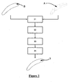
- Grâce à la comparaison entre le nuage de points au réel A et le modèle théorique B, en référence à la
figure 3 , on créée un modèle topologique 31 permettant d'identifier 32 les zones en sous épaisseur et les zones en surépaisseur. On procède ensuite au calcul de la trajectoire d'usinage sur le modèle déformé par morphing 33 et on usine la pièce 34 pour obtenir la pièce réparée 3. - Le modèle topologique 31 comprend un ensemble de points de coordonnées (x,y,z,Δ) avec x, y et z les coordonnées de chaque point du nuage A selon trois axes orthogonaux, Δ étant la projection du point sur la normale du carreau du maillage théorique le plus proche dudit point.
- Ainsi si Δ a une valeur positive, la pièce endommagée 1 possède un excès de matière par rapport au modèle théorique B, au contraire si Δ a une valeur négative, la pièce endommagée 1 possède un défaut de matière par rapport au modèle théorique B. Des logiciels de conception assistée par ordinateur (CAO), tels que le logiciel commercialisé sous la marque déposée CATIA permettent d'obtenir des modèles topologiques 31 de manière automatisée et ainsi de visualiser les zones en surépaisseur qui doivent être usinées et les zones qui doivent recevoir un apport de matière.
- Pour déformer le modèle théorique B par morphing, il est nécessaire de repérer les meilleurs points à déplacer du modèle théorique B pour interpoler au mieux un maximum de points du nuage de points au réel A. Ces points sont appelés points de contrôle. On peut ainsi déformer le maillage théorique B et obtenir un maillage correspondant à la pièce endommagée 1.
- L'analyse du modèle topologique 32 pour réaliser le morphing est une étape complexe qui nécessite de l'expérience et un haut niveau d'expertise. En effet, la modification locale de la position d'un point de contrôle du maillage théorique B a des influences globales sur la forme et la position des surfaces de Bézier déformées et sur la tangence de raccordement entre les surfaces.
- Des conditions de courbure et de tangence doivent également être respectées au niveau des irrégularités de la forme des aubes. Les experts calculent les meilleurs points du modèle théorique B à déplacer afin que les écarts entre le modèle théorique déformé et les points du nuage de points A soient le plus faible possible.
- Le procédé de morphing est une étape lente et complexe qui entraîne une variabilité des résultats selon l'expert choisi. Le calcul de la fonction de morphing est donc très délicat. Il n'est donc pas adapté à une application industrielle.
- La présente invention vise à pallier au moins ces inconvénients.
- L'invention concerne un procédé de réparation par usinage d'une pièce à usiner, telle qu'une aube de turbomachine, à partir d'un profil connu de la pièce, le procédé comprenant les étapes suivantes :
- a. une acquisition des coordonnées de points sur une enveloppe de la pièce à usiner, l'ensemble des points formant un nuage de points;
- b. une comparaison du profil connu avec le nuage de points pour définir des zones en surépaisseur ou sous épaisseur sur la pièce à usiner;
- c. une déformation du profil par un procédé de morphing pour que le profil déformé interpole le nuage de points, la déformation du profil définissant une fonction de morphing et
- d. l'usinage de la pièce à usiner par une machine d'usinage, paramétrée à partir de la fonction de morphing
- Conformément à l'invention, le procédé est caractérisé par le fait que, la déformation du profil comprend une comparaison de chaque zone en surépaisseur ou sous épaisseur de la pièce à usiner à des configurations élémentaires de déformation (CED) se présentant chacune sous la forme d'une portion de maillage, simulant le profil (B), et de points simulant des points du nuage de points (A), les configurations élémentaires de déformation (CED) étant classées dans une base de données, la base de données associant pour chaque configuration élémentaire de déformation (CED) des paramètres de la fonction de morphing.
- Le procédé de l'invention permet avantageusement d'usiner une pièce de manière automatique, les paramètres de la fonction de morphing étant connus dans la base de données.
- A partir de cette fonction de morphing, on déduit la fonction de paramétrage de la machine qui va usiner la pièce à réparer. L'automatisation du processus de morphing permet de mettre en place un processus industriel stable et parfaitement répétable de ces opérations sur des pièces dont les écarts et les défauts de forme ne sont pas répétables. D'où les gains de temps, de qualité et donc de coût.
- De préférence, le profil de la pièce se présente sous la forme d'un maillage de points.
- De préférence encore, les coordonnées et les vecteurs de déplacement des points du maillage à déplacer pour interpoler le nuage de points, dits points de contrôles, sont des paramètres de la fonction de morphing.
- De préférence toujours, une machine de mesure tridimensionnelle (MMT), avec ou sans palpage, réalise l'acquisition des coordonnées des points sur l'enveloppe de la pièce à usiner.
- De préférence toujours, la pièce à usiner est une pièce ayant reçue un ajout de matière.
- L'invention concerne également, la base de données de la mise en oeuvre du procédé de l'invention, associant à une configuration élémentaire de déformation (CED) des paramètres de la fonction de morphing.
- L'invention sera mieux comprise à l'aide de la description suivante et du dessin annexé sur lequel :
- la
figure 1 représente l'étape d'acquisition des coordonnées de points sur une enveloppe de la pièce à usiner selon l'invention; - la
figure 2 représente les étapes de création d'un maillage théorique selon l'invention ; - la
figure 3 représente les étapes du procédé de l'invention permettant de réparer une pièce endommagée; - la
figure 4 représente les étapes permettant de calculer la trajectoire d'usinage sur le modèle théorique, déformé par morphing, selon le procédé de l'invention ; - la
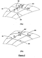
figure 5a représente une configuration élémentaire de déformation selon l'invention ; - la
figure 5b représente la configuration élémentaire de déformation de lafigure 5a après déformation par morphing; et - la
figure 6 représente une zone en surépaisseur de la pièce à usiner. - En référence à la
figure 4 , après une analyse du modèle topologique global 32, les zones en surépaisseur ou en sous épaisseur sont comparées à des configurations élémentaires de déformation (CED) 102 stockées dans une base de données 100 avec des paramètres 101 permettant de déformer par morphing 41 le modèle théorique B afin de calculer la trajectoire d'usinage 33. - Une configuration élémentaire de déformation (CED) 102 est une surface paramétrée définie par des courbes de Bézier. Une CED comprend ici une portion de maillage, formée de carreaux pouvant avoir différents motifs, et des points représentant le profil réel de la surface paramétrée. La distance entre les points et les carreaux du maillage représentant les écarts de distances entre le profil théorique et réel de la surface paramétrée.
- Une configuration élémentaire de déformation (CED) est une analyse du point de vue local de la fonction de morphing. Une CED comprend une portion de maillage, simulant une portion de maillage du profil théorique de la pièce, et plusieurs points simulant des points de mesure de la pièce réelle. Une configuration élémentaire CED est une représentation des différences qui peuvent exister localement entre une pièce réelle et un profil théorique.
- Afin de mieux définir la CED, en référence à la
figure 5a , la CED 5 comprend une portion de maillage comportant neufs carreaux, disposés sur trois lignes et trois colonnes, chaque carreau ayant quatre côtés. La CED 5 comprend également quatre points A1, A2, A3, A4. - La distance, séparant respectivement un point de son carreau le plus proche est représenté par une droite s'étendant selon la normale dudit carreau en partant desdits points A1-A4. Ces distances sont similaires à la mesure des écarts Δ définie précédemment pour le modèle topologique. Plus ces distances sont faibles, plus le maillage est proche des points.
- Il va de soi qu'une CED, se présentant sous la forme d'une surface paramétrée, qui pour chaque point de la surface associe une valeur représentant un écart de déformation, conviendrait également. Il va de soi qu'une représentation mathématique de la CED aussi bien matricielle qu'analytique conviendrait également.
- Sur la portion de maillage de la CED 5, toujours en référence à la
figure 5a , quatre points de contrôles B1-B4 sont représentés. Ils correspondent aux coins du carreau central du maillage. Le déplacement d'un point de contrôle entraîne une modification globale des courbes de Bézier du maillage, affectant aussi bien la longueur des différents côtés des carreaux que leur tangence les uns par rapport aux autres. - La sélection des points de contrôle à déplacer ainsi que leur vecteur de déplacement permettent de déformer le maillage par morphing et d'interpoler au mieux les points A1-A4.
- Pour chaque CED de la base de données 100, ces paramètres ont été calculés préalablement par un expert et insérés dans la base de données 100. En référence à la
figure 4 , la base de données 100 met en relation chaque CED 102 avec ces paramètres 101. A titre d'exemple, lafigure 5b représente la déformation par morphing du maillage de la CED de lafigure 5a . Le point de contrôle B2 est déplacé selon le vecteur V au point B2', permettant ainsi au maillage d'interpoler les points A1-A4. On remarque, par exemple, que les écarts entre les points A1-A4 et le maillage ont diminué sur lafigure 5b . Dans la base de données 100, la CED 5 est associée avec les coordonnées du point B2 à déplacer et son vecteur de déplacement V. - Dans cet exemple, un seul point de contrôle, en l'occurrence B2, est déplacé. Toutefois, plusieurs points de contrôle peuvent être, de manière similaire, déplacés pour interpoler les points A1-A4.
- La base de données 100 comprend de nombreux CED 102, ayant des maillages et des positions de points variés, pour lequel la déformation optimale du maillage a été calculée afin d'interpoler au mieux les points. Les CED 102 se distinguent les uns des autres par leur courbure, concavité, nombre de carreaux du maillage, connexité des raccordements et tangence des carreaux.
- Après avoir décrit la structure des moyens de l'invention, son fonctionnement et sa mise en oeuvre vont maintenant être abordés.
- En référence à la
figure 3 , un nuage de points A d'une pièce endommagée 1, ayant reçu éventuellement un ajout de matière 2, est comparé au modèle théorique B afin de créer un modèle topologique global 31 de la pièce 1. - L'analyse du modèle topologique global 32 permet d'identifier des zones topologiques locales correspondant aux zones en sous épaisseur ou en surépaisseur. Après analyse, on réalise une étape de calcul de la trajectoire d'usinage 33 et une étape d'usinage 34 de la pièce 1. En référence à la
figure 6 , ces zones topologiques locales 20 sont respectivement comparées aux CED 102 de la base de données 100. - Cette comparaison est réalisée par différence de formes, par rapport d'échelle et par analyse en fonction de la position des carreaux du maillage théorique B.
- La base de données 100 comprend une grande variété de CED 102 pour permettre d'identifier la zone topologique locale sélectionnée 20, les CED 102 constituant une base au sens mathématique. Lorsque la CED est identifiée, les paramètres 101 associés à la CED 102 sont lus dans la base de données 100, ces paramètres 102 permettant de déformer le maillage B de la zone topologique locale 20.
- Cette étape de comparaison est réalisée pour chaque zone topologique locale 20 afin d'obtenir l'ensemble des paramètres 101 locaux nécessaires à la déformation du maillage théorique B. Ces paramètres 101 sont nécessaires au calcul de la trajectoire d'usinage 33 sur le modèle théorique B pour redonner à la pièce endommagée 1 son profil aérodynamique.
- Lorsqu'une zone topologique locale 20 ne peut pas être identifiée dans la base de données 100, la déformation du maillage de ladite zone 20 est réalisée par un expert qui détermine les points de contrôle à déplacer ainsi que leur vecteur de déplacement.
- La zone topologique locale et les paramètres de déformation de cette zone sont insérés dans la base de données 100, permettant de réutiliser les paramètres calculés par l'expert ultérieurement. L'enrichissement de la base de données 100permet d'éviter à un expert de résoudre plusieurs fois des problèmes similaires. La déformation par morphing est automatisée.
- 1
- pièce à usiner
- 2
- Ajout de matière (patch)
- 3
- Pièce usinée
- 5
- Configuration élémentaire de déformation
- 11
- Étape d'ajout de matière
- 12
- Étape de mesure volumique de la pièce
- 20
- Zone topologique locale
- 21
- Étape de calcul aérodynamique
- 22
- Étape de réalisation du modèle théorique
- 31
- Création du modèle topologique
- 32
- Analyse du modèle topologique global
- 33
- Calcul de la trajectoire d'usinage
- 34
- Usinage
- 41
- Déformation du modèle théorique par morphing
- 100
- Base de données
- 101
- Configurations élémentaires de déformation
- 102
- Paramètres de la fonction de morphing
Claims (6)
- Procédé de réparation par usinage d'une pièce à usiner (1), telle qu'une aube de turbomachine, à partir d'un profil connu de la pièce (B), le procédé comprenant les étapes suivantes :a. une acquisition des coordonnées de points sur une enveloppe de la pièce à usiner (1), l'ensemble des points formant un nuage de points (A);b. une comparaison (31) du profil connu (B) avec le nuage de points (A) pour définir des zones en surépaisseur ou sous épaisseur (20) sur la pièce à usiner (1);c. une déformation (32) du profil (B) par un procédé de morphing pour que le profil déformé interpole le nuage de points (A), la déformation du profil définissant une fonction de morphing etd. l'usinage (34) de la pièce à usiner (1) par une machine d'usinage, paramétrée à partir de la fonction de morphingcaractérisé par le fait que, la déformation du profil (B) comprend une comparaison de chaque zone en surépaisseur ou sous épaisseur (20) de la pièce à usiner (1) à des configurations élémentaires de déformation (CED) (5) se présentant chacune sous la forme d'une portion de maillage, simulant le profil (B), et de points simulant des points du nuage de points (A), les configurations élémentaires de déformation (CED) (5) étant classées dans une base de données (100), la base de données (100) associant pour chaque configuration élémentaire de déformation (CED) (102) les paramètres de la fonction de morphing (101).
- Procédé selon la revendication 1, dans lequel le profil de la pièce se présente sous la forme d'un maillage de points (B).
- Procédé selon la revendication 2, dans lequel les coordonnées et les vecteurs de déplacement des points du maillage (B) à déplacer pour interpoler le nuage de points (A), dits points de contrôles, sont des paramètres de la fonction de morphing (101).
- Procédé selon l'une des revendications 1 à 3, dans lequel une machine de mesure tridimensionnelle (MMT), avec ou sans palpage, réalise l'acquisition des coordonnées des points sur l'enveloppe de la pièce à usiner.
- Procédé selon l'une des revendications 1 à 4, dans lequel la pièce à usiner (1) est une pièce (1) ayant reçue un ajout de matière (2).
- Base de données (100) de la mise en oeuvre du procédé selon l'une des revendications 1 à 5, associant à une configuration élémentaire de déformation (CED) (102) des paramètres de la fonction de morphing (101).
Applications Claiming Priority (2)
| Application Number | Priority Date | Filing Date | Title |
|---|---|---|---|
| FR0702021A FR2913901B1 (fr) | 2007-03-20 | 2007-03-20 | Procede de reparation de pieces usinees telles que des aubes de turbomachines ou des pales de dam |
| PCT/FR2008/000367 WO2008135656A1 (fr) | 2007-03-20 | 2008-03-19 | Procédé de réparation de pièces usinées telles que des aubes de turbomachines ou des pales de dam |
Publications (2)
| Publication Number | Publication Date |
|---|---|
| EP2125282A1 EP2125282A1 (fr) | 2009-12-02 |
| EP2125282B1 true EP2125282B1 (fr) | 2010-12-08 |
Family
ID=38657050
Family Applications (1)
| Application Number | Title | Priority Date | Filing Date |
|---|---|---|---|
| EP08787820A Active EP2125282B1 (fr) | 2007-03-20 | 2008-03-19 | Procédé de réparation de pièces usinées telles que des aubes de turbomachines ou des pales de dam |
Country Status (11)
| Country | Link |
|---|---|
| US (1) | US8881392B2 (fr) |
| EP (1) | EP2125282B1 (fr) |
| JP (1) | JP5087794B2 (fr) |
| CN (1) | CN101641181B (fr) |
| AT (1) | ATE490841T1 (fr) |
| CA (1) | CA2684954C (fr) |
| DE (1) | DE602008003904D1 (fr) |
| ES (1) | ES2357466T3 (fr) |
| FR (1) | FR2913901B1 (fr) |
| RU (1) | RU2476301C2 (fr) |
| WO (1) | WO2008135656A1 (fr) |
Families Citing this family (41)
| Publication number | Priority date | Publication date | Assignee | Title |
|---|---|---|---|---|
| DE102009033234A1 (de) * | 2009-07-14 | 2011-01-27 | Alstom Technology Ltd. | Verfahren zum Bearbeiten des Rotors einer Turbine |
| EP2361720B1 (fr) * | 2010-02-22 | 2012-12-12 | Alstom Technology Ltd | Procédé de réparation et/ou de traitement d'un composant, notamment d'une turbine à gaz |
| DE102010024084A1 (de) * | 2010-06-17 | 2011-12-22 | Rolls-Royce Deutschland Ltd & Co Kg | Verfahren zur Herstellung von Blisks |
| GB201103222D0 (en) * | 2011-02-24 | 2011-04-13 | Imp Innovations Ltd | A turbine wheel,a turbine and a use thereof |
| FR2976835B1 (fr) * | 2011-06-21 | 2013-06-28 | Snecma | Procede d'usinage adaptatif pour aubes de fonderie |
| FR2983757B1 (fr) * | 2011-12-07 | 2014-09-12 | Snecma | Procede de reformage d'une aube de turbomachine comportant au moins une zone deformee par grenaillage |
| FR2989608B1 (fr) * | 2012-04-24 | 2015-01-30 | Snecma | Procede d'usinage du bord de fuite d'une aube de turbomachine |
| US9495726B1 (en) * | 2012-05-23 | 2016-11-15 | DEP Autoline, Inc. | System and method for morphing a CAD design element |
| US20140075754A1 (en) * | 2012-09-18 | 2014-03-20 | United Technologies Corporation | System method for machining aircraft components |
| EP2965159B1 (fr) | 2013-03-05 | 2020-05-06 | Rolls-Royce Corporation | Usinage adaptatif de surfaces de composant et perçage de trou |
| US9817393B2 (en) | 2013-03-08 | 2017-11-14 | Rolls-Royce Corporation | Adaptive machining of components |
| US9346145B2 (en) * | 2013-03-27 | 2016-05-24 | Av & R Vision And Robotics Inc | Apparatus and method for blending added material with base material on a manufactured component |
| US9323869B1 (en) * | 2013-04-16 | 2016-04-26 | Msc.Software Corporation | Mesh-based shape optimization systems and methods |
| FR3006078B1 (fr) * | 2013-05-22 | 2016-06-03 | Coriolis Software | Procede de definition de trajectoires de fibre a partir d'un champ vectoriel |
| FR3006079B1 (fr) | 2013-05-22 | 2015-05-15 | Coriolis Software | Procede de definition de trajectoires de fibre a partir de courbes ou grille de contrainte |
| CN103488832B (zh) * | 2013-09-23 | 2016-07-06 | 大连理工大学 | 一种复杂曲面零件破损区域的几何修复方法 |
| WO2015044681A1 (fr) * | 2013-09-30 | 2015-04-02 | Bae Systems Plc | Traitement d'informations pour la production d'une porte d'avion ou d'un panneau d'avion |
| EP2853963A1 (fr) * | 2013-09-30 | 2015-04-01 | BAE Systems PLC | Production d'objet |
| GB2518682A (en) * | 2013-09-30 | 2015-04-01 | Bae Systems Plc | Information processing |
| EP2853964A1 (fr) * | 2013-09-30 | 2015-04-01 | BAE Systems PLC | Traitement d'informations pour produire une porte d'avion ou un panneau d'avion |
| US10162331B2 (en) | 2015-03-02 | 2018-12-25 | Rolls-Royce Corporation | Removal of material from a surface of a dual walled component |
| CN105057969B (zh) * | 2015-05-29 | 2017-12-08 | 西安交通大学 | 基于微束等离子焊接和电火花精整的整体叶盘修复方法 |
| CN106774145A (zh) * | 2016-12-23 | 2017-05-31 | 华中科技大学 | 一种用于生成无干涉的五轴加工轨迹的投影算法 |
| EP3531318B1 (fr) * | 2018-02-22 | 2023-05-24 | General Electric Company | Procédé de remodelage d'un composant |
| CN108563872B (zh) * | 2018-04-16 | 2022-11-01 | 西北工业大学 | 网格参数化方法及基于该网格参数化方法的轴流涡轮气动优化设计方法 |
| WO2020176841A1 (fr) * | 2019-02-28 | 2020-09-03 | Georgia Tech Research Corporation | Systèmes et procédés de prédiction de la géométrie et de la structure interne de pales de turbine |
| CN113441725B (zh) * | 2020-03-27 | 2023-09-22 | 斗山重工业建设有限公司 | 利用增材制造的涡轮机叶片的修复方法 |
| GB202006769D0 (en) | 2020-05-07 | 2020-06-24 | Rolls Royce Plc | Method of machining a component |
| FR3115596B1 (fr) * | 2020-10-26 | 2023-07-28 | Safran Aircraft Engines | Procédé d’évaluation d’une durée de vie d’une pièce de turbomachine |
| CN113579639A (zh) * | 2021-07-23 | 2021-11-02 | 中国电建集团长春发电设备有限公司 | 一种修复立式磨煤机碾磨件的方法及系统 |
| US11828190B2 (en) | 2021-11-18 | 2023-11-28 | General Electric Company | Airfoil joining apparatus and methods |
| US12523979B2 (en) | 2022-04-05 | 2026-01-13 | Rtx Corporation | Method of repairing a stack of integrally bladed rotors |
| US12410711B2 (en) | 2022-04-05 | 2025-09-09 | Rtx Corporation | Bladed rotor inspection, analysis and repair systems and methods |
| US12318877B2 (en) | 2022-04-05 | 2025-06-03 | Rtx Corporation | Blend approach based inspection and analysis systems and methods |
| US12664333B2 (en) | 2022-04-05 | 2026-06-23 | Rtx Corporation | Systems and methods for generating blend repair models |
| US12037918B2 (en) | 2022-04-05 | 2024-07-16 | Rtx Corporation | Systems and methods for parameterization of inspected bladed rotor analysis |
| US11860060B2 (en) | 2022-04-05 | 2024-01-02 | Rtx Corporation | Integrally bladed rotor analysis and repair systems and methods |
| CN115255609B (zh) * | 2022-07-22 | 2024-10-11 | 广西科技大学 | 一种用于复杂曲面飞秒激光微孔加工的自适应定位方法 |
| FR3145300B1 (fr) * | 2023-01-27 | 2025-12-26 | Safran Aircraft Engines | Ajustage de piece de turbomachine |
| CN116243657B (zh) * | 2023-05-11 | 2023-08-22 | 无锡透平叶片有限公司 | 大叶片加工变形的控制方法 |
| CN118378495B (zh) * | 2024-06-25 | 2024-08-30 | 北京航空航天大学 | 液体火箭发动机的涡轮性能可靠性仿真方法和系统 |
Family Cites Families (17)
| Publication number | Priority date | Publication date | Assignee | Title |
|---|---|---|---|---|
| SU1655749A1 (ru) * | 1989-01-30 | 1991-06-15 | Институт Электросварки Им.Е.О.Патона | Способ восстановлени изделий из жаропрочных сплавов |
| JPH09192979A (ja) * | 1996-01-18 | 1997-07-29 | Hitachi Ltd | 3次元加工装置およびその方法 |
| US6748112B1 (en) * | 1998-07-28 | 2004-06-08 | General Electric Company | Method and apparatus for finding shape deformations in objects having smooth surfaces |
| US20020128790A1 (en) * | 2001-03-09 | 2002-09-12 | Donald Woodmansee | System and method of automated part evaluation including inspection, disposition recommendation and refurbishment process determination |
| US6536110B2 (en) * | 2001-04-17 | 2003-03-25 | United Technologies Corporation | Integrally bladed rotor airfoil fabrication and repair techniques |
| US6701615B2 (en) * | 2002-03-08 | 2004-03-09 | General Electric Company | Inspection and sorting system and method for part repair |
| US6912446B2 (en) * | 2002-10-23 | 2005-06-28 | General Electric Company | Systems and methods for automated sensing and machining for repairing airfoils of blades |
| RU2235147C1 (ru) * | 2002-11-22 | 2004-08-27 | Государственное образовательное учреждение высшего профессионального образования "Удмуртский государственный университет " | Способ повышения прочности деталей, работающих при импульсном давлении |
| EP1457853A1 (fr) * | 2003-03-14 | 2004-09-15 | General Electric Company | Procédé et appareil pour "reverse engineering" et re-construction des éléments |
| DE10319494A1 (de) * | 2003-04-30 | 2004-11-18 | Mtu Aero Engines Gmbh | Verfahren zur Reparatur und/oder Modifikation von Bauteilen einer Gasturbine |
| US6969821B2 (en) * | 2003-06-30 | 2005-11-29 | General Electric Company | Airfoil qualification system and method |
| JP2005028556A (ja) * | 2003-07-11 | 2005-02-03 | M & J:Kk | 自由曲面加工方法 |
| US20050038817A1 (en) * | 2003-08-15 | 2005-02-17 | Siemens Westinghouse Power Corporation | System and method for processing inspection data for evaluating degradation of coating on components |
| US7293006B2 (en) * | 2004-04-07 | 2007-11-06 | Integrated Project Solutions Llc | Computer program for storing electronic files and associated attachments in a single searchable database |
| US7472478B2 (en) * | 2004-10-29 | 2009-01-06 | Honeywell International Inc. | Adaptive machining and weld repair process |
| FR2882533B1 (fr) * | 2005-02-25 | 2007-07-06 | Snecma Moteurs Sa | Procede de reparation de disque aubage monobloc, eprouvette de debut et de fin campagne |
| JP4642551B2 (ja) * | 2005-05-24 | 2011-03-02 | Ntn株式会社 | 転動体を有する機械構造物の形状設計方法 |
-
2007
- 2007-03-20 FR FR0702021A patent/FR2913901B1/fr not_active Expired - Fee Related
-
2008
- 2008-03-19 DE DE602008003904T patent/DE602008003904D1/de active Active
- 2008-03-19 US US12/532,173 patent/US8881392B2/en active Active
- 2008-03-19 CN CN200880009204.4A patent/CN101641181B/zh active Active
- 2008-03-19 JP JP2009554061A patent/JP5087794B2/ja active Active
- 2008-03-19 AT AT08787820T patent/ATE490841T1/de not_active IP Right Cessation
- 2008-03-19 RU RU2009138526/02A patent/RU2476301C2/ru active
- 2008-03-19 CA CA2684954A patent/CA2684954C/fr active Active
- 2008-03-19 EP EP08787820A patent/EP2125282B1/fr active Active
- 2008-03-19 ES ES08787820T patent/ES2357466T3/es active Active
- 2008-03-19 WO PCT/FR2008/000367 patent/WO2008135656A1/fr not_active Ceased
Also Published As
| Publication number | Publication date |
|---|---|
| CN101641181A (zh) | 2010-02-03 |
| US20100095526A1 (en) | 2010-04-22 |
| RU2009138526A (ru) | 2011-04-27 |
| DE602008003904D1 (de) | 2011-01-20 |
| CA2684954A1 (fr) | 2008-11-13 |
| WO2008135656A1 (fr) | 2008-11-13 |
| EP2125282A1 (fr) | 2009-12-02 |
| CA2684954C (fr) | 2015-12-22 |
| CN101641181B (zh) | 2011-08-31 |
| FR2913901B1 (fr) | 2009-09-04 |
| RU2476301C2 (ru) | 2013-02-27 |
| US8881392B2 (en) | 2014-11-11 |
| FR2913901A1 (fr) | 2008-09-26 |
| JP2010522089A (ja) | 2010-07-01 |
| ATE490841T1 (de) | 2010-12-15 |
| ES2357466T3 (es) | 2011-04-26 |
| JP5087794B2 (ja) | 2012-12-05 |
Similar Documents
| Publication | Publication Date | Title |
|---|---|---|
| CA2684954C (fr) | Procede de reparation de pieces usinees telles que des aubes de turbomachines ou des pales de dam | |
| US8442665B2 (en) | System, method, and apparatus for repairing objects | |
| US7797828B2 (en) | Adaptive machining and weld repair process | |
| CA2648901C (fr) | Procede de choix d'un arrangement de secteurs pour un distributeur pour turbomachine | |
| EP3242177A1 (fr) | Procédé de réparation adaptative de pales à profil aérodynamique | |
| EP2075527B1 (fr) | Procédé de mesure par digitalisation des sections de passage d'un secteur de distributeur pour turbomachine | |
| EP2724201B1 (fr) | Procede d'usinage adaptatif pour aubes de fonderie | |
| US12318877B2 (en) | Blend approach based inspection and analysis systems and methods | |
| US12410711B2 (en) | Bladed rotor inspection, analysis and repair systems and methods | |
| FR3116456A1 (fr) | Procede de reparation d’une piece de turbomachine et installation correspondante | |
| US20230315951A1 (en) | Systems and methods for inspected bladed rotor analysis | |
| EP3963282B1 (fr) | Procédé de contrôle dimensionnel d'une pièce de turbomachine | |
| US12037918B2 (en) | Systems and methods for parameterization of inspected bladed rotor analysis | |
| EP3408827B1 (fr) | Méthode de contrôle d'une pièce de machine | |
| EP1672170A1 (fr) | Procédé de réparation de disques aubages monoblocs | |
| Kaszynski et al. | Uncertainties of an automated optical 3D geometry measurement, modeling, and analysis process for mistuned ibr reverse engineering | |
| US20230315069A1 (en) | Inspection data management systems and methods | |
| US20260093235A1 (en) | Systems and methods for repairing a stack of integrally bladed rotors |
Legal Events
| Date | Code | Title | Description |
|---|---|---|---|
| PUAI | Public reference made under article 153(3) epc to a published international application that has entered the european phase |
Free format text: ORIGINAL CODE: 0009012 |
|
| 17P | Request for examination filed |
Effective date: 20091006 |
|
| AK | Designated contracting states |
Kind code of ref document: A1 Designated state(s): AT BE BG CH CY CZ DE DK EE ES FI FR GB GR HR HU IE IS IT LI LT LU LV MC MT NL NO PL PT RO SE SI SK TR |
|
| RIN1 | Information on inventor provided before grant (corrected) |
Inventor name: GASNE, LUDOVIC Inventor name: KERNEIS, STEPHANE Inventor name: DERRIEN, GERARD Inventor name: LEONETTI, CLAUDE |
|
| DAX | Request for extension of the european patent (deleted) | ||
| RIC1 | Information provided on ipc code assigned before grant |
Ipc: G05B 19/4097 20060101ALN20100527BHEP Ipc: B23P 6/00 20060101AFI20100527BHEP Ipc: F01D 5/00 20060101ALI20100527BHEP Ipc: G05B 19/425 20060101ALN20100527BHEP |
|
| RTI1 | Title (correction) |
Free format text: METHOD FOR REPAIRING MACHINED COMPONENTS SUCH AS TURBOMACHINE BLADES OR BLISK BLADES |
|
| GRAP | Despatch of communication of intention to grant a patent |
Free format text: ORIGINAL CODE: EPIDOSNIGR1 |
|
| GRAS | Grant fee paid |
Free format text: ORIGINAL CODE: EPIDOSNIGR3 |
|
| GRAA | (expected) grant |
Free format text: ORIGINAL CODE: 0009210 |
|
| AK | Designated contracting states |
Kind code of ref document: B1 Designated state(s): AT BE BG CH CY CZ DE DK EE ES FI FR GB GR HR HU IE IS IT LI LT LU LV MC MT NL NO PL PT RO SE SI SK TR |
|
| REG | Reference to a national code |
Ref country code: GB Ref legal event code: FG4D Free format text: NOT ENGLISH |
|
| REG | Reference to a national code |
Ref country code: CH Ref legal event code: EP |
|
| REG | Reference to a national code |
Ref country code: IE Ref legal event code: FG4D |
|
| REF | Corresponds to: |
Ref document number: 602008003904 Country of ref document: DE Date of ref document: 20110120 Kind code of ref document: P |
|
| REG | Reference to a national code |
Ref country code: SE Ref legal event code: TRGR |
|
| REG | Reference to a national code |
Ref country code: NL Ref legal event code: VDEP Effective date: 20101208 |
|
| REG | Reference to a national code |
Ref country code: ES Ref legal event code: FG2A Ref document number: 2357466 Country of ref document: ES Kind code of ref document: T3 Effective date: 20110426 |
|
| PG25 | Lapsed in a contracting state [announced via postgrant information from national office to epo] |
Ref country code: NO Free format text: LAPSE BECAUSE OF FAILURE TO SUBMIT A TRANSLATION OF THE DESCRIPTION OR TO PAY THE FEE WITHIN THE PRESCRIBED TIME-LIMIT Effective date: 20110308 Ref country code: LT Free format text: LAPSE BECAUSE OF FAILURE TO SUBMIT A TRANSLATION OF THE DESCRIPTION OR TO PAY THE FEE WITHIN THE PRESCRIBED TIME-LIMIT Effective date: 20101208 |
|
| LTIE | Lt: invalidation of european patent or patent extension |
Effective date: 20101208 |
|
| PG25 | Lapsed in a contracting state [announced via postgrant information from national office to epo] |
Ref country code: CY Free format text: LAPSE BECAUSE OF FAILURE TO SUBMIT A TRANSLATION OF THE DESCRIPTION OR TO PAY THE FEE WITHIN THE PRESCRIBED TIME-LIMIT Effective date: 20101208 Ref country code: FI Free format text: LAPSE BECAUSE OF FAILURE TO SUBMIT A TRANSLATION OF THE DESCRIPTION OR TO PAY THE FEE WITHIN THE PRESCRIBED TIME-LIMIT Effective date: 20101208 Ref country code: BG Free format text: LAPSE BECAUSE OF FAILURE TO SUBMIT A TRANSLATION OF THE DESCRIPTION OR TO PAY THE FEE WITHIN THE PRESCRIBED TIME-LIMIT Effective date: 20110308 Ref country code: HR Free format text: LAPSE BECAUSE OF FAILURE TO SUBMIT A TRANSLATION OF THE DESCRIPTION OR TO PAY THE FEE WITHIN THE PRESCRIBED TIME-LIMIT Effective date: 20101208 Ref country code: NL Free format text: LAPSE BECAUSE OF FAILURE TO SUBMIT A TRANSLATION OF THE DESCRIPTION OR TO PAY THE FEE WITHIN THE PRESCRIBED TIME-LIMIT Effective date: 20101208 Ref country code: LV Free format text: LAPSE BECAUSE OF FAILURE TO SUBMIT A TRANSLATION OF THE DESCRIPTION OR TO PAY THE FEE WITHIN THE PRESCRIBED TIME-LIMIT Effective date: 20101208 Ref country code: SI Free format text: LAPSE BECAUSE OF FAILURE TO SUBMIT A TRANSLATION OF THE DESCRIPTION OR TO PAY THE FEE WITHIN THE PRESCRIBED TIME-LIMIT Effective date: 20101208 Ref country code: AT Free format text: LAPSE BECAUSE OF FAILURE TO SUBMIT A TRANSLATION OF THE DESCRIPTION OR TO PAY THE FEE WITHIN THE PRESCRIBED TIME-LIMIT Effective date: 20101208 |
|
| REG | Reference to a national code |
Ref country code: IE Ref legal event code: FD4D |
|
| PG25 | Lapsed in a contracting state [announced via postgrant information from national office to epo] |
Ref country code: CZ Free format text: LAPSE BECAUSE OF FAILURE TO SUBMIT A TRANSLATION OF THE DESCRIPTION OR TO PAY THE FEE WITHIN THE PRESCRIBED TIME-LIMIT Effective date: 20101208 Ref country code: PT Free format text: LAPSE BECAUSE OF FAILURE TO SUBMIT A TRANSLATION OF THE DESCRIPTION OR TO PAY THE FEE WITHIN THE PRESCRIBED TIME-LIMIT Effective date: 20110408 Ref country code: EE Free format text: LAPSE BECAUSE OF FAILURE TO SUBMIT A TRANSLATION OF THE DESCRIPTION OR TO PAY THE FEE WITHIN THE PRESCRIBED TIME-LIMIT Effective date: 20101208 Ref country code: IE Free format text: LAPSE BECAUSE OF FAILURE TO SUBMIT A TRANSLATION OF THE DESCRIPTION OR TO PAY THE FEE WITHIN THE PRESCRIBED TIME-LIMIT Effective date: 20101208 Ref country code: IS Free format text: LAPSE BECAUSE OF FAILURE TO SUBMIT A TRANSLATION OF THE DESCRIPTION OR TO PAY THE FEE WITHIN THE PRESCRIBED TIME-LIMIT Effective date: 20110408 Ref country code: GR Free format text: LAPSE BECAUSE OF FAILURE TO SUBMIT A TRANSLATION OF THE DESCRIPTION OR TO PAY THE FEE WITHIN THE PRESCRIBED TIME-LIMIT Effective date: 20110309 |
|
| PG25 | Lapsed in a contracting state [announced via postgrant information from national office to epo] |
Ref country code: SK Free format text: LAPSE BECAUSE OF FAILURE TO SUBMIT A TRANSLATION OF THE DESCRIPTION OR TO PAY THE FEE WITHIN THE PRESCRIBED TIME-LIMIT Effective date: 20101208 Ref country code: PL Free format text: LAPSE BECAUSE OF FAILURE TO SUBMIT A TRANSLATION OF THE DESCRIPTION OR TO PAY THE FEE WITHIN THE PRESCRIBED TIME-LIMIT Effective date: 20101208 Ref country code: RO Free format text: LAPSE BECAUSE OF FAILURE TO SUBMIT A TRANSLATION OF THE DESCRIPTION OR TO PAY THE FEE WITHIN THE PRESCRIBED TIME-LIMIT Effective date: 20101208 |
|
| BERE | Be: lapsed |
Owner name: SNECMA Effective date: 20110331 |
|
| PLBE | No opposition filed within time limit |
Free format text: ORIGINAL CODE: 0009261 |
|
| STAA | Information on the status of an ep patent application or granted ep patent |
Free format text: STATUS: NO OPPOSITION FILED WITHIN TIME LIMIT |
|
| PG25 | Lapsed in a contracting state [announced via postgrant information from national office to epo] |
Ref country code: MC Free format text: LAPSE BECAUSE OF NON-PAYMENT OF DUE FEES Effective date: 20110331 Ref country code: DK Free format text: LAPSE BECAUSE OF FAILURE TO SUBMIT A TRANSLATION OF THE DESCRIPTION OR TO PAY THE FEE WITHIN THE PRESCRIBED TIME-LIMIT Effective date: 20101208 |
|
| 26N | No opposition filed |
Effective date: 20110909 |
|
| PG25 | Lapsed in a contracting state [announced via postgrant information from national office to epo] |
Ref country code: MT Free format text: LAPSE BECAUSE OF FAILURE TO SUBMIT A TRANSLATION OF THE DESCRIPTION OR TO PAY THE FEE WITHIN THE PRESCRIBED TIME-LIMIT Effective date: 20101208 Ref country code: BE Free format text: LAPSE BECAUSE OF NON-PAYMENT OF DUE FEES Effective date: 20110331 |
|
| REG | Reference to a national code |
Ref country code: DE Ref legal event code: R097 Ref document number: 602008003904 Country of ref document: DE Effective date: 20110909 |
|
| REG | Reference to a national code |
Ref country code: CH Ref legal event code: PL |
|
| PG25 | Lapsed in a contracting state [announced via postgrant information from national office to epo] |
Ref country code: LI Free format text: LAPSE BECAUSE OF NON-PAYMENT OF DUE FEES Effective date: 20120331 Ref country code: CH Free format text: LAPSE BECAUSE OF NON-PAYMENT OF DUE FEES Effective date: 20120331 |
|
| PG25 | Lapsed in a contracting state [announced via postgrant information from national office to epo] |
Ref country code: LU Free format text: LAPSE BECAUSE OF NON-PAYMENT OF DUE FEES Effective date: 20110319 |
|
| PGFP | Annual fee paid to national office [announced via postgrant information from national office to epo] |
Ref country code: ES Payment date: 20120309 Year of fee payment: 5 |
|
| PG25 | Lapsed in a contracting state [announced via postgrant information from national office to epo] |
Ref country code: TR Free format text: LAPSE BECAUSE OF FAILURE TO SUBMIT A TRANSLATION OF THE DESCRIPTION OR TO PAY THE FEE WITHIN THE PRESCRIBED TIME-LIMIT Effective date: 20101208 |
|
| PG25 | Lapsed in a contracting state [announced via postgrant information from national office to epo] |
Ref country code: HU Free format text: LAPSE BECAUSE OF FAILURE TO SUBMIT A TRANSLATION OF THE DESCRIPTION OR TO PAY THE FEE WITHIN THE PRESCRIBED TIME-LIMIT Effective date: 20101208 |
|
| REG | Reference to a national code |
Ref country code: ES Ref legal event code: FD2A Effective date: 20140606 |
|
| PG25 | Lapsed in a contracting state [announced via postgrant information from national office to epo] |
Ref country code: ES Free format text: LAPSE BECAUSE OF NON-PAYMENT OF DUE FEES Effective date: 20130320 |
|
| REG | Reference to a national code |
Ref country code: FR Ref legal event code: PLFP Year of fee payment: 8 |
|
| REG | Reference to a national code |
Ref country code: FR Ref legal event code: PLFP Year of fee payment: 9 |
|
| REG | Reference to a national code |
Ref country code: FR Ref legal event code: PLFP Year of fee payment: 10 |
|
| REG | Reference to a national code |
Ref country code: FR Ref legal event code: CD Owner name: SAFRAN AIRCRAFT ENGINES, FR Effective date: 20170719 |
|
| REG | Reference to a national code |
Ref country code: FR Ref legal event code: PLFP Year of fee payment: 11 |
|
| PGFP | Annual fee paid to national office [announced via postgrant information from national office to epo] |
Ref country code: SE Payment date: 20260323 Year of fee payment: 19 |
|
| PGFP | Annual fee paid to national office [announced via postgrant information from national office to epo] |
Ref country code: GB Payment date: 20260324 Year of fee payment: 19 |
|
| PGFP | Annual fee paid to national office [announced via postgrant information from national office to epo] |
Ref country code: DE Payment date: 20260320 Year of fee payment: 19 |
|
| PGFP | Annual fee paid to national office [announced via postgrant information from national office to epo] |
Ref country code: FR Payment date: 20260318 Year of fee payment: 19 |
|
| PGFP | Annual fee paid to national office [announced via postgrant information from national office to epo] |
Ref country code: IT Payment date: 20260331 Year of fee payment: 19 |