EP2124702B1 - Geschirrspülmaschine und korbanordnung dafür - Google Patents
Geschirrspülmaschine und korbanordnung dafür Download PDFInfo
- Publication number
- EP2124702B1 EP2124702B1 EP07860780.1A EP07860780A EP2124702B1 EP 2124702 B1 EP2124702 B1 EP 2124702B1 EP 07860780 A EP07860780 A EP 07860780A EP 2124702 B1 EP2124702 B1 EP 2124702B1
- Authority
- EP
- European Patent Office
- Prior art keywords
- dish
- dish holders
- holders
- dishwasher
- rack assembly
- Prior art date
- Legal status (The legal status is an assumption and is not a legal conclusion. Google has not performed a legal analysis and makes no representation as to the accuracy of the status listed.)
- Not-in-force
Links
- 230000003247 decreasing effect Effects 0.000 claims description 3
- 238000004851 dishwashing Methods 0.000 claims 1
- 238000005406 washing Methods 0.000 description 30
- 230000000712 assembly Effects 0.000 description 20
- 238000000429 assembly Methods 0.000 description 20
- XLYOFNOQVPJJNP-UHFFFAOYSA-N water Substances O XLYOFNOQVPJJNP-UHFFFAOYSA-N 0.000 description 16
- 238000005507 spraying Methods 0.000 description 8
- 239000007921 spray Substances 0.000 description 6
- 230000007246 mechanism Effects 0.000 description 4
- 238000012986 modification Methods 0.000 description 3
- 230000004048 modification Effects 0.000 description 3
- 230000000694 effects Effects 0.000 description 2
- 238000003780 insertion Methods 0.000 description 2
- 230000037431 insertion Effects 0.000 description 2
- 229910000831 Steel Inorganic materials 0.000 description 1
- 239000003599 detergent Substances 0.000 description 1
- 239000010794 food waste Substances 0.000 description 1
- 230000002452 interceptive effect Effects 0.000 description 1
- 239000002184 metal Substances 0.000 description 1
- 238000000465 moulding Methods 0.000 description 1
- 239000010959 steel Substances 0.000 description 1
Images


Classifications
-
- A—HUMAN NECESSITIES
- A47—FURNITURE; DOMESTIC ARTICLES OR APPLIANCES; COFFEE MILLS; SPICE MILLS; SUCTION CLEANERS IN GENERAL
- A47L—DOMESTIC WASHING OR CLEANING; SUCTION CLEANERS IN GENERAL
- A47L15/00—Washing or rinsing machines for crockery or tableware
- A47L15/42—Details
- A47L15/50—Racks ; Baskets
- A47L15/502—Cutlery baskets
-
- A—HUMAN NECESSITIES
- A47—FURNITURE; DOMESTIC ARTICLES OR APPLIANCES; COFFEE MILLS; SPICE MILLS; SUCTION CLEANERS IN GENERAL
- A47L—DOMESTIC WASHING OR CLEANING; SUCTION CLEANERS IN GENERAL
- A47L15/00—Washing or rinsing machines for crockery or tableware
- A47L15/42—Details
- A47L15/50—Racks ; Baskets
- A47L15/504—Arrangements for changing the height of racks
-
- A—HUMAN NECESSITIES
- A47—FURNITURE; DOMESTIC ARTICLES OR APPLIANCES; COFFEE MILLS; SPICE MILLS; SUCTION CLEANERS IN GENERAL
- A47L—DOMESTIC WASHING OR CLEANING; SUCTION CLEANERS IN GENERAL
- A47L15/00—Washing or rinsing machines for crockery or tableware
- A47L15/42—Details
- A47L15/50—Racks ; Baskets
- A47L15/505—Inserts, e.g. for holding baby bottles, stemware or cups
Definitions
- a dishwasher and a rack assembly therefor are disclosed herein.
- a dishwasher is an apparatus that washes away food residue attached to dishware, such as bowls, spoons, chopsticks,and various culinary tools (hereinafter, referred to as "dishware” or “dishes”) using a detergent and wash water.
- dishware such as bowls, spoons, chopsticks,and various culinary tools (hereinafter, referred to as "dishware” or “dishes”) using a detergent and wash water.
- a washing tub or space having a cavity of a predetermined size is provided in the dishwasher.
- One or more rack assembly may be provided and configured to be inserted into and withdrawn from the washing tub.
- the rack assembly may include one or more dish holder(s) on which dishes are placed.
- the dish holder(s) may be provided in the rack assembly in various shapes according to kinds and sizes of the dishes.
- a wash water spraying apparatus that sprays wash water onto the dishes placed in the rack assembly is provided in the washing tub. After the dishes are placed in the dish holder(s) of the
- the dishes may include a plurality of cutleries and culinary tools that are narrow and long.
- the cutleries may include, for example, a knife, a spoon, and a fork.
- the culinary tools may include, for example, a ladle, a kitchen knife, and a turner. A plurality of cutleries and culinary tools may be placed into the rack assembly.
- the related art dishwasher since only specific dishes can be arranged in a single dish holder, the related art dishwasher is limited to washing such specific dishes. If various dish holders are provided in the rack assembly in order to solve this problem, the space efficiency of the rack assembly is reduced.
- the rack assembly in order to wash various dishes in dishwasher, the rack assembly must have various type dish holders.
- various type dish holders it is practically impossible to provide various type dish holders in the rack assembly of a restricted size and it is very inefficient to use the dishwasher. That is, when the various type dish holders are provided in the rack assembly, the number of the dishes to be washed by the dishwasher at once is limited. In other words, the space efficiency of the rack assembly is deteriorated, and the capacity of the dishwasher is substantially decreased.
- EP 0 186 157 relates to a domestic dishwasher with a cabinet interior enclosed by a door and comprising at least a spray arm device, a removable crockery basket and a separate cutlery basket in which items of cutlery can be placed for the purpose of washing, the cutlery basket provides cutlery slots in the form of cutlery holders and cutlery rests for individual items or cutlery placed separately and lengthwise alongside one another in the slots.
- the dishwasher according to embodiments disclosed herein is capable of washing various types of dishes selectively placed in dish holders of a rack assembly, and the space efficiency of the rack assembly is improved.
- a dishwasher that includes a rack assembly drawably provided in a washing tub, first, second, and third dish holders that are provided in the rack assembly and in which dishes of different sizes and shapes may be selectively inserted and are supported, wherein the first dish holder and the second dish holder are separated from each other, and the third dish holder is provided between the first and second dish holders and has a height different from those of the first and second dish holders.
- the third dish holder may have a height lower than the heights of the first and second dish holders.
- the third dish holder may have a height where the dishes that are inserted between the first and second dish holders are placed.
- a plurality of the first and second dish holders may be alternately aligned in a line, and a plurality of third dish holders may be respectively provided between the first and second dish holders.
- the first, second, and third dish holders may be provided in a plurality of rows on the rack assembly in parallel to each other, and the first, second, and third dish holders that are respectively provided in the plurality of rows may be provided to face each other. Further, the first, second, and third dish holders that are respectively provided in the plurality of rows may be alternately provided.
- the dishwasher may further include a plurality of dish holders of a height different from those of the first, second, and third dish holders may be provided between the first and third dish holders and between the second and third dish holders to face each other about the third dish holder.
- a dishwasher that includes a rack assembly drawably provided in a washing tub, and a plurality of dish holders that are provided in the rack assembly and in which dishes may be alternately placed.
- the dish holders may include a plurality of dish holder groups respectively aligned in a line in the rack assembly.
- the plurality of dish holder groups may be provided in the rack assembly to be separated from each other.
- the dish holder groups may be alternately provided in the row directions of the dish holder groups such that the dishes placed in the dish holders do not interfere with each other.
- the dish holder groups may be provided in parallel to each other in the rack assembly.
- the dish holder groups may be provided such that odd rows and even rows of the dish holder groups are alternately provided in the row directions of the dish holder groups to prevent the interference between the dishes that are placed in the dish holders.
- the dish holders may include insertion single pairs of protrusions being separated from each other in which table cutleries or culinary tools may be inserted and are fixed.
- the dish holder groups may be configured such that the dish holders are aligned with the direction where the single pairs of insertion protrusions are separated from each other.
- the rack assembly may include a frame that is drawably provided in an upper side of the washing tub, and a basket that is detachably mounted to the frame and in which the dish holders are formed.
- the dish holders may be integrally formed with the baskets, such as by molding.
- the dish holders in which dishes having different sizes and shapes are selectively provided are formed in the rack assemblies, various kinds of dishes may be washed together and the various kinds of dishes may be freely provided in the rack assemblies so that space efficiency is improved.
- FIG. 1 is a front perspective view of a dishwasher according to an embodiment that does not form part of the invention but represents background art that is useful for understanding the invention.
- FIG. 2 is an exploded perspective view of a frame of a rack assembly and baskets of the dishwasher of FIG. 1 .
- FIG. 3 is an enlarged perspective view of a portion "A" of FIG. 2 .
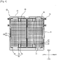
- FIG. 4 is a plan view of the frame of the rack assembly and the baskets of FIG. 1 .
- FIG. 5 is an enlarged plan view of a portion "B" of FIG. 3 .
- FIG. 6 is a plan view illustrating a state in which dishes are placed in the baskets of the dishwasher of FIG. 1 .
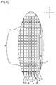
- FIG. 7 is a sectional view taken along line C-C in FIG. 6 .
- a dishwasher 1 may include a washing tub or space 3 provided in a cabinet 2 and having a cavity of a predetermined size, a plurality of rack assemblies 4, 5, and 6 configured to be inserted into and withdrawn from the washing tub 3 and in which dishes may be placed, and a wash water spraying apparatus 7 provided in the washing tub 3 to spray wash water onto the dishes placed in the rack assemblies 4, 5, and 6.
- An entrance or opening 8 through which the rack assemblies 4, 5, and 6 are inserted into and withdrawn from the washing tub 3 may be formed in a front surface of the cabinet 2 and the washing tub 3.
- a door 9 that opens and closes the entrance 8 may be rotatably attached to the cabinet 2. The door 9 may be rotatably opened and closed in a drop-down manner, as shown in FIG. 2 .
- the wash water spraying apparatus 7 may be configured to spray the wash water onto the dishes placed in the rack assemblies 4, 5, and 6. That is, the wash water spraying apparatus 7 may include a pump (not shown) provided between the cabinet 2 and the washing tub 3 to pump the wash water, a plurality of nozzles 10 that spray the wash water pumped by the pump onto the dishes, and a wash water channel 11 formed between the nozzles 10 and the pump.
- the nozzles 10 may be provided at a lower side and/or an upper side of the rack assemblies 4, 5, and 6.
- the rack assemblies 4, 5, and 6 may be provided in the washing tub 3 spaced apart from each other in a vertical (columnwise) direction. That is, a first rack assembly 4 and a second rack assembly 5 may be provided at a lower portion and at a middle portion of the washing tub 3, such that tableware, such as dishes, bowels, and similar dishware may be accommodated therein. A third rack assembly 6 may be provided at an upper portion of the washing tub 3, such that cutleries 50 and 51 and culinary tools may be accommodated therein.
- one, two, three, or more rack assemblies may be provided in the washing tub 3 in accordance with the design conditions of the dishwasher 1 and the kinds of the dishes placed in the rack assemblies may vary.
- the rack assemblies 4, 5, and 6 may include racks 12 and 13 in which the dishes may placed. Movement guides 14 and 15 may be provided for the racks 12 and 13 in the washing tub 3 to movably support the racks 12 and 13 in a forward and backward direction of movement.
- the racks 12 and 13 may be in the form of a grill so that the wash water sprayed from the wash water spraying apparatus 7 is transmitted to the dishes.
- the racks 12 of the first rack assembly 4 and the second rack assembly 5 may be formed of, for example, metal rods in the form of a grill.
- the rack 13 of the third rack assembly 6 may include baskets 30 molded in the form of a grill.
- the movement guide 14 of the first rack assembly 4 may include a plurality of wheels rotatably provided at a lower side of the rack 12 such that the rack 12 can move along inner surfaces of the door 9 and the washing tub 3.
- the movement guides 15 of the second rack assembly 5 and the third rack assembly 6 may include roller mechanisms 16 provided at lateral sides of the racks 12 and 13, and guide rails 17 provided at lateral sides of the washing tub 3 that guide movement of the roller mechanisms 16.
- the guide rails 17 may be provided at lateral sides of the racks 12 and 13, and the roller mechanisms 16 may be provided at lateral sides of the washing tub 3.
- the third rack assembly 6 may include a frame 20 configured to be inserted into and withdrawn from the washing tub 3 by the movement guides 15, and one or more baskets 30 detachably provided on the frame 20.
- the one or more baskets 30 may include a plurality of dish holders to support dishware, such as cutleries 50 and 51 and/or culinary tools.
- the frame 20 may be a rectangular frame made of, for example, steel rod.
- the frame 20 may include an upper frame 21 and a lower frame 22.
- the upper frame 21 and lower frame 22 may be rectangular in shape and may be separated from each other in the vertical direction.
- a connecting frame 23 may connect the upper frame 21 to the lower frame 22.
- the connecting frame 23 may include a plurality of supporting devices 25 on which the baskets 30 may be supported or received.
- the connecting frame 23 may include a plurality of connecting device 24 whose upper and lower sides are respectively connected to the upper frame 21 and the lower frame 22.
- the plurality of supporting devices 25 may protrude from the connecting device 24 toward an inner space defined by the frame 20 and on which the baskets 30 may be placed. If necessary, a plurality of frames 20 may be provided.
- the roller mechanisms 16 may be provided at right and left sides of the frame 20 to correspond to the guide rails 17 of the washing tub 3, respectively.
- a space defined by the frame 20 is partitioned into a right side space and a left side space such that two basket loading or receiving spaces 20a and 20b are formed will be described.
- the baskets 30 may be basket-shaped molded products in which the cutleries 50 and 51 may be placed.
- the baskets 30 may be detachably provided in the basket receiving spaces 20a and 20b in the vertical direction.
- Each of the baskets 30 may have a plurality of supported devices 31 to be placed on the supporting devices 25.
- the baskets 30 may include a plurality of dish holders formed on bottoms of the baskets 30 and integrally formed therewith. The cutleries 50 and 51 and the culinary tools may be inserted and fixed to the dish holder.
- the dish holders includes first, second, and third dish holders 32, 33, and 34 that protrude from the baskets 30 and support the cutleries 50 and 51.
- the first dish holders 32 and the second dish holders 33 may protrude from the bottoms of the baskets 30 upwardly, and may be separated from each other such that a large kitchen cutlery 51, such as a kitchen knife, may be inserted into and fixed by the first dish holders 32.
- the first dish holders 32 and the second dish holders 33 have heights different from each other.
- the third dish holders 34 may be provided between the first and second dish holders 32 and 33, such that table cutlery 50 thinner than the kitchen cutlery 51 may be inserted into and supported by the third dish holders 34.
- the table cutlery 50 may include, for example, a knife, a fork, or similar table cutlery.
- the third dish holders 34 may have a height lower than the heights of the first and second dish holders 32 and 33.
- the protruding height of the third dish holders 34 may be equal to a height to which kitchen cutlery 51 inserted between the first dish holders 32 and the second dish holder 33 extends, such that the kitchen cutlery 51 that is inserted between the first and second dish holders 32 and 33 is stably supported by the third dish holders 34, as shown in FIG. 7 .
- the first, second, and third dish holders 32, 33, and 34 may be formed on the baskets 30 to face each other in a longitudinal direction of the cutleries 50 and 51 or the culinary tools in order to stably support the cutleries 50 and 51 or the culinary tools at a plurality of positions.
- first, second, and third dish holders 32, 33, and 34 may be formed on the baskets 30 to face each other in a longitudinal direction of the cutleries 50 and 51 or the culinary tools in order to stably support the cutleries 50 and 51 or the culinary tools at a plurality of positions.
- a plurality of the first dish holder 32 and the second dish holders 33 may be alternately positioned along the row direction (the line X-X) formed by the first, second, and third dish holders 32, 33, and 34.
- the third dish holders 34 may be respectively provided between the first and second dish holders 33 and 34. Therefore, the first, second, and third dish holders 32, 33, and 34 form dish holder groups 40 that are arranged in single lines on the baskets 30.
- Each of the dish holder groups 40 may include a first dish holder group 42 provided at one side of the basket 30 and a second dish holder group 44 provided at the opposite side of the basket 30 in parallel to the first dish holder group 42.
- the first and second dish holder groups 42 and 44 may be provided in the row direction (the line X-X) in an alternate manner with respect to a direction (the line Y-Y) where the first and second dish holder groups 42 and 44 are separated from each other so that the cutleries 50 and 51 do not interfere with each other.
- the row directions (the line X-X) of the first and second dish holder groups 42 and 44 are referred to as right-to-left directions of the baskets 30, and the spacing directions (the line Y-Y) of the first and second dish holder groups 42 and 44 are referred to as front-to-rear directions of the baskets 30.
- the first and second dish holder groups 42 and 44 may be configured to extend a predetermined distance in opposite directions along the right-to-left direction (the line X-X) or extend by different distances in any one direction in the right-to-left direction (the line X-X). A difference between the extended distances of the first and second dish holder groups 42 and 44 may be smaller than an extended distance difference between the first and second dish holders 32 and 33.
- the first, second, and third dish holders 32, 33, and 34 of the second dish holder group 44 are provided to face each other in spaces formed among the first, second, and third dish holders 32, 33, and 34 of the first dish holder group 42 will be described.
- the first, second, and third dish holders 32, 33, and 34 constituting the first and second dish holder groups 42 and 44 may be provided to face each other.
- the door 9 is opened to open the entrance 8 formed in the front side of the dishwasher 1, and the rack assemblies 4, 5, and 6 are withdrawn from the inside of the washing tub 3.
- Various kinds of dishes to be washed are placed in the rack assemblies 4, 5, and 6.
- the rack assemblies 4, 5, and 6 are inserted into the washing tub 3 and the door 9 is closed to shield the entrance 8.
- the dishwasher 1 is operated so that the dishes placed on the rack assemblies 4, 5, and 6 are washed by spraying the wash water from the wash water spraying apparatus 7.
- the cutleries 50 and 51 or culinary tools may be selectively inserted into and supported between the first, second, and third dish holders 32 formed in the baskets 30 of the third rack assembly 6.
- grips of the cutleries 50 and 51 may be selectively inserted between and fixed by two dish holders among the first, second, and third dish holders 32, 33, and 34 that are formed in the baskets 30.
- the grip of the large kitchen cutlery 51 such as a kitchen knife, is inserted between and is supported by the first and second dish holders 32 and 33. Therefore, the blade of the kitchen cutlery 51 is placed on the bottom of the basket 30 and the grip of the kitchen cutlery 51 is placed on the end of the third dish holders 34 such that the kitchen cutlery 51 is prevented from moving from side to side by the first and second dish holders 32 and 33.
- the third dish holders 34 compensate for the height difference between the blade and the grip of the kitchen cutlery 51.
- the grip of the small kitchen cutlery 50 such as a knife, a fork, and similar cutlery, is inserted between and is supported by the first and third dish holders 32 and 34 or the second and third dish holders 33 and 34.
- the table cutlery 50 is placed on the bottoms of the baskets 30 to prevent the table cutlery 50 from moving from side to side by the first and second dish holders 32 and 34 or the second and third dish holders 33 and 34.
- the third rack assembly 6 may selectively accommodate two kinds of the cutleries 50 and 51 of different sizes and shapes due to the first, second, and third dish holders 32, 33, and 34.
- the first, second, and third dish holders 32, 33, and 34 may be commonly used for the two kinds of the cutleries 50 and 51. Therefore, since the first, second, and third dish holders 32, 33, and 34 are used regardless of the kind of dishes, the space efficiency of the basket(s) 30 of the third rack assembly 6 is improved.
- first and second dish holder groups 42 and 44 in which the plurality of the first, second, and third dish holders 32, 33, and 34 are respectively aligned in a line may be formed in the basket(s) 30 respectively and the first and second dish holder groups 42 and 44 may be alternately provided
- the cutleries 50 and 51 that are provided in the first and second dish holder groups 42 and 44 may be also alternately provided. That is, the cutleries 50 and 51 that are inserted into the first dish holder groups 41 are respectively placed between the cutleries 50 and 51 placed in the second dish holder groups 44. Therefore, the cutleries 50 and 51 that are inserted into the first and second dish holder groups 42 and 44 may be prevented from interfering with each other..
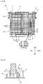
- FIG. 8 is a sectional view illustrating a state in which dishes are placed in baskets of a dishwasher according to an embodiment of the invention.
- like reference numerals have been used to indicate like elements illustrated in FIG. 7 .
- FIG. 8 only aspects of the dishwasher according to this embodiment different from those of the dishwasher previously discussed will be described.
- basket(s) 130 of the dishwasher illustrated in FIG. 8 and the basket(s) 30 of the dishwasher 1 illustrated in FIGS. 1 to 7 is that single pairs of fourth dish holders 135 may be provided to face each other about the third dish holders 134 between first and second dish holders 132 and 133. Since the first, second, and third dish holders 132, 133, and 134 are identical to or similar to the first, second, and third dish holders 32, 33, and 34 illustrated in FIGS. 3 to 6 , further description thereof will be omitted.
- the fourth dish holders 135 may have a height lower than the heights of the first and second dish holders 132 and 133 and higher than the height of the third dish holders 134.
- the fourth dish holders 135 may be respectively provided between the first and third dish holders 132 and 134 and between the second and third dish holders 133 and 134.
- a thin table cutlery 150 may be provided between the first and fourth dish holders 132 and 135, between the second and fourth dish holders 133 and 135, and between the third and fourth dish holders 134 and 135. Moreover, kitchen cutleries 151 and 152 larger than the table cutlery 150 may be selectively provided between the first and second dish holders 132 and 133 and between the single pairs of fourth dish holders 135 in accordance with sizes and shapes.
- the large kitchen cutlery 151 may be inserted between and supported by the first and second dish holders 132 and 133.
- the lower side of the kitchen cutlery 151 may be placed on the ends of the fourth dish holders 135 and may be stably supported by the fourth dish holders 135.
- the kitchen cutlery 152 smaller than the kitchen cutlery 151 inserted between the first and second dish holders 132 and 133 may be inserted between and supported by the pair of fourth dish holders 135.
- the lower side of the kitchen cutlery 152 is placed on the ends of the third dish holders 134 and is stably supported by the third dish holders 134.
- the three kinds of the cutleries 150, 151, and 152 may be selectively supported by the first, second, third, and fourth dish holders 132, 133, 134, and 135 and the first, second, third, and fourth dish holders 132, 133, 134, and 135 may be commonly used for the three kinds of cutleries 150, 151, and 152, in comparison to the other embodiment, the space efficiency of the basket(s) 130 may be improved.
- FIG. 9 is a sectional view illustrating a state in which dishes are placed in basket(s) of a dishwasher according to another embodiment of the invention.
- like reference numerals have been used to indicate like elements illustrated in FIG. 7 .
- FIG. 9 only aspects of the dishwasher according to this embodiment different from those of the dishwashers previously discussed will be described.
- the fifth and sixth dish holders 235 and 236 may be provided between the first and third dish holders 232 and 234 or the second and third dish holders 233 and 234 to be separated from each other by the same distance.
- the pair of fifth dish holders 235 may be close to the first and second dish holders 232 and 233.
- the pair of sixth dish holders 236 may be close to the third dish holders 234. Therefore, the fifth dish holders 235 may be provided between the first and sixth dish holders 232 and 236 and the second and sixth dish holders 234 and 236, respectively.
- the sixth dish holders 236 may be provided between the third and fifth dish holders 234 and 235.
- the fifth and sixth dish holders 235 and 236 may be lower than the first and second dish holders 232 and 233 and higher than the third dish holders 234.
- the fifth dish holders 235 may be lower than the first and second dish holders 232 and 233 and higher than the sixth dish holders 236.
- the sixth dish holders 236 may be lower than the fifth dish holders 235 and higher than the third dish holders 234. That is, the fifth and sixth dish holders 235 and 236 may be formed so that the heights of the dish holders are gradually reduced from the first and second dish holders 232 and 233 toward the third dish holders 234.
- a thin table cutlery 250 may be provided between the first and fifth dish holders 232 and 235, between the second and fifth dish holders 233 and 235, between the fifth and sixth dish holders 235 and 236, and between the third and sixth dish holders 234 and 236.
- kitchen cutleries 251, 252, and 253 larger than the table cutlery 250 may be selectively provided between the first and second dish holders 232 and 233, between the pair of fifth dish holders 235, or the pair of sixth dish holders 236 in accordance with sizes and shapes.
- the largest kitchen cutlery 251 may be inserted between and supported by the first and second dish holders 232 and 233. At this time, the lower part of the kitchen cutlery 251 may be supported on the ends of the fifth dish holders 235 to be stably supported by the fifth dish holders 235.
- the kitchen cutlery 253 smaller than the kitchen cutlery 251 inserted between the first and second dish holders 232 and 233 may be inserted into and supported by the pair of fifth dish holders 235.
- the lower part of the kitchen cutlery 253 may be supported on the ends of the sixth dish holders 236 to be stably supported by the sixth dish holders 236.
- the kitchen cutlery 252 smaller than the kitchen cutleries 251 and 253 inserted into the first and second dish holders 232 and 233 or the pair of fifth dish holders 235 may be inserted into and supported by the pair of sixth dish holders 236.
- the lower part of the kitchen cutlery 252 may be supported on the ends of the third dish holders 234 to be stably supported by the third dish holders 234.
- the space efficiency of the basket(s) 230 may be improved.
- dish holders to which the cutleries and the culinary tools may be fixed may be formed in the racks of one and two-column rack assemblies.
- at least three dish holders may have different heights so that a pair of dish holders are provided between the first and second dish holders based on the third dish holders to face each other.
- any reference in this specification to "one embodiment”, “an embodiment”, “example embodiment”, etc. means that a particular feature, structure, or characteristic described in connection with the embodiment is included in at least one embodiment of the invention.
- the appearances of such phrases in various places in the specification are not necessarily all referring to the same embodiment.
- the dish holders in which dishes having different sizes and shapes are selectively provided are formed in the rack assemblies, various kinds of dishes may be washed together and the various kinds of dishes may be freely provided in the rack assemblies so that space efficiency is improved.
Landscapes
- Washing And Drying Of Tableware (AREA)
Claims (10)
- Geschirrspülmaschine, aufweisend:ein Gehäuse (2) mit einem darin angeordneten Geschirrspülraum; undmindestens eine Korbanordnung (4, 5, 6), die konfiguriert ist, um Geschirr darin zu halten und um in das Gehäuse eingesetzt und aus dem Gehäuse heraus genommen zu werden, wobei die mindestens eine Korbanordnung (4, 5, 6) einen Rahmen (20) und mindestens einen Korb (30; 130; 230) aufweist, der konfiguriert ist, um von dem Rahmen (20) getragen zu werden, und wobei der mindestens eine Korb (30; 130; 230) aufweist:eine Anzahl von Geschirrhaltern, die konfiguriert sind, um Geschirrteile oder Utensilien in dem mindestens einen Korb (30; 130; 230) sicher zu halten,wobei die Anzahl von Geschirrhaltern nebeneinander angeordnete erste und zweite Geschirrhalter (32, 33; 132, 133; 232, 233) unterschiedlicher Höhe aufweist,dadurch gekennzeichnet, dassdie Anzahl von Geschirrhaltern ferner eine Anzahl von dritten Geschirrhaltern (34; 134; 234) aufweist, die eine andere Höhe haben als die ersten und zweiten Geschirrhalter (32, 33; 132, 133; 232, 233), wobei die Anzahl von Geschirrhaltern (32, 33, 34; 132, 133, 134; 232, 233, 234) in einer Linie wiederholt abnehmender, dann zunehmender Höhe angeordnet ist.
- Geschirrspülmaschine nach Anspruch 1, wobei die Anzahl von Geschirrhaltern sich von einer unteren Oberfläche des mindestens einen Korbs (30; 130; 230) aufwärts erstreckt.
- Geschirrspülmaschine nach Anspruch 1, wobei einer der ersten Geschirrhalter derart zwischen zwei der zweiten Geschirrhalter angeordnet ist, dass die Geschirrhalter abwechselnde Höhen haben.
- Geschirrspülmaschine nach Anspruch 1, wobei eine Anzahl von Geschirrhaltern an einem ersten Ende des mindestens einen Korbs (30; 130; 230) bereitgestellt ist und eine Anzahl von Geschirrhaltern an einem zweiten Ende des mindestens einen Korbs (30; 130; 230) bereitgestellt ist.
- Geschirrspülmaschine nach Anspruch 4, wobei die Anzahl von Geschirrhaltern an dem ersten Ende versetzt von der Anzahl von Geschirrhaltern an dem zweiten Ende angeordnet ist.
- Geschirrspülmaschine nach Anspruch 4, wobei die Anzahl von Geschirrhaltern an dem ersten Ende sich parallel zu der Anzahl von Geschirrhaltern an dem zweiten Ende erstreckt.
- Geschirrspülmaschine nach Anspruch 1, wobei die Anzahl von Geschirrhaltern in einer Linie angeordnet ist und wobei ein zweiter Geschirrhalter (33; 133; 233) zwischen jeweils einem ersten und dritten Geschirrhalter (32, 34; 132, 134; 232, 234) angeordnet ist.
- Geschirrspülmaschine nach Anspruch 1, wobei die Anzahl von Geschirrhaltern ferner eine Anzahl von vierten Geschirrhaltern (135) aufweist, die eine andere Höhe haben als die ersten, zweiten und dritten Geschirrhalter (132, 133, 134).
- Geschirrspülmaschine nach Anspruch 8, wobei die Anzahl von Geschirrhaltern in einer Linie wiederholt abnehmender, dann zunehmender Höhe angeordnet ist.
- Geschirrspülmaschine nach Anspruch 1, wobei die Anzahl von Geschirrhaltern in parallelen Geschirrhalter-Linien angeordnet ist.
Applications Claiming Priority (3)
| Application Number | Priority Date | Filing Date | Title |
|---|---|---|---|
| KR1020060138628A KR20080062621A (ko) | 2006-12-29 | 2006-12-29 | 식기세척기 |
| KR1020060138627A KR20080062620A (ko) | 2006-12-29 | 2006-12-29 | 식기세척기 |
| PCT/KR2007/007003 WO2008082232A1 (en) | 2006-12-29 | 2007-12-29 | Dishwasher and rack assembly therefor |
Publications (3)
| Publication Number | Publication Date |
|---|---|
| EP2124702A1 EP2124702A1 (de) | 2009-12-02 |
| EP2124702A4 EP2124702A4 (de) | 2016-12-28 |
| EP2124702B1 true EP2124702B1 (de) | 2018-03-07 |
Family
ID=39582205
Family Applications (1)
| Application Number | Title | Priority Date | Filing Date |
|---|---|---|---|
| EP07860780.1A Not-in-force EP2124702B1 (de) | 2006-12-29 | 2007-12-29 | Geschirrspülmaschine und korbanordnung dafür |
Country Status (3)
| Country | Link |
|---|---|
| US (1) | US20080156358A1 (de) |
| EP (1) | EP2124702B1 (de) |
| WO (1) | WO2008082232A1 (de) |
Families Citing this family (19)
| Publication number | Priority date | Publication date | Assignee | Title |
|---|---|---|---|---|
| EP2364636B2 (de) | 2010-03-12 | 2020-08-12 | Electrolux Home Products Corporation N.V. | Geschirrfach, Geschirrspülmaschinenkorb und Geschirrspülmaschine |
| KR101764294B1 (ko) | 2011-01-19 | 2017-08-04 | 삼성전자주식회사 | 식기세척기 |
| TR201106338A1 (tr) * | 2011-06-27 | 2013-01-21 | Arçeli̇k Anoni̇m Şi̇rketi̇ | Çekmece içeren bir bulaşık makinası. |
| DE102012016762B4 (de) * | 2012-08-27 | 2017-07-27 | Haier Deutschland GmbH | Geschirrspülmaschine |
| ES2646042T3 (es) * | 2012-09-26 | 2017-12-11 | Foshan Shunde Midea Washing Appliances Mfg. Co., Ltd | Aparato de apoyo de bandeja para lavavajillas, conjunto de bandeja para cubiertos y lavavajillas |
| CN104127160B (zh) * | 2013-05-03 | 2016-12-28 | 美的集团股份有限公司 | 用于洗碗机的托盘支撑装置、刀叉托盘组件和洗碗机 |
| WO2014094893A1 (en) | 2012-12-21 | 2014-06-26 | Electrolux Home Products Corporation N. V. | Cutlery rack |
| US10149596B2 (en) | 2012-12-21 | 2018-12-11 | Electrolux Home Products Corporation N.V. | Cutlery tray module for a dishwasher and dishwasher comprising at least one cutlery tray module |
| ITTO20121172A1 (it) * | 2012-12-31 | 2014-07-01 | Indesit Co Spa | Vassoio portaposate per una lavastoviglie |
| AU354063S (en) | 2013-08-05 | 2014-03-03 | Electrolux Appliances AB | A dishwasher component |
| DE102013013649A1 (de) * | 2013-08-16 | 2015-02-19 | Haier Deutschland GmbH | Geschirrspülmaschine |
| US20150245762A1 (en) * | 2014-02-28 | 2015-09-03 | Whirlpool Corporation | Glasses rack for dishwasher |
| US10149595B2 (en) | 2016-11-07 | 2018-12-11 | Whirlpool Corporation | Utensil rack for a dishwasher |
| DE102018007987A1 (de) * | 2018-10-09 | 2020-04-09 | Manfred Braig | Geschirrspüler |
| CN111110161A (zh) * | 2018-11-01 | 2020-05-08 | 博西华电器(江苏)有限公司 | 洗碗机 |
| KR20200029343A (ko) * | 2019-07-16 | 2020-03-18 | 김우일 | 식기세척기 및 이를 이용한 세척방법 |
| US11389047B2 (en) * | 2020-07-16 | 2022-07-19 | Haier Us Appliance Solutions, Inc. | Dishwasher rack support assembly |
| US11986144B2 (en) | 2022-03-15 | 2024-05-21 | Whirlpool Corporation | Dishwasher with tray |
| CN120091788A (zh) | 2022-10-23 | 2025-06-03 | 埃科莱布美国股份有限公司 | 用于可重复使用的塑料器皿的盘碟架和器皿洗涤系统 |
Family Cites Families (9)
| Publication number | Priority date | Publication date | Assignee | Title |
|---|---|---|---|---|
| US4339051A (en) * | 1980-08-18 | 1982-07-13 | General Electric Company | Silverware basket |
| DE3447302A1 (de) * | 1984-12-24 | 1986-06-26 | Miele & Cie GmbH & Co, 4830 Gütersloh | Geschirrspuelmaschine fuer den haushalt |
| JPH0998927A (ja) * | 1995-10-09 | 1997-04-15 | Toto Ltd | 食器洗浄機 |
| DE19736793C2 (de) * | 1997-08-23 | 2000-04-06 | Whirlpool Co | Geschirrkorb für eine Geschirrspülmaschine |
| WO2001087133A1 (en) * | 2000-05-15 | 2001-11-22 | Arçelik A.Ş. | Dishwasher basket with vertically adjustable rack |
| DE10056488A1 (de) * | 2000-11-15 | 2002-05-23 | Bsh Bosch Siemens Hausgeraete | Einsatz für einen Geschirrkorb einer Geschirrspülmaschine |
| DE10347765A1 (de) * | 2003-10-14 | 2005-05-12 | Bsh Bosch Siemens Hausgeraete | Geschirrkorb mit höhenverstellbaren Ablagen |
| US20060250058A1 (en) * | 2005-03-29 | 2006-11-09 | Whirlpool Corporation | Dishwasher with Utensil Rack and Slides Therefor |
| US7455066B2 (en) * | 2005-03-29 | 2008-11-25 | Whirlpool Corporation | Dishwasher utensil rack and utensil basket therefor |
-
2007
- 2007-12-12 US US11/954,633 patent/US20080156358A1/en not_active Abandoned
- 2007-12-29 EP EP07860780.1A patent/EP2124702B1/de not_active Not-in-force
- 2007-12-29 WO PCT/KR2007/007003 patent/WO2008082232A1/en not_active Ceased
Non-Patent Citations (1)
| Title |
|---|
| None * |
Also Published As
| Publication number | Publication date |
|---|---|
| EP2124702A1 (de) | 2009-12-02 |
| US20080156358A1 (en) | 2008-07-03 |
| WO2008082232A1 (en) | 2008-07-10 |
| EP2124702A4 (de) | 2016-12-28 |
Similar Documents
| Publication | Publication Date | Title |
|---|---|---|
| EP2124702B1 (de) | Geschirrspülmaschine und korbanordnung dafür | |
| EP2124701B1 (de) | Geschirrspülmaschine und korbanordnung dafür | |
| EP2292140B1 (de) | Besteckbehälter, insbesondere ein Bestecktablett und/oder ein Besteckkorb sowie Geschirrspüler mit solch einem Besteckbehälter | |
| US8746467B2 (en) | Dishwasher | |
| EP1707101B1 (de) | Besteckkorb und automatischer Geschirrspüler umfassend den Besteckkorb | |
| US7665475B2 (en) | Utility shelf for a dishwasher dish rack | |
| US20080110480A1 (en) | Dishwasher having rack assembly with movable shelves | |
| KR20040068569A (ko) | 식기세척기용 식기바스켓 | |
| US2910207A (en) | Dish rack for domestic appliance | |
| US10136795B2 (en) | Dish rack retaining clip | |
| CN101573067B (zh) | 洗碗机及其支架组件 | |
| KR20220059163A (ko) | 랙 어셈블리 및 이를 포함하는 식기 세척기 | |
| US20050045215A1 (en) | Three rack dishwasher with door mounted silverware basket | |
| CN216020911U (zh) | 一种可调式搁架以及洗碗机 | |
| EP2453788B1 (de) | Geschirrspüler und besteckkorb dafür | |
| JP2012120740A (ja) | システムキッチン | |
| KR102091187B1 (ko) | 식기세척기 | |
| EP4434429A1 (de) | Besteckkorb und geschirrspülmaschine damit | |
| CN217659717U (zh) | 一种清洗篮组件及其清洗机 | |
| KR20140033693A (ko) | 식기 세척기 및 식기 세척기용 바스켓 | |
| EP2368479A1 (de) | Geschirrspüler mit zusätzlichem Korb | |
| KR20080012597A (ko) | 식기 세척기의 랙 | |
| KR20070062294A (ko) | 식기 세척기의 스푼 바스켓 | |
| EP2453787B1 (de) | Geschirrspüler und besteckkorb dafür | |
| KR20080062621A (ko) | 식기세척기 |
Legal Events
| Date | Code | Title | Description |
|---|---|---|---|
| PUAI | Public reference made under article 153(3) epc to a published international application that has entered the european phase |
Free format text: ORIGINAL CODE: 0009012 |
|
| 17P | Request for examination filed |
Effective date: 20090708 |
|
| AK | Designated contracting states |
Kind code of ref document: A1 Designated state(s): AT BE BG CH CY CZ DE DK EE ES FI FR GB GR HU IE IS IT LI LT LU LV MC MT NL PL PT RO SE SI SK TR |
|
| DAX | Request for extension of the european patent (deleted) | ||
| RA4 | Supplementary search report drawn up and despatched (corrected) |
Effective date: 20161125 |
|
| RIC1 | Information provided on ipc code assigned before grant |
Ipc: A47L 15/50 20060101AFI20161121BHEP |
|
| GRAP | Despatch of communication of intention to grant a patent |
Free format text: ORIGINAL CODE: EPIDOSNIGR1 |
|
| INTG | Intention to grant announced |
Effective date: 20170915 |
|
| GRAS | Grant fee paid |
Free format text: ORIGINAL CODE: EPIDOSNIGR3 |
|
| GRAA | (expected) grant |
Free format text: ORIGINAL CODE: 0009210 |
|
| AK | Designated contracting states |
Kind code of ref document: B1 Designated state(s): AT BE BG CH CY CZ DE DK EE ES FI FR GB GR HU IE IS IT LI LT LU LV MC MT NL PL PT RO SE SI SK TR |
|
| REG | Reference to a national code |
Ref country code: GB Ref legal event code: FG4D |
|
| REG | Reference to a national code |
Ref country code: CH Ref legal event code: EP Ref country code: AT Ref legal event code: REF Ref document number: 975624 Country of ref document: AT Kind code of ref document: T Effective date: 20180315 |
|
| REG | Reference to a national code |
Ref country code: IE Ref legal event code: FG4D |
|
| REG | Reference to a national code |
Ref country code: DE Ref legal event code: R096 Ref document number: 602007054189 Country of ref document: DE |
|
| REG | Reference to a national code |
Ref country code: NL Ref legal event code: MP Effective date: 20180307 |
|
| REG | Reference to a national code |
Ref country code: LT Ref legal event code: MG4D |
|
| PG25 | Lapsed in a contracting state [announced via postgrant information from national office to epo] |
Ref country code: FI Free format text: LAPSE BECAUSE OF FAILURE TO SUBMIT A TRANSLATION OF THE DESCRIPTION OR TO PAY THE FEE WITHIN THE PRESCRIBED TIME-LIMIT Effective date: 20180307 Ref country code: ES Free format text: LAPSE BECAUSE OF FAILURE TO SUBMIT A TRANSLATION OF THE DESCRIPTION OR TO PAY THE FEE WITHIN THE PRESCRIBED TIME-LIMIT Effective date: 20180307 Ref country code: CY Free format text: LAPSE BECAUSE OF FAILURE TO SUBMIT A TRANSLATION OF THE DESCRIPTION OR TO PAY THE FEE WITHIN THE PRESCRIBED TIME-LIMIT Effective date: 20180307 Ref country code: LT Free format text: LAPSE BECAUSE OF FAILURE TO SUBMIT A TRANSLATION OF THE DESCRIPTION OR TO PAY THE FEE WITHIN THE PRESCRIBED TIME-LIMIT Effective date: 20180307 |
|
| REG | Reference to a national code |
Ref country code: AT Ref legal event code: MK05 Ref document number: 975624 Country of ref document: AT Kind code of ref document: T Effective date: 20180307 |
|
| PG25 | Lapsed in a contracting state [announced via postgrant information from national office to epo] |
Ref country code: BG Free format text: LAPSE BECAUSE OF FAILURE TO SUBMIT A TRANSLATION OF THE DESCRIPTION OR TO PAY THE FEE WITHIN THE PRESCRIBED TIME-LIMIT Effective date: 20180607 Ref country code: GR Free format text: LAPSE BECAUSE OF FAILURE TO SUBMIT A TRANSLATION OF THE DESCRIPTION OR TO PAY THE FEE WITHIN THE PRESCRIBED TIME-LIMIT Effective date: 20180608 Ref country code: SE Free format text: LAPSE BECAUSE OF FAILURE TO SUBMIT A TRANSLATION OF THE DESCRIPTION OR TO PAY THE FEE WITHIN THE PRESCRIBED TIME-LIMIT Effective date: 20180307 Ref country code: LV Free format text: LAPSE BECAUSE OF FAILURE TO SUBMIT A TRANSLATION OF THE DESCRIPTION OR TO PAY THE FEE WITHIN THE PRESCRIBED TIME-LIMIT Effective date: 20180307 |
|
| PG25 | Lapsed in a contracting state [announced via postgrant information from national office to epo] |
Ref country code: EE Free format text: LAPSE BECAUSE OF FAILURE TO SUBMIT A TRANSLATION OF THE DESCRIPTION OR TO PAY THE FEE WITHIN THE PRESCRIBED TIME-LIMIT Effective date: 20180307 Ref country code: NL Free format text: LAPSE BECAUSE OF FAILURE TO SUBMIT A TRANSLATION OF THE DESCRIPTION OR TO PAY THE FEE WITHIN THE PRESCRIBED TIME-LIMIT Effective date: 20180307 Ref country code: IT Free format text: LAPSE BECAUSE OF FAILURE TO SUBMIT A TRANSLATION OF THE DESCRIPTION OR TO PAY THE FEE WITHIN THE PRESCRIBED TIME-LIMIT Effective date: 20180307 Ref country code: RO Free format text: LAPSE BECAUSE OF FAILURE TO SUBMIT A TRANSLATION OF THE DESCRIPTION OR TO PAY THE FEE WITHIN THE PRESCRIBED TIME-LIMIT Effective date: 20180307 Ref country code: PL Free format text: LAPSE BECAUSE OF FAILURE TO SUBMIT A TRANSLATION OF THE DESCRIPTION OR TO PAY THE FEE WITHIN THE PRESCRIBED TIME-LIMIT Effective date: 20180307 |
|
| REG | Reference to a national code |
Ref country code: FR Ref legal event code: PLFP Year of fee payment: 12 |
|
| PG25 | Lapsed in a contracting state [announced via postgrant information from national office to epo] |
Ref country code: CZ Free format text: LAPSE BECAUSE OF FAILURE TO SUBMIT A TRANSLATION OF THE DESCRIPTION OR TO PAY THE FEE WITHIN THE PRESCRIBED TIME-LIMIT Effective date: 20180307 Ref country code: SK Free format text: LAPSE BECAUSE OF FAILURE TO SUBMIT A TRANSLATION OF THE DESCRIPTION OR TO PAY THE FEE WITHIN THE PRESCRIBED TIME-LIMIT Effective date: 20180307 Ref country code: AT Free format text: LAPSE BECAUSE OF FAILURE TO SUBMIT A TRANSLATION OF THE DESCRIPTION OR TO PAY THE FEE WITHIN THE PRESCRIBED TIME-LIMIT Effective date: 20180307 |
|
| REG | Reference to a national code |
Ref country code: DE Ref legal event code: R097 Ref document number: 602007054189 Country of ref document: DE |
|
| PG25 | Lapsed in a contracting state [announced via postgrant information from national office to epo] |
Ref country code: PT Free format text: LAPSE BECAUSE OF FAILURE TO SUBMIT A TRANSLATION OF THE DESCRIPTION OR TO PAY THE FEE WITHIN THE PRESCRIBED TIME-LIMIT Effective date: 20180709 |
|
| PLBE | No opposition filed within time limit |
Free format text: ORIGINAL CODE: 0009261 |
|
| STAA | Information on the status of an ep patent application or granted ep patent |
Free format text: STATUS: NO OPPOSITION FILED WITHIN TIME LIMIT |
|
| PG25 | Lapsed in a contracting state [announced via postgrant information from national office to epo] |
Ref country code: DK Free format text: LAPSE BECAUSE OF FAILURE TO SUBMIT A TRANSLATION OF THE DESCRIPTION OR TO PAY THE FEE WITHIN THE PRESCRIBED TIME-LIMIT Effective date: 20180307 |
|
| PGFP | Annual fee paid to national office [announced via postgrant information from national office to epo] |
Ref country code: DE Payment date: 20181105 Year of fee payment: 12 |
|
| 26N | No opposition filed |
Effective date: 20181210 |
|
| PG25 | Lapsed in a contracting state [announced via postgrant information from national office to epo] |
Ref country code: SI Free format text: LAPSE BECAUSE OF FAILURE TO SUBMIT A TRANSLATION OF THE DESCRIPTION OR TO PAY THE FEE WITHIN THE PRESCRIBED TIME-LIMIT Effective date: 20180307 |
|
| PGFP | Annual fee paid to national office [announced via postgrant information from national office to epo] |
Ref country code: FR Payment date: 20181108 Year of fee payment: 12 |
|
| REG | Reference to a national code |
Ref country code: CH Ref legal event code: PL |
|
| GBPC | Gb: european patent ceased through non-payment of renewal fee |
Effective date: 20181229 |
|
| PG25 | Lapsed in a contracting state [announced via postgrant information from national office to epo] |
Ref country code: MC Free format text: LAPSE BECAUSE OF FAILURE TO SUBMIT A TRANSLATION OF THE DESCRIPTION OR TO PAY THE FEE WITHIN THE PRESCRIBED TIME-LIMIT Effective date: 20180307 Ref country code: LU Free format text: LAPSE BECAUSE OF NON-PAYMENT OF DUE FEES Effective date: 20181229 |
|
| REG | Reference to a national code |
Ref country code: BE Ref legal event code: MM Effective date: 20181231 Ref country code: IE Ref legal event code: MM4A |
|
| PG25 | Lapsed in a contracting state [announced via postgrant information from national office to epo] |
Ref country code: IE Free format text: LAPSE BECAUSE OF NON-PAYMENT OF DUE FEES Effective date: 20181229 |
|
| PG25 | Lapsed in a contracting state [announced via postgrant information from national office to epo] |
Ref country code: BE Free format text: LAPSE BECAUSE OF NON-PAYMENT OF DUE FEES Effective date: 20181231 |
|
| PG25 | Lapsed in a contracting state [announced via postgrant information from national office to epo] |
Ref country code: CH Free format text: LAPSE BECAUSE OF NON-PAYMENT OF DUE FEES Effective date: 20181231 Ref country code: GB Free format text: LAPSE BECAUSE OF NON-PAYMENT OF DUE FEES Effective date: 20181229 Ref country code: LI Free format text: LAPSE BECAUSE OF NON-PAYMENT OF DUE FEES Effective date: 20181231 |
|
| PG25 | Lapsed in a contracting state [announced via postgrant information from national office to epo] |
Ref country code: MT Free format text: LAPSE BECAUSE OF NON-PAYMENT OF DUE FEES Effective date: 20181229 |
|
| PG25 | Lapsed in a contracting state [announced via postgrant information from national office to epo] |
Ref country code: TR Free format text: LAPSE BECAUSE OF FAILURE TO SUBMIT A TRANSLATION OF THE DESCRIPTION OR TO PAY THE FEE WITHIN THE PRESCRIBED TIME-LIMIT Effective date: 20180307 |
|
| PG25 | Lapsed in a contracting state [announced via postgrant information from national office to epo] |
Ref country code: HU Free format text: LAPSE BECAUSE OF FAILURE TO SUBMIT A TRANSLATION OF THE DESCRIPTION OR TO PAY THE FEE WITHIN THE PRESCRIBED TIME-LIMIT; INVALID AB INITIO Effective date: 20071229 |
|
| REG | Reference to a national code |
Ref country code: DE Ref legal event code: R119 Ref document number: 602007054189 Country of ref document: DE |
|
| PG25 | Lapsed in a contracting state [announced via postgrant information from national office to epo] |
Ref country code: IS Free format text: LAPSE BECAUSE OF FAILURE TO SUBMIT A TRANSLATION OF THE DESCRIPTION OR TO PAY THE FEE WITHIN THE PRESCRIBED TIME-LIMIT Effective date: 20180707 |
|
| PG25 | Lapsed in a contracting state [announced via postgrant information from national office to epo] |
Ref country code: DE Free format text: LAPSE BECAUSE OF NON-PAYMENT OF DUE FEES Effective date: 20200701 Ref country code: FR Free format text: LAPSE BECAUSE OF NON-PAYMENT OF DUE FEES Effective date: 20191231 |