EP2124502B1 - Method of connection re-establishment and related communication device - Google Patents
Method of connection re-establishment and related communication device Download PDFInfo
- Publication number
- EP2124502B1 EP2124502B1 EP09005735A EP09005735A EP2124502B1 EP 2124502 B1 EP2124502 B1 EP 2124502B1 EP 09005735 A EP09005735 A EP 09005735A EP 09005735 A EP09005735 A EP 09005735A EP 2124502 B1 EP2124502 B1 EP 2124502B1
- Authority
- EP
- European Patent Office
- Prior art keywords
- radio link
- link monitoring
- connection
- timer
- communication device
- Prior art date
- Legal status (The legal status is an assumption and is not a legal conclusion. Google has not performed a legal analysis and makes no representation as to the accuracy of the status listed.)
- Active
Links
Images


Classifications
-
- H—ELECTRICITY
- H04—ELECTRIC COMMUNICATION TECHNIQUE
- H04W—WIRELESS COMMUNICATION NETWORKS
- H04W72/00—Local resource management
- H04W72/20—Control channels or signalling for resource management
- H04W72/21—Control channels or signalling for resource management in the uplink direction of a wireless link, i.e. towards the network
-
- H—ELECTRICITY
- H04—ELECTRIC COMMUNICATION TECHNIQUE
- H04W—WIRELESS COMMUNICATION NETWORKS
- H04W24/00—Supervisory, monitoring or testing arrangements
- H04W24/10—Scheduling measurement reports ; Arrangements for measurement reports
Definitions
- the present invention relates to a method and apparatus of connection re-establishment according to the pre-characterizing clauses of claims 1 and 7.
- LTE system Long Term Evolution wireless communications system
- MAC Medium Access Control
- RLC Radio Link Control
- the Radio Resource Control (RRC) layer a Layer 3 protocol
- AS access stratum
- eNB evolved Node B
- E-UTRAN Evolved UMTS Terrestrial Radio Access Network
- UE user equipment
- the RRC layer uses RRC messages to perform RRC procedures.
- RRC messages are formed from many information elements (IEs) used for embedding necessary information for setting, changing, or releasing protocol entities of Layer 2 and Layer 1, thereby establishing, adjusting, or canceling information exchange channels to perform data packet transportation.
- IEs information elements
- the LTE system defines the following situations which can trigger an RRC connection re-establishment procedure.
- the RRC layer starts a timer. If the physical layer radio link problem still exists when the timer expires, the RRC layer determines the radio link failure occurs. Generally, there are two other situations where the RRC layer determines the radio link failure occurs: (1) The MAC layer informs the RRC layer that random access problem occurs; (2) The RLC layer informs the RRC layer that a lower layer problem is detected. The lower layer problem is caused by the number of retransmission attempts of one RLC protocol data unit (PDU) exceeding a predefined value. As a result, the UE initiates the RRC connection re-establishment procedure.
- PDU RLC protocol data unit
- the RRC layer starts the timer to perform radio link monitoring.
- the UE may not be able to successfully transmit RLC PDUs due to the radio link problem, causing the number of retransmission attempts to exceed the predefined value. Consequently, the RRC layer determines the radio link failure occurs and initiates the RRC connection re-establishment procedure. Once the timer expires, another RRC connection re-establishment procedure is triggered. As a result, the previous RRC connection re-establishment procedure may be aborted or an unexpected problem may occur.
- the present invention aims at providing a method and apparatus of connection re-establishment, so as to avoid repeatedly triggering connection re-establishment procedure in a wireless communication system.
- the claimed method of connection re-establishment for a UE in a wireless communication system comprises starting a radio link monitoring timer or a radio link monitoring counter and stopping the radio link monitoring timer or the radio link monitoring counter when an RRC connection re-establishment procedure is triggered and the radio link monitoring timer or the radio link monitoring counter is running and does not expire.
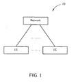
- FIG. 1 is a schematic diagram of a wireless communications system 10.
- the wireless communications system 10 is preferably a Long Term Evolution (LTE) communications system, and is briefly formed with a network terminal and a plurality of user equipments.
- LTE Long Term Evolution
- the network terminal and the user equipments are simply utilized for illustrating the structure of the wireless communications system 10.
- the network terminal may include a plurality of evolved Node Bs (eNBs), an evolved UMTS radio access network (E-UTRAN) etc.
- eNBs evolved Node Bs
- E-UTRAN evolved UMTS radio access network
- the user equipments can be apparatuses such as mobile phones, computer systems, etc.
- FIG. 2 is a functional block diagram of a communications device 200.
- the communications device 200 can be utilized for realizing the UEs in FIG. 1 .
- FIG. 2 only shows an input device 202, an output device 204, a control circuit 206, a processor 208, a storage device 210, a program 212, and a transceiver 214 of the communications device 200.
- the control circuit 206 executes the program 212 in the storage device 210 through the processor 208, thereby controlling an operation of the communications device 200.
- the communications device 200 can receive signals input by a user through the input device 202, such as a keyboard, and can output images and sounds through the output device 204, such as a monitor or speakers.
- the transceiver 214 is used to receive and transmit wireless signals, deliver received signals to the control circuit 206, and output signals generated by the control circuit 206 wirelessly. From a perspective of a communications protocol framework, the transceiver 214 can be seen as a portion of Layer 1, and the control circuit 206 can be utilized to realize functions of Layer 2 and Layer 3.
- FIG.3 is a diagram of the program 212 shown in FIG. 2 .
- the program 212 includes an application layer 300, a Layer 3 302, and a Layer 2 306, and is coupled to a Layer 1 308.
- the Layer 1 308 is utilized for realizing physical connections.
- the Layer 2 306 is utilized for realizing radio link control and medium access control.
- the Layer 3 302 is utilized for realizing radio resource control, and includes an RRC entity 304, which is used for controlling the Layer 1 218 and the Layer 2 206 and performing peer-to-peer RRC communication with other communications devices, such as a base station or a Node-B.
- the RRC entity 304 attempts to recover the connection with the network through the RRC connection re-establishment procedure if some connection problems are detected.
- a connection re-establishment program 320 is provided to assure that the RRC connection re-establishment procedure works well.
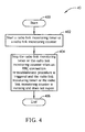
- FIG. 4 is a flowchart of a process 40 according to an embodiment of the present invention.
- the process 40 is used for connection re-establishment for a UE in a wireless communication system to avoid the connection malfunction caused by the RRC connection re-establishment procedure being repeatedly triggered.
- the process 40 can be compiled into the connection re-establishment program 320.
- the process 40 includes the following steps:
- an embodiment of the present invention stops the radio link monitoring timer or the radio link monitoring counter.
- the radio link monitoring timer is a timer T310.
- the radio link monitoring counter is used for counting the number of detections of the radio link problem.
- the RRC connection re-establishment procedure is triggered by a lower layer problem.
- the lower layer problem could be that the number of retransmission attempts of one RLC PDU exceeds the predefined value. Therefore, when the number of retransmission attempts of one RLC PDU exceeds the predefined value, and the radio link monitoring timer does not expire, according to an embodiment of the present invention, the UE stops the radio link monitoring timer or the radio link monitoring counter to avoid double-initiating the RRC connection re-establishment procedure due to expiry of the radio link monitoring timer.
- the UE stops the radio link monitoring timer or the radio link monitoring counter to avoid the connection malfunction caused by double-initiating the RRC connection re-establishment procedure.
Abstract
Description
- The present invention relates to a method and apparatus of connection re-establishment according to the pre-characterizing clauses of
claims 1 and 7. - Long Term Evolution wireless communications system (LTE system) is an advanced high-speed wireless communications system established upon the 3G mobile telecommunications system, that supports only packet-switched transmission, and tends to implement both Medium Access Control (MAC) layer and Radio Link Control (RLC) layer in one single communication site, such as in Node B alone rather than in Node B and RNC (Radio Network Controller) respectively, meaning the system structure becomes simple.
- In the LTE system, the Radio Resource Control (RRC) layer, a
Layer 3 protocol, is the core of communications protocols related to access stratum (AS) and is located in evolved Node B (eNB) of the Evolved UMTS Terrestrial Radio Access Network (E-UTRAN) and a user equipment (UE). The RRC layer uses RRC messages to perform RRC procedures. RRC messages are formed from many information elements (IEs) used for embedding necessary information for setting, changing, or releasing protocol entities ofLayer 2 andLayer 1, thereby establishing, adjusting, or canceling information exchange channels to perform data packet transportation. - Generally speaking, when the UE has established the connection with the network, the connection may encounter some problems under certain circumstances. At this point, the UE attempts to recover the connection with the network through an RRC connection re-establishment procedure. Thus, when the connection between the UE and the network does not work functionally, the LTE system defines the following situations which can trigger an RRC connection re-establishment procedure.
- (1) When radio link failure occurs, the UE re-establishes the connection with the network through the RRC connection re-establishment procedure.
- (2) When handover failure occurs, the UE attempts to re-establish the connection with the network.
- In addition, when the UE detects a physical layer radio link problem, the RRC layer starts a timer. If the physical layer radio link problem still exists when the timer expires, the RRC layer determines the radio link failure occurs. Generally, there are two other situations where the RRC layer determines the radio link failure occurs: (1) The MAC layer informs the RRC layer that random access problem occurs; (2) The RLC layer informs the RRC layer that a lower layer problem is detected. The lower layer problem is caused by the number of retransmission attempts of one RLC protocol data unit (PDU) exceeding a predefined value. As a result, the UE initiates the RRC connection re-establishment procedure.
- Nevertheless, when the radio link problems are detected by the physical layer, the RRC layer starts the timer to perform radio link monitoring. In the meantime, the UE may not be able to successfully transmit RLC PDUs due to the radio link problem, causing the number of retransmission attempts to exceed the predefined value. Consequently, the RRC layer determines the radio link failure occurs and initiates the RRC connection re-establishment procedure. Once the timer expires, another RRC connection re-establishment procedure is triggered. As a result, the previous RRC connection re-establishment procedure may be aborted or an unexpected problem may occur.
- To put it simply, the lower layer problem is detected prior to expiry of the timer, which triggers an RRC connection re-establishment procedure. Another RRC connection re-establishment is triggered when the timer expires. As a result, unexpected problem may occur, causing the connection malfunction.
- This in mind, the present invention aims at providing a method and apparatus of connection re-establishment, so as to avoid repeatedly triggering connection re-establishment procedure in a wireless communication system.
- This is achieved by a method and apparatus of connection re-establishment according to
claims 1 and 7. The dependent claims pertain to corresponding further developments and improvements. - As will be seen more clearly from the detailed description following below, the claimed method of connection re-establishment for a UE in a wireless communication system comprises starting a radio link monitoring timer or a radio link monitoring counter and stopping the radio link monitoring timer or the radio link monitoring counter when an RRC connection re-establishment procedure is triggered and the radio link monitoring timer or the radio link monitoring counter is running and does not expire.
-
-
FIG. 1 is a schematic diagram of a wireless communication system. -
FIG. 2 is a functional block diagram of a wireless communication device. -
FIG. 3 is a schematic diagram of the program shown inFIG.2 . -
FIG. 4 is a flowchart of a process according to an embodiment of the present invention. - Please refer to
FIG. 1 , which is a schematic diagram of awireless communications system 10. Thewireless communications system 10 is preferably a Long Term Evolution (LTE) communications system, and is briefly formed with a network terminal and a plurality of user equipments. InFIG. 1 , the network terminal and the user equipments are simply utilized for illustrating the structure of thewireless communications system 10. Practically, the network terminal may include a plurality of evolved Node Bs (eNBs), an evolved UMTS radio access network (E-UTRAN) etc. According to actual demands, and the user equipments (UEs) can be apparatuses such as mobile phones, computer systems, etc. - Please refer to
FIG. 2 , which is a functional block diagram of acommunications device 200. Thecommunications device 200 can be utilized for realizing the UEs inFIG. 1 . For the sake of brevity,FIG. 2 only shows aninput device 202, anoutput device 204, acontrol circuit 206, aprocessor 208, astorage device 210, aprogram 212, and atransceiver 214 of thecommunications device 200. In thecommunications device 200, thecontrol circuit 206 executes theprogram 212 in thestorage device 210 through theprocessor 208, thereby controlling an operation of thecommunications device 200. Thecommunications device 200 can receive signals input by a user through theinput device 202, such as a keyboard, and can output images and sounds through theoutput device 204, such as a monitor or speakers. Thetransceiver 214 is used to receive and transmit wireless signals, deliver received signals to thecontrol circuit 206, and output signals generated by thecontrol circuit 206 wirelessly. From a perspective of a communications protocol framework, thetransceiver 214 can be seen as a portion ofLayer 1, and thecontrol circuit 206 can be utilized to realize functions ofLayer 2 andLayer 3. - Please refer to
FIG.3 , which is a diagram of theprogram 212 shown inFIG. 2 . Theprogram 212 includes anapplication layer 300, aLayer 3 302, and aLayer 2 306, and is coupled to aLayer 1 308. TheLayer 1 308 is utilized for realizing physical connections. TheLayer 2 306 is utilized for realizing radio link control and medium access control. TheLayer 3 302 is utilized for realizing radio resource control, and includes anRRC entity 304, which is used for controlling theLayer 1 218 and theLayer 2 206 and performing peer-to-peer RRC communication with other communications devices, such as a base station or a Node-B. When thecommunication device 200 has established connection with the network, theRRC entity 304 attempts to recover the connection with the network through the RRC connection re-establishment procedure if some connection problems are detected. In this situation, according to an embodiment of the present invention, aconnection re-establishment program 320 is provided to assure that the RRC connection re-establishment procedure works well. - Please refer to
FIG. 4 , which is a flowchart of aprocess 40 according to an embodiment of the present invention. Theprocess 40 is used for connection re-establishment for a UE in a wireless communication system to avoid the connection malfunction caused by the RRC connection re-establishment procedure being repeatedly triggered. Theprocess 40 can be compiled into theconnection re-establishment program 320. Theprocess 40 includes the following steps: - Step 400: Start.
- Step 402: Start a radio link monitoring timer or a radio link monitoring counter.
- Step 404: Stop the radio link monitoring timer or the radio link monitoring counter when an RRC connection re-establishment procedure is triggered and the radio link monitoring timer or the radio link monitoring counter is running and does not expire.
- Step 406: End.
- According to the
process 40, when the RRC connection re-establishment procedure is triggered and the radio link monitoring timer or the radio link monitoring counter is still running and does not expire, an embodiment of the present invention stops the radio link monitoring timer or the radio link monitoring counter. Preferably, the radio link monitoring timer is a timer T310. The radio link monitoring counter is used for counting the number of detections of the radio link problem. As a result, the connection malfunction, for example, the previous RRC connection re-establishment procedure may be aborted and double-initiating of the RRC connection re-establishment procedure due to expiry of the radio link monitoring timer can be avoided. - Preferably, the RRC connection re-establishment procedure is triggered by a lower layer problem. The lower layer problem could be that the number of retransmission attempts of one RLC PDU exceeds the predefined value. Therefore, when the number of retransmission attempts of one RLC PDU exceeds the predefined value, and the radio link monitoring timer does not expire, according to an embodiment of the present invention, the UE stops the radio link monitoring timer or the radio link monitoring counter to avoid double-initiating the RRC connection re-establishment procedure due to expiry of the radio link monitoring timer.
- To sum up, according to an embodiment of the present invention, when the RRC connection re-establishment procedure is triggered and the radio link monitoring timer or the radio link monitoring counter is running and does not expire, the UE stops the radio link monitoring timer or the radio link monitoring counter to avoid the connection malfunction caused by double-initiating the RRC connection re-establishment procedure.
Claims (12)
- A method of connection re-establishment for a user equipment in a wireless communication system (10), the method comprising:starting a radio link monitoring timer or a radio link monitoring counter (402); andcharacterized by:stopping the radio link monitoring timer or the radio link monitoring counter when a radio resource control, hereinafter called RRC, connection re-establishment procedure is triggered and the radio link monitoring timer or the radio link monitoring counter is running and does not expire (404).
- The method of claim 1, characterized in that the RRC connection re-establishment procedure is triggered by a lower layer problem.
- The method of claim 2, characterized in that the lower layer problem is that the number of retransmission attempts of a Radio Link Control Protocol Data Unit, hereinafter called RLC PDU, exceeds a predefined value.
- The method of claim 1, characterized in that the radio link monitoring timer is a timer T310.
- The method of claim 1, characterized in that the radio link monitoring counter is used for counting the number of detections of a radio link problem.
- The method of claim 1, characterized in that the method further comprises resetting the radio link monitoring counter.
- A communication device (200) of a user equipment in a wireless communication system (10) for connection re-establishment, the communication device (200) comprising:a processor (208) for executing a process; anda storage device (210), coupled to the processor (208), for storing a program (212) for executing the process, wherein the process comprises:starting a radio link monitoring timer or a radio link monitoring counter (402); andcharacterized by:stopping the radio link monitoring timer or the radio link monitoring counter when a radio resource control, hereinafter called RRC, connection re-establishment procedure is triggered and the radio link monitoring timer or the radio link monitoring counter is running and does not expire (404).
- The communication device (200) of claim 7, characterized in that the RRC connection re-establishment procedure is triggered by a lower layer problem.
- The communication device (200) of claim 8, characterized in that the lower layer problem is that the number of retransmission attempts of a Radio Link Control Protocol Data Unit (RLC PDU) exceeds a predefined value.
- The communication device (200) of claim 7, characterized in that the radio link monitoring timer is a timer T310.
- The communication device (200) of claim 7, characterized in that the radio link monitoring counter is used for counting the number of detections of a radio link problem.
- The communication device (200) of claim 7, characterized in that the process further comprises resetting the radio link monitoring counter.
Applications Claiming Priority (1)
| Application Number | Priority Date | Filing Date | Title |
|---|---|---|---|
| US5446608P | 2008-05-19 | 2008-05-19 |
Publications (2)
| Publication Number | Publication Date |
|---|---|
| EP2124502A1 EP2124502A1 (en) | 2009-11-25 |
| EP2124502B1 true EP2124502B1 (en) | 2011-04-13 |
Family
ID=40902147
Family Applications (2)
| Application Number | Title | Priority Date | Filing Date |
|---|---|---|---|
| EP09005422A Revoked EP2124499B1 (en) | 2008-05-19 | 2009-04-16 | Method and apparatus for performing buffer status reporting (BSR) |
| EP09005735A Active EP2124502B1 (en) | 2008-05-19 | 2009-04-23 | Method of connection re-establishment and related communication device |
Family Applications Before (1)
| Application Number | Title | Priority Date | Filing Date |
|---|---|---|---|
| EP09005422A Revoked EP2124499B1 (en) | 2008-05-19 | 2009-04-16 | Method and apparatus for performing buffer status reporting (BSR) |
Country Status (9)
| Country | Link |
|---|---|
| US (2) | US8031658B2 (en) |
| EP (2) | EP2124499B1 (en) |
| JP (2) | JP4976440B2 (en) |
| KR (2) | KR101035875B1 (en) |
| CN (2) | CN101588227B (en) |
| AT (2) | ATE478537T1 (en) |
| DE (2) | DE602009000120D1 (en) |
| ES (2) | ES2350565T3 (en) |
| TW (2) | TWI397337B (en) |
Families Citing this family (32)
| Publication number | Priority date | Publication date | Assignee | Title |
|---|---|---|---|---|
| KR101660983B1 (en) * | 2009-04-13 | 2016-09-28 | 엘지전자 주식회사 | Method of configuring radio resource by a mac layer of terminal in a wireless communication system |
| CN102111808B (en) * | 2009-12-25 | 2012-04-25 | 华为技术有限公司 | Method and device for reporting buffer status |
| US20110194630A1 (en) * | 2010-02-10 | 2011-08-11 | Yang Hua-Lung | Systems and methods for reporting radio link failure |
| CN102202405B (en) * | 2010-03-23 | 2014-04-30 | 中兴通讯股份有限公司 | Method and device for allocating wireless resource during switching |
| KR101887062B1 (en) * | 2010-04-01 | 2018-08-09 | 엘지전자 주식회사 | Signal processing method in wireless communication system and device therefor |
| KR101831281B1 (en) | 2010-04-06 | 2018-02-23 | 삼성전자주식회사 | Device and method for handling scheduling information in wireless communication system |
| US9258088B2 (en) * | 2010-06-18 | 2016-02-09 | Acer Incorporated | Method of performing buffer status reporting and communication device thereof |
| US9924412B2 (en) | 2010-06-18 | 2018-03-20 | Acer Incorporated | Method of handling buffer status report and communication device thereof |
| KR101730778B1 (en) | 2010-06-18 | 2017-04-26 | 후지쯔 가부시끼가이샤 | Reporting method of terminal buffer state report(bsr), obtaining method for obtaining bsr from base station, and corresponding terminal, base station, communication system |
| WO2014071599A1 (en) * | 2012-11-09 | 2014-05-15 | Nokia Corporation | Methods and apparatuses of radio resource control connection recovery |
| EP2765731B1 (en) * | 2012-12-24 | 2021-06-16 | Innovative Sonic Corporation | Methods and apparatus of small cell enhancement in a wireless communication system |
| EP2958387B1 (en) * | 2013-03-12 | 2017-08-16 | Huawei Technologies Co., Ltd. | Data transmission processing method and device |
| US9838158B2 (en) | 2013-07-17 | 2017-12-05 | Lg Electronics Inc. | Method for reporting a radio link control re-transmission failure and a device therefor |
| EP3120607B1 (en) | 2014-03-19 | 2019-09-11 | LG Electronics Inc. | Method and apparatus for configuring buffer status report for public safety transmission in wireless communication system |
| US10165572B2 (en) | 2014-03-19 | 2018-12-25 | Lg Electronics Inc. | Method and apparatus for canceling triggered buffer status report for device-to-device transmission in wireless communication system |
| US9955445B2 (en) * | 2014-04-01 | 2018-04-24 | Samsung Electronics Co., Ltd | System and method for enhancing reporting information for radio link failure (RLF) in LTE networks |
| US10536948B2 (en) * | 2015-06-22 | 2020-01-14 | Qualcomm Incorporated | Methods and apparatus for requesting buffer status reports for implementing multiple user uplink medium access control protocols in a wireless network |
| CN106412794B (en) * | 2015-07-21 | 2020-01-07 | 电信科学技术研究院 | Resource allocation method and equipment |
| CA2998304C (en) * | 2015-09-18 | 2023-09-12 | Sharp Kabushiki Kaisha | Terminal device, base station device, communication method, and integrated circuit |
| US9942898B2 (en) * | 2016-04-25 | 2018-04-10 | Ofinno Technologies, Llc | Uplink transmission in a wireless device and wireless network |
| WO2018027904A1 (en) * | 2016-08-12 | 2018-02-15 | Mediatek Singapore Pte. Ltd | Methods and apparatus for handling of radio link failure detection in hf-nr system |
| US10863380B2 (en) | 2017-03-16 | 2020-12-08 | Ofinno, Llc | Buffer status reporting procedure in a wireless device and wireless network |
| US10856174B2 (en) | 2017-03-16 | 2020-12-01 | Ofinno, Llc | Buffer status report control |
| KR102326369B1 (en) | 2017-03-16 | 2021-11-15 | 베이징 시아오미 모바일 소프트웨어 컴퍼니 리미티드 | Report truncated buffer status |
| WO2018213166A1 (en) * | 2017-05-15 | 2018-11-22 | Kyocera Corporation | Method of radio link monitoring for mtc with coverage enhancement |
| CN111886891B (en) * | 2018-01-11 | 2024-02-06 | 株式会社Ntt都科摩 | User terminal and wireless communication method |
| JP6658784B2 (en) * | 2018-03-15 | 2020-03-04 | 富士通株式会社 | Buffer status report reporting method, acquisition method, terminal, base station, and communication system |
| WO2019222884A1 (en) | 2018-05-21 | 2019-11-28 | 北京小米移动软件有限公司 | Method and apparatus for setting format of buffer status report |
| KR20230125103A (en) | 2019-05-31 | 2023-08-28 | 구글 엘엘씨 | Method for operating a bluetooth device |
| EP3745813A1 (en) | 2019-05-31 | 2020-12-02 | Tap Sound System | Method for operating a bluetooth device |
| EP4114052B1 (en) | 2019-07-26 | 2023-12-20 | Google LLC | Method for managing a plurality of multimedia communication links in a point-to-multipoint bluetooth network |
| EP4018772B1 (en) * | 2019-08-21 | 2023-11-22 | Lenovo (Singapore) Pte. Ltd. | Radio link failure recovery |
Family Cites Families (38)
| Publication number | Priority date | Publication date | Assignee | Title |
|---|---|---|---|---|
| FI110352B (en) * | 2000-02-24 | 2002-12-31 | Nokia Corp | Method and arrangement to optimize the re-establishment of connections in a cellular radio system that supports real-time and non-real-time communications |
| US7187930B2 (en) * | 2000-11-28 | 2007-03-06 | Denso Corporation | Retry limits for connection rescue procedures in telecommunication systems |
| US20030206534A1 (en) * | 2002-05-03 | 2003-11-06 | Wu Frank Chih-Hsiang | Scheme to handle radio link control service data units upon reception of a radio link control reset or reset acknowledge protocol data unit in a wireless communication system |
| US20040203623A1 (en) * | 2002-05-03 | 2004-10-14 | Wu Frank Chih-Hsiang | Scheme to retransmit radio resource control messages during a radio link control reset in a wireless communication system |
| US6961570B2 (en) | 2002-07-17 | 2005-11-01 | Asustek Computer Inc. | Handling of a wireless device re-entering a service area |
| US7227856B2 (en) | 2002-08-13 | 2007-06-05 | Innovative Sonic Limited | Method for handling timers after an RLC reset or re-establishment in a wireless communications system |
| US20040185855A1 (en) | 2002-12-31 | 2004-09-23 | Storm Brian D. | Method and apparatus for continuing a call |
| EP1465369A1 (en) | 2003-03-31 | 2004-10-06 | Matsushita Electric Industrial Co., Ltd. | Reset synchronisation method for a retransmission protocol |
| US7512112B2 (en) * | 2003-08-15 | 2009-03-31 | Innovative Sonic Limited | Method and apparatus of controlling a reset procedure in a wireless communication system |
| KR100678179B1 (en) * | 2004-05-12 | 2007-02-02 | 삼성전자주식회사 | Apparatus and method for recovering a dropped communication link in mobile communication system |
| US7525908B2 (en) * | 2004-09-24 | 2009-04-28 | M-Stack Limited | Data unit management in communications |
| US8189615B2 (en) | 2004-12-23 | 2012-05-29 | Nokia Corporation | Method and apparatus for communicating scheduling information from a UE to a radio access network |
| US20060209684A1 (en) * | 2005-03-18 | 2006-09-21 | Via Technologies, Inc. | Data rate controller, and method of control thereof |
| JP4577505B2 (en) * | 2005-03-31 | 2010-11-10 | 日本電気株式会社 | Method for contention relief between downlink RRC message and inter-cell movement of mobile station in mobile communication system |
| KR100770863B1 (en) * | 2005-04-04 | 2007-10-26 | 삼성전자주식회사 | Method and apparatus for reporming buffer status reporting by using node b estimated buffer status information in a mobile telecommunication system |
| US7821975B2 (en) | 2005-06-10 | 2010-10-26 | Motorola, Inc. | Establishing radio link control in wireless communication networks |
| TWI398118B (en) * | 2005-09-21 | 2013-06-01 | Innovative Sonic Ltd | Method and apparatus for handling control pdus during re-establishing transmitting sides in a wireless communications system |
| US20070104109A1 (en) * | 2005-11-04 | 2007-05-10 | Innovative Sonic Limited | Method and apparatus for RLC protocol error handling in a wireless communications system |
| AU2007203852B2 (en) * | 2006-01-05 | 2010-08-26 | Lg Electronics Inc. | Transmitting data in a mobile communication system |
| KR100754612B1 (en) | 2006-01-26 | 2007-09-05 | 삼성전자주식회사 | Handover method for minimizing delay time according to reconnecting of packet call between two mobile communication modes and the multi-mode terminal therefor |
| TWI387250B (en) | 2006-05-03 | 2013-02-21 | Innovative Sonic Ltd | Method and apparatus of handling variable of rlc reset procedure during receiver-side-only re-establishment in wireless communications system |
| BRPI0710322A2 (en) * | 2006-05-05 | 2011-08-09 | Interdigital Tech Corp | long-link up and down link radio link failure detection procedures and apparatus for this procedure |
| CN102655657A (en) * | 2006-05-07 | 2012-09-05 | 创新音速有限公司 | Method and related apparatus of default timer configurations of a wireless communications system |
| BRPI0621815B8 (en) | 2006-06-21 | 2019-11-05 | Ericsson Telefon Ab L M | method for reporting scheduling information processed on user equipment of a wireless communication system, and user equipment on a wireless communication system |
| US20080056148A1 (en) * | 2006-09-06 | 2008-03-06 | Mediatek Inc. | Wireless communication method and apparatus for reducing data retransmission |
| JP2008079311A (en) * | 2006-09-21 | 2008-04-03 | Asustek Computer Inc | Method and apparatus for detecting radio link failure in wireless communication system |
| TW200822613A (en) * | 2006-11-07 | 2008-05-16 | Innovative Sonic Ltd | Method and apparatus for performing uplink transmission in a multi-input multi-output user equipment of a wireless communications system |
| JP5231550B2 (en) * | 2007-08-13 | 2013-07-10 | エルジー エレクトロニクス インコーポレイティド | Method for transmitting VoIP packets |
| WO2009040773A2 (en) * | 2007-09-28 | 2009-04-02 | Nokia Siemens Networks Oy | Method and apparatus for signaling of scheduling information |
| US20090190480A1 (en) | 2007-12-11 | 2009-07-30 | Interdigital Patent Holdings, Inc. | Methods and apparatus for detecting radio link control protocol errors and triggering radio link control re-establishment |
| US9215731B2 (en) * | 2007-12-19 | 2015-12-15 | Qualcomm Incorporated | Method and apparatus for transfer of a message on a common control channel for random access in a wireless communication network |
| WO2009088710A1 (en) * | 2008-01-04 | 2009-07-16 | Interdigital Patent Holdings, Inc. | Method and apparatus of performing packet data convergence protocol re-establishment |
| US20090175175A1 (en) * | 2008-01-04 | 2009-07-09 | Interdigital Patent Holdings, Inc. | Radio link control reset using radio resource control signaling |
| WO2009096883A1 (en) * | 2008-01-18 | 2009-08-06 | Telefonaktiebolaget L M Ericsson (Publ) | Method and apparatus for radio link failure recovery in a telecommunication system |
| WO2009096847A1 (en) * | 2008-01-30 | 2009-08-06 | Telefonaktiebolaget L M Ericsson (Publ) | Method and arrangement in a telecommunication system |
| EP2094039B1 (en) * | 2008-02-20 | 2016-11-09 | Amazon Technologies, Inc. | Method and apparatus for processing padding buffer status reports |
| US8306059B2 (en) * | 2008-11-05 | 2012-11-06 | Htc Corporation | Method of constructing and transmitting packets with MIMO configuration in a wireless communication system and related communication device |
| US8284732B2 (en) * | 2009-02-03 | 2012-10-09 | Motorola Mobility Llc | Method and apparatus for transport block signaling in a wireless communication system |
-
2009
- 2009-03-25 JP JP2009073452A patent/JP4976440B2/en active Active
- 2009-04-02 KR KR1020090028586A patent/KR101035875B1/en active IP Right Grant
- 2009-04-16 DE DE602009000120T patent/DE602009000120D1/en active Active
- 2009-04-16 US US12/424,548 patent/US8031658B2/en active Active
- 2009-04-16 ES ES09005422T patent/ES2350565T3/en active Active
- 2009-04-16 AT AT09005422T patent/ATE478537T1/en not_active IP Right Cessation
- 2009-04-16 EP EP09005422A patent/EP2124499B1/en not_active Revoked
- 2009-04-23 US US12/429,180 patent/US8553569B2/en active Active
- 2009-04-23 EP EP09005735A patent/EP2124502B1/en active Active
- 2009-04-23 AT AT09005735T patent/ATE505931T1/en not_active IP Right Cessation
- 2009-04-23 DE DE602009001043T patent/DE602009001043D1/en active Active
- 2009-04-23 ES ES09005735T patent/ES2363926T3/en active Active
- 2009-05-01 KR KR1020090038684A patent/KR101086683B1/en active IP Right Grant
- 2009-05-07 JP JP2009113081A patent/JP4932870B2/en active Active
- 2009-05-19 TW TW098116542A patent/TWI397337B/en active
- 2009-05-19 CN CN2009102030640A patent/CN101588227B/en active Active
- 2009-05-19 TW TW098116541A patent/TWI392393B/en active
- 2009-05-19 CN CN200910203066XA patent/CN101588638B/en active Active
Also Published As
| Publication number | Publication date |
|---|---|
| EP2124502A1 (en) | 2009-11-25 |
| EP2124499A1 (en) | 2009-11-25 |
| TW201014426A (en) | 2010-04-01 |
| KR101035875B1 (en) | 2011-05-20 |
| TWI397337B (en) | 2013-05-21 |
| JP4976440B2 (en) | 2012-07-18 |
| US20090285111A1 (en) | 2009-11-19 |
| US20090285104A1 (en) | 2009-11-19 |
| CN101588638B (en) | 2012-01-11 |
| JP2009284469A (en) | 2009-12-03 |
| ATE505931T1 (en) | 2011-04-15 |
| KR101086683B1 (en) | 2011-11-24 |
| KR20090120399A (en) | 2009-11-24 |
| CN101588638A (en) | 2009-11-25 |
| ES2350565T3 (en) | 2011-01-25 |
| JP2009284479A (en) | 2009-12-03 |
| KR20090120403A (en) | 2009-11-24 |
| EP2124499B1 (en) | 2010-08-18 |
| CN101588227A (en) | 2009-11-25 |
| DE602009001043D1 (en) | 2011-05-26 |
| JP4932870B2 (en) | 2012-05-16 |
| TW200950563A (en) | 2009-12-01 |
| ES2363926T3 (en) | 2011-08-19 |
| TWI392393B (en) | 2013-04-01 |
| CN101588227B (en) | 2013-06-12 |
| DE602009000120D1 (en) | 2010-09-30 |
| US8031658B2 (en) | 2011-10-04 |
| US8553569B2 (en) | 2013-10-08 |
| ATE478537T1 (en) | 2010-09-15 |
Similar Documents
| Publication | Publication Date | Title |
|---|---|---|
| EP2124502B1 (en) | Method of connection re-establishment and related communication device | |
| EP2278836B1 (en) | Method and apparatus for handling inter-RAT handover | |
| EP2094053A1 (en) | Method and apparatus for improving random access procedure for handover | |
| EP2101531B1 (en) | Method and apparatus for handling a contention-based random acces procedure | |
| JP4926216B2 (en) | Method and communication apparatus for processing uplink grant | |
| EP2056635A1 (en) | Method of handling random access procedure failure and related communication device | |
| US20100302951A1 (en) | Method and Apparatus for Handling Radio Link Failure | |
| JP4577505B2 (en) | Method for contention relief between downlink RRC message and inter-cell movement of mobile station in mobile communication system | |
| EP2107851B1 (en) | Establishing radio link control in wireless communication networks | |
| EP2227053B1 (en) | Method for improving buffer status triggering mechanism in wireless communications system and related communication device | |
| EP2131624A1 (en) | Method and apparatus for handling semi-persistent transmission resource | |
| EP3592097B1 (en) | Radio link failure handling method and related product | |
| EP2282598B1 (en) | Method and apparatus for handling physical downlink control channel orders in wireless communication system | |
| EP2309818A1 (en) | Method and apparatus for handling radio link failure in wireless communication system | |
| EP2139285A2 (en) | Method and apparatus for handling handover procedure | |
| EP2111081B1 (en) | Method and apparatus for improving RRC connection procedure | |
| CN112788797B (en) | Method and apparatus for releasing pre-configured uplink resource (PUR) in wireless communication system | |
| EP1855409B1 (en) | Method and related apparatus of default timer configurations of a wireless communications system | |
| EP2063680B1 (en) | Enhancing radio resource control (RRC) procedure re-initiation efficiency in a wireless communications system | |
| WO2013079036A1 (en) | Resource-release control method and access device |
Legal Events
| Date | Code | Title | Description |
|---|---|---|---|
| PUAI | Public reference made under article 153(3) epc to a published international application that has entered the european phase |
Free format text: ORIGINAL CODE: 0009012 |
|
| 17P | Request for examination filed |
Effective date: 20090423 |
|
| AK | Designated contracting states |
Kind code of ref document: A1 Designated state(s): AT BE BG CH CY CZ DE DK EE ES FI FR GB GR HR HU IE IS IT LI LT LU LV MC MK MT NL NO PL PT RO SE SI SK TR |
|
| GRAP | Despatch of communication of intention to grant a patent |
Free format text: ORIGINAL CODE: EPIDOSNIGR1 |
|
| RIC1 | Information provided on ipc code assigned before grant |
Ipc: H04W 76/04 20090101AFI20101014BHEP |
|
| RIN1 | Information on inventor provided before grant (corrected) |
Inventor name: OU, MENG-HUI |
|
| GRAS | Grant fee paid |
Free format text: ORIGINAL CODE: EPIDOSNIGR3 |
|
| GRAA | (expected) grant |
Free format text: ORIGINAL CODE: 0009210 |
|
| AK | Designated contracting states |
Kind code of ref document: B1 Designated state(s): AT BE BG CH CY CZ DE DK EE ES FI FR GB GR HR HU IE IS IT LI LT LU LV MC MK MT NL NO PL PT RO SE SI SK TR |
|
| REG | Reference to a national code |
Ref country code: GB Ref legal event code: FG4D |
|
| REG | Reference to a national code |
Ref country code: CH Ref legal event code: EP |
|
| REG | Reference to a national code |
Ref country code: IE Ref legal event code: FG4D |
|
| REG | Reference to a national code |
Ref country code: NL Ref legal event code: T3 |
|
| REF | Corresponds to: |
Ref document number: 602009001043 Country of ref document: DE Date of ref document: 20110526 Kind code of ref document: P |
|
| REG | Reference to a national code |
Ref country code: DE Ref legal event code: R096 Ref document number: 602009001043 Country of ref document: DE Effective date: 20110526 |
|
| REG | Reference to a national code |
Ref country code: SE Ref legal event code: TRGR |
|
| REG | Reference to a national code |
Ref country code: ES Ref legal event code: FG2A Ref document number: 2363926 Country of ref document: ES Kind code of ref document: T3 Effective date: 20110819 |
|
| LTIE | Lt: invalidation of european patent or patent extension |
Effective date: 20110413 |
|
| PG25 | Lapsed in a contracting state [announced via postgrant information from national office to epo] |
Ref country code: NO Free format text: LAPSE BECAUSE OF FAILURE TO SUBMIT A TRANSLATION OF THE DESCRIPTION OR TO PAY THE FEE WITHIN THE PRESCRIBED TIME-LIMIT Effective date: 20110713 Ref country code: LT Free format text: LAPSE BECAUSE OF FAILURE TO SUBMIT A TRANSLATION OF THE DESCRIPTION OR TO PAY THE FEE WITHIN THE PRESCRIBED TIME-LIMIT Effective date: 20110413 Ref country code: HR Free format text: LAPSE BECAUSE OF FAILURE TO SUBMIT A TRANSLATION OF THE DESCRIPTION OR TO PAY THE FEE WITHIN THE PRESCRIBED TIME-LIMIT Effective date: 20110413 Ref country code: PT Free format text: LAPSE BECAUSE OF FAILURE TO SUBMIT A TRANSLATION OF THE DESCRIPTION OR TO PAY THE FEE WITHIN THE PRESCRIBED TIME-LIMIT Effective date: 20110816 |
|
| PG25 | Lapsed in a contracting state [announced via postgrant information from national office to epo] |
Ref country code: IS Free format text: LAPSE BECAUSE OF FAILURE TO SUBMIT A TRANSLATION OF THE DESCRIPTION OR TO PAY THE FEE WITHIN THE PRESCRIBED TIME-LIMIT Effective date: 20110813 Ref country code: MC Free format text: LAPSE BECAUSE OF NON-PAYMENT OF DUE FEES Effective date: 20110430 Ref country code: AT Free format text: LAPSE BECAUSE OF FAILURE TO SUBMIT A TRANSLATION OF THE DESCRIPTION OR TO PAY THE FEE WITHIN THE PRESCRIBED TIME-LIMIT Effective date: 20110413 Ref country code: BE Free format text: LAPSE BECAUSE OF FAILURE TO SUBMIT A TRANSLATION OF THE DESCRIPTION OR TO PAY THE FEE WITHIN THE PRESCRIBED TIME-LIMIT Effective date: 20110413 Ref country code: LV Free format text: LAPSE BECAUSE OF FAILURE TO SUBMIT A TRANSLATION OF THE DESCRIPTION OR TO PAY THE FEE WITHIN THE PRESCRIBED TIME-LIMIT Effective date: 20110413 Ref country code: CY Free format text: LAPSE BECAUSE OF FAILURE TO SUBMIT A TRANSLATION OF THE DESCRIPTION OR TO PAY THE FEE WITHIN THE PRESCRIBED TIME-LIMIT Effective date: 20110413 Ref country code: GR Free format text: LAPSE BECAUSE OF FAILURE TO SUBMIT A TRANSLATION OF THE DESCRIPTION OR TO PAY THE FEE WITHIN THE PRESCRIBED TIME-LIMIT Effective date: 20110714 Ref country code: SI Free format text: LAPSE BECAUSE OF FAILURE TO SUBMIT A TRANSLATION OF THE DESCRIPTION OR TO PAY THE FEE WITHIN THE PRESCRIBED TIME-LIMIT Effective date: 20110413 |
|
| PG25 | Lapsed in a contracting state [announced via postgrant information from national office to epo] |
Ref country code: MT Free format text: LAPSE BECAUSE OF FAILURE TO SUBMIT A TRANSLATION OF THE DESCRIPTION OR TO PAY THE FEE WITHIN THE PRESCRIBED TIME-LIMIT Effective date: 20110413 |
|
| PG25 | Lapsed in a contracting state [announced via postgrant information from national office to epo] |
Ref country code: EE Free format text: LAPSE BECAUSE OF FAILURE TO SUBMIT A TRANSLATION OF THE DESCRIPTION OR TO PAY THE FEE WITHIN THE PRESCRIBED TIME-LIMIT Effective date: 20110413 Ref country code: CZ Free format text: LAPSE BECAUSE OF FAILURE TO SUBMIT A TRANSLATION OF THE DESCRIPTION OR TO PAY THE FEE WITHIN THE PRESCRIBED TIME-LIMIT Effective date: 20110413 |
|
| REG | Reference to a national code |
Ref country code: IE Ref legal event code: MM4A |
|
| PLBE | No opposition filed within time limit |
Free format text: ORIGINAL CODE: 0009261 |
|
| STAA | Information on the status of an ep patent application or granted ep patent |
Free format text: STATUS: NO OPPOSITION FILED WITHIN TIME LIMIT |
|
| PG25 | Lapsed in a contracting state [announced via postgrant information from national office to epo] |
Ref country code: PL Free format text: LAPSE BECAUSE OF FAILURE TO SUBMIT A TRANSLATION OF THE DESCRIPTION OR TO PAY THE FEE WITHIN THE PRESCRIBED TIME-LIMIT Effective date: 20110413 Ref country code: DK Free format text: LAPSE BECAUSE OF FAILURE TO SUBMIT A TRANSLATION OF THE DESCRIPTION OR TO PAY THE FEE WITHIN THE PRESCRIBED TIME-LIMIT Effective date: 20110413 Ref country code: RO Free format text: LAPSE BECAUSE OF FAILURE TO SUBMIT A TRANSLATION OF THE DESCRIPTION OR TO PAY THE FEE WITHIN THE PRESCRIBED TIME-LIMIT Effective date: 20110413 Ref country code: SK Free format text: LAPSE BECAUSE OF FAILURE TO SUBMIT A TRANSLATION OF THE DESCRIPTION OR TO PAY THE FEE WITHIN THE PRESCRIBED TIME-LIMIT Effective date: 20110413 |
|
| 26N | No opposition filed |
Effective date: 20120116 |
|
| PG25 | Lapsed in a contracting state [announced via postgrant information from national office to epo] |
Ref country code: IE Free format text: LAPSE BECAUSE OF NON-PAYMENT OF DUE FEES Effective date: 20110423 |
|
| REG | Reference to a national code |
Ref country code: DE Ref legal event code: R097 Ref document number: 602009001043 Country of ref document: DE Effective date: 20120116 |
|
| PG25 | Lapsed in a contracting state [announced via postgrant information from national office to epo] |
Ref country code: MK Free format text: LAPSE BECAUSE OF FAILURE TO SUBMIT A TRANSLATION OF THE DESCRIPTION OR TO PAY THE FEE WITHIN THE PRESCRIBED TIME-LIMIT Effective date: 20110413 |
|
| PG25 | Lapsed in a contracting state [announced via postgrant information from national office to epo] |
Ref country code: LU Free format text: LAPSE BECAUSE OF NON-PAYMENT OF DUE FEES Effective date: 20110423 |
|
| PG25 | Lapsed in a contracting state [announced via postgrant information from national office to epo] |
Ref country code: BG Free format text: LAPSE BECAUSE OF FAILURE TO SUBMIT A TRANSLATION OF THE DESCRIPTION OR TO PAY THE FEE WITHIN THE PRESCRIBED TIME-LIMIT Effective date: 20110713 |
|
| PG25 | Lapsed in a contracting state [announced via postgrant information from national office to epo] |
Ref country code: TR Free format text: LAPSE BECAUSE OF FAILURE TO SUBMIT A TRANSLATION OF THE DESCRIPTION OR TO PAY THE FEE WITHIN THE PRESCRIBED TIME-LIMIT Effective date: 20110413 |
|
| PG25 | Lapsed in a contracting state [announced via postgrant information from national office to epo] |
Ref country code: HU Free format text: LAPSE BECAUSE OF FAILURE TO SUBMIT A TRANSLATION OF THE DESCRIPTION OR TO PAY THE FEE WITHIN THE PRESCRIBED TIME-LIMIT Effective date: 20110413 |
|
| REG | Reference to a national code |
Ref country code: CH Ref legal event code: PL |
|
| PG25 | Lapsed in a contracting state [announced via postgrant information from national office to epo] |
Ref country code: CH Free format text: LAPSE BECAUSE OF NON-PAYMENT OF DUE FEES Effective date: 20130430 Ref country code: LI Free format text: LAPSE BECAUSE OF NON-PAYMENT OF DUE FEES Effective date: 20130430 |
|
| REG | Reference to a national code |
Ref country code: DE Ref legal event code: R082 Ref document number: 602009001043 Country of ref document: DE Representative=s name: HOEFER & PARTNER, DE |
|
| REG | Reference to a national code |
Ref country code: DE Ref legal event code: R082 Ref document number: 602009001043 Country of ref document: DE Representative=s name: HOEFER & PARTNER, DE |
|
| REG | Reference to a national code |
Ref country code: DE Ref legal event code: R082 Ref document number: 602009001043 Country of ref document: DE Representative=s name: HOEFER & PARTNER, DE Effective date: 20140604 Ref country code: DE Ref legal event code: R081 Ref document number: 602009001043 Country of ref document: DE Owner name: INNOVATIVE SONIC LIMITED, MU Free format text: FORMER OWNER: INNOVATIVE SONIC LTD., ROAD TOWN, TORTOLA, VG Effective date: 20140604 Ref country code: DE Ref legal event code: R082 Ref document number: 602009001043 Country of ref document: DE Representative=s name: HOEFER & PARTNER, DE Effective date: 20140610 Ref country code: DE Ref legal event code: R081 Ref document number: 602009001043 Country of ref document: DE Owner name: INNOVATIVE SONIC LIMITED, MU Free format text: FORMER OWNER: INNOVATIVE SONIC LIMITED, PORT LOUIS, MU Effective date: 20140610 Ref country code: DE Ref legal event code: R082 Ref document number: 602009001043 Country of ref document: DE Representative=s name: HOEFER & PARTNER PATENTANWAELTE MBB, DE Effective date: 20140604 Ref country code: DE Ref legal event code: R082 Ref document number: 602009001043 Country of ref document: DE Representative=s name: HOEFER & PARTNER PATENTANWAELTE MBB, DE Effective date: 20140610 |
|
| REG | Reference to a national code |
Ref country code: FR Ref legal event code: CA Effective date: 20150312 |
|
| REG | Reference to a national code |
Ref country code: FR Ref legal event code: PLFP Year of fee payment: 8 |
|
| REG | Reference to a national code |
Ref country code: FR Ref legal event code: PLFP Year of fee payment: 9 |
|
| REG | Reference to a national code |
Ref country code: DE Ref legal event code: R079 Ref document number: 602009001043 Country of ref document: DE Free format text: PREVIOUS MAIN CLASS: H04W0076040000 Ipc: H04W0076200000 |
|
| REG | Reference to a national code |
Ref country code: FR Ref legal event code: PLFP Year of fee payment: 10 |
|
| PGFP | Annual fee paid to national office [announced via postgrant information from national office to epo] |
Ref country code: FR Payment date: 20230317 Year of fee payment: 15 |
|
| PGFP | Annual fee paid to national office [announced via postgrant information from national office to epo] |
Ref country code: SE Payment date: 20230314 Year of fee payment: 15 Ref country code: GB Payment date: 20230317 Year of fee payment: 15 |
|
| P01 | Opt-out of the competence of the unified patent court (upc) registered |
Effective date: 20230508 |
|
| PGFP | Annual fee paid to national office [announced via postgrant information from national office to epo] |
Ref country code: NL Payment date: 20230424 Year of fee payment: 15 |
|
| PGFP | Annual fee paid to national office [announced via postgrant information from national office to epo] |
Ref country code: IT Payment date: 20230421 Year of fee payment: 15 Ref country code: ES Payment date: 20230505 Year of fee payment: 15 Ref country code: DE Payment date: 20230316 Year of fee payment: 15 |
|
| PGFP | Annual fee paid to national office [announced via postgrant information from national office to epo] |
Ref country code: FI Payment date: 20230424 Year of fee payment: 15 |