EP2124478A1 - Delay time calculation apparatus, delay time calculation method, and storage medium storing program therefor - Google Patents
Delay time calculation apparatus, delay time calculation method, and storage medium storing program therefor Download PDFInfo
- Publication number
- EP2124478A1 EP2124478A1 EP09006619A EP09006619A EP2124478A1 EP 2124478 A1 EP2124478 A1 EP 2124478A1 EP 09006619 A EP09006619 A EP 09006619A EP 09006619 A EP09006619 A EP 09006619A EP 2124478 A1 EP2124478 A1 EP 2124478A1
- Authority
- EP
- European Patent Office
- Prior art keywords
- delay time
- speaker
- speaker units
- time calculation
- area
- Prior art date
- Legal status (The legal status is an assumption and is not a legal conclusion. Google has not performed a legal analysis and makes no representation as to the accuracy of the status listed.)
- Granted
Links
Images



Classifications
-
- H—ELECTRICITY
- H04—ELECTRIC COMMUNICATION TECHNIQUE
- H04R—LOUDSPEAKERS, MICROPHONES, GRAMOPHONE PICK-UPS OR LIKE ACOUSTIC ELECTROMECHANICAL TRANSDUCERS; ELECTRIC HEARING AIDS; PUBLIC ADDRESS SYSTEMS
- H04R3/00—Circuits for transducers
- H04R3/12—Circuits for transducers for distributing signals to two or more loudspeakers
-
- H—ELECTRICITY
- H04—ELECTRIC COMMUNICATION TECHNIQUE
- H04R—LOUDSPEAKERS, MICROPHONES, GRAMOPHONE PICK-UPS OR LIKE ACOUSTIC ELECTROMECHANICAL TRANSDUCERS; ELECTRIC HEARING AIDS; PUBLIC ADDRESS SYSTEMS
- H04R1/00—Details of transducers, loudspeakers or microphones
- H04R1/20—Arrangements for obtaining desired frequency or directional characteristics
- H04R1/22—Arrangements for obtaining desired frequency or directional characteristics for obtaining desired frequency characteristic only
- H04R1/26—Spatial arrangements of separate transducers responsive to two or more frequency ranges
-
- H—ELECTRICITY
- H04—ELECTRIC COMMUNICATION TECHNIQUE
- H04R—LOUDSPEAKERS, MICROPHONES, GRAMOPHONE PICK-UPS OR LIKE ACOUSTIC ELECTROMECHANICAL TRANSDUCERS; ELECTRIC HEARING AIDS; PUBLIC ADDRESS SYSTEMS
- H04R1/00—Details of transducers, loudspeakers or microphones
- H04R1/20—Arrangements for obtaining desired frequency or directional characteristics
- H04R1/32—Arrangements for obtaining desired frequency or directional characteristics for obtaining desired directional characteristic only
- H04R1/40—Arrangements for obtaining desired frequency or directional characteristics for obtaining desired directional characteristic only by combining a number of identical transducers
- H04R1/403—Arrangements for obtaining desired frequency or directional characteristics for obtaining desired directional characteristic only by combining a number of identical transducers loud-speakers
-
- H—ELECTRICITY
- H04—ELECTRIC COMMUNICATION TECHNIQUE
- H04R—LOUDSPEAKERS, MICROPHONES, GRAMOPHONE PICK-UPS OR LIKE ACOUSTIC ELECTROMECHANICAL TRANSDUCERS; ELECTRIC HEARING AIDS; PUBLIC ADDRESS SYSTEMS
- H04R2201/00—Details of transducers, loudspeakers or microphones covered by H04R1/00 but not provided for in any of its subgroups
- H04R2201/40—Details of arrangements for obtaining desired directional characteristic by combining a number of identical transducers covered by H04R1/40 but not provided for in any of its subgroups
- H04R2201/401—2D or 3D arrays of transducers
-
- H—ELECTRICITY
- H04—ELECTRIC COMMUNICATION TECHNIQUE
- H04R—LOUDSPEAKERS, MICROPHONES, GRAMOPHONE PICK-UPS OR LIKE ACOUSTIC ELECTROMECHANICAL TRANSDUCERS; ELECTRIC HEARING AIDS; PUBLIC ADDRESS SYSTEMS
- H04R2430/00—Signal processing covered by H04R, not provided for in its groups
- H04R2430/20—Processing of the output signals of the acoustic transducers of an array for obtaining a desired directivity characteristic
-
- H—ELECTRICITY
- H04—ELECTRIC COMMUNICATION TECHNIQUE
- H04R—LOUDSPEAKERS, MICROPHONES, GRAMOPHONE PICK-UPS OR LIKE ACOUSTIC ELECTROMECHANICAL TRANSDUCERS; ELECTRIC HEARING AIDS; PUBLIC ADDRESS SYSTEMS
- H04R29/00—Monitoring arrangements; Testing arrangements
- H04R29/008—Visual indication of individual signal levels
Definitions
- the present invention relates to a delay time calculation apparatus for directivity control of a speaker array and relates to a delay time calculation method and a storage medium storing a program therefor.
- a delay array type speaker array system As a speaker array system including a speaker array having a plurality of speaker units, there may be mentioned a delay array type speaker array system (see, for example, Japanese Laid-open Patent Publication No. 2006-211230 ).
- the directivity control is to control the propagating direction of a combined wavefront of acoustic waves output from the speaker units and control the degree of spread of the combined wavefront.
- the propagating direction of a combined wavefront is specified by vertical and horizontal steering angles. Assuming that a direction normal to an array plane of the speaker array is z axis, a vertical direction is y axis, and a horizontal direction perpendicular to the z and y axes is x axis, the propagating direction of the combined wavefront is specified by rotation angles from the z axis to the x axis and from the z axis to the y axis (horizontal and vertical steering angles).
- the propagating direction of the combined wavefront can be represented by a and B degrees by which the combined wavefront is steered leftward in the horizontal direction and downward in the vertical direction, making it easy to intuitively understand the propagation direction.
- a combined wavefront propagating in the direction represented by the two steering angles a and B can be generated by controlling delay time differences between audio signals supplied to the speaker units SP(i, j), as described below.
- audio signals are supplied that have a delay time difference therebetween corresponding to a difference between paths of acoustic waves output from these speaker units.
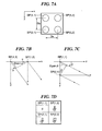
- the audio signal for the speaker unit SP(1,1) is applied with a delay corresponding to a path difference (D x sina (see FIG. 7B )) relative to the speaker unit SP(1, 1).
- the audio signal for the speaker unit SP(2,1) is applied with a delay corresponding to a path difference (D y sinß (see FIG. 7C )) relative to the speaker unit SP(1, 1). Since the speaker unit SP(2,2) has path differences of D y sinß and D x sina relative to the speaker units SP(1,2) and SP(1, 1), an audio signal with a delay corresponding to the sum of the path differences (D x sina + D y sinß) is supplied to the speaker unit SP(2, 2).
- D y sinß see FIG. 7C
- This invention provides a delay time calculation apparatus, a delay time calculation method, and a storage medium storing a program for executing the delay time calculation method, which are able to enable all of speaker units constituting a speaker array to contribute to the formation of a combined wavefront directed to an area specified by a user.
- a delay time calculation apparatus comprising a setting unit adapted to set a target area to which a combined wavefront of acoustic waves output from a plurality of speaker units constituting a speaker array is directed, and a delay time calculation unit adapted to calculate delay times of delayed audio signals to be supplied to respective ones of the speaker units such that ratios at each of which an evaluation object area is occupied by an area to which an acoustic wave output from a corresponding one of the plurality of speaker units reaches earlier than acoustic waves output from other speaker units fall within respective ones of predetermined ranges, the evaluation object area being the target area or being a perspective projection image of the target area onto a predetermined evaluation plane.
- the delay time calculation apparatus of this invention it is possible to enable the speaker units constituting the speaker array to contribute to the formation of a combined wavefront directed to and propagating toward the target area, so that ratios of coverage of the speaker units become predetermined ratios.
- the delay time calculation unit can make an adjustment amount of delay larger for that speaker unit for which a larger deviation of the ratio from the predetermined range is found.
- the delay time calculation unit can make an adjustment amount of delay of the delayed audio signal to be supplied to that speaker unit for which the ratio is deviated from the predetermined range smaller as deviations of the ratios of the speaker units from the predetermined ranges become smaller.
- the delay time calculation unit can determine the ratios at each of which the evaluation object area is occupied by the area to which the acoustic wave output from a corresponding one of the speaker units reaches earlier than acoustic waves output from the other speaker units by identifying which acoustic wave among the acoustic waves output from the speaker units reaches earliest a corresponding one of evaluation points, which are lattice points obtained by dividing the evaluation object area into meshes, or projection points obtained by projecting, onto the target area, lattice points obtained by dividing a perspective projection image of the target area onto the evaluation plane into meshes.
- a spherical plane passing through a gravity of center of the target area and centered on a center of the array plane can be used as the evaluation plane.
- the evaluation points can be distributed according to a sound pressure distribution to be formed in the evaluation object area by sound represented by the combined wavefront.
- the delay time calculation unit can assume one or more virtual speaker units other than the plurality of speaker units, and can calculate delay times of delayed audio signals to be supplied to respective ones of the plurality of speaker units such that the ratios for the plurality of speaker units and the one or more virtual speaker units fall within predetermined ranges.
- a delay time calculation method comprising a setting step of setting a target area to which a combined wavefront of acoustic waves output from a plurality of speaker units constituting a speaker array is directed, and a delay time calculation step of calculating delay times of delayed audio signals to be supplied to respective ones of the speaker units such that ratios at each of which an evaluation object area is occupied by an area to which an acoustic wave output from a corresponding one of the plurality of speaker units reaches earlier than acoustic waves output from other speaker units fall within respective ones of predetermined ranges, the evaluation object area being the target area or being a perspective projection image of the target area onto a predetermined evaluation plane.
- a computer-readable storage medium storing a program for causing a computer to execute the delay time calculation method according to the second aspect of this invention.
- FIG. 1 is a view showing the construction of a speaker array system according to one embodiment of this invention
- FIGS. 2A and 2B are views each showing an example array plane of a speaker array of the speaker array system
- FIG. 3 is a view for explaining an example setting of a target area by a UI providing unit of the speaker array system
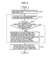
- FIG. 4 is a view showing an example of a delay time calculation process performed by a CPU of a control unit of the speaker array system
- FIG. 5 is a front view of a speaker array for explaining effects achieved by the embodiment
- FIGS. 6A and 6B are views for explaining effects achieved by the embodiment.
- FIGS. 7A to 7D are views for explaining an example of directivity control by a conventional delay array type speaker array system.
- FIG. 1 shows the construction of a speaker array system according to one embodiment of this invention.
- the speaker array system is a so-called delay array type speaker array system.
- the speaker array system 2000 includes a speaker array 2100, a delay unit 2200, an amplification unit 2300, a user interface providing unit (hereinafter referred to as the UI providing unit) 2400, and a control unit 2500.
- UI providing unit user interface providing unit
- the speaker units 2110-i are arranged such that speaker axes extend parallel to one another (i.e., a planer baffle surface is formed).
- a combined wavefront propagating in a certain propagating direction is formed by an envelop of wavefronts of acoustic waves output from the speaker units 2110-i and observed at the same point of time.
- Cone speakers or other speakers having a wide directivity can be used as the speaker units 2110-i.
- the speaker array 2100 can be constructed by speaker units having the same acoustic characteristic or a combination of plural types of speaker units which are different in acoustic characteristic (e.g. , output frequency range). In the case of an arrangement comprised only of speaker units having the same acoustic characteristic as one another, the speaker array 2100 can be formed by speaker units 2111 arranged in a matrix, as shown in FIG. 2A .
- the speaker array 2100 may be formed, for example, by small-sized speaker units 2112 for high-frequency range arranged in a matrix and large-sized speaker units 2113 for low-frequency range arranged to surround the small-sized speaker units 2112, as shown in FIG. 2B . It should be noted that in a case that the speaker array 2100 is constituted by combining plural types of speaker units which are different in coverage of frequency range as shown in FIG. 2B , it is preferable that reproduction frequency bands of the speaker units should at least partly overlap one another.
- the delay unit 2200 is a DSP (digital signal processor), for example.
- the analog signal can be converted into a digital signal by an A/D converter before being supplied to the delay unit 2200.
- so-called one-tap delay processing is implemented as the delay processing.
- the one-tap delay processing can be implemented by use of a shift register or a RAM (random access memory).
- the delay unit 2200 may perform processing to write the input audio signal IN10 into the RAM and read out the input audio signal IN10 from the RAM upon elapse of time periods corresponding to the delays for the speaker units 2110-i, thereby obtaining the delayed audio signals X10-i to be supplied to the amplification unit 2300.
- the delay unit 2200 can be constituted by a smaller scale DSP than in a case that FIR (finite impulse response) type processing is made to generate the delayed audio signals.
- the multipliers 2310-i are supplied with the delayed audio signals X10-i from the delay unit 2200, and multiply the delayed audio signals X10-i by predetermined coefficients supplied from the control unit 2500 to thereby amplify the delayed audio signals X10-i to a level suited to drive the speakers, and then output the amplified audio signals.
- the delayed audio signals X10-i output from the amplification unit 2300 are converted into analog audio signals by D/A converters (not shown in FIG. 1 ) and supplied to respective ones of the speaker units 2110-i.
- window function processing using a rectangular or hanning window may be made on the delayed audio signals X10-i using the multipliers 2310-i.
- the UI providing unit 2400 includes a display device such as a liquid crystal display and an input device such as a mouse, and is used by a user to input various information for use when delay times are computed.
- the information for the delay time computation there may be mentioned array information and area information.
- the array information there may be mentioned a coordinate at which an array plane of the speaker array 2100 is centered, and coordinates at which the speaker units 2110-i of the speaker array 2100 are disposed, in a case that a three dimensional coordinate (having z axis extending in a direction normal to the array plane, y axis extending in a vertical direction, and x axis extending in a horizontal direction (see FIG. 3 )) is defined in a space in which the speaker array 2100 is disposed.
- the array information input via the UI providing unit 2400 is stored as array information 2520b into the nonvolatile memory 2520, as shown in FIG. 1 .
- the area information is information representing a target area to which a combined wavefront of acoustic waves output from respective ones of the speaker units 2110-i propagates (such as for example, information representing a coordinate of the center of gravity of the target area and the shape and size of the target area).
- the target area can be set by the user in various manners. For example, a virtual three dimensional coordinate space shown in FIG. 3 is displayed on the display device, and the user describes a target area within the virtual three dimensional space by use of a mouse or other input device. Alternatively, the user can input numeric values representing a coordinate of the center of gravity of the target area, the shape and size of the target area, etc. to set the target area. In the example shown in FIG.
- the UI providing unit 2400 functions as a setting unit with which the target area is set by the user. As shown in FIG. 1 , the UI providing unit 2400 supplies to the control unit 2500 area information AI10 representing the target area set by the user. In this embodiment, delay times for the delayed audio signals X10-i are evaluated (calculated) based on the target area represented by the area information AI01. Thus, the target area is called "evaluation object area”.
- the control unit 2500 executes a delay time calculation process to calculate the delay times of the delayed audio signals X10-i based on the evaluation object area represented by the area information AI10 and executes a process to supply the calculated delay times to the delay unit 2200.
- the control unit 2500 includes a CPU (central processing unit) 2510, a nonvolatile memory 2520 such as a flash ROM, and a volatile memory 2530 such as a RAM.
- the nonvolatile memory 2520 the array information 2520b is stored and a control program 2520a for causing the CPU 2510 to execute the delay time calculation process is stored in advance, by which the speaker array system 2000 is characterized.
- the volatile memory 2530 is utilized by the CPU 2510 as a work area at execution of the control program 2520a.
- the speaker array system 1 is constructed as described above.
- FIG. 4 shows in flowchart the flow of the delay time calculation process.
- step S100 a variety of values can be used as the initial values of the delay time data D10(i) to be written into the volatile memory 2530.
- the initial values there may be mentioned values that represent delay times for use when a combined wavefront propagating substantially toward the evaluation object area is formed based on acoustic waves output from the speaker units 2110-i by use of the technique disclosed in Japanese Laid-open Patent Publication No. 2006-211230 .
- values representing delay times for use in forming a focus on the center of an evaluation object area, or values representing delay times for use in forming a focus at infinity in a direction from the center of the speaker array 2100 to the center of an evaluation object area can be used as the initial values.
- certain fixed values may also be used as the initial values.
- the delay time data D10(i) subjected to the above described initial setting are optimized by the following processing in steps S110 to S130 and set to the delay unit 2200.
- the earliest-arriving speaker unit distribution indicates a distribution of coverage areas of the speaker units 2110-i in the evaluation object area. Each coverage area indicates an area in the evaluation object area to which an acoustic wave output from the corresponding speaker unit reaches earlier than acoustic waves output from the other speaker units.
- the earliest-arriving speaker unit distribution is calculated as described below.
- D10(i) in formula (1) is delay time data representing a delay time of the delayed audio signal X10-i to be supplied to the corresponding speaker unit 2110-i.
- indicates a distance between the evaluation point Q and the speaker unit 2110-i, which is calculated based on a coordinate of the evaluation point Q and a coordinate of the speaker unit 2110-i represented by the array information 2520b, and c denotes sound velocity.
- the first term on the right side of formula (1) represents a time period required from when the audio signal IN10 from the acoustic source 1000 is input to the speaker array system 2000 until when a sound corresponding to the audio signal is output from the speaker unit 2110-i
- the second term on the right side of formula (1) represents a time period required from when the acoustic wave is output from the speaker unit 2110-i until when the acoustic wave reaches the evaluation point Q.
- the evaluation points are provided in the evaluation object area at equal intervals in the x- and z-axis directions.
- the CPU 2510 determines whether or not there is any speaker unit for which the ratio of the coverage area calculated in step S110 falls outside a predetermined range (step S120).
- the predetermined range can be determined variously.
- a range of plus or minus several percent around a value obtained by dividing the dimensions of the entire evaluation object area (or the total number of the evaluation points in the evaluation object area) by the number of the speaker units 2110-i is used, to thereby make the evaluation object area equally covered by the respective speaker units 2110-i.
- the range of plus or minus several percent can appropriately be determined based on the required accuracy of propagating direction of or the degree of spread of the combined wavefront and the length of time required for the delay time computation.
- step S120 If the answer to step S120 becomes NO (i.e., if the ratios between the coverage areas of all the speaker units and the entire evaluation object area each fall within the predetermined range), the CPU 2501 executes processing in step S140 described later and completes the delay time calculation process. If, on the other hand, the answer to step S120 becomes YES, the CPU 2510 proceeds to step S130.
- step S130 the CPU 2510 determines one or more speaker units whose coverage area ratio is excessively large beyond the predetermined range and one or more speaker units whose coverage area ratio is excessively small beyond the predetermined range. Then, the CPU 2510 increases, by a predetermined adjustment amount ⁇ D, the delay time data stored in the volatile memory 2530 for each speaker unit whose coverage area ratio is excessively large, and decreases, by ⁇ D, the delay time data for each speaker unit whose coverage area ratio is excessively small.
- ⁇ D the delay time data stored in the volatile memory 2530 for each speaker unit whose coverage area ratio is excessively large
- ⁇ D the delay time data for each speaker unit whose coverage area ratio is excessively small.
- the processing is carried out to increase, by ⁇ D, the delay time data D10-k of the delayed audio signal X10-k to be supplied to the speaker unit 2110-k, whereby the required time period T k associated with the speaker unit 2110-k is increased by ⁇ D.
- the speaker unit 2110-k is not necessarily the earliest-arriving speaker unit for the evaluation point Q after the delay time data D10-k is updated.
- the speaker unit 2110-j becomes the earliest-arriving speaker unit for the evaluation point Q, instead of the speaker unit 2110-k.
- the delay time data D10(i) is increased in this manner, the number of evaluation points covered by the speaker unit 2110-i supplied with the delayed audio signal X10-i whose delay time is represented by the delay time data D10(i) (i.e., the ratio of the coverage area to the entire evaluation object area) is decreased and becomes closer to a value falling within the predetermined range.
- the delay time data D10(i) is decreased, the ratio of the coverage area to the entire evaluation object area is increased as apparent from the foregoing description. The above is the reason why the delay time data D10(i) is increased if the ratio of the coverage area to the entire evaluation object area is excessively large, and decreased if the ratio of the coverage area to the entire evaluation object area is excessively small.
- the adjustment amount ⁇ D of the delay time data D10(i) there may be used a fixed value or a value that varies according to an excess (or deficiency) relative to the predetermined range. For example, a value that increases with the increasing deviation from the center of the predetermined range may be used.
- the adjustment amount ⁇ D can be computed according to, e.g., the following formula (2), where
- step S130 After execution of the processing in step S130, the CPU 2510 executes the processing in step S110 again.
- the processing in step S130 is therefore repeatedly carried out until the answer to step S120 becomes NO (i.e., until when the ratios of the coverage areas of all the speaker units 2110-i to the entire evaluation object area fall within the predetermined range).
- a combined wavefront having a predetermined wavefront (in general, an aspherical wavefront) and propagating toward the evaluation object area is formed by acoustic waves output from the speaker units 2110-i.
- Rm 1 to 36
- delay times for the speaker units 2110-9 and 2110-12 are excessively large and there are no coverage areas of these speaker units. In other words, the speaker units 2110-9 and 2110-12 do not contribute to the formation of a wavefront directed to the target area.
- a distribution of coverage areas of the speaker units 2110-m shown in FIG. 6B can be attained. As apparent from a comparison between FIGS.
- all the speaker units contribute to the formation of a combined wavefront propagating toward the evaluation object area.
- the evaluation object area is the target area itself, and therefore all the speaker units contribute to the formation of the combined wavefront propagating toward the target area.
- the directivity of the combined wavefront formed by acoustic waves output from the speaker units 2110-i can intuitively be adjusted based on the position and shape of the target area, and therefore it is unnecessary to calculate, prior to delay time computation, to which directions acoustic waves output from the speaker units 2110-i should be propagated.
- a problem is posed that some speaker units do not contribute to the formation of a combined wavefront propagating the intended direction, even if delay times of delayed audio signals to be supplied to speaker units are adjusted such that acoustic waves output from speaker units 2110-i propagate in predetermined directions.
- the speaker units 2110-i constituting the speaker array 2100 it is possible to enable all the speaker units 2110-i constituting the speaker array 2100 to contribute to the formation of a combined wavefront propagating in the direction intended by the user, by determining delay time data D10(i) of delayed audio signals X10-i to be supplied to the speaker units 2110-i so that coverage areas of the speaker units 2110-i are equalized, as described above.
- the speaker units 2110-i constituting the speaker array 2100 contribute to the formation of a combined wavefront directed to the target area, delay time differences are made small observed when acoustic waves output from the speaker units 2110- i reach the evaluation point. Thus, the resultant wavefront at the evaluation points can be intensified. Since the delay processing executed by the delay unit 2200 of the speaker array system 1 of this embodiment is one-tap delay processing, the delay unit 2200 can be formed by a small scale DSP and therefore the construction of the speaker system 1 can be simplified.
- this invention is applied to a two-dimensional speaker array in which a plurality of speaker units are arranged to form a planar baffle surface.
- this invention is, of course, applicable to a speaker array having speaker units arranged to form a curved baffle surface.
- the coverage areas of the speaker units 2110-i constituting the speaker array 2100 are equalized, but the dimensions of the coverage areas can be made different between speaker units. Specifically, the dimensions of coverage areas can be made different according to types of speaker units or installation positions thereof on the speaker array. The dimensions of coverage areas can be made different according to installation conditions of the speaker units such that coverage areas of speaker units disposed at a larger spacing distance are made larger. In that case, the ratio of the coverage area of each speaker unit to the entire evaluation object area is specified by the user, and it is determined in step S130 whether or not the ratio of coverage area calculated in step S110 for each speaker unit falls with a range around the specified ratio. A width of the range can be specified by the user.
- the delay time data D10(i) can be calculated using other technique. For example, during the process to repeatedly execute the processing in steps S110 to S130 in FIG. 4 , the adjustment amount ⁇ D for delay time may be made smaller for a smaller deviation of the ratio of coverage area from a predetermined range for each speaker unit (for example, the number of speaker units for which the ratio of coverage area falling outside the predetermined range becomes smaller).
- a value of the proportional coefficient a may be made smaller at each execution of the processing in steps S110 to S130 in FIG. 4 . By doing this, it is possible to shorten the processing time required until when the ratio of coverage area of each speaker unit 2110-i converges to within the predetermined range, like a case to rapidly converge an adaptive filter.
- the virtual speaker units dummy speaker units not present actually in the speaker array
- coverage areas may also be assigned to virtual speaker units, and delay times of delayed audio signals to be supplied to the speaker units may be calculated. In that case, only delay times of delayed audio signals supplied to speaker units which are actually present may be made processing objects of the processing to make a minimum delay time zero (processing in step S140 in FIG. 4 ).
- coverage areas can be assigned to respective speaker units in a more orderly fashion.
- the target area itself is the evaluation object area, and lattice points obtained by dividing the evaluation object area into meshes at equal intervals are the evaluation points.
- the evaluation object area may be a perspective projection image of the target area onto a predetermined plane (hereinafter referred to as the evaluation plane), and delay time data D10(i) of delayed audio signals X10-i to be supplied to the speaker units 2110-i may be calculated by executing the processing in FIG. 4 using evaluation points obtained by dividing such an evaluation object area into meshes.
- the evaluation plane there may be mentioned a spherical plane passing through the center of gravity of the target area and centered on the center of the baffle surface of the speaker array 2100, and a plane obtained by slightly tilting in one, two or three of the x, y and z axes a plane containing the target area.
- a spherical plane passing through the center of gravity of the target area and centered on the center of the baffle surface of the speaker array 2100 is used as the evaluation plane and evaluation points are set by dividing the evaluation object area, which is an perspective projection image of the target area onto the evaluation plane, into meshes at equal intervals, distances between the evaluation points on the evaluation object area and the speaker array 2100 are nearly constant irrespective of a relative positional relation between the speaker array 2100 and the target area.
- distances from the speaker array 2100 to the evaluation points vary depending on a relative positional relation between the speaker array 2100 and the evaluation object area (i.e., the directions of evaluation points as seen from the speaker array 2100) in an arrangement where the target area itself is the evaluation object area and evaluation points are set by dividing the evaluation object area into meshes at equal intervals (i.e., the evaluation plane is a plane containing the target area) as described in the embodiment, or in an arrangement where an evaluation plane slightly tilted in one, two, or three axes and evaluation points are set by dividing the evaluation object area, which is a perspective projection image of the target area onto the evaluation plane, into meshes at equal intervals.
- wavefronts having smaller solid angles are assigned to evaluation points located at more distant locations, and therefore the wavefronts are more concentrated to evaluation points located at more distant locations. Since wavefronts are more concentrated to evaluation points at more distant locations, it is expected that sound pressure differences due to distance attenuation are reduced.
- a plane containing the target area and slightly tilted in one, two, or three of the x, y, and z axes is used as the evaluation plane
- the evaluation points are not essentially required to be provided on the evaluation object area.
- the evaluation points may be projection points obtained by projecting, onto the target area, lattice points obtained by dividing the perspective projection image of the target area onto the evaluation plane into meshes at equal intervals. It should be noted that in the setting of evaluation points, it is of course preferable that the evaluation points be set such that a direction pattern is in an appropriate range (e. g. , in front of the speaker array) by taking account of direction patterns of speaker units constituting the speaker array, irrespective whether or not the evaluation points are set on the evaluation object area.
- evaluation points for delay time computation are uniformly provided.
- the ratio of the number of evaluation points is made equivalent to the ratio of dimensions.
- the evaluation point distribution density can, of course, be made different between locations on the evaluation object area. Even in a case that delay times are adjusted such that the ratio of the number of evaluation points covered by each speaker unit is equalized between the speaker units 2110-i, if the evaluation point distribution is not uniform on the evaluation object area, the dimensions of a coverage area per one evaluation point becomes smaller at a location having a higher evaluation point density, resulting in concentrated wavefronts. In an area where the wavefront is concentrated, the sound pressure produced by a combined wavefront formed by the wavefronts becomes high.
- evaluation points are distributed so as to increase the evaluation point density in the particular area.
- the sound pressure, etc. can finely be adjusted according to locations by making the evaluation point distribution on the evaluation object area different between locations.
- the UI providing unit 2400 and the control unit 2500 of the speaker array system 2000 are adapted to function as a setting unit for setting the target area and the control unit 2500 is adapted to function as a delay time calculation unit for calculating delay times of delayed audio signals X10-i to be supplied to the speaker units 2110-i based on the evaluation object area.
- the setting unit and the delay time calculation unit so as to configure a delay time calculation apparatus suitable for delay time control of a delay array type speaker array.
- a control program for causing a computer apparatus to function as the setting unit and the delay time calculation unit may be stored for distribution in a CD-ROM (compact disk-read only memory) or other computer-readable recording medium, or may be able to be downloaded for distribution via the Internet or other electronic communication line.
- the thus distributed control program may be stored into an ordinary computer apparatus and a CPU of the computer apparatus may be operated according to the control program, whereby the ordinary computer apparatus can be used as the delay time calculation apparatus.
Landscapes
- Health & Medical Sciences (AREA)
- General Health & Medical Sciences (AREA)
- Otolaryngology (AREA)
- Physics & Mathematics (AREA)
- Engineering & Computer Science (AREA)
- Acoustics & Sound (AREA)
- Signal Processing (AREA)
- Circuit For Audible Band Transducer (AREA)
- Obtaining Desirable Characteristics In Audible-Bandwidth Transducers (AREA)
Abstract
Description
- The present invention relates to a delay time calculation apparatus for directivity control of a speaker array and relates to a delay time calculation method and a storage medium storing a program therefor.
- As a speaker array system including a speaker array having a plurality of speaker units, there may be mentioned a delay array type speaker array system (see, for example, Japanese Laid-open Patent Publication No.
2006-211230 2006-211230 - In an example technique to specify the propagating direction of a combined wavefront, the propagating direction is specified by vertical and horizontal steering angles. Assuming that a direction normal to an array plane of the speaker array is z axis, a vertical direction is y axis, and a horizontal direction perpendicular to the z and y axes is x axis, the propagating direction of the combined wavefront is specified by rotation angles from the z axis to the x axis and from the z axis to the y axis (horizontal and vertical steering angles). Thus, the propagating direction of the combined wavefront can be represented by a and B degrees by which the combined wavefront is steered leftward in the horizontal direction and downward in the vertical direction, making it easy to intuitively understand the propagation direction.
- In the case of, for example, a speaker array having four speaker units SP(i, j) (i = 1 to 2, j = 1 to 2) arranged in two rows and two columns in the horizontal and vertical directions as shown in
FIG. 7A , if the horizontal and vertical steering angles a and B are specified as shown inFIGS. 7B and 7C , a combined wavefront propagating in the direction represented by the two steering angles a and B can be generated by controlling delay time differences between audio signals supplied to the speaker units SP(i, j), as described below. - For speaker units disposed adjacently in the horizontal direction (e.g., speaker units SP(1,1) and SP(1,2)), audio signals are supplied that have a delay time difference therebetween corresponding to a difference between paths of acoustic waves output from these speaker units. For example, with reference to the audio signal for the speaker unit SP(1,1), the audio signal for the speaker unit SP(1,2) is applied with a delay corresponding to a path difference (Dxsina (see
FIG. 7B )) relative to the speaker unit SP(1, 1). Similarly, for speaker units (e.g., SP(1,1) and SP(2,1)) disposed adjacently in the vertical direction, the audio signal for the speaker unit SP(2,1) is applied with a delay corresponding to a path difference (Dysinß (seeFIG. 7C )) relative to the speaker unit SP(1, 1). Since the speaker unit SP(2,2) has path differences of Dysinß and Dxsina relative to the speaker units SP(1,2) and SP(1, 1), an audio signal with a delay corresponding to the sum of the path differences (Dxsina + Dysinß) is supplied to the speaker unit SP(2, 2). - With the directivity control specifying the propagating direction of a combined wavefront by horizontal and vertical steering angles and applying delays corresponding to path differences shown in
FIGS. 7B and 7C , a problem is sometimes posed that some of the speaker units does not effectively contribute to the formation of the combined wavefront propagating in the direction specified by the steering angles. For example, in a case that relations of Dx = Dy = D and a = β = 45° are satisfied in the speaker array inFIG. 7A , a delay for the speaker unit SP(2,2) becomes excessively large as compared to those for the speaker units SP(1,2) and SP(2,1) (seeFIG. 7D ), which causes the just-mentioned problem. - This invention provides a delay time calculation apparatus, a delay time calculation method, and a storage medium storing a program for executing the delay time calculation method, which are able to enable all of speaker units constituting a speaker array to contribute to the formation of a combined wavefront directed to an area specified by a user.
- According to a first aspect of this invention, there is provided a delay time calculation apparatus comprising a setting unit adapted to set a target area to which a combined wavefront of acoustic waves output from a plurality of speaker units constituting a speaker array is directed, and a delay time calculation unit adapted to calculate delay times of delayed audio signals to be supplied to respective ones of the speaker units such that ratios at each of which an evaluation object area is occupied by an area to which an acoustic wave output from a corresponding one of the plurality of speaker units reaches earlier than acoustic waves output from other speaker units fall within respective ones of predetermined ranges, the evaluation object area being the target area or being a perspective projection image of the target area onto a predetermined evaluation plane.
- With the delay time calculation apparatus of this invention, it is possible to enable the speaker units constituting the speaker array to contribute to the formation of a combined wavefront directed to and propagating toward the target area, so that ratios of coverage of the speaker units become predetermined ratios.
- The delay time calculation unit can make an adjustment amount of delay larger for that speaker unit for which a larger deviation of the ratio from the predetermined range is found.
- In this case, it is possible to rapidly converge the ratio of coverage of each speaker unit to a value falling within the predetermined range.
- The delay time calculation unit can make an adjustment amount of delay of the delayed audio signal to be supplied to that speaker unit for which the ratio is deviated from the predetermined range smaller as deviations of the ratios of the speaker units from the predetermined ranges become smaller.
- In this case, it is possible to rapidly converge the ratio of coverage of each speaker unit to a value falling within the predetermined range.
- The delay time calculation unit can determine the ratios at each of which the evaluation object area is occupied by the area to which the acoustic wave output from a corresponding one of the speaker units reaches earlier than acoustic waves output from the other speaker units by identifying which acoustic wave among the acoustic waves output from the speaker units reaches earliest a corresponding one of evaluation points, which are lattice points obtained by dividing the evaluation object area into meshes, or projection points obtained by projecting, onto the target area, lattice points obtained by dividing a perspective projection image of the target area onto the evaluation plane into meshes.
- A spherical plane passing through a gravity of center of the target area and centered on a center of the array plane can be used as the evaluation plane.
- The evaluation points can be distributed according to a sound pressure distribution to be formed in the evaluation object area by sound represented by the combined wavefront.
- The delay time calculation unit can assume one or more virtual speaker units other than the plurality of speaker units, and can calculate delay times of delayed audio signals to be supplied to respective ones of the plurality of speaker units such that the ratios for the plurality of speaker units and the one or more virtual speaker units fall within predetermined ranges.
- According to a second aspect of this invention, there is provided a delay time calculation method comprising a setting step of setting a target area to which a combined wavefront of acoustic waves output from a plurality of speaker units constituting a speaker array is directed, and a delay time calculation step of calculating delay times of delayed audio signals to be supplied to respective ones of the speaker units such that ratios at each of which an evaluation object area is occupied by an area to which an acoustic wave output from a corresponding one of the plurality of speaker units reaches earlier than acoustic waves output from other speaker units fall within respective ones of predetermined ranges, the evaluation object area being the target area or being a perspective projection image of the target area onto a predetermined evaluation plane.
- According to a third aspect of this invention, there is provided a computer-readable storage medium storing a program for causing a computer to execute the delay time calculation method according to the second aspect of this invention.
- Further features of the present invention will become apparent from the following description of an exemplary embodiment with reference to the attached drawings.
-
FIG. 1 is a view showing the construction of a speaker array system according to one embodiment of this invention; -
FIGS. 2A and 2B are views each showing an example array plane of a speaker array of the speaker array system; -
FIG. 3 is a view for explaining an example setting of a target area by a UI providing unit of the speaker array system; -
FIG. 4 is a view showing an example of a delay time calculation process performed by a CPU of a control unit of the speaker array system; -
FIG. 5 is a front view of a speaker array for explaining effects achieved by the embodiment; -
FIGS. 6A and 6B are views for explaining effects achieved by the embodiment; and -
FIGS. 7A to 7D are views for explaining an example of directivity control by a conventional delay array type speaker array system. - The present invention will now be described in detail below with reference to the drawings showing a preferred embodiment thereof.
-
FIG. 1 shows the construction of a speaker array system according to one embodiment of this invention. The speaker array system is a so-called delay array type speaker array system. As shown inFIG. 1 , thespeaker array system 2000 includes aspeaker array 2100, adelay unit 2200, anamplification unit 2300, a user interface providing unit (hereinafter referred to as the UI providing unit) 2400, and acontrol unit 2500. - The
speaker array 2100 includes speaker units 2110-i (i = 1 to N, where N represents a natural number not less than 2). The speaker units 2110-i are arranged such that speaker axes extend parallel to one another (i.e., a planer baffle surface is formed). In thespeaker array system 2000 inFIG. 1 , a combined wavefront propagating in a certain propagating direction is formed by an envelop of wavefronts of acoustic waves output from the speaker units 2110-i and observed at the same point of time. Cone speakers or other speakers having a wide directivity can be used as the speaker units 2110-i. Thespeaker array 2100 can be constructed by speaker units having the same acoustic characteristic or a combination of plural types of speaker units which are different in acoustic characteristic (e.g. , output frequency range). In the case of an arrangement comprised only of speaker units having the same acoustic characteristic as one another, thespeaker array 2100 can be formed by speaker units 2111 arranged in a matrix, as shown inFIG. 2A . On the other hand, in the case of an arrangement comprised of a combination of plural types of speaker units having different acoustic characteristics, thespeaker array 2100 may be formed, for example, by small-sized speaker units 2112 for high-frequency range arranged in a matrix and large-sized speaker units 2113 for low-frequency range arranged to surround the small-sized speaker units 2112, as shown inFIG. 2B . It should be noted that in a case that thespeaker array 2100 is constituted by combining plural types of speaker units which are different in coverage of frequency range as shown inFIG. 2B , it is preferable that reproduction frequency bands of the speaker units should at least partly overlap one another. - The
delay unit 2200 is a DSP (digital signal processor), for example. Thedelay unit 2200 performs delay processing on an input audio signal IN10 supplied from anacoustic source 1000 to generate delayed audio signals X10-i. (i = 1 to N). In a case that an analog signal is input from theacoustic source 1000 as the input audio signal IN10, the analog signal can be converted into a digital signal by an A/D converter before being supplied to thedelay unit 2200. In this embodiment, so-called one-tap delay processing is implemented as the delay processing. The one-tap delay processing can be implemented by use of a shift register or a RAM (random access memory). For example, in the case of using a RAM, thedelay unit 2200 may perform processing to write the input audio signal IN10 into the RAM and read out the input audio signal IN10 from the RAM upon elapse of time periods corresponding to the delays for the speaker units 2110-i, thereby obtaining the delayed audio signals X10-i to be supplied to theamplification unit 2300. With this embodiment that generates the delayed audio signals X10-i by the one-tap delay processing, thedelay unit 2200 can be constituted by a smaller scale DSP than in a case that FIR (finite impulse response) type processing is made to generate the delayed audio signals. - As shown in
FIG. 1 , theamplification unit 2300 includes multipliers 2310-i (i = 1 to N) corresponding to respective ones of the speaker units 2110-i. The multipliers 2310-i are supplied with the delayed audio signals X10-i from thedelay unit 2200, and multiply the delayed audio signals X10-i by predetermined coefficients supplied from thecontrol unit 2500 to thereby amplify the delayed audio signals X10-i to a level suited to drive the speakers, and then output the amplified audio signals. The delayed audio signals X10-i output from theamplification unit 2300 are converted into analog audio signals by D/A converters (not shown inFIG. 1 ) and supplied to respective ones of the speaker units 2110-i. In a case that shading processing is performed to suppress sidelobe, window function processing using a rectangular or hanning window may be made on the delayed audio signals X10-i using the multipliers 2310-i. - The
UI providing unit 2400 includes a display device such as a liquid crystal display and an input device such as a mouse, and is used by a user to input various information for use when delay times are computed. As the information for the delay time computation, there may be mentioned array information and area information. As an example of the array information, there may be mentioned a coordinate at which an array plane of thespeaker array 2100 is centered, and coordinates at which the speaker units 2110-i of thespeaker array 2100 are disposed, in a case that a three dimensional coordinate (having z axis extending in a direction normal to the array plane, y axis extending in a vertical direction, and x axis extending in a horizontal direction (seeFIG. 3 )) is defined in a space in which thespeaker array 2100 is disposed. The array information input via theUI providing unit 2400 is stored asarray information 2520b into thenonvolatile memory 2520, as shown inFIG. 1 . - On the other hand, the area information is information representing a target area to which a combined wavefront of acoustic waves output from respective ones of the speaker units 2110-i propagates (such as for example, information representing a coordinate of the center of gravity of the target area and the shape and size of the target area). The target area can be set by the user in various manners. For example, a virtual three dimensional coordinate space shown in
FIG. 3 is displayed on the display device, and the user describes a target area within the virtual three dimensional space by use of a mouse or other input device. Alternatively, the user can input numeric values representing a coordinate of the center of gravity of the target area, the shape and size of the target area, etc. to set the target area. In the example shown inFIG. 3 , a rectangular target area is set. However, the target area has any shape as long as it defines a closed region of a certain shape. Thus, theUI providing unit 2400 functions as a setting unit with which the target area is set by the user. As shown inFIG. 1 , theUI providing unit 2400 supplies to thecontrol unit 2500 area information AI10 representing the target area set by the user. In this embodiment, delay times for the delayed audio signals X10-i are evaluated (calculated) based on the target area represented by the area information AI01. Thus, the target area is called "evaluation object area". - The
control unit 2500 executes a delay time calculation process to calculate the delay times of the delayed audio signals X10-i based on the evaluation object area represented by the area information AI10 and executes a process to supply the calculated delay times to thedelay unit 2200. As shown inFIG. 1 , thecontrol unit 2500 includes a CPU (central processing unit) 2510, anonvolatile memory 2520 such as a flash ROM, and avolatile memory 2530 such as a RAM. In thenonvolatile memory 2520, thearray information 2520b is stored and acontrol program 2520a for causing theCPU 2510 to execute the delay time calculation process is stored in advance, by which thespeaker array system 2000 is characterized. On the other hand, thevolatile memory 2530 is utilized by theCPU 2510 as a work area at execution of thecontrol program 2520a. The speaker array system 1 is constructed as described above. - Next, a description is given of the delay time calculation process executed by the
CPU 2510 of thecontrol unit 2500 in accordance with thecontrol program 2520a. -
FIG. 4 shows in flowchart the flow of the delay time calculation process. As shown inFIG. 4 , theCPU 2510 first writes into thevolatile memory 2530 initial values of delay time data D10(i) (i = 1 to N) representing delay times of the delayed audio signals X10-i to be supplied to respective ones of the speaker units 2110-i (step S100). In step S100, a variety of values can be used as the initial values of the delay time data D10(i) to be written into thevolatile memory 2530. For example, as the initial values, there may be mentioned values that represent delay times for use when a combined wavefront propagating substantially toward the evaluation object area is formed based on acoustic waves output from the speaker units 2110-i by use of the technique disclosed in Japanese Laid-open Patent Publication No.2006-211230 speaker array 2100 to the center of an evaluation object area can be used as the initial values. Of course, certain fixed values may also be used as the initial values. In the delay time calculation process of this embodiment, the delay time data D10(i) subjected to the above described initial setting are optimized by the following processing in steps S110 to S130 and set to thedelay unit 2200. - In step S110, the
CPU 2510 calculates an earliest-arriving speaker unit distribution for a case
where the delay time data D10(i) (i = 1 to N) stored in thevolatile memory 2530 are set to thedelay unit 2200. The earliest-arriving speaker unit distribution indicates a distribution of coverage areas of the speaker units 2110-i in the evaluation object area. Each coverage area indicates an area in the evaluation object area to which an acoustic wave output from the corresponding speaker unit reaches earlier than acoustic waves output from the other speaker units. The earliest-arriving speaker unit distribution is calculated as described below. - The
CPU 2510 divides the evaluation object area into meshes at equal intervals in the x- and z-axis directions. As shown inFIG. 3 , evaluation points Q are at lattice points, i.e., at intersections of the meshes. Next, the CPU identifies which acoustic wave among acoustic waves output from the speaker units 2110-i (i = 1 to N) reaches earliest each evaluation point. In the following, the speaker unit that outputs the acoustic wave which reaches earliest a given evaluation point is called the earliest-arriving speaker unit for the evaluation point. The earliest-arriving speaker unit for a certain evaluation point Q on the evaluation object area can be identified, for example, by calculating values Ti (i = 1 to N) in accordance with the following formula (1) for the respective speaker units 2110-i and identifying an index i that corresponds to the minimum value among the values Ti which are N in number. It should be noted that D10(i) in formula (1) is delay time data representing a delay time of the delayed audio signal X10-i to be supplied to the corresponding speaker unit 2110-i. In formula (1), |Q-SP(i)| indicates a distance between the evaluation point Q and the speaker unit 2110-i, which is calculated based on a coordinate of the evaluation point Q and a coordinate of the speaker unit 2110-i represented by thearray information 2520b, and c denotes sound velocity. Thus, the first term on the right side of formula (1) represents a time period required from when the audio signal IN10 from theacoustic source 1000 is input to thespeaker array system 2000 until when a sound corresponding to the audio signal is output from the speaker unit 2110-i, and the second term on the right side of formula (1) represents a time period required from when the acoustic wave is output from the speaker unit 2110-i until when the acoustic wave reaches the evaluation point Q. - Ti = D10(i) + |Q-SP(i)|/c ... (1)
- Upon completion of the identification of the earliest-arriving speaker units for all the evaluation points in the evaluation object area, the
CPU 2510 adds up, in respect of each of the speaker unit 2110-i (i = 1 to N), the number of evaluation points for which a given speaker unit is the earliest-arriving speaker unit. As previously described, in this embodiment, the evaluation points are provided in the evaluation object area at equal intervals in the x- and z-axis directions. Thus, a value obtained by dividing the number of evaluation points for which a given speaker unit is the earliest-arriving speaker unit by the total number of the evaluation points in the evaluation object area nearly coincides with a ratio of the dimensions of coverage area of the speaker unit to that of the entire evaluation object area. In this manner, ratios of coverage areas of the speaker units 2110-i (i = 1 to N) to the entire evaluation object area are calculated. - Next, the
CPU 2510 determines whether or not there is any speaker unit for which the ratio of the coverage area calculated in step S110 falls outside a predetermined range (step S120). The predetermined range can be determined variously. In this embodiment, as the predetermined range, a range of plus or minus several percent around a value obtained by dividing the dimensions of the entire evaluation object area (or the total number of the evaluation points in the evaluation object area) by the number of the speaker units 2110-i is used, to thereby make the evaluation object area equally covered by the respective speaker units 2110-i. It should be noted that the range of plus or minus several percent can appropriately be determined based on the required accuracy of propagating direction of or the degree of spread of the combined wavefront and the length of time required for the delay time computation. If the answer to step S120 becomes NO (i.e., if the ratios between the coverage areas of all the speaker units and the entire evaluation object area each fall within the predetermined range), the CPU 2501 executes processing in step S140 described later and completes the delay time calculation process. If, on the other hand, the answer to step S120 becomes YES, theCPU 2510 proceeds to step S130. - In step S130, the
CPU 2510 determines one or more speaker units whose coverage area ratio is excessively large beyond the predetermined range and one or more speaker units whose coverage area ratio is excessively small beyond the predetermined range. Then, theCPU 2510 increases, by a predetermined adjustment amount ΔD, the delay time data stored in thevolatile memory 2530 for each speaker unit whose coverage area ratio is excessively large, and decreases, by ΔD, the delay time data for each speaker unit whose coverage area ratio is excessively small. In the following, a description is given of the reason why the delay time data is increased if the ratio of the coverage area to the entire evaluation object area is excessively large and decreased if the ratio is excessively small. - The time period Ti required from when the audio signal IN10 is input to the
speaker system 2000 until when the acoustic wave output from the speaker unit 2110-i (i = 1 to N) reaches a given evaluation point Q is represented by formula (1), as previously described. In a case that the earliest-arriving speaker unit for the evaluation point Q is the k-th speaker unit 2110-k and the ratio of the coverage area of the speaker unit 2110-k to the entire evaluation object area is excessively large, the processing is carried out to increase, by ΔD, the delay time data D10-k of the delayed audio signal X10-k to be supplied to the speaker unit 2110-k, whereby the required time period Tk associated with the speaker unit 2110-k is increased by ΔD. - If the delay time data D10-k is updated as described above, a change occurs in the time period required for the acoustic wave output from the speaker unit 2110-k to reach the evaluation point Q. Thus, the speaker unit 2110-k is not necessarily the earliest-arriving speaker unit for the evaluation point Q after the delay time data D10-k is updated. In a case, for example, that the j-th speaker unit 2110-j (j ≠ k) is the smallest next to the speaker unit 2110-k in the required time period in formula (1) and the required time period Tj satisfies a relation of Tk < Tj < Tk + ΔD, the speaker unit 2110-j becomes the earliest-arriving speaker unit for the evaluation point Q, instead of the speaker unit 2110-k. If the delay time data D10(i) is increased in this manner, the number of evaluation points covered by the speaker unit 2110-i supplied with the delayed audio signal X10-i whose delay time is represented by the delay time data D10(i) (i.e., the ratio of the coverage area to the entire evaluation object area) is decreased and becomes closer to a value falling within the predetermined range. On the other hand, if the delay time data D10(i) is decreased, the ratio of the coverage area to the entire evaluation object area is increased as apparent from the foregoing description. The above is the reason why the delay time data D10(i) is increased if the ratio of the coverage area to the entire evaluation object area is excessively large, and decreased if the ratio of the coverage area to the entire evaluation object area is excessively small.
- As the adjustment amount ΔD of the delay time data D10(i), there may be used a fixed value or a value that varies according to an excess (or deficiency) relative to the predetermined range. For example, a value that increases with the increasing deviation from the center of the predetermined range may be used. The adjustment amount ΔD can be computed according to, e.g., the following formula (2), where |R| represents the magnitude of the excess (or deficiency) and a represents a predetermined proportional constant.
- ΔD = a × |R| ... (2)
- After execution of the processing in step S130, the
CPU 2510 executes the processing in step S110 again. The processing in step S130 is therefore repeatedly carried out until the answer to step S120 becomes NO (i.e., until when the ratios of the coverage areas of all the speaker units 2110-i to the entire evaluation object area fall within the predetermined range). - If the answer to step S120 becomes NO, the
CPU 2510 carries out processing to update each of the delay time data D10(i) (i = 1 to N) stored in thevolatile memory 2530 to a value obtained by subtracting the smallest one among the delay time data from each thereof and set the updated data to the delay unit 2200 (step S140), and completes the delay time calculation process. The reason why the value obtained by subtracting the smallest one among the delay time data D10(i) from each thereof is set to thedelay unit 2200 as the delay time of the delayed audio signal X10-i supplied to the speaker unit 2110-i is to reduce the entire delay time and prevent the delay time from having a negative value. - After completion of the above described setting of the delay times for the speaker units 2110-i (i = 1 to N), the
delay unit 2200 performs processing to apply delays corresponding to the delay times to the input audio signal IN10 supplied from theacoustic source 1000, to thereby generate and output the delayed audio signals X10-i (i = 1 to N). Sounds corresponding to the delayed audio signals X10-i are output from the speaker units 2110-i. A combined wavefront having a predetermined wavefront (in general, an aspherical wavefront) and propagating toward the evaluation object area is formed by acoustic waves output from the speaker units 2110-i. - In a conventional delay array type control, for a
speaker array 2100 having 36 speaker units 2110-1 to 2110-36 arranged as shown inFIG. 5 , for example, delay times of delayed audio signals to be supplied to speaker units are calculated as follows: Specifically, as shown inFIG. 6A , an array plane is projected onto a target area (shown by a dotted line) such as to cover the target area, and based on the projected image, target arrival points SP1 to SP36 of acoustic waves output from the speaker units 2110-m (m = 1 to 36) are determined. Then, in accordance with differences between paths connecting the speaker units 2110-m and the target arrival points SPm, delay times of delayed audio signals to be supplied to the speaker units 2110-m are calculated. InFIG. 6A , coverage areas of the speaker units 2110-m are denoted by Rm (m = 1 to 36) for a case where the delay times are determined as described above. As apparent fromFIG. 6A , delay times for the speaker units 2110-9 and 2110-12 are excessively large and there are no coverage areas of these speaker units. In other words, the speaker units 2110-9 and 2110-12 do not contribute to the formation of a wavefront directed to the target area. On the other hand, in a case that delayed audio signals with delay times calculated according to the technique of this embodiment are supplied to the speaker units, a distribution of coverage areas of the speaker units 2110-m shown inFIG. 6B can be attained. As apparent from a comparison betweenFIGS. 6B and 6A , according to this embodiment, all the speaker units contribute to the formation of a combined wavefront propagating toward the evaluation object area. In this embodiment, the evaluation object area is the target area itself, and therefore all the speaker units contribute to the formation of the combined wavefront propagating toward the target area. - As described above, according to this embodiment, the directivity of the combined wavefront formed by acoustic waves output from the speaker units 2110-i can intuitively be adjusted based on the position and shape of the target area, and therefore it is unnecessary to calculate, prior to delay time computation, to which directions acoustic waves output from the speaker units 2110-i should be propagated. Conventionally, a problem is posed that some speaker units do not contribute to the formation of a combined wavefront propagating the intended direction, even if delay times of delayed audio signals to be supplied to speaker units are adjusted such that acoustic waves output from speaker units 2110-i propagate in predetermined directions. On the other hand, according to this embodiment, it is possible to enable all the speaker units 2110-i constituting the
speaker array 2100 to contribute to the formation of a combined wavefront propagating in the direction intended by the user, by determining delay time data D10(i) of delayed audio signals X10-i to be supplied to the speaker units 2110-i so that coverage areas of the speaker units 2110-i are equalized, as described above. According to this embodiment, since the speaker units 2110-i constituting thespeaker array 2100 contribute to the formation of a combined wavefront directed to the target area, delay time differences are made small observed when acoustic waves output from the speaker units 2110- i reach the evaluation point. Thus, the resultant wavefront at the evaluation points can be intensified. Since the delay processing executed by thedelay unit 2200 of the speaker array system 1 of this embodiment is one-tap delay processing, thedelay unit 2200 can be formed by a small scale DSP and therefore the construction of the speaker system 1 can be simplified. - In the above, there has been described one embodiment of this invention, which may be modified variously as described below.
- In the embodiment, this invention is applied to a two-dimensional speaker array in which a plurality of speaker units are arranged to form a planar baffle surface. However, this invention is, of course, applicable to a speaker array having speaker units arranged to form a curved baffle surface.
- In the embodiment, the coverage areas of the speaker units 2110-i constituting the
speaker array 2100 are equalized, but the dimensions of the coverage areas can be made different between speaker units. Specifically, the dimensions of coverage areas can be made different according to types of speaker units or installation positions thereof on the speaker array. The dimensions of coverage areas can be made different according to installation conditions of the speaker units such that coverage areas of speaker units disposed at a larger spacing distance are made larger. In that case, the ratio of the coverage area of each speaker unit to the entire evaluation object area is specified by the user, and it is determined in step S130 whether or not the ratio of coverage area calculated in step S110 for each speaker unit falls with a range around the specified ratio. A width of the range can be specified by the user. In a case that a narrow width of the range is specified, it is possible for the ratio of coverage area of the corresponding speaker unit to the entire evaluation object area to converge to a value close to the specified ratio, but a computation time required for the convergence becomes long. On the other hand, if a wide width of the range is specified, the computation time can be shortened, but a deviation of the ratio of the coverage area of each speaker unit to the entire evaluation object area from the specified ratio becomes large. - In the embodiment, there have been described cases where a fixed value and a value (see, formula (2)) determined according to the excess (or deficiency) R of the ratio of the coverage area of each speaker unit 2110-i to the entire evaluation object area are respectively used as adjustment amount ΔD for adjustment of delay time data D10(i). However, the delay time data D10(i) can be calculated using other technique. For example, during the process to repeatedly execute the processing in steps S110 to S130 in
FIG. 4 , the adjustment amount ΔD for delay time may be made smaller for a smaller deviation of the ratio of coverage area from a predetermined range for each speaker unit (for example, the number of speaker units for which the ratio of coverage area falling outside the predetermined range becomes smaller). In a case, for example, that a value computed according to formula (2) is used as the adjustment amount ΔD, a value of the proportional coefficient a may be made smaller at each execution of the processing in steps S110 to S130 inFIG. 4 . By doing this, it is possible to shorten the processing time required until when the ratio of coverage area of each speaker unit 2110-i converges to within the predetermined range, like a case to rapidly converge an adaptive filter. - In the embodiment, the ratios of coverage area of a plurality of speaker units 2110-i (i=1 to N) constituting the
speaker array 2100 to the entire evaluation object area are calculated, and delay times of delayed audio signals X10-i to be supplied to the speaker units 2110-i are determined. Alternatively, dummy speaker units not present actually in the speaker array (hereinafter referred to as the virtual speaker units) may be assumed, coverage areas may also be assigned to virtual speaker units, and delay times of delayed audio signals to be supplied to the speaker units may be calculated. In that case, only delay times of delayed audio signals supplied to speaker units which are actually present may be made processing objects of the processing to make a minimum delay time zero (processing in step S140 inFIG. 4 ). By executing the delay time calculation using such virtual speaker units, coverage areas can be assigned to respective speaker units in a more orderly fashion. - In the embodiment, the target area itself is the evaluation object area, and lattice points obtained by dividing the evaluation object area into meshes at equal intervals are the evaluation points. Alternatively, the evaluation object area may be a perspective projection image of the target area onto a predetermined plane (hereinafter referred to as the evaluation plane), and delay time data D10(i) of delayed audio signals X10-i to be supplied to the speaker units 2110-i may be calculated by executing the processing in
FIG. 4 using evaluation points obtained by dividing such an evaluation object area into meshes. As examples of the evaluation plane, there may be mentioned a spherical plane passing through the center of gravity of the target area and centered on the center of the baffle surface of thespeaker array 2100, and a plane obtained by slightly tilting in one, two or three of the x, y and z axes a plane containing the target area. - In a case, for example, that a spherical plane passing through the center of gravity of the target area and centered on the center of the baffle surface of the
speaker array 2100 is used as the evaluation plane and evaluation points are set by dividing the evaluation object area, which is an perspective projection image of the target area onto the evaluation plane, into meshes at equal intervals, distances between the evaluation points on the evaluation object area and thespeaker array 2100 are nearly constant irrespective of a relative positional relation between thespeaker array 2100 and the target area. Thus, if the coverage areas of the speaker units 2110-i (i = 1 to N) are equalized, solid angles corresponding to these coverage areas become constant, making it possible to prevent a wavefront from being unbalanced due to difference in distance to the evaluation points. On the other hand, distances from thespeaker array 2100 to the evaluation points vary depending on a relative positional relation between thespeaker array 2100 and the evaluation object area (i.e., the directions of evaluation points as seen from the speaker array 2100) in an arrangement where the target area itself is the evaluation object area and evaluation points are set by dividing the evaluation object area into meshes at equal intervals (i.e., the evaluation plane is a plane containing the target area) as described in the embodiment, or in an arrangement where an evaluation plane slightly tilted in one, two, or three axes and evaluation points are set by dividing the evaluation object area, which is a perspective projection image of the target area onto the evaluation plane, into meshes at equal intervals. When coverage areas are equalized on an evaluation plane with which distances to evaluation points vary according to direction, wavefronts having smaller solid angles are assigned to evaluation points located at more distant locations, and therefore the wavefronts are more concentrated to evaluation points located at more distant locations. Since wavefronts are more concentrated to evaluation points at more distant locations, it is expected that sound pressure differences due to distance attenuation are reduced. In the arrangement where a plane containing the target area and slightly tilted in one, two, or three of the x, y, and z axes is used as the evaluation plane, it is especially effective to use, as the evaluation plane, a plane obtained by rotation (an amount of rotation can be specified by the user) around a rotary axis passing through the center of the target area and extending perpendicular to a plane (auxiliary plane) that extends perpendicular to the target area and contains the center of the baffle surface of thespeaker array 2100 and the center of the target area. - The evaluation points are not essentially required to be provided on the evaluation object area. Alternatively, the evaluation points may be projection points obtained by projecting, onto the target area, lattice points obtained by dividing the perspective projection image of the target area onto the evaluation plane into meshes at equal intervals. It should be noted that in the setting of evaluation points, it is of course preferable that the evaluation points be set such that a direction pattern is in an appropriate range (e. g. , in front of the speaker array) by taking account of direction patterns of speaker units constituting the speaker array, irrespective whether or not the evaluation points are set on the evaluation object area.
- In the embodiment, evaluation points for delay time computation are uniformly provided. In that case, the ratio of the number of evaluation points is made equivalent to the ratio of dimensions. However, the evaluation point distribution density can, of course, be made different between locations on the evaluation object area. Even in a case that delay times are adjusted such that the ratio of the number of evaluation points covered by each speaker unit is equalized between the speaker units 2110-i, if the evaluation point distribution is not uniform on the evaluation object area, the dimensions of a coverage area per one evaluation point becomes smaller at a location having a higher evaluation point density, resulting in concentrated wavefronts. In an area where the wavefront is concentrated, the sound pressure produced by a combined wavefront formed by the wavefronts becomes high. Utilizing this, in order to, e.g., increase the sound pressure in a particular area in the evaluation object area, evaluation points are distributed so as to increase the evaluation point density in the particular area. In this manner, the sound pressure, etc. can finely be adjusted according to locations by making the evaluation point distribution on the evaluation object area different between locations.
- In the embodiment, the
UI providing unit 2400 and thecontrol unit 2500 of thespeaker array system 2000 are adapted to function as a setting unit for setting the target area and thecontrol unit 2500 is adapted to function as a delay time calculation unit for calculating delay times of delayed audio signals X10-i to be supplied to the speaker units 2110-i based on the evaluation object area. However, it is, of course, possible to combine the setting unit and the delay time calculation unit so as to configure a delay time calculation apparatus suitable for delay time control of a delay array type speaker array. A control program for causing a computer apparatus to function as the setting unit and the delay time calculation unit (in the embodiment, the control program 2502a) may be stored for distribution in a CD-ROM (compact disk-read only memory) or other computer-readable recording medium, or may be able to be downloaded for distribution via the Internet or other electronic communication line. The thus distributed control program may be stored into an ordinary computer apparatus and a CPU of the computer apparatus may be operated according to the control program, whereby the ordinary computer apparatus can be used as the delay time calculation apparatus.
Claims (9)
- A delay time calculation apparatus comprising:a setting unit adapted to set a target area to which a combined wavefront of acoustic waves output from a plurality of speaker units constituting a speaker array is directed; anda delay time calculation unit adapted to calculate delay times of delayed audio signals to be supplied to respective ones of the speaker units such that ratios at each of which an evaluation object area is occupied by an area to which an acoustic wave output from a corresponding one of the plurality of speaker units reaches earlier than acoustic waves output from other speaker units fall within respective ones of predetermined ranges, the evaluation object area being the target area or being a perspective projection image of the target area onto a predetermined evaluation plane.
- The delay time calculation apparatus according to claim 1, wherein the delay time calculation unit makes an adjustment amount of delay larger for that speaker unit for which a larger deviation of the ratio from the predetermined range is found.
- The delay time calculation apparatus according to claim 1, wherein the delay time calculation unit makes an adjustment amount of delay of the delayed audio signal to be supplied to that speaker unit for which the ratio is deviated from the predetermined range smaller as deviations of the ratios of the speaker units from the predetermined ranges become smaller.
- The delay time calculation apparatus according to claim 1, wherein the delay time calculation unit determines the ratios at each of which the evaluation object area is occupied by the area to which the acoustic wave output from a corresponding one of the speaker units reaches earlier than acoustic waves output from the other speaker units by identifying which acoustic wave among the acoustic waves output from the speaker units reaches earliest a corresponding one of evaluation points, which are lattice points obtained by dividing the evaluation object area into meshes, or projection points obtained by projecting, onto the target area, lattice points obtained by dividing a perspective projection image of the target area onto the evaluation plane into meshes.
- The delay time calculation apparatus according to claim 4, wherein a spherical plane passing through a gravity of center of the target area and centered on a center of the array plane is used as the evaluation plane.
- The delay time calculation apparatus according to claim 4, wherein the evaluation points are distributed according to a sound pressure distribution to be formed in the evaluation object area by sound represented by the combined wavefront.
- The delay time calculation apparatus according to claim 1, wherein the delay time calculation unit assumes one or more virtual speaker units other than the plurality of speaker units, and calculates delay times of delayed audio signals to be supplied to respective ones of the plurality of speaker units such that the ratios for the plurality of speaker units and the one or more virtual speaker units fall within predetermined ranges.
- A delay time calculation method comprising:a setting step of setting a target area to which a combined wavefront of acoustic waves output from a plurality of speaker units constituting a speaker array is directed; anda delay time calculation step of calculating delay times of delayed audio signals to be supplied to respective ones of the speaker units such that ratios at each of which an evaluation object area is occupied by an area to which an acoustic wave output from a corresponding one of the plurality of speaker units reaches earlier than acoustic waves output from other speaker units fall within respective ones of predetermined ranges, the evaluation object area being the target area or being a perspective projection image of the target area onto a predetermined evaluation plane.
- A computer-readable storage medium storing a program for causing a computer to execute the delay time calculation method as set forth in claim 8.
Applications Claiming Priority (1)
| Application Number | Priority Date | Filing Date | Title |
|---|---|---|---|
| JP2008133167A JP5195018B2 (en) | 2008-05-21 | 2008-05-21 | Delay amount calculation apparatus and program |
Publications (2)
| Publication Number | Publication Date |
|---|---|
| EP2124478A1 true EP2124478A1 (en) | 2009-11-25 |
| EP2124478B1 EP2124478B1 (en) | 2016-05-18 |
Family
ID=40802153
Family Applications (1)
| Application Number | Title | Priority Date | Filing Date |
|---|---|---|---|
| EP09006619.2A Not-in-force EP2124478B1 (en) | 2008-05-21 | 2009-05-15 | Delay time calculation apparatus, delay time calculation method, and storage medium storing program therefor |
Country Status (3)
| Country | Link |
|---|---|
| US (1) | US8275160B2 (en) |
| EP (1) | EP2124478B1 (en) |
| JP (1) | JP5195018B2 (en) |
Families Citing this family (4)
| Publication number | Priority date | Publication date | Assignee | Title |
|---|---|---|---|---|
| TWI470937B (en) * | 2009-09-04 | 2015-01-21 | Mstar Semiconductor Inc | Frequency calibration apparatus and method of phase locked loop |
| JP5852325B2 (en) * | 2011-05-10 | 2016-02-03 | 日本放送協会 | Sound image localization improvement device |
| US9911406B2 (en) * | 2013-03-15 | 2018-03-06 | Loud Audio, Llc | Method and system for large scale audio system |
| US9661418B2 (en) * | 2013-03-15 | 2017-05-23 | Loud Technologies Inc | Method and system for large scale audio system |
Citations (5)
| Publication number | Priority date | Publication date | Assignee | Title |
|---|---|---|---|---|
| WO2001023104A2 (en) * | 1999-09-29 | 2001-04-05 | 1...Limited | Method and apparatus to direct sound using an array of output transducers |
| WO2002071796A1 (en) * | 2001-03-01 | 2002-09-12 | Sound Delivery Technology Llp | Method and system for providing digitally focused sound |
| JP2006211230A (en) | 2005-01-27 | 2006-08-10 | Yamaha Corp | Speaker array system |
| US20060233382A1 (en) * | 2005-04-14 | 2006-10-19 | Yamaha Corporation | Audio signal supply apparatus |
| EP2056621A2 (en) * | 2007-10-31 | 2009-05-06 | Yamaha Corporation | Speaker array system |
Family Cites Families (2)
| Publication number | Priority date | Publication date | Assignee | Title |
|---|---|---|---|---|
| JP2005341384A (en) * | 2004-05-28 | 2005-12-08 | Sony Corp | Sound field correction apparatus and sound field correction method |
| JP2006210986A (en) * | 2005-01-25 | 2006-08-10 | Sony Corp | SOUND FIELD DESIGN METHOD AND SOUND CASE GENERATOR |
-
2008
- 2008-05-21 JP JP2008133167A patent/JP5195018B2/en not_active Expired - Fee Related
-
2009
- 2009-05-15 EP EP09006619.2A patent/EP2124478B1/en not_active Not-in-force
- 2009-05-18 US US12/467,603 patent/US8275160B2/en not_active Expired - Fee Related
Patent Citations (5)
| Publication number | Priority date | Publication date | Assignee | Title |
|---|---|---|---|---|
| WO2001023104A2 (en) * | 1999-09-29 | 2001-04-05 | 1...Limited | Method and apparatus to direct sound using an array of output transducers |
| WO2002071796A1 (en) * | 2001-03-01 | 2002-09-12 | Sound Delivery Technology Llp | Method and system for providing digitally focused sound |
| JP2006211230A (en) | 2005-01-27 | 2006-08-10 | Yamaha Corp | Speaker array system |
| US20060233382A1 (en) * | 2005-04-14 | 2006-10-19 | Yamaha Corporation | Audio signal supply apparatus |
| EP2056621A2 (en) * | 2007-10-31 | 2009-05-06 | Yamaha Corporation | Speaker array system |
Also Published As
| Publication number | Publication date |
|---|---|
| JP5195018B2 (en) | 2013-05-08 |
| US8275160B2 (en) | 2012-09-25 |
| US20090290717A1 (en) | 2009-11-26 |
| EP2124478B1 (en) | 2016-05-18 |
| JP2009284153A (en) | 2009-12-03 |
Similar Documents
| Publication | Publication Date | Title |
|---|---|---|
| US7974424B2 (en) | Speaker array system | |
| KR102009274B1 (en) | Fir filter coefficient calculation for beam forming filters | |
| JP4300194B2 (en) | Sound reproduction apparatus, sound reproduction method, and sound reproduction program | |
| US10403259B2 (en) | Multi-microphone feedforward active noise cancellation | |
| US20220268624A1 (en) | Directional acoustic sensor, and methods of adjusting directional characteristics and attenuating acoustic signal in specific direction using the same | |
| EP2124478B1 (en) | Delay time calculation apparatus, delay time calculation method, and storage medium storing program therefor | |
| JP4949638B2 (en) | Audio signal supply device | |
| US8331590B2 (en) | Delay time calculation apparatus and method | |
| EP1437712A2 (en) | Sound data processing apparatus for simulating acoustic space | |
| JP2012054698A (en) | Video game processing device and video game processing program | |
| JP5342521B2 (en) | Local reproduction method, local reproduction device and program thereof | |
| JP2010154110A (en) | Shading coefficient operation device of speaker array, speaker array incorporating the shading coefficient operation device, and program | |
| JP5045515B2 (en) | Speaker array system | |
| US20070127730A1 (en) | Method and apparatus for expanding listening sweet spot | |
| CN113348681B (en) | Method and system for virtual acoustic rendering through time-varying recursive filter structure | |
| JP5157876B2 (en) | Directivity control support device and program for sound emission device | |
| US20250358382A1 (en) | Non-planar beamformed loudspeaker for display devices | |
| US20240135952A1 (en) | Information processing method, information processing device, and recording medium | |
| JP5644045B2 (en) | Apparatus for assigning a responsible area to a sound emitting device, a method for assigning a responsible area to a sound emitting apparatus, and a program | |
| JP2025538170A (en) | A method for direction-dependent correction of the frequency response of an acoustic wavefront. | |
| CN116472720A (en) | pickup device | |
| JP2009200575A (en) | Speaker array system | |
| CN121619525A (en) | Room acoustic parameter determining method and device, electronic equipment, wearable equipment and storage medium | |
| JP2018042040A (en) | Terminal device, control method thereof, and control program |
Legal Events
| Date | Code | Title | Description |
|---|---|---|---|
| PUAI | Public reference made under article 153(3) epc to a published international application that has entered the european phase |
Free format text: ORIGINAL CODE: 0009012 |
|
| AK | Designated contracting states |
Kind code of ref document: A1 Designated state(s): AT BE BG CH CY CZ DE DK EE ES FI FR GB GR HR HU IE IS IT LI LT LU LV MC MK MT NL NO PL PT RO SE SI SK TR |
|
| 17P | Request for examination filed |
Effective date: 20100521 |
|
| 17Q | First examination report despatched |
Effective date: 20101130 |
|
| GRAP | Despatch of communication of intention to grant a patent |
Free format text: ORIGINAL CODE: EPIDOSNIGR1 |
|
| RIC1 | Information provided on ipc code assigned before grant |
Ipc: H04R 1/32 20060101ALN20151102BHEP Ipc: H04R 29/00 20060101ALN20151102BHEP Ipc: H04R 3/12 20060101AFI20151102BHEP Ipc: H04R 1/26 20060101ALN20151102BHEP Ipc: H04R 1/40 20060101ALN20151102BHEP |
|
| INTG | Intention to grant announced |
Effective date: 20151203 |
|
| GRAS | Grant fee paid |
Free format text: ORIGINAL CODE: EPIDOSNIGR3 |
|
| GRAA | (expected) grant |
Free format text: ORIGINAL CODE: 0009210 |
|
| AK | Designated contracting states |
Kind code of ref document: B1 Designated state(s): AT BE BG CH CY CZ DE DK EE ES FI FR GB GR HR HU IE IS IT LI LT LU LV MC MK MT NL NO PL PT RO SE SI SK TR |
|
| REG | Reference to a national code |
Ref country code: GB Ref legal event code: FG4D |
|
| REG | Reference to a national code |
Ref country code: CH Ref legal event code: EP |
|
| REG | Reference to a national code |
Ref country code: IE Ref legal event code: FG4D Ref country code: AT Ref legal event code: REF Ref document number: 801338 Country of ref document: AT Kind code of ref document: T Effective date: 20160615 |
|
| REG | Reference to a national code |
Ref country code: DE Ref legal event code: R096 Ref document number: 602009038686 Country of ref document: DE |
|
| REG | Reference to a national code |
Ref country code: NL Ref legal event code: MP Effective date: 20160518 |
|
| REG | Reference to a national code |
Ref country code: LT Ref legal event code: MG4D |
|
| PG25 | Lapsed in a contracting state [announced via postgrant information from national office to epo] |
Ref country code: NO Free format text: LAPSE BECAUSE OF FAILURE TO SUBMIT A TRANSLATION OF THE DESCRIPTION OR TO PAY THE FEE WITHIN THE PRESCRIBED TIME-LIMIT Effective date: 20160818 Ref country code: NL Free format text: LAPSE BECAUSE OF FAILURE TO SUBMIT A TRANSLATION OF THE DESCRIPTION OR TO PAY THE FEE WITHIN THE PRESCRIBED TIME-LIMIT Effective date: 20160518 Ref country code: FI Free format text: LAPSE BECAUSE OF FAILURE TO SUBMIT A TRANSLATION OF THE DESCRIPTION OR TO PAY THE FEE WITHIN THE PRESCRIBED TIME-LIMIT Effective date: 20160518 Ref country code: LT Free format text: LAPSE BECAUSE OF FAILURE TO SUBMIT A TRANSLATION OF THE DESCRIPTION OR TO PAY THE FEE WITHIN THE PRESCRIBED TIME-LIMIT Effective date: 20160518 |
|
| REG | Reference to a national code |
Ref country code: AT Ref legal event code: MK05 Ref document number: 801338 Country of ref document: AT Kind code of ref document: T Effective date: 20160518 |
|
| PG25 | Lapsed in a contracting state [announced via postgrant information from national office to epo] |
Ref country code: ES Free format text: LAPSE BECAUSE OF FAILURE TO SUBMIT A TRANSLATION OF THE DESCRIPTION OR TO PAY THE FEE WITHIN THE PRESCRIBED TIME-LIMIT Effective date: 20160518 Ref country code: LV Free format text: LAPSE BECAUSE OF FAILURE TO SUBMIT A TRANSLATION OF THE DESCRIPTION OR TO PAY THE FEE WITHIN THE PRESCRIBED TIME-LIMIT Effective date: 20160518 Ref country code: SE Free format text: LAPSE BECAUSE OF FAILURE TO SUBMIT A TRANSLATION OF THE DESCRIPTION OR TO PAY THE FEE WITHIN THE PRESCRIBED TIME-LIMIT Effective date: 20160518 Ref country code: GR Free format text: LAPSE BECAUSE OF FAILURE TO SUBMIT A TRANSLATION OF THE DESCRIPTION OR TO PAY THE FEE WITHIN THE PRESCRIBED TIME-LIMIT Effective date: 20160819 Ref country code: HR Free format text: LAPSE BECAUSE OF FAILURE TO SUBMIT A TRANSLATION OF THE DESCRIPTION OR TO PAY THE FEE WITHIN THE PRESCRIBED TIME-LIMIT Effective date: 20160518 Ref country code: PT Free format text: LAPSE BECAUSE OF FAILURE TO SUBMIT A TRANSLATION OF THE DESCRIPTION OR TO PAY THE FEE WITHIN THE PRESCRIBED TIME-LIMIT Effective date: 20160919 |
|
| PG25 | Lapsed in a contracting state [announced via postgrant information from national office to epo] |
Ref country code: IT Free format text: LAPSE BECAUSE OF FAILURE TO SUBMIT A TRANSLATION OF THE DESCRIPTION OR TO PAY THE FEE WITHIN THE PRESCRIBED TIME-LIMIT Effective date: 20160518 |
|
| PG25 | Lapsed in a contracting state [announced via postgrant information from national office to epo] |
Ref country code: EE Free format text: LAPSE BECAUSE OF FAILURE TO SUBMIT A TRANSLATION OF THE DESCRIPTION OR TO PAY THE FEE WITHIN THE PRESCRIBED TIME-LIMIT Effective date: 20160518 Ref country code: RO Free format text: LAPSE BECAUSE OF FAILURE TO SUBMIT A TRANSLATION OF THE DESCRIPTION OR TO PAY THE FEE WITHIN THE PRESCRIBED TIME-LIMIT Effective date: 20160518 Ref country code: DK Free format text: LAPSE BECAUSE OF FAILURE TO SUBMIT A TRANSLATION OF THE DESCRIPTION OR TO PAY THE FEE WITHIN THE PRESCRIBED TIME-LIMIT Effective date: 20160518 Ref country code: CZ Free format text: LAPSE BECAUSE OF FAILURE TO SUBMIT A TRANSLATION OF THE DESCRIPTION OR TO PAY THE FEE WITHIN THE PRESCRIBED TIME-LIMIT Effective date: 20160518 Ref country code: SK Free format text: LAPSE BECAUSE OF FAILURE TO SUBMIT A TRANSLATION OF THE DESCRIPTION OR TO PAY THE FEE WITHIN THE PRESCRIBED TIME-LIMIT Effective date: 20160518 |
|
| REG | Reference to a national code |
Ref country code: DE Ref legal event code: R097 Ref document number: 602009038686 Country of ref document: DE |
|
| PG25 | Lapsed in a contracting state [announced via postgrant information from national office to epo] |
Ref country code: AT Free format text: LAPSE BECAUSE OF FAILURE TO SUBMIT A TRANSLATION OF THE DESCRIPTION OR TO PAY THE FEE WITHIN THE PRESCRIBED TIME-LIMIT Effective date: 20160518 Ref country code: PL Free format text: LAPSE BECAUSE OF FAILURE TO SUBMIT A TRANSLATION OF THE DESCRIPTION OR TO PAY THE FEE WITHIN THE PRESCRIBED TIME-LIMIT Effective date: 20160518 Ref country code: BE Free format text: LAPSE BECAUSE OF FAILURE TO SUBMIT A TRANSLATION OF THE DESCRIPTION OR TO PAY THE FEE WITHIN THE PRESCRIBED TIME-LIMIT Effective date: 20160518 |
|
| PLBE | No opposition filed within time limit |
Free format text: ORIGINAL CODE: 0009261 |
|
| STAA | Information on the status of an ep patent application or granted ep patent |
Free format text: STATUS: NO OPPOSITION FILED WITHIN TIME LIMIT |
|
| REG | Reference to a national code |
Ref country code: FR Ref legal event code: PLFP Year of fee payment: 9 |
|
| 26N | No opposition filed |
Effective date: 20170221 |
|
| PG25 | Lapsed in a contracting state [announced via postgrant information from national office to epo] |
Ref country code: SI Free format text: LAPSE BECAUSE OF FAILURE TO SUBMIT A TRANSLATION OF THE DESCRIPTION OR TO PAY THE FEE WITHIN THE PRESCRIBED TIME-LIMIT Effective date: 20160518 |
|
| PGFP | Annual fee paid to national office [announced via postgrant information from national office to epo] |
Ref country code: FR Payment date: 20170413 Year of fee payment: 9 Ref country code: DE Payment date: 20170509 Year of fee payment: 9 Ref country code: GB Payment date: 20170510 Year of fee payment: 9 |
|
| PG25 | Lapsed in a contracting state [announced via postgrant information from national office to epo] |
Ref country code: LU Free format text: LAPSE BECAUSE OF NON-PAYMENT OF DUE FEES Effective date: 20170531 |
|
| REG | Reference to a national code |
Ref country code: CH Ref legal event code: PL |
|
| PG25 | Lapsed in a contracting state [announced via postgrant information from national office to epo] |
Ref country code: MC Free format text: LAPSE BECAUSE OF FAILURE TO SUBMIT A TRANSLATION OF THE DESCRIPTION OR TO PAY THE FEE WITHIN THE PRESCRIBED TIME-LIMIT Effective date: 20160518 |
|
| REG | Reference to a national code |
Ref country code: IE Ref legal event code: MM4A |
|
| PG25 | Lapsed in a contracting state [announced via postgrant information from national office to epo] |
Ref country code: LI Free format text: LAPSE BECAUSE OF NON-PAYMENT OF DUE FEES Effective date: 20170531 Ref country code: CH Free format text: LAPSE BECAUSE OF NON-PAYMENT OF DUE FEES Effective date: 20170531 |
|
| PG25 | Lapsed in a contracting state [announced via postgrant information from national office to epo] |
Ref country code: LU Free format text: LAPSE BECAUSE OF NON-PAYMENT OF DUE FEES Effective date: 20170515 |
|
| PG25 | Lapsed in a contracting state [announced via postgrant information from national office to epo] |
Ref country code: IE Free format text: LAPSE BECAUSE OF NON-PAYMENT OF DUE FEES Effective date: 20170515 |
|
| PG25 | Lapsed in a contracting state [announced via postgrant information from national office to epo] |
Ref country code: MT Free format text: LAPSE BECAUSE OF NON-PAYMENT OF DUE FEES Effective date: 20170515 |
|
| REG | Reference to a national code |
Ref country code: DE Ref legal event code: R119 Ref document number: 602009038686 Country of ref document: DE |
|
| GBPC | Gb: european patent ceased through non-payment of renewal fee |
Effective date: 20180515 |
|
| PG25 | Lapsed in a contracting state [announced via postgrant information from national office to epo] |
Ref country code: GB Free format text: LAPSE BECAUSE OF NON-PAYMENT OF DUE FEES Effective date: 20180515 Ref country code: DE Free format text: LAPSE BECAUSE OF NON-PAYMENT OF DUE FEES Effective date: 20181201 Ref country code: FR Free format text: LAPSE BECAUSE OF NON-PAYMENT OF DUE FEES Effective date: 20180531 |
|
| PG25 | Lapsed in a contracting state [announced via postgrant information from national office to epo] |
Ref country code: HU Free format text: LAPSE BECAUSE OF FAILURE TO SUBMIT A TRANSLATION OF THE DESCRIPTION OR TO PAY THE FEE WITHIN THE PRESCRIBED TIME-LIMIT; INVALID AB INITIO Effective date: 20090515 |
|
| PG25 | Lapsed in a contracting state [announced via postgrant information from national office to epo] |
Ref country code: BG Free format text: LAPSE BECAUSE OF FAILURE TO SUBMIT A TRANSLATION OF THE DESCRIPTION OR TO PAY THE FEE WITHIN THE PRESCRIBED TIME-LIMIT Effective date: 20160518 |
|
| PG25 | Lapsed in a contracting state [announced via postgrant information from national office to epo] |
Ref country code: CY Free format text: LAPSE BECAUSE OF NON-PAYMENT OF DUE FEES Effective date: 20160518 |
|
| PG25 | Lapsed in a contracting state [announced via postgrant information from national office to epo] |
Ref country code: MK Free format text: LAPSE BECAUSE OF FAILURE TO SUBMIT A TRANSLATION OF THE DESCRIPTION OR TO PAY THE FEE WITHIN THE PRESCRIBED TIME-LIMIT Effective date: 20160518 |
|
| PG25 | Lapsed in a contracting state [announced via postgrant information from national office to epo] |
Ref country code: TR Free format text: LAPSE BECAUSE OF FAILURE TO SUBMIT A TRANSLATION OF THE DESCRIPTION OR TO PAY THE FEE WITHIN THE PRESCRIBED TIME-LIMIT Effective date: 20160518 |
|
| PG25 | Lapsed in a contracting state [announced via postgrant information from national office to epo] |
Ref country code: IS Free format text: LAPSE BECAUSE OF FAILURE TO SUBMIT A TRANSLATION OF THE DESCRIPTION OR TO PAY THE FEE WITHIN THE PRESCRIBED TIME-LIMIT Effective date: 20160918 |