EP2124308B1 - Electric installation device - Google Patents
Electric installation device Download PDFInfo
- Publication number
- EP2124308B1 EP2124308B1 EP09002906.7A EP09002906A EP2124308B1 EP 2124308 B1 EP2124308 B1 EP 2124308B1 EP 09002906 A EP09002906 A EP 09002906A EP 2124308 B1 EP2124308 B1 EP 2124308B1
- Authority
- EP
- European Patent Office
- Prior art keywords
- claw
- installation device
- electrical installation
- housing
- onto
- Prior art date
- Legal status (The legal status is an assumption and is not a legal conclusion. Google has not performed a legal analysis and makes no representation as to the accuracy of the status listed.)
- Active
Links
- 238000009434 installation Methods 0.000 title description 7
- 210000000078 claw Anatomy 0.000 claims description 49
- 238000010616 electrical installation Methods 0.000 claims description 32
- 239000004033 plastic Substances 0.000 claims description 4
- 229920003023 plastic Polymers 0.000 claims description 4
- 229920001169 thermoplastic Polymers 0.000 claims description 3
- 239000004416 thermosoftening plastic Substances 0.000 claims description 3
- 229920000965 Duroplast Polymers 0.000 claims 1
- 239000004638 Duroplast Substances 0.000 claims 1
- 238000004873 anchoring Methods 0.000 claims 1
- 238000003892 spreading Methods 0.000 description 10
- 230000006378 damage Effects 0.000 description 4
- 238000000034 method Methods 0.000 description 4
- 229920001187 thermosetting polymer Polymers 0.000 description 4
- 208000027418 Wounds and injury Diseases 0.000 description 2
- 230000000712 assembly Effects 0.000 description 2
- 238000000429 assembly Methods 0.000 description 2
- 238000004891 communication Methods 0.000 description 2
- 239000004020 conductor Substances 0.000 description 2
- 208000014674 injury Diseases 0.000 description 2
- 238000004519 manufacturing process Methods 0.000 description 2
- 239000002184 metal Substances 0.000 description 2
- 238000000926 separation method Methods 0.000 description 2
- 238000003860 storage Methods 0.000 description 2
- 238000005516 engineering process Methods 0.000 description 1
- 230000003993 interaction Effects 0.000 description 1
- 239000000463 material Substances 0.000 description 1
- 239000013589 supplement Substances 0.000 description 1
- 239000012815 thermoplastic material Substances 0.000 description 1
Images


Classifications
-
- H—ELECTRICITY
- H02—GENERATION; CONVERSION OR DISTRIBUTION OF ELECTRIC POWER
- H02G—INSTALLATION OF ELECTRIC CABLES OR LINES, OR OF COMBINED OPTICAL AND ELECTRIC CABLES OR LINES
- H02G3/00—Installations of electric cables or lines or protective tubing therefor in or on buildings, equivalent structures or vehicles
- H02G3/02—Details
- H02G3/08—Distribution boxes; Connection or junction boxes
- H02G3/18—Distribution boxes; Connection or junction boxes providing line outlets
Definitions
- the present invention is based on a designed according to the preamble of the main claim electrical installation device for the building system technology.
- Such electrical installation devices are usually intended to be mounted in so-called installation boxes. So that a reliable attachment of electrical installation equipment is ensured in a simple manner, these are equipped with so-called Sp Draken which are operated by expansion screws. The spreading claws can be adjusted as required into a retracted "parking position" and an extended "fixing position".
- EP 0 915 537 A1 is a the preamble of the main claim corresponding electrical installation device known.
- This electrical installation device has an existing plastic, provided for receiving functional elements housing, on which a carrier and two fastening devices are fixed.
- the spreading claws of each fastening device have a flat running base, are formed on the two extending away from this claw arms so that the spreader claw has a U-shaped contour.
- the flat base acts on the one hand directly with the head of the expansion screw and on the other hand comes directly to a, integrally formed on the housing bearing arrangement to the plant.
- the installation of expanding claws is already comparatively easy in this electrical installation device. However, additional spring elements are necessary for the automatic return of the spreading claws, which cause a corresponding expense during assembly.
- the spreading claws each have a molded, provided as an assembly aid, nubs.
- a double socket which has become known, which has a housing whose lower part, for example made of thermoplastic material, and whose upper part is preferably made of thermosetting material.
- the present invention seeks to provide an electrical installation device, which has a necessary for the storage of Sp Draillellen bearing assembly in realization of particularly high pull-out, which is further simplified and also a particularly simple installation of the expanding claws and associated expansion screws allows.
- each Sp Dr.lle is very stable for generating particularly high pull-out forces with relatively simple production and can be brought with appropriate design of the housing in a simple manner in a hidden "parking position", in which the Sp Dr.lle does not protrude beyond the outer contour of the housing.
- Such a design has the advantage that on the one hand for the user or installer, the risk of injury is avoided by the in their "parking position" not protruding mounting claws when handling and that on the other hand when inserting the electrical installation device into the installation box not to damage z , B. of electrical conductors can come through the spreader claws.
- such an electrical installation device consists essentially of a plastic, provided for receiving functional elements housing, on which a carrier 1 and two each an expanding claw 2 and a spreading screw 3 having fastening means are fixed.
- the housing has a pocket 4 for receiving each of the two fastening devices.
- the housing consists of a thermoset made of thermoset socket part 5 and a made of thermoplastic cover part 6.
- On the base part 5 two provided for the direct interaction with the two expanding claws 2 bearing assemblies 7 are formed. Because the two bearing assemblies 7 are made of thermosetting plastic and block-like, a high dimensional stability over a long period of operation is ensured.
- the two expanding claws 2 each have a substantially U-shaped contour, two claws 9 extending away from the latter being formed on the flat base 8.
- the flat-shaped base 8 of each spreader 2 cooperates on the one hand with the head 10 of the associated expansion screw 3 and on the other hand, in each case directly to the integrally formed on the housing bearing assembly 7 to the plant.
- the two claw arms 9 are each formed on two opposite side portions of the surface executed base 8 and bent at right angles thereof, so that the U-shaped contour is formed.
- the two claw arms 9 extend at an angle ⁇ of approximately 120 degrees with respect to the flat base 8 and extend away from this base 8 on the front side.
- each spreader 2 in the flat base 8 of each spreader 2, a slot 11 is provided for the passage of the shank of the expansion screw 3 available.
- particularly stable running spreading claws 2 are realized, which cooperate with a particularly simple to produce stable bearing assembly 7.
- the spreader claws 2 Due to the above-described design of the spreader claws 2 and the block-like design stable bearing assembly 7, the spreader claws 2 can also be very quickly and easily mounted in the space provided for receiving pockets 4.
- B. springs for the provision of the expanding claws 2 are needed and on the other hand also without additional elements particularly high pull-out forces for the electrical installation device are realized with ease of use.
- each of the two fastening devices consists only of the spreading claw 2 supported on the bearing arrangement 7, the associated expansion screw 3 and optionally of a simple threaded bushing 12 mounted in the base part 5.
- the bearing arrangement 7 is, as already described, integrally formed on the base part 5 of the housing.
- a Craigkümpel 19 is formed on the flat base 8 of each spreader 2, in order to secure the Sp Schwarzkralle 2 against slipping out of her pocket 4.
- the Craigkümpel 19 is in operative connection with the associated inner side of one of the two integrally formed on the cover part 6 retaining walls 13.
- the spreading claws 2 are made particularly stable, the end face of the spreader 2, a connecting web 20 is formed, which is arranged between the two claw arms 9 ,
- two retaining walls 13 are integrally formed on the cover part 6 of the housing for fastening the carrier 1.
- this designed as locking lugs 14 fastening means which cooperate with locking means 15 designed as fastening means of the carrier 1.
- the locking lugs 14 are integrally formed on the inside of the two retaining walls 13 of the cover part 6 and the latching hooks 15 are integrally formed on the underside of the carrier 1.
- There are four detents 14 and four locking hooks 15 are provided, which come in pairs with each other in operative connection. In a simple way thus an effective and secure mounting option for the carrier 1 is created.
- FIG. 5 has two illustrations, the clarify the assembly process or attachment process particularly obvious.
- the release buttons 18 for the sake of simplicity not shown- clamping springs of the contacts are integrally formed on the cover part 6.
- a hidden receptacle of the claw arms 9 is provided in correspondingly formed receiving recesses 16 of the housing.
- the receiving recesses 16 are formed below the pocket 4 or as a supplement to the pocket 4 in the outer wall of the base part 5.
- two slot-like receiving recesses 16 are provided. These are designed so deep, so that the claw arms 9 in their "parking position” completely immersed in the receiving recesses 16.
- the carrier 1 is designed as a so-called support ring and the electrical installation device is a functional insert for a safety socket.
- the inventive idea is also applicable to other electrical installation equipment, such. As switches, dimmers, communication devices, bus devices, etc. readily transferable.
- the carrier 1 may be readily carried out as a support plate.
Description
Die vorliegende Erfindung geht von einem gemäß Oberbegriff des Hauptanspruches konzipierten elektrischen Installationsgerät für die Gebäudesystemtechnik aus.The present invention is based on a designed according to the preamble of the main claim electrical installation device for the building system technology.
Derartige elektrische Installationsgeräte sind in der Regel dafür vorgesehen, in sogenannte Installationsdosen montiert zu werden. Damit auf einfache Art und Weise eine zuverlässige Befestigung der elektrischen Installationsgeräte gewährleistet ist, sind diese mit sogenannten Spreizkrallen ausgerüstet, welche über Spreizschrauben betrieben werden. Über die Spreizschrauben können die Spreizkrallen je nach Bedarf in eine zurückgezogene "Parkposition" und eine ausgefahrene "Festlegungsposition" verstellt werden.Such electrical installation devices are usually intended to be mounted in so-called installation boxes. So that a reliable attachment of electrical installation equipment is ensured in a simple manner, these are equipped with so-called Spreizkrallen which are operated by expansion screws. The spreading claws can be adjusted as required into a retracted "parking position" and an extended "fixing position".
Durch die
Durch die
Außerdem ist durch die
Des Weiteren ist durch die
Zudem ist es durch die
Ausgehend von derart ausgebildeten elektrischen Installationsgeräten liegt der vorliegenden Erfindung die Aufgabe zugrunde, ein elektrisches Installationsgerät zu schaffen, welches bei Realisierung besonders hoher Auszugskräfte eine für die Lagerung der Spreizkrallen notwendige Lageranordnung aufweist, die noch weiter vereinfacht ist und zudem eine besonders einfache Montage der Spreizkrallen und zugehörigen Spreizschrauben ermöglicht.Based on such trained electrical installation equipment, the present invention seeks to provide an electrical installation device, which has a necessary for the storage of Spreizkrallen bearing assembly in realization of particularly high pull-out, which is further simplified and also a particularly simple installation of the expanding claws and associated expansion screws allows.
Erfindungsgemäß wird diese Aufgabe durch die im Hauptanspruch angegebenen Merkmale gelöst.According to the invention this object is achieved by the features specified in the main claim.
Bei einer solchen Ausbildung ist besonders vorteilhaft, dass jede Spreizkralle zur Erzeugung von besonders hohen Auszugskräften bei vergleichsweise einfacher Herstellung sehr stabil ausgeführt ist und sich bei entsprechender Ausbildung des Gehäuses auf einfache Art und Weise in eine versteckt angeordnete "Parkposition" bringen lässt, in welcher die Spreizkralle nicht über die Außenkontur des Gehäuses hervorsteht. Eine solche Ausbildung hat den Vorteil, dass zum einen für den Benutzer bzw. Installateur das Verletzungsrisiko bedingt durch die in ihrer "Parkposition" nicht hervorstehende Befestigungskrallen beim Hantieren vermieden ist und dass es zum anderen beim Einführen des elektrischen Installationsgerätes in die Installationsdose nicht zu Beschädigungen z. B. von elektrischen Leitern durch die Spreizkrallen kommen kann.In such a design is particularly advantageous that each Spreizkralle is very stable for generating particularly high pull-out forces with relatively simple production and can be brought with appropriate design of the housing in a simple manner in a hidden "parking position", in which the Spreizklalle does not protrude beyond the outer contour of the housing. Such a design has the advantage that on the one hand for the user or installer, the risk of injury is avoided by the in their "parking position" not protruding mounting claws when handling and that on the other hand when inserting the electrical installation device into the installation box not to damage z , B. of electrical conductors can come through the spreader claws.
Zudem ist besonders vorteilhaft, dass eine galvanische Trennung des Trägers von den Befestigungseinrichtungen bzw. Spreizkrallen realisiert ist, um im Fehlerfalle Spannungsverschleppungen auf den Träger wirkungsvoll zu vermeiden.In addition, it is particularly advantageous that galvanic separation of the carrier from the fastening devices or spreading claws is realized in order to effectively avoid voltage carryover to the carrier in the event of a fault.
Weitere vorteilhafte Ausgestaltungen des erfindungsgemäßen Gegenstandes sind in den Unteransprüchen angegeben. Anhand eines Ausführungsbeispiels sei die Erfindung im Prinzip näher erläutert, dabei zeigt:
- Fig. 1:
- prinziphaft ein solches elektrisches Installationsgerät räumlich in Explosionsdarstellung;
- Fig. 2:
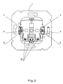
- prinziphaft einen Zusammenbau eines solchen elektrischen Installationsgerätes in der Draufsicht;
- Fig. 3:
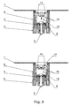
- prinziphaft einen Zusammenbau eines solchen elektrischen Installationsgerätes in der Seitenansicht;
- Fig. 4:
- prinziphaft eine Spreizkralle als Detail;
- Fig. 5:
- prinziphaft die Befestigungsmittel des Gehäuses und des Trägers als Detail.
- Fig. 1:
- in principle, such an electrical installation device spatially in exploded view;
- Fig. 2:
- in principle, an assembly of such an electrical installation device in plan view;
- 3:
- in principle, an assembly of such an electrical installation device in the side view;
- 4:
- in principle a spreader claw as a detail;
- Fig. 5:
- in principle, the fastening means of the housing and the carrier as a detail.
Wie aus den Figuren hervorgeht, besteht ein solches elektrisches Installationsgerät im Wesentlichen aus einem aus Kunststoff bestehenden, zur Aufnahme von Funktionselementen vorgesehenen Gehäuse, an welchem ein Träger 1 und zwei jeweils eine Spreizkralle 2 und eine Spreizschraube 3 aufweisende Befestigungseinrichtungen festgelegt sind. Das Gehäuse weist zur Aufnahme jeder der beiden Befestigungseinrichtungen eine Tasche 4 auf. Das Gehäuse besteht aus einem aus Duroplast gefertigten Sockelteil 5 und einem aus Thermoplast gefertigten Deckelteil 6. An das Sockelteil 5 sind zwei für das direkte Zusammenwirken mit den beiden Spreizkrallen 2 vorgesehene Lageranordnungen 7 angeformt. Weil die beiden Lageranordnungen 7 aus Duroplast bestehen und blockartig ausgeführt sind, ist eine hohe Formstabilität über eine lange Betriebsdauer sichergestellt.As can be seen from the figures, such an electrical installation device consists essentially of a plastic, provided for receiving functional elements housing, on which a
Wie des weiteren insbesondere aus
Wie des weiteren insbesondere aus
Damit die Spreizkrallen 2 in ihrer "Parkposition" nicht über die Kontur des Gehäuses hinausstehen, ist eine versteckte Aufnahme der Krallenarme 9 in entsprechend ausgebildeten Aufnahmeausnehmungen 16 des Gehäuses vorgesehen. Die Aufnahmeausnehmungen 16 sind unterhalb der Tasche 4 bzw. als Ergänzung der Tasche 4 in die Außenwandung des Sockelteils 5 eingeformt. Für jede Spreizkralle 2 sind zwei schlitzartige Aufnahmeausnehmungen 16 vorgesehen. Diese sind so tief ausgeführt, so dass die Krallenarme 9 in ihrer "Parkposition" gänzlich in die Aufnahmeausnehmungen 16 eintauchen. Somit ist sichergestellt, dass zum einen für den Benutzer bzw. Installateur das Verletzungsrisiko bedingt durch die in ihrer "Parkposition" nicht hervorstehende Befestigungskrallen vermieden ist und dass es zum anderen beim Einführen des elektrischen Installationsgerätes in die Installationsdose nicht zu Beschädigungen z. B. von elektrischen Leitern durch die Spreizkrallen 2 kommen kann. Erst wenn sich das elektrische Installationsgerät lagegerecht in der Installationsdose befindet, werden die Spreizkrallen 2 ausgehend von der "Parkposition" in ihre "Festlegungsposition" verstellt, indem die zugeordnete Spreizschraube 3 entsprechend verstellt wird.So that the expanding
Weiterhin ist bei einer solchen Ausführung vorteilhaft, dass auf einfache Art und Weise eine galvanische Trennung zwischen dem Träger 1 und den beiden Befestigungseinrichtungen bzw. Spreizkrallen 2 realisiert ist, weil der Träger 1 nur mit dem aus Thermoplast hergestellten Deckelteil 6 in Verbindung steht und ein entsprechender Isolierabstand von 3 mm zwischen dem Träger 1 und den Spreizkrallen 2 bzw. Spreizschrauben 3 eingehalten wird. Beim vorliegenden Ausführungsbeispiel ist der Träger 1 als sogenannter Tragring ausgeführt und das elektrische Installationsgerät stellt einen Funktionseinsatz für eine Schutzkontaktsteckdose dar. Der erfindungsgemäße Gedanke ist aber auch auf andere elektrische Installationsgeräte, wie z. B. Schalter, Dimmer, Kommunikationsapparate, Busapparate usw. ohne weiteres übertragbar. Auch kann der Träger 1 ohne weiteres als Tragplatte ausgeführt sein.Furthermore, it is advantageous in such a design that a galvanic separation between the
Claims (9)
- Electrical installation device for building system engineering, having a housing made of plastic which comprises a base member (5) and a cover member and is provided for accommodating functional elements and on which a support (1) is located and which is equipped with at least one fastening facility having a claw (2) and an expanding screw (3), with the claw (2) having a flatly-designed base (8) onto which two claw arms (9) extending from the same are integrally formed in such a manner that the claw (2) has a U-shaped contour and that the flatly-designed base (8) cooperates directly with the head (10) of the expanding screw (3) on the one hand and comes to rest directly on a bearing arrangement (7) moulded onto the housing on the other hand, characterised in that the cover member (6) of the housing has a pocket (4) for the purpose of receiving the claw (2) of each fastening facility and that two slit-like receiving recesses (16) corresponding to each claw (2) are moulded into the outer wall of the base member (5) below the pocket (4) for the purpose of accommodating the two claw arms (9), and that a retaining flange (19), which is integrally formed onto the flatly-designed base (8) of each claw (2), forms an operative connection to the associated inner side of one of the two supporting walls (13) moulded onto the cover member (6).
- Electrical installation device according to Claim 1, characterised in that a slit (11) is provided in the flat-designed base (8) of the claw (2), enabling the shank of the expanding screw (3) to pass through.
- Electrical installation device according to Claim 1 or Claim 2, characterised in that the claw arms (9) are integrally formed onto two opposing side areas of the flat-designed base (8) and are arranged extending away from the same.
- Electrical installation device according to any of Claims 1 to 3, characterised in that a stiffening element (20) is moulded onto the front face of the claw (2) between the two claw arms (9).
- Electrical installation device according to any of Claims 1 to 4, characterised in that the housing is at least partially composed of thermoplastic.
- Electrical installation device according to any of Claims 1 to 5, characterised in that the housing is at least partially composed of duroplast.
- Electrical installation device according to any of Claims 1 to 6, characterised in that two supporting walls (13) are moulded onto the housing for the purpose of anchoring the support (1).
- Electrical installation device according to any of Claims 1 to 7, characterised in that fastening means (14, 15) which form an operative connection with each other are moulded onto the housing and onto the support (1).
- Electrical installation device according to any of Claims 1 to 8, characterised in that at least one securing flange (17) assigned to the fastening means (14, 15) is integrally formed onto each of the supporting walls (13) moulded onto the housing.
Priority Applications (1)
| Application Number | Priority Date | Filing Date | Title |
|---|---|---|---|
| PL09002906T PL2124308T3 (en) | 2008-05-16 | 2009-02-28 | Electric installation device |
Applications Claiming Priority (1)
| Application Number | Priority Date | Filing Date | Title |
|---|---|---|---|
| DE102008023983A DE102008023983B4 (en) | 2008-05-16 | 2008-05-16 | Electrical installation device |
Publications (3)
| Publication Number | Publication Date |
|---|---|
| EP2124308A2 EP2124308A2 (en) | 2009-11-25 |
| EP2124308A3 EP2124308A3 (en) | 2012-02-15 |
| EP2124308B1 true EP2124308B1 (en) | 2014-04-30 |
Family
ID=41180476
Family Applications (1)
| Application Number | Title | Priority Date | Filing Date |
|---|---|---|---|
| EP09002906.7A Active EP2124308B1 (en) | 2008-05-16 | 2009-02-28 | Electric installation device |
Country Status (4)
| Country | Link |
|---|---|
| EP (1) | EP2124308B1 (en) |
| DE (1) | DE102008023983B4 (en) |
| ES (1) | ES2480970T3 (en) |
| PL (1) | PL2124308T3 (en) |
Cited By (1)
| Publication number | Priority date | Publication date | Assignee | Title |
|---|---|---|---|---|
| EP3648273A1 (en) | 2018-10-29 | 2020-05-06 | GIRA GIERSIEPEN GmbH & Co. KG | Electrical installation apparatus comprising a claw |
Families Citing this family (2)
| Publication number | Priority date | Publication date | Assignee | Title |
|---|---|---|---|---|
| DE102010036880B4 (en) | 2010-08-06 | 2013-01-17 | Berker Gmbh & Co. Kg | Electrical installation device |
| DE102011050845B3 (en) * | 2011-06-06 | 2012-10-04 | Berker Gmbh & Co. Kg | Method for producing a protective contact clip for a grounded socket and a grounded socket with it |
Family Cites Families (9)
| Publication number | Priority date | Publication date | Assignee | Title |
|---|---|---|---|---|
| EP0240916B1 (en) * | 1986-04-05 | 1991-11-27 | Tehalit GmbH | Domestic installation equipment for cable conduits |
| DE4028766C2 (en) | 1990-09-11 | 1994-05-05 | Berker Geb | Service equipment insert with bracket for expanding claws |
| ES2097424T3 (en) * | 1993-11-12 | 1997-04-01 | Siemens Ag | INSTALLATION DEVICE WITH RETRACTILE EXPANSION CLAWS. |
| FR2770937B1 (en) * | 1997-11-10 | 2000-01-28 | Legrand Sa | BUILT-IN ELECTRICAL APPLIANCE WITH CLAW FIXING |
| DE19812556B4 (en) | 1998-03-21 | 2004-03-11 | Insta Elektro Gmbh | Fastening device for electrical installation devices |
| AT3234U1 (en) * | 1998-11-30 | 1999-11-25 | Legrand Oesterreich | ELECTRICAL INSTALLATION DEVICE |
| DE29901709U1 (en) * | 1999-02-01 | 2000-03-09 | Popp Gmbh & Co Kg | Installation device for electrical installation |
| DE20013233U1 (en) * | 2000-08-01 | 2001-12-13 | Giersiepen Gira Gmbh | Electrical installation device |
| DE10213849A1 (en) * | 2002-03-27 | 2003-10-30 | Siemens Ag | Electrical installation for wall of house is buried in plaster and has upper surface of socket assembly flush with plaster and covered with square plate with tongues bent inward |
-
2008
- 2008-05-16 DE DE102008023983A patent/DE102008023983B4/en not_active Expired - Fee Related
-
2009
- 2009-02-28 PL PL09002906T patent/PL2124308T3/en unknown
- 2009-02-28 ES ES09002906.7T patent/ES2480970T3/en active Active
- 2009-02-28 EP EP09002906.7A patent/EP2124308B1/en active Active
Cited By (1)
| Publication number | Priority date | Publication date | Assignee | Title |
|---|---|---|---|---|
| EP3648273A1 (en) | 2018-10-29 | 2020-05-06 | GIRA GIERSIEPEN GmbH & Co. KG | Electrical installation apparatus comprising a claw |
Also Published As
| Publication number | Publication date |
|---|---|
| EP2124308A3 (en) | 2012-02-15 |
| DE102008023983A1 (en) | 2009-11-19 |
| EP2124308A2 (en) | 2009-11-25 |
| PL2124308T3 (en) | 2014-09-30 |
| DE102008023983B4 (en) | 2013-02-28 |
| ES2480970T3 (en) | 2014-07-29 |
Similar Documents
| Publication | Publication Date | Title |
|---|---|---|
| DE102006022374B4 (en) | switchgear | |
| DE102010060070B4 (en) | Electrical distribution box | |
| DE202014011449U1 (en) | Holding frame for a connector | |
| DE4022876C2 (en) | ||
| DE102007004545A1 (en) | Electrical connection terminal | |
| DE102010003654A1 (en) | Clamp and receiving unit for electronic devices | |
| DE102012206731A1 (en) | Connecting device for a solar module | |
| DE102019216324A1 (en) | EARTH CONNECTING STRUCTURE OF AN ELECTRIC CONNECTING BOX AND FIXING ITEM AND ELECTRIC CONNECTING BOX | |
| EP2124308B1 (en) | Electric installation device | |
| DE102018124583A1 (en) | Terminal arrangement with a busbar | |
| DE102008035722B4 (en) | Electrical / electronic installation device | |
| DE102009060378B3 (en) | Electrical installation device | |
| DE102010036880B4 (en) | Electrical installation device | |
| EP2124307B1 (en) | Electric installation device | |
| DE4017208C2 (en) | Three-phase generator, e.g. for vehicles | |
| DE102011050262B3 (en) | Electrical installation device for building system, has rod-shaped spring element in which receiving bearing which are spaced apart from functional plates are provided at ends | |
| EP2538510B1 (en) | Device holder for underfloor electrical installations | |
| DE102016124609A1 (en) | Distribution box for installation in a wall opening | |
| DE102013109870B3 (en) | Contact assembly for electrical / electronic installation devices | |
| DE102006060231B4 (en) | Electrical / electronic installation device | |
| EP1394916B1 (en) | Apparatus holder for use with electrical trunkings | |
| DE19942803B4 (en) | Electrical installation device | |
| DE102016105899B4 (en) | Electrical power distributor and vehicle electrical system equipped with it | |
| EP3584888A1 (en) | Device plug for inserting into a housing wall and device plug system and electric appliance | |
| WO2012155164A2 (en) | Connection device for electrically connecting a cable, and electric device |
Legal Events
| Date | Code | Title | Description |
|---|---|---|---|
| PUAI | Public reference made under article 153(3) epc to a published international application that has entered the european phase |
Free format text: ORIGINAL CODE: 0009012 |
|
| AK | Designated contracting states |
Kind code of ref document: A2 Designated state(s): AT BE BG CH CY CZ DE DK EE ES FI FR GB GR HR HU IE IS IT LI LT LU LV MC MK MT NL NO PL PT RO SE SI SK TR |
|
| AX | Request for extension of the european patent |
Extension state: AL BA RS |
|
| PUAL | Search report despatched |
Free format text: ORIGINAL CODE: 0009013 |
|
| RIN1 | Information on inventor provided before grant (corrected) |
Inventor name: EICH, WOLFGANG Inventor name: BROECHER, EGON Inventor name: GOEHL, DIETER Inventor name: KIRK, ANNE |
|
| AK | Designated contracting states |
Kind code of ref document: A3 Designated state(s): AT BE BG CH CY CZ DE DK EE ES FI FR GB GR HR HU IE IS IT LI LT LU LV MC MK MT NL NO PL PT RO SE SI SK TR |
|
| AX | Request for extension of the european patent |
Extension state: AL BA RS |
|
| RIC1 | Information provided on ipc code assigned before grant |
Ipc: H02G 3/18 20060101ALN20120112BHEP Ipc: H02G 3/12 20060101AFI20120112BHEP |
|
| 17P | Request for examination filed |
Effective date: 20120307 |
|
| AKX | Designation fees paid |
Designated state(s): AT BE BG CH CY CZ DE DK EE ES FI FR GB GR HR HU IE IS IT LI LT LU LV MC MK MT NL NO PL PT RO SE SI SK TR |
|
| GRAP | Despatch of communication of intention to grant a patent |
Free format text: ORIGINAL CODE: EPIDOSNIGR1 |
|
| RIC1 | Information provided on ipc code assigned before grant |
Ipc: H02G 3/12 20060101AFI20140123BHEP Ipc: H02G 3/18 20060101ALN20140123BHEP |
|
| GRAS | Grant fee paid |
Free format text: ORIGINAL CODE: EPIDOSNIGR3 |
|
| INTG | Intention to grant announced |
Effective date: 20140221 |
|
| GRAA | (expected) grant |
Free format text: ORIGINAL CODE: 0009210 |
|
| AK | Designated contracting states |
Kind code of ref document: B1 Designated state(s): AT BE BG CH CY CZ DE DK EE ES FI FR GB GR HR HU IE IS IT LI LT LU LV MC MK MT NL NO PL PT RO SE SI SK TR |
|
| REG | Reference to a national code |
Ref country code: GB Ref legal event code: FG4D Free format text: NOT ENGLISH Ref country code: CH Ref legal event code: EP |
|
| REG | Reference to a national code |
Ref country code: AT Ref legal event code: REF Ref document number: 665675 Country of ref document: AT Kind code of ref document: T Effective date: 20140515 |
|
| REG | Reference to a national code |
Ref country code: IE Ref legal event code: FG4D Free format text: LANGUAGE OF EP DOCUMENT: GERMAN |
|
| REG | Reference to a national code |
Ref country code: DE Ref legal event code: R096 Ref document number: 502009009270 Country of ref document: DE Effective date: 20140612 |
|
| REG | Reference to a national code |
Ref country code: DE Ref legal event code: R082 Ref document number: 502009009270 Country of ref document: DE Representative=s name: BIENERT, FLORIAN, DIPL.-INF. UNIV., FR Ref country code: DE Ref legal event code: R082 Ref document number: 502009009270 Country of ref document: DE Representative=s name: CABINET NUSS, FR |
|
| REG | Reference to a national code |
Ref country code: DE Ref legal event code: R082 Ref document number: 502009009270 Country of ref document: DE Representative=s name: CABINET NUSS, FR |
|
| REG | Reference to a national code |
Ref country code: ES Ref legal event code: FG2A Ref document number: 2480970 Country of ref document: ES Kind code of ref document: T3 Effective date: 20140729 |
|
| REG | Reference to a national code |
Ref country code: LT Ref legal event code: MG4D |
|
| REG | Reference to a national code |
Ref country code: PL Ref legal event code: T3 |
|
| REG | Reference to a national code |
Ref country code: NL Ref legal event code: VDEP Effective date: 20140430 |
|
| PG25 | Lapsed in a contracting state [announced via postgrant information from national office to epo] |
Ref country code: CY Free format text: LAPSE BECAUSE OF FAILURE TO SUBMIT A TRANSLATION OF THE DESCRIPTION OR TO PAY THE FEE WITHIN THE PRESCRIBED TIME-LIMIT Effective date: 20140430 Ref country code: NO Free format text: LAPSE BECAUSE OF FAILURE TO SUBMIT A TRANSLATION OF THE DESCRIPTION OR TO PAY THE FEE WITHIN THE PRESCRIBED TIME-LIMIT Effective date: 20140730 Ref country code: FI Free format text: LAPSE BECAUSE OF FAILURE TO SUBMIT A TRANSLATION OF THE DESCRIPTION OR TO PAY THE FEE WITHIN THE PRESCRIBED TIME-LIMIT Effective date: 20140430 Ref country code: BG Free format text: LAPSE BECAUSE OF FAILURE TO SUBMIT A TRANSLATION OF THE DESCRIPTION OR TO PAY THE FEE WITHIN THE PRESCRIBED TIME-LIMIT Effective date: 20140730 Ref country code: IS Free format text: LAPSE BECAUSE OF FAILURE TO SUBMIT A TRANSLATION OF THE DESCRIPTION OR TO PAY THE FEE WITHIN THE PRESCRIBED TIME-LIMIT Effective date: 20140830 Ref country code: LT Free format text: LAPSE BECAUSE OF FAILURE TO SUBMIT A TRANSLATION OF THE DESCRIPTION OR TO PAY THE FEE WITHIN THE PRESCRIBED TIME-LIMIT Effective date: 20140430 Ref country code: NL Free format text: LAPSE BECAUSE OF FAILURE TO SUBMIT A TRANSLATION OF THE DESCRIPTION OR TO PAY THE FEE WITHIN THE PRESCRIBED TIME-LIMIT Effective date: 20140430 Ref country code: GR Free format text: LAPSE BECAUSE OF FAILURE TO SUBMIT A TRANSLATION OF THE DESCRIPTION OR TO PAY THE FEE WITHIN THE PRESCRIBED TIME-LIMIT Effective date: 20140731 |
|
| REG | Reference to a national code |
Ref country code: DE Ref legal event code: R082 Ref document number: 502009009270 Country of ref document: DE Representative=s name: CABINET NUSS, FR |
|
| PG25 | Lapsed in a contracting state [announced via postgrant information from national office to epo] |
Ref country code: SE Free format text: LAPSE BECAUSE OF FAILURE TO SUBMIT A TRANSLATION OF THE DESCRIPTION OR TO PAY THE FEE WITHIN THE PRESCRIBED TIME-LIMIT Effective date: 20140430 Ref country code: HR Free format text: LAPSE BECAUSE OF FAILURE TO SUBMIT A TRANSLATION OF THE DESCRIPTION OR TO PAY THE FEE WITHIN THE PRESCRIBED TIME-LIMIT Effective date: 20140430 Ref country code: LV Free format text: LAPSE BECAUSE OF FAILURE TO SUBMIT A TRANSLATION OF THE DESCRIPTION OR TO PAY THE FEE WITHIN THE PRESCRIBED TIME-LIMIT Effective date: 20140430 |
|
| PG25 | Lapsed in a contracting state [announced via postgrant information from national office to epo] |
Ref country code: PT Free format text: LAPSE BECAUSE OF FAILURE TO SUBMIT A TRANSLATION OF THE DESCRIPTION OR TO PAY THE FEE WITHIN THE PRESCRIBED TIME-LIMIT Effective date: 20140901 |
|
| PG25 | Lapsed in a contracting state [announced via postgrant information from national office to epo] |
Ref country code: EE Free format text: LAPSE BECAUSE OF FAILURE TO SUBMIT A TRANSLATION OF THE DESCRIPTION OR TO PAY THE FEE WITHIN THE PRESCRIBED TIME-LIMIT Effective date: 20140430 Ref country code: SK Free format text: LAPSE BECAUSE OF FAILURE TO SUBMIT A TRANSLATION OF THE DESCRIPTION OR TO PAY THE FEE WITHIN THE PRESCRIBED TIME-LIMIT Effective date: 20140430 Ref country code: CZ Free format text: LAPSE BECAUSE OF FAILURE TO SUBMIT A TRANSLATION OF THE DESCRIPTION OR TO PAY THE FEE WITHIN THE PRESCRIBED TIME-LIMIT Effective date: 20140430 Ref country code: DK Free format text: LAPSE BECAUSE OF FAILURE TO SUBMIT A TRANSLATION OF THE DESCRIPTION OR TO PAY THE FEE WITHIN THE PRESCRIBED TIME-LIMIT Effective date: 20140430 Ref country code: RO Free format text: LAPSE BECAUSE OF FAILURE TO SUBMIT A TRANSLATION OF THE DESCRIPTION OR TO PAY THE FEE WITHIN THE PRESCRIBED TIME-LIMIT Effective date: 20140430 |
|
| REG | Reference to a national code |
Ref country code: DE Ref legal event code: R097 Ref document number: 502009009270 Country of ref document: DE |
|
| PLBE | No opposition filed within time limit |
Free format text: ORIGINAL CODE: 0009261 |
|
| STAA | Information on the status of an ep patent application or granted ep patent |
Free format text: STATUS: NO OPPOSITION FILED WITHIN TIME LIMIT |
|
| 26N | No opposition filed |
Effective date: 20150202 |
|
| REG | Reference to a national code |
Ref country code: DE Ref legal event code: R097 Ref document number: 502009009270 Country of ref document: DE Effective date: 20150202 |
|
| PG25 | Lapsed in a contracting state [announced via postgrant information from national office to epo] |
Ref country code: BE Free format text: LAPSE BECAUSE OF NON-PAYMENT OF DUE FEES Effective date: 20150228 |
|
| PG25 | Lapsed in a contracting state [announced via postgrant information from national office to epo] |
Ref country code: SI Free format text: LAPSE BECAUSE OF FAILURE TO SUBMIT A TRANSLATION OF THE DESCRIPTION OR TO PAY THE FEE WITHIN THE PRESCRIBED TIME-LIMIT Effective date: 20140430 |
|
| PG25 | Lapsed in a contracting state [announced via postgrant information from national office to epo] |
Ref country code: LU Free format text: LAPSE BECAUSE OF FAILURE TO SUBMIT A TRANSLATION OF THE DESCRIPTION OR TO PAY THE FEE WITHIN THE PRESCRIBED TIME-LIMIT Effective date: 20150228 |
|
| REG | Reference to a national code |
Ref country code: CH Ref legal event code: PL |
|
| GBPC | Gb: european patent ceased through non-payment of renewal fee |
Effective date: 20150228 |
|
| PG25 | Lapsed in a contracting state [announced via postgrant information from national office to epo] |
Ref country code: LI Free format text: LAPSE BECAUSE OF NON-PAYMENT OF DUE FEES Effective date: 20150228 Ref country code: MC Free format text: LAPSE BECAUSE OF FAILURE TO SUBMIT A TRANSLATION OF THE DESCRIPTION OR TO PAY THE FEE WITHIN THE PRESCRIBED TIME-LIMIT Effective date: 20140430 Ref country code: CH Free format text: LAPSE BECAUSE OF NON-PAYMENT OF DUE FEES Effective date: 20150228 |
|
| REG | Reference to a national code |
Ref country code: IE Ref legal event code: MM4A |
|
| REG | Reference to a national code |
Ref country code: FR Ref legal event code: PLFP Year of fee payment: 8 |
|
| PG25 | Lapsed in a contracting state [announced via postgrant information from national office to epo] |
Ref country code: IE Free format text: LAPSE BECAUSE OF NON-PAYMENT OF DUE FEES Effective date: 20150228 Ref country code: GB Free format text: LAPSE BECAUSE OF NON-PAYMENT OF DUE FEES Effective date: 20150228 |
|
| PG25 | Lapsed in a contracting state [announced via postgrant information from national office to epo] |
Ref country code: MT Free format text: LAPSE BECAUSE OF FAILURE TO SUBMIT A TRANSLATION OF THE DESCRIPTION OR TO PAY THE FEE WITHIN THE PRESCRIBED TIME-LIMIT Effective date: 20140430 |
|
| REG | Reference to a national code |
Ref country code: FR Ref legal event code: PLFP Year of fee payment: 9 |
|
| PG25 | Lapsed in a contracting state [announced via postgrant information from national office to epo] |
Ref country code: HU Free format text: LAPSE BECAUSE OF FAILURE TO SUBMIT A TRANSLATION OF THE DESCRIPTION OR TO PAY THE FEE WITHIN THE PRESCRIBED TIME-LIMIT; INVALID AB INITIO Effective date: 20090228 |
|
| PG25 | Lapsed in a contracting state [announced via postgrant information from national office to epo] |
Ref country code: TR Free format text: LAPSE BECAUSE OF FAILURE TO SUBMIT A TRANSLATION OF THE DESCRIPTION OR TO PAY THE FEE WITHIN THE PRESCRIBED TIME-LIMIT Effective date: 20140430 |
|
| REG | Reference to a national code |
Ref country code: FR Ref legal event code: PLFP Year of fee payment: 10 |
|
| PG25 | Lapsed in a contracting state [announced via postgrant information from national office to epo] |
Ref country code: MK Free format text: LAPSE BECAUSE OF FAILURE TO SUBMIT A TRANSLATION OF THE DESCRIPTION OR TO PAY THE FEE WITHIN THE PRESCRIBED TIME-LIMIT Effective date: 20140430 |
|
| PGFP | Annual fee paid to national office [announced via postgrant information from national office to epo] |
Ref country code: DE Payment date: 20220225 Year of fee payment: 14 Ref country code: AT Payment date: 20220202 Year of fee payment: 14 |
|
| PGFP | Annual fee paid to national office [announced via postgrant information from national office to epo] |
Ref country code: PL Payment date: 20220202 Year of fee payment: 14 Ref country code: IT Payment date: 20220222 Year of fee payment: 14 Ref country code: FR Payment date: 20220223 Year of fee payment: 14 Ref country code: ES Payment date: 20220301 Year of fee payment: 14 |
|
| REG | Reference to a national code |
Ref country code: DE Ref legal event code: R119 Ref document number: 502009009270 Country of ref document: DE |
|
| REG | Reference to a national code |
Ref country code: AT Ref legal event code: MM01 Ref document number: 665675 Country of ref document: AT Kind code of ref document: T Effective date: 20230228 |
|
| PG25 | Lapsed in a contracting state [announced via postgrant information from national office to epo] |
Ref country code: AT Free format text: LAPSE BECAUSE OF NON-PAYMENT OF DUE FEES Effective date: 20230228 |
|
| PG25 | Lapsed in a contracting state [announced via postgrant information from national office to epo] |
Ref country code: IT Free format text: LAPSE BECAUSE OF NON-PAYMENT OF DUE FEES Effective date: 20230228 Ref country code: FR Free format text: LAPSE BECAUSE OF NON-PAYMENT OF DUE FEES Effective date: 20230228 Ref country code: DE Free format text: LAPSE BECAUSE OF NON-PAYMENT OF DUE FEES Effective date: 20230901 |