EP2123926A1 - Boot for a constant velocity joint - Google Patents
Boot for a constant velocity joint Download PDFInfo
- Publication number
- EP2123926A1 EP2123926A1 EP09160410A EP09160410A EP2123926A1 EP 2123926 A1 EP2123926 A1 EP 2123926A1 EP 09160410 A EP09160410 A EP 09160410A EP 09160410 A EP09160410 A EP 09160410A EP 2123926 A1 EP2123926 A1 EP 2123926A1
- Authority
- EP
- European Patent Office
- Prior art keywords
- joint member
- boot
- outer joint
- insert
- end portion
- Prior art date
- Legal status (The legal status is an assumption and is not a legal conclusion. Google has not performed a legal analysis and makes no representation as to the accuracy of the status listed.)
- Granted
Links
- 239000000463 material Substances 0.000 claims description 15
- 230000000452 restraining effect Effects 0.000 claims description 11
- 239000013536 elastomeric material Substances 0.000 claims description 2
- 239000007769 metal material Substances 0.000 claims description 2
- 239000004033 plastic Substances 0.000 claims description 2
- 239000012815 thermoplastic material Substances 0.000 claims description 2
- 230000007423 decrease Effects 0.000 description 3
- 238000005096 rolling process Methods 0.000 description 2
- 230000001419 dependent effect Effects 0.000 description 1
- 230000004048 modification Effects 0.000 description 1
- 238000012986 modification Methods 0.000 description 1
- 238000000465 moulding Methods 0.000 description 1
Images
Classifications
-
- F—MECHANICAL ENGINEERING; LIGHTING; HEATING; WEAPONS; BLASTING
- F16—ENGINEERING ELEMENTS AND UNITS; GENERAL MEASURES FOR PRODUCING AND MAINTAINING EFFECTIVE FUNCTIONING OF MACHINES OR INSTALLATIONS; THERMAL INSULATION IN GENERAL
- F16D—COUPLINGS FOR TRANSMITTING ROTATION; CLUTCHES; BRAKES
- F16D3/00—Yielding couplings, i.e. with means permitting movement between the connected parts during the drive
- F16D3/84—Shrouds, e.g. casings, covers; Sealing means specially adapted therefor
- F16D3/843—Shrouds, e.g. casings, covers; Sealing means specially adapted therefor enclosed covers
- F16D3/845—Shrouds, e.g. casings, covers; Sealing means specially adapted therefor enclosed covers allowing relative movement of joint parts due to the flexing of the cover
-
- F—MECHANICAL ENGINEERING; LIGHTING; HEATING; WEAPONS; BLASTING
- F16—ENGINEERING ELEMENTS AND UNITS; GENERAL MEASURES FOR PRODUCING AND MAINTAINING EFFECTIVE FUNCTIONING OF MACHINES OR INSTALLATIONS; THERMAL INSULATION IN GENERAL
- F16D—COUPLINGS FOR TRANSMITTING ROTATION; CLUTCHES; BRAKES
- F16D3/00—Yielding couplings, i.e. with means permitting movement between the connected parts during the drive
- F16D3/16—Universal joints in which flexibility is produced by means of pivots or sliding or rolling connecting parts
- F16D3/20—Universal joints in which flexibility is produced by means of pivots or sliding or rolling connecting parts one coupling part entering a sleeve of the other coupling part and connected thereto by sliding or rolling members
- F16D3/22—Universal joints in which flexibility is produced by means of pivots or sliding or rolling connecting parts one coupling part entering a sleeve of the other coupling part and connected thereto by sliding or rolling members the rolling members being balls, rollers, or the like, guided in grooves or sockets in both coupling parts
- F16D3/223—Universal joints in which flexibility is produced by means of pivots or sliding or rolling connecting parts one coupling part entering a sleeve of the other coupling part and connected thereto by sliding or rolling members the rolling members being balls, rollers, or the like, guided in grooves or sockets in both coupling parts the rolling members being guided in grooves in both coupling parts
-
- Y—GENERAL TAGGING OF NEW TECHNOLOGICAL DEVELOPMENTS; GENERAL TAGGING OF CROSS-SECTIONAL TECHNOLOGIES SPANNING OVER SEVERAL SECTIONS OF THE IPC; TECHNICAL SUBJECTS COVERED BY FORMER USPC CROSS-REFERENCE ART COLLECTIONS [XRACs] AND DIGESTS
- Y10—TECHNICAL SUBJECTS COVERED BY FORMER USPC
- Y10S—TECHNICAL SUBJECTS COVERED BY FORMER USPC CROSS-REFERENCE ART COLLECTIONS [XRACs] AND DIGESTS
- Y10S464/00—Rotary shafts, gudgeons, housings, and flexible couplings for rotary shafts
- Y10S464/904—Homokinetic coupling
- Y10S464/906—Torque transmitted via radially spaced balls
Definitions
- the subject invention relates to a constant velocity joint assembly, and more specifically to a boot for a constant velocity joint assembly.
- Constant velocity joints are typically employed in automotive axial drive shafts, and especially in front-wheel-drive vehicles between the transaxle differential and the driving wheel.
- the constant velocity joints transmit a torque at various speeds, angles and telescopic positions between a first shaft and a second shaft.
- the constant velocity joint includes an outer joint member and an inner joint member.
- the first shaft is coupled to the inner joint member and the second shaft is coupled to the outer joint member.
- the first shaft and the second shaft may be integrally formed with the inner joint member and/or the outer joint member respectively.
- the outer joint member defines a cavity, and includes an axial end disposed along a longitudinal axis.
- the inner joint member is disposed within the cavity, and is moveable with the first shaft relative to the outer joint member for articulated movement relative to the outer joint member.
- the constant velocity joint includes a flexible boot.
- the boot seals the cavity from dirt and debris.
- the boot is typically coupled to the first shaft and to the outer joint member of the constant velocity joint.
- Aucktor style constant velocity joints include a plurality of drive balls disposed between pairs of opposing grooves defined by the outer joint member and the inner joint member.
- an articulation limiting device commonly referred to as a can
- the articulation limiting device may extend outward along the longitudinal axis away from the axial end of the outer joint member or may extend radially inward toward the longitudinal axis to limit articulation of the first shaft member and prevent disassembly of the constant velocity joint.
- the boot is coupled to the outer joint member via the articulation limiting device, i.e., the boot is attached to the articulation limiting device, and the articulation limiting device is attached to the outer joint member.
- the subject invention provides a constant velocity joint assembly.
- the constant velocity joint assembly comprises an outer joint member and an inner joint member.
- the outer joint member defines a cavity, and includes an axial end disposed along a longitudinal axis of the outer joint member.
- the inner joint member is disposed within the cavity.
- the inner joint member is moveable relative to the outer joint member.
- a shaft is coupled to the inner joint member.
- the shaft is moveable with the inner joint member for articulated movement of the shaft and the inner joint member relative to the outer joint member.
- a boot seals the cavity.
- the boot comprises a first end portion connected to the shaft, and a second end portion connected to the outer joint member.
- a bellows portion extends between the first end portion and the second end portion.
- An insert is supported by the boot and positioned by the boot adjacent to and in abutting engagement with the axial end of the outer joint member.
- the insert limits the articulated movement of the shaft and the inner joint member relative to the outer joint member to prevent disengagement of the inner joint member from the outer joint member.
- the subject invention incorporates the insert into the boot.
- the boot positions and secures the insert relative to the outer joint member.
- the insert is not directly connected to the outer joint member, but is secured in place relative to the outer joint member by the boot.
- the boot is directly connected to the shaft and the outer joint member. Therefore, assembly of the constant velocity joint only requires attaching the boot to the outer joint member, thereby eliminating the can utilized in the prior art and the connection thereof, and simplifying the assembly of the constant velocity joint.
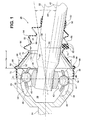
- Figure 1 is a cross sectional view of a constant velocity joint assembly.
- a constant velocity joint assembly is shown generally at 20.
- the constant velocity joint assembly 20 transmits a torque at various speeds, angles and telescopic positions between a first shaft 22 and a second shaft 24.
- the constant velocity joint assembly 20 is typically employed in automotive axial drive shafts, and especially in front-wheel-drive vehicles between a transaxle differential and a driving wheel. However, it should be appreciated that the constant velocity joint assembly 20 may be utilized in other applications not described herein.
- the constant velocity joint assembly 20 includes an outer joint member 26 and an inner joint member 28.
- the first shaft 22 is coupled to the inner joint member 28, and the second shaft 24 is coupled to the outer joint member 26.
- the first shaft 22 is coupled to the inner joint member 28 via a splined connection therebetween, in which the inner joint member 28 defines a splined aperture and the first shaft 22 defines a splined end in interlocking engagement with the splined aperture.
- the first shaft 22 and the inner joint member 28 may be coupled together in some other manner not shown or described herein. It should also be appreciated that the first shaft 22 and the inner joint member 28 may be integrally formed together as a single component.
- the second shaft 24 and the outer joint member 26 are integrally formed together as a single component.
- the outer joint member 26 and the second shaft 24 may be separate components coupled together via a suitable connection, such as through a plurality of fasteners.
- the outer joint member 26 defines a cavity 30, and includes an axial end 32 disposed along a longitudinal axis 34 of the outer joint member 26.
- the axial end 32 of the outer joint member 26 is the end surface of the outer joint member 26, which is disposed generally perpendicular and transverse to the longitudinal axis 34 of the outer joint member 26.
- the inner joint member 28 is disposed within the cavity 30 of the outer joint member 26.
- the inner joint member 28 is moveable relative to the outer joint member 26.
- the first shaft 22 is moveable with the inner joint member 28 for articulated movement of the shaft and the inner joint member 28 relative to the outer joint member 26.
- the first shaft 22 and the inner joint member 28 are freely moveable relative to the outer joint member 26 within a pre-determined range of articulation 36.
- the pre-determined range of articulation 36 is measured relative to the longitudinal axis 34, and delimits the maximum desirable operating range of the constant velocity joint assembly 20. Accordingly, it should be appreciated that articulation of the first shaft 22 and the inner member beyond the pre-determined range of articulation 36 may result in disengagement or disassembly of the inner joint member 28 from the outer joint member 26.
- the constant velocity joint assembly 20 includes an Aucktor style constant velocity joint.
- the constant velocity joint assembly 20 member may include some other style of constant velocity joint not shown or described herein, and is not limited to the specific embodiment shown and described herein.
- the outer joint member 26 defines a plurality of outer grooves 38.
- the outer grooves 38 are radially disposed about and extend along the longitudinal axis 34.
- the inner joint member 28 extends along a shaft axis 40.
- the inner joint member 28 defines a plurality of inner grooves 42.
- the inner grooves 42 are radially disposed about and extend along the shaft axis 40.
- Each of the plurality of inner grooves 42 is disposed in opposition to one of the plurality of outer grooves 38. Accordingly, each of the plurality of inner grooves 42 cooperates with one of the plurality of outer grooves 38 to define a funnel.
- the constant velocity joint assembly 20 further comprises a plurality of drive balls 44.
- One of the drive balls 44 is partially disposed in rolling engagement within one of the inner grooves 42, and is also partially disposed in rolling engagement within one of the outer grooves 38.
- the drive balls 44 transmit a torque between the outer joint member 26 and the inner joint member 28.
- the drive balls 44 roll along the inner grooves 42 and the outer grooves 38 as the first shaft 22 and the inner joint member 28 articulate relative to the outer joint member 26.
- a cage 46 is disposed between the inner joint member 28 and the outer joint member 26.
- the cage 46 defines a plurality of windows 48 with one of the plurality of drive balls 44 disposed within each of the plurality of windows 48.
- the cage 46 positions the drive balls 44 within a plane and steers the drive balls 44 as a unit as the first shaft 22 and the inner joint member 28 articulate relative to the outer joint member 26.
- the constant velocity joint assembly 20 further includes a boot 50.
- the boot 50 seals the cavity 30 from dirt and debris.
- the boot 50 includes a flexible material chosen from a group of materials comprising, but not limited too, an elastomeric material and a thermoplastic material. It should be appreciated that the flexible material may include some other material not described herein.
- the boot 50 includes a first end portion 52 connected to the first shaft 22, a second end portion 54 connected to the outer joint member 26 and a bellows portion 56 extending between the first end portion 52 and the second end portion 54 .
- a first clamp 58 is in clamping engagement with the first end portion 52 of the boot 50.
- the first clamp 58 secures the first end portion 52 of the boot 50 to the first shaft 22.
- a second clamp 60 is in clamping engagement with the second end portion 54 of the boot 50.
- the second clamp 60 secures the second end portion 54 of the boot 50 to the outer joint member 26.
- some other device and or interlocking configuration not shown or described herein may be utilized to secure the first end portion 52 and the second end portion 54 to the first shaft 22 and the outer joint member 26 respectively.
- the bellows portion 56 of the boot 50 includes a plurality of convolutions 62.
- the convolutions define a plurality of alternating crests 64 and valleys 66.
- the plurality of convolutions 62 includes a first convolute 68 disposed adjacent and nearest to the second end portion 54 of the boot 50.
- the first convolute 68 defines a first valley 70.
- the first convolute 68 extends from the second end portion 54 of the boot 50 to the first valley 70.
- the first valley 70 is disposed adjacent the second end portion 54 of the boot 50, near the axial end 32 of the outer joint member 26.
- the boot 50 further includes an insert 72.
- the insert 72 is supported by the boot 50 and is positioned by the boot 50 adjacent to and in abutting engagement with the axial end 32 of the outer joint member 26.
- the insert 72 is not directly connected to the outer joint member 26, but rather is connected to the boot 50 with the boot 50 securing the position of the insert 72 relative to the outer joint member 26.
- the insert 72 preferably includes a rigid material.
- the rigid material may be chosen from, but is not limited too, a group of materials comprising a plastic material and a metal material. It should be appreciated that the rigid material may include some other material not described herein.
- the insert 72 preferably extends a pre-determined length 74 from the axial end 32 of the outer joint member 26 along the longitudinal axis 34 toward the first end portion 52 of the boot 50.
- the insert 72 extends the pre-determined length 74 along the longitudinal axis 34 from the axial end 32 of the outer joint member 26 to the first valley 70 of the first convolute 68.
- the insert 72 is substantially tubular or cylindrical, and preferably includes a truncated conical shape along the longitudinal axis 34.
- the insert 72 includes a support end 76 and a restraining end 78.
- the support end 76 abuts the axial end 32 of the outer joint member 26.
- the restraining end 78 is axially spaced from the support end 76 along the longitudinal axis 34.
- the restraining end 78 defines a first diameter 80.
- the support end 76 defines a second diameter 82 larger than the first diameter 80.
- the first diameter 80 and the second diameter 82 cooperate to define the truncated conical shape.
- the second diameter 82 of the support end 76 is approximately sized to mate with the axial end 32 of the outer joint member 26.
- the restraining end 78 of the insert 72 and the first valley 70 are adjacent each other and aligned along the longitudinal axis 34.
- the first convolute 68 includes a thickened cross section relative to a remainder of the bellows portion 56 of the boot 50.
- the first convolute 68, between the second end portion 54 and the first valley 70 is thicker than the rest of the bellows portion 56 of the boot 50. This thickened section increases the rigidity of the boot 50 and assists in securing the insert 72 in place relative to the outer joint member 26.
- the boot 50 defines an interior 84, with the insert 72 being disposed within the interior 84 of the boot 50.
- the boot 50 defines an annular groove 86 extending radially outward relative to the longitudinal axis 34.
- the annular groove 86 is disposed adjacent the second end portion 54 of the boot 50, adjacent the axial end 32 of the outer joint member 26.
- the insert 72 includes a radial flange 88 extending radially outward from the longitudinal axis 34.
- the radial flange 88 is disposed on the support end 76 of the insert 72.
- the radial flange 88 is disposed within the annular groove 86 of the boot 50 to position the insert 72 within the boot 50 relative to the outer joint member 26.
- the annular flange is in interlocking engagement with the annular groove 86 such that the insert 72 is prevented from moving within the boot 50, and is thereby secured in place by the boot 50 relative to the outer joint member 26.
- the boot 50 and the insert 72 may be configured in some other manner not shown or described herein to achieve an interlocking engagement therebetween.
- the boot 50 may be formed by molding around the insert 72.
- the insert 72 limits the articulated movement of the shaft and the inner joint member 28 relative to the outer joint member 26 to within the pre-determined range of articulation 36 to prevent disengagement and/or disassembly of the inner joint member 28 from the outer joint member 26.
- the range of articulation 36 is dependent upon the first diameter 80 of the restraining end 78 and the pre-determined length 74 of the insert 72.
- the range of articulation 36 is adjusted by modifying either of the first diameter 80 of the restraining end 78 and/or the pre-determined length 74 of the insert 72.
- the range of articulation 36 increases with an increase in the first diameter 80 of the restraining end 78 and/or with a decrease in the pre-determined length 74 of the insert 72.
- the range of articulation 36 decreases with a decrease in the first diameter 80 of the restraining end 78 and/or with an increase in the pre-determine length of the insert 72.
Landscapes
- Engineering & Computer Science (AREA)
- General Engineering & Computer Science (AREA)
- Mechanical Engineering (AREA)
- Diaphragms And Bellows (AREA)
- Sealing Devices (AREA)
- Joints Allowing Movement (AREA)
Abstract
Description
- The subject invention relates to a constant velocity joint assembly, and more specifically to a boot for a constant velocity joint assembly.
- Constant velocity joints are typically employed in automotive axial drive shafts, and especially in front-wheel-drive vehicles between the transaxle differential and the driving wheel. The constant velocity joints transmit a torque at various speeds, angles and telescopic positions between a first shaft and a second shaft.
- Many styles of constant velocity joints exist. Often, the constant velocity joint includes an outer joint member and an inner joint member. The first shaft is coupled to the inner joint member and the second shaft is coupled to the outer joint member. The first shaft and the second shaft may be integrally formed with the inner joint member and/or the outer joint member respectively. The outer joint member defines a cavity, and includes an axial end disposed along a longitudinal axis. The inner joint member is disposed within the cavity, and is moveable with the first shaft relative to the outer joint member for articulated movement relative to the outer joint member.
- Typically, the constant velocity joint includes a flexible boot. The boot seals the cavity from dirt and debris. The boot is typically coupled to the first shaft and to the outer joint member of the constant velocity joint.
- Many styles of the constant velocity joint are sensitive to over-articulation, and disassembly in response to over-articulation beyond a pre-determined maximum range of articulation. One such style of constant velocity joint that is subject of disassembly in response to over-articulation is commonly known as an Aucktor style constant velocity joint. Aucktor style constant velocity joints include a plurality of drive balls disposed between pairs of opposing grooves defined by the outer joint member and the inner joint member.
- In order to prevent over-articulation of constant velocity joints, such as the Aucktor style constant velocity joint, it is known to attach an articulation limiting device, commonly referred to as a can, directly to the outer joint member. The articulation limiting device may extend outward along the longitudinal axis away from the axial end of the outer joint member or may extend radially inward toward the longitudinal axis to limit articulation of the first shaft member and prevent disassembly of the constant velocity joint. The boot is coupled to the outer joint member via the articulation limiting device, i.e., the boot is attached to the articulation limiting device, and the articulation limiting device is attached to the outer joint member.
- There remains a need to reduce the cost of the constant velocity joints while increasing the speed of assembling the constant velocity joints.
- The subject invention provides a constant velocity joint assembly. The constant velocity joint assembly comprises an outer joint member and an inner joint member. The outer joint member defines a cavity, and includes an axial end disposed along a longitudinal axis of the outer joint member. The inner joint member is disposed within the cavity. The inner joint member is moveable relative to the outer joint member. A shaft is coupled to the inner joint member. The shaft is moveable with the inner joint member for articulated movement of the shaft and the inner joint member relative to the outer joint member. A boot seals the cavity. The boot comprises a first end portion connected to the shaft, and a second end portion connected to the outer joint member. A bellows portion extends between the first end portion and the second end portion. An insert is supported by the boot and positioned by the boot adjacent to and in abutting engagement with the axial end of the outer joint member. The insert limits the articulated movement of the shaft and the inner joint member relative to the outer joint member to prevent disengagement of the inner joint member from the outer joint member.
- Accordingly, the subject invention incorporates the insert into the boot. The boot positions and secures the insert relative to the outer joint member. As such, the insert is not directly connected to the outer joint member, but is secured in place relative to the outer joint member by the boot. The boot is directly connected to the shaft and the outer joint member. Therefore, assembly of the constant velocity joint only requires attaching the boot to the outer joint member, thereby eliminating the can utilized in the prior art and the connection thereof, and simplifying the assembly of the constant velocity joint.
- Other advantages of the present invention will be readily appreciated, as the same becomes better understood by reference to the following detailed description when considered in connection with the accompanying drawings.
Figure 1 is a cross sectional view of a constant velocity joint assembly. - Referring to the Figures, wherein like numerals indicate corresponding parts throughout the several views, a constant velocity joint assembly is shown generally at 20. The constant
velocity joint assembly 20 transmits a torque at various speeds, angles and telescopic positions between afirst shaft 22 and asecond shaft 24. - The constant
velocity joint assembly 20 is typically employed in automotive axial drive shafts, and especially in front-wheel-drive vehicles between a transaxle differential and a driving wheel. However, it should be appreciated that the constantvelocity joint assembly 20 may be utilized in other applications not described herein. - The constant
velocity joint assembly 20 includes anouter joint member 26 and aninner joint member 28. Thefirst shaft 22 is coupled to theinner joint member 28, and thesecond shaft 24 is coupled to the outerjoint member 26. Preferably, thefirst shaft 22 is coupled to the innerjoint member 28 via a splined connection therebetween, in which the innerjoint member 28 defines a splined aperture and thefirst shaft 22 defines a splined end in interlocking engagement with the splined aperture. Alternatively, thefirst shaft 22 and the innerjoint member 28 may be coupled together in some other manner not shown or described herein. It should also be appreciated that thefirst shaft 22 and the innerjoint member 28 may be integrally formed together as a single component. Preferably, thesecond shaft 24 and theouter joint member 26 are integrally formed together as a single component. However, it should be appreciated that the outerjoint member 26 and thesecond shaft 24 may be separate components coupled together via a suitable connection, such as through a plurality of fasteners. - The outer
joint member 26 defines acavity 30, and includes anaxial end 32 disposed along alongitudinal axis 34 of theouter joint member 26. Theaxial end 32 of theouter joint member 26 is the end surface of theouter joint member 26, which is disposed generally perpendicular and transverse to thelongitudinal axis 34 of theouter joint member 26. The innerjoint member 28 is disposed within thecavity 30 of theouter joint member 26. The innerjoint member 28 is moveable relative to the outerjoint member 26. As such, thefirst shaft 22 is moveable with the innerjoint member 28 for articulated movement of the shaft and the innerjoint member 28 relative to the outerjoint member 26. - The
first shaft 22 and the innerjoint member 28 are freely moveable relative to the outerjoint member 26 within a pre-determined range ofarticulation 36. The pre-determined range ofarticulation 36 is measured relative to thelongitudinal axis 34, and delimits the maximum desirable operating range of the constantvelocity joint assembly 20. Accordingly, it should be appreciated that articulation of thefirst shaft 22 and the inner member beyond the pre-determined range ofarticulation 36 may result in disengagement or disassembly of the innerjoint member 28 from the outerjoint member 26. - As shown and described herein, the constant
velocity joint assembly 20 includes an Aucktor style constant velocity joint. However, it should be appreciated that the constantvelocity joint assembly 20 member may include some other style of constant velocity joint not shown or described herein, and is not limited to the specific embodiment shown and described herein. As shown, the outerjoint member 26 defines a plurality ofouter grooves 38. Theouter grooves 38 are radially disposed about and extend along thelongitudinal axis 34. The innerjoint member 28 extends along ashaft axis 40. The innerjoint member 28 defines a plurality ofinner grooves 42. Theinner grooves 42 are radially disposed about and extend along theshaft axis 40. Each of the plurality ofinner grooves 42 is disposed in opposition to one of the plurality ofouter grooves 38. Accordingly, each of the plurality ofinner grooves 42 cooperates with one of the plurality ofouter grooves 38 to define a funnel. - The constant velocity
joint assembly 20 further comprises a plurality ofdrive balls 44. One of thedrive balls 44 is partially disposed in rolling engagement within one of theinner grooves 42, and is also partially disposed in rolling engagement within one of theouter grooves 38. Thedrive balls 44 transmit a torque between the outerjoint member 26 and the innerjoint member 28. Thedrive balls 44 roll along theinner grooves 42 and theouter grooves 38 as thefirst shaft 22 and the innerjoint member 28 articulate relative to the outerjoint member 26. - A
cage 46 is disposed between the innerjoint member 28 and the outerjoint member 26. Thecage 46 defines a plurality ofwindows 48 with one of the plurality ofdrive balls 44 disposed within each of the plurality ofwindows 48. Thecage 46 positions thedrive balls 44 within a plane and steers thedrive balls 44 as a unit as thefirst shaft 22 and the innerjoint member 28 articulate relative to the outerjoint member 26. - The constant velocity
joint assembly 20 further includes aboot 50. Theboot 50 seals thecavity 30 from dirt and debris. Theboot 50 includes a flexible material chosen from a group of materials comprising, but not limited too, an elastomeric material and a thermoplastic material. It should be appreciated that the flexible material may include some other material not described herein. - The
boot 50 includes afirst end portion 52 connected to thefirst shaft 22, asecond end portion 54 connected to the outerjoint member 26 and abellows portion 56 extending between thefirst end portion 52 and thesecond end portion 54. - Preferably, a
first clamp 58 is in clamping engagement with thefirst end portion 52 of theboot 50. Thefirst clamp 58 secures thefirst end portion 52 of theboot 50 to thefirst shaft 22. Asecond clamp 60 is in clamping engagement with thesecond end portion 54 of theboot 50. Thesecond clamp 60 secures thesecond end portion 54 of theboot 50 to the outerjoint member 26. Alternatively, it should be appreciated that some other device and or interlocking configuration not shown or described herein may be utilized to secure thefirst end portion 52 and thesecond end portion 54 to thefirst shaft 22 and the outerjoint member 26 respectively. - The
bellows portion 56 of theboot 50 includes a plurality ofconvolutions 62. The convolutions define a plurality of alternatingcrests 64 andvalleys 66. The plurality ofconvolutions 62 includes a first convolute 68 disposed adjacent and nearest to thesecond end portion 54 of theboot 50. The first convolute 68 defines afirst valley 70. The first convolute 68 extends from thesecond end portion 54 of theboot 50 to thefirst valley 70. Thefirst valley 70 is disposed adjacent thesecond end portion 54 of theboot 50, near theaxial end 32 of the outerjoint member 26. - The
boot 50 further includes aninsert 72. Theinsert 72 is supported by theboot 50 and is positioned by theboot 50 adjacent to and in abutting engagement with theaxial end 32 of the outerjoint member 26. Notably, theinsert 72 is not directly connected to the outerjoint member 26, but rather is connected to theboot 50 with theboot 50 securing the position of theinsert 72 relative to the outerjoint member 26. - The
insert 72 preferably includes a rigid material. The rigid material may be chosen from, but is not limited too, a group of materials comprising a plastic material and a metal material. It should be appreciated that the rigid material may include some other material not described herein. - The
insert 72 preferably extends apre-determined length 74 from theaxial end 32 of the outerjoint member 26 along thelongitudinal axis 34 toward thefirst end portion 52 of theboot 50. Preferably, theinsert 72 extends thepre-determined length 74 along thelongitudinal axis 34 from theaxial end 32 of the outerjoint member 26 to thefirst valley 70 of the first convolute 68. - The
insert 72 is substantially tubular or cylindrical, and preferably includes a truncated conical shape along thelongitudinal axis 34. Theinsert 72 includes asupport end 76 and a restrainingend 78. Thesupport end 76 abuts theaxial end 32 of the outerjoint member 26. The restrainingend 78 is axially spaced from thesupport end 76 along thelongitudinal axis 34. The restrainingend 78 defines afirst diameter 80. Thesupport end 76 defines asecond diameter 82 larger than thefirst diameter 80. Thefirst diameter 80 and thesecond diameter 82 cooperate to define the truncated conical shape. - The
second diameter 82 of thesupport end 76 is approximately sized to mate with theaxial end 32 of the outerjoint member 26. Upon thefirst shaft 22 articulating about thelongitudinal axis 34 up to the maximum articulation defined by the pre-determined range ofarticulation 36, thefirst shaft 22 contacts the restrainingend 78 of theinsert 72, which restricts further articulation beyond the pre-determined range ofarticulation 36. - Preferably, the restraining
end 78 of theinsert 72 and thefirst valley 70 are adjacent each other and aligned along thelongitudinal axis 34. Also preferably, but not necessarily, the first convolute 68 includes a thickened cross section relative to a remainder of thebellows portion 56 of theboot 50. In other words, the first convolute 68, between thesecond end portion 54 and thefirst valley 70, is thicker than the rest of thebellows portion 56 of theboot 50. This thickened section increases the rigidity of theboot 50 and assists in securing theinsert 72 in place relative to the outerjoint member 26. - The
boot 50 defines an interior 84, with theinsert 72 being disposed within theinterior 84 of theboot 50. Theboot 50 defines anannular groove 86 extending radially outward relative to thelongitudinal axis 34. Theannular groove 86 is disposed adjacent thesecond end portion 54 of theboot 50, adjacent theaxial end 32 of the outerjoint member 26. Theinsert 72 includes aradial flange 88 extending radially outward from thelongitudinal axis 34. Theradial flange 88 is disposed on thesupport end 76 of theinsert 72. Theradial flange 88 is disposed within theannular groove 86 of theboot 50 to position theinsert 72 within theboot 50 relative to the outerjoint member 26. Accordingly, the annular flange is in interlocking engagement with theannular groove 86 such that theinsert 72 is prevented from moving within theboot 50, and is thereby secured in place by theboot 50 relative to the outerjoint member 26. It should be appreciated that theboot 50 and theinsert 72 may be configured in some other manner not shown or described herein to achieve an interlocking engagement therebetween. As an example, theboot 50 may be formed by molding around theinsert 72. - As described above, the
insert 72 limits the articulated movement of the shaft and the innerjoint member 28 relative to the outerjoint member 26 to within the pre-determined range ofarticulation 36 to prevent disengagement and/or disassembly of the innerjoint member 28 from the outerjoint member 26. The range ofarticulation 36 is dependent upon thefirst diameter 80 of the restrainingend 78 and thepre-determined length 74 of theinsert 72. The range ofarticulation 36 is adjusted by modifying either of thefirst diameter 80 of the restrainingend 78 and/or thepre-determined length 74 of theinsert 72. The range ofarticulation 36 increases with an increase in thefirst diameter 80 of the restrainingend 78 and/or with a decrease in thepre-determined length 74 of theinsert 72. The range ofarticulation 36 decreases with a decrease in thefirst diameter 80 of the restrainingend 78 and/or with an increase in the pre-determine length of theinsert 72. - The invention has been described in an illustrative manner, and it is to be understood that the terminology which has been used is intended to be in the nature of words of description rather than of limitation. As is now apparent to those skilled in the art, many modifications and variations of the present invention are possible in light of the above teachings. The use of the word "said" in the apparatus claims refers to an antecedent that is a positive recitation meant to be included in the coverage of the claims whereas the word "the" precedes a word not meant to be included in the coverage of the claims. In addition, any reference numerals present in the claims are merely for convenience and are not to be read in any way as limiting. It is, therefore, to be understood that within the scope of the appended claims, the invention may be practiced otherwise than as specifically described.
Claims (11)
- A boot (50) for a constant velocity joint including an outer joint member (26) having a longitudinal axis (34), an inner joint member (28) and a shaft (22) coupled to the inner joint member (28), said boot (50) comprising:a first end portion (52) configured for attachment to the shaft (22);a second end portion (54) configured for attachment to the outer joint member (26);a bellows portion (56) extending between said first end portion (52) and said second end portion (54); andan insert (72) which is substantially tubular or cylindrical, extends longitudinally, and is positioned adjacent said second end portion (54) internally between the second end portion and the bellows portion (56) for abutting engagement with an axial end (32) of the outer joint member (26) and substantially coaxial with the outer joint member for limiting articulated movement of the shaft (22) and the inner joint member (28) relative to the outer joint member (26) to within a pre-determined range of articulation (36) when the boot (50) is secured to the constant velocity joint.
- A boot (50) as set forth in claim 1 wherein said insert (72) extends a pre-determined length (74) along its longitudinal axis toward said first end portion (52) of said boot (50).
- A boot (50) as set forth in any one of claims 1 and 2 wherein said insert (72) includes a truncated conical shape along its longitudinal axis.
- A boot (50) as set forth in any on of claims 1, 2 and 3 wherein said insert (72) includes a rigid material chosen from a group of materials comprising a plastic material and a metal material.
- A boot (50) as set forth in any one of claims 1, 2, 3 and 4 wherein said boot (50) defines an annular groove (86) extending radially outward relative to the longitudinal axis of the insert (72).
- A boot (50) as set forth in claim 5 wherein said insert (72) includes a radial flange (88) extending radially outward from its longitudinal axis and disposed within said annular groove (86) to position said insert (72) relative to said outer joint member (26).
- A boot (50) as set forth in any one of claims 1, 2, 3, 4, 5 and 6 wherein said bellows portion (56) includes a plurality of convolutions (62) defining a plurality of alternating crests (64) and valleys (66), wherein said plurality of convolutions (62) includes a first convolute (68) defining a first valley (70) disposed adjacent second end portion (54).
- A boot (50) as set forth in claim 7 wherein said insert (72) includes a support end (76) capable of abutting the axial end (32) of the outer joint member (26) and a restraining end (78) axially spaced from said support end (76) along its longitudinal axis, wherein said restraining end (78) of said insert (72) and said first valley (70) are adjacent each other and aligned along its longitudinal axis.
- A boot (50) as set forth in any one of claims 7 and 8 wherein said first convolute (68) includes a thickened cross section relative to a remainder of said bellows portion (56).
- A boot (50) as set forth in any one of the preceding claims, wherein said boot (50) includes a flexible material chosen from a group of materials comprising an elastomeric material and a thermoplastic material.
- A constant velocity joint assembly (20) comprising an outer joint member (26) having a longitudinal axis (34), an inner joint member (28), a shaft (22) coupled to the inner joint member, and a boot (50) as claimed in any one of claims 1 to 10, wherein the second end portion (54) of the boot is secured to the outer joint member (26); the first end portion (52) of the boot is secured to the shaft (22); and the insert (72) is substantially coaxial with the outer joint member (26) and substantially abuts an axial end (32) of the outer joint member (26).
Applications Claiming Priority (2)
| Application Number | Priority Date | Filing Date | Title |
|---|---|---|---|
| US5566008P | 2008-05-23 | 2008-05-23 | |
| US12/426,642 US8162767B2 (en) | 2008-05-23 | 2009-04-20 | Boot for a constant velocity joint |
Publications (2)
| Publication Number | Publication Date |
|---|---|
| EP2123926A1 true EP2123926A1 (en) | 2009-11-25 |
| EP2123926B1 EP2123926B1 (en) | 2011-04-27 |
Family
ID=40886990
Family Applications (1)
| Application Number | Title | Priority Date | Filing Date |
|---|---|---|---|
| EP09160410A Active EP2123926B1 (en) | 2008-05-23 | 2009-05-15 | Boot for a constant velocity joint |
Country Status (6)
| Country | Link |
|---|---|
| US (1) | US8162767B2 (en) |
| EP (1) | EP2123926B1 (en) |
| CN (1) | CN101586632B (en) |
| AT (1) | ATE507405T1 (en) |
| BR (1) | BRPI0901628A2 (en) |
| DE (1) | DE602009001139D1 (en) |
Cited By (4)
| Publication number | Priority date | Publication date | Assignee | Title |
|---|---|---|---|---|
| WO2017196962A1 (en) * | 2016-05-10 | 2017-11-16 | Dana Automotive Systems Group, Llc | Boot assembly for a constant velocity joint |
| US11053985B2 (en) | 2016-02-10 | 2021-07-06 | Dana Automotive Systems Group, Llc | Direct pinion mount constant velocity joint |
| US11319998B2 (en) | 2017-03-31 | 2022-05-03 | Dana Automotive Systems Group, Llc | Constant velocity joint assembly |
| CN114593160A (en) * | 2020-12-07 | 2022-06-07 | 操纵技术Ip控股公司 | Rubber outboard deflection ring |
Families Citing this family (4)
| Publication number | Priority date | Publication date | Assignee | Title |
|---|---|---|---|---|
| EP2758683A4 (en) * | 2011-09-23 | 2016-09-28 | Gkn Driveline North America | HOMOCINETIC JOINT WITH WIDE ANGLE AND PROTECTOR |
| US9115747B1 (en) * | 2013-01-22 | 2015-08-25 | Cvjags, Llc | Articulating grease shield for use in a constant velocity joint |
| CA2967323C (en) | 2016-05-13 | 2026-03-03 | Aircraft Gear Corporation | Seal for a constant velocity joint |
| IT202000014905A1 (en) * | 2020-06-22 | 2021-12-22 | Luisetti Lea | A PROTECTION SYSTEM FOR A CARDAN SHAFT AND A CARDAN SHAFT INCLUDING THE SAID PROTECTION SYSTEM |
Citations (7)
| Publication number | Priority date | Publication date | Assignee | Title |
|---|---|---|---|---|
| GB598584A (en) * | 1944-07-27 | 1948-02-20 | Bendix Aviat Corp | Sealing means for universal joints |
| GB2000573A (en) | 1977-07-01 | 1979-01-10 | Honda Motor Co Ltd | Universal joints |
| US4320632A (en) | 1978-10-27 | 1982-03-23 | Societe Anonyme Automobiles Citroen | Sliding universal joints notably for automobile vehicle transmissions |
| JPS58225221A (en) * | 1982-06-18 | 1983-12-27 | Nissan Motor Co Ltd | Uniform velocity joint |
| US5419741A (en) * | 1992-02-25 | 1995-05-30 | Lohr & Bromkamp Gmbh | Convoluted boot device |
| GB2295426A (en) * | 1994-11-10 | 1996-05-29 | Draftex Ind Ltd | Protective bellows |
| JP2007113616A (en) * | 2005-10-18 | 2007-05-10 | Ntn Corp | Fixed constant velocity universal joint |
Family Cites Families (25)
| Publication number | Priority date | Publication date | Assignee | Title |
|---|---|---|---|---|
| US2308073A (en) * | 1940-08-02 | 1943-01-12 | Universal Products Co Inc | Boot for universal joints |
| US2386754A (en) * | 1942-02-05 | 1945-10-16 | Thompson Prod Inc | Universal joint |
| US2432803A (en) * | 1944-07-27 | 1947-12-16 | Bendix Aviat Corp | Sealing means for universal joints |
| US2442640A (en) * | 1947-08-20 | 1948-06-01 | Universal Products Co Inc | Method of installing boots on universal joints |
| US2755641A (en) * | 1953-09-21 | 1956-07-24 | Chrysler Corp | Universal joint |
| US3204427A (en) * | 1963-05-27 | 1965-09-07 | Chrysler Corp | Universal joint |
| US3362193A (en) * | 1966-06-02 | 1968-01-09 | Bendix Corp | Universal joint |
| DD122842A5 (en) | 1975-05-22 | 1976-11-05 | ||
| DE3026062C2 (en) * | 1980-07-10 | 1982-05-13 | Jean Walterscheid Gmbh, 5204 Lohmar | Protective device for a cardan shaft |
| US4786272A (en) * | 1987-01-28 | 1988-11-22 | Precision Rubber Products Corporation | Retention of boot on CV joint assembly |
| DE3939531C1 (en) | 1989-11-30 | 1991-06-06 | Loehr & Bromkamp Gmbh, 6050 Offenbach, De | |
| JP3388923B2 (en) | 1994-12-02 | 2003-03-24 | エヌオーケー株式会社 | Boots with adapter |
| DE19615861C2 (en) | 1996-04-20 | 2000-02-24 | Gkn Automotive Ag | Bellows with coated waist areas |
| US6099788A (en) | 1997-12-19 | 2000-08-08 | Salflex Polymers Ltd. | Method of making a protective boot for an automotive component |
| US6361444B1 (en) | 1998-09-01 | 2002-03-26 | Gkn Automotive, Inc. | Flexible boot assembly for a constant velocity joint |
| US6159103A (en) | 1998-12-17 | 2000-12-12 | Delphi Technologies, Inc. | Constant velocity universal joint |
| JP3644584B2 (en) | 1999-08-26 | 2005-04-27 | 豊田合成株式会社 | Constant velocity joint boots |
| US6579187B2 (en) | 2001-04-30 | 2003-06-17 | Gkn Automotive, Inc. | Shield for use in a constant velocity joint |
| US7371181B2 (en) | 2003-08-01 | 2008-05-13 | Delphi Technologies, Inc. | Sealing system for constant velocity joint |
| US20050051972A1 (en) * | 2003-09-04 | 2005-03-10 | Wang Shen-Ling Allen | Constant velocity joint assembly and sealing boot |
| JP2005090698A (en) | 2003-09-19 | 2005-04-07 | Nok Corp | Boot for universal joint |
| JP4322707B2 (en) * | 2004-02-27 | 2009-09-02 | 豊田合成株式会社 | Constant velocity joint boots |
| US7347787B2 (en) | 2004-11-24 | 2008-03-25 | Toyo Tire & Rubber Co., Ltd. | Joint boot |
| US7396286B2 (en) | 2004-12-21 | 2008-07-08 | Fukoku Co., Ltd. | Boot for constant velocity universal joint |
| JP4419877B2 (en) | 2005-03-14 | 2010-02-24 | 豊田合成株式会社 | Constant velocity joint boots |
-
2009
- 2009-04-20 US US12/426,642 patent/US8162767B2/en not_active Expired - Fee Related
- 2009-05-15 DE DE602009001139T patent/DE602009001139D1/en active Active
- 2009-05-15 EP EP09160410A patent/EP2123926B1/en active Active
- 2009-05-15 AT AT09160410T patent/ATE507405T1/en not_active IP Right Cessation
- 2009-05-22 BR BRPI0901628-7A patent/BRPI0901628A2/en not_active IP Right Cessation
- 2009-05-22 CN CN2009101427874A patent/CN101586632B/en not_active Expired - Fee Related
Patent Citations (7)
| Publication number | Priority date | Publication date | Assignee | Title |
|---|---|---|---|---|
| GB598584A (en) * | 1944-07-27 | 1948-02-20 | Bendix Aviat Corp | Sealing means for universal joints |
| GB2000573A (en) | 1977-07-01 | 1979-01-10 | Honda Motor Co Ltd | Universal joints |
| US4320632A (en) | 1978-10-27 | 1982-03-23 | Societe Anonyme Automobiles Citroen | Sliding universal joints notably for automobile vehicle transmissions |
| JPS58225221A (en) * | 1982-06-18 | 1983-12-27 | Nissan Motor Co Ltd | Uniform velocity joint |
| US5419741A (en) * | 1992-02-25 | 1995-05-30 | Lohr & Bromkamp Gmbh | Convoluted boot device |
| GB2295426A (en) * | 1994-11-10 | 1996-05-29 | Draftex Ind Ltd | Protective bellows |
| JP2007113616A (en) * | 2005-10-18 | 2007-05-10 | Ntn Corp | Fixed constant velocity universal joint |
Cited By (6)
| Publication number | Priority date | Publication date | Assignee | Title |
|---|---|---|---|---|
| US11053985B2 (en) | 2016-02-10 | 2021-07-06 | Dana Automotive Systems Group, Llc | Direct pinion mount constant velocity joint |
| WO2017196962A1 (en) * | 2016-05-10 | 2017-11-16 | Dana Automotive Systems Group, Llc | Boot assembly for a constant velocity joint |
| CN109154331A (en) * | 2016-05-10 | 2019-01-04 | 德纳汽车系统集团有限责任公司 | Jacket assembly for CV joint |
| US11156252B2 (en) | 2016-05-10 | 2021-10-26 | Dana Automotive Systems Group, Llc | Boot assembly for a constant velocity joint |
| US11319998B2 (en) | 2017-03-31 | 2022-05-03 | Dana Automotive Systems Group, Llc | Constant velocity joint assembly |
| CN114593160A (en) * | 2020-12-07 | 2022-06-07 | 操纵技术Ip控股公司 | Rubber outboard deflection ring |
Also Published As
| Publication number | Publication date |
|---|---|
| DE602009001139D1 (en) | 2011-06-09 |
| BRPI0901628A2 (en) | 2010-04-06 |
| CN101586632A (en) | 2009-11-25 |
| EP2123926B1 (en) | 2011-04-27 |
| CN101586632B (en) | 2013-07-17 |
| ATE507405T1 (en) | 2011-05-15 |
| US8162767B2 (en) | 2012-04-24 |
| US20090289419A1 (en) | 2009-11-26 |
Similar Documents
| Publication | Publication Date | Title |
|---|---|---|
| US8162767B2 (en) | Boot for a constant velocity joint | |
| JP5594926B2 (en) | Fitting device | |
| US5961388A (en) | Seal for slip yoke assembly | |
| US7288029B1 (en) | Propshaft with crash-worthiness | |
| US6264568B1 (en) | Boot arrangement for a constant velocity joint | |
| EP0849097A3 (en) | A hub/constant velocity universal joint assembly for a wheel of a vehicle, particularly a motor vehicle | |
| KR920008641B1 (en) | Power Transmission Machine Joints and Sealing Boots | |
| CN108317178B (en) | Slip yoke assembly | |
| EP3455514B1 (en) | Boot assembly for a constant velocity joint | |
| CN108974111A (en) | Transfer | |
| WO2014066121A1 (en) | Plug-in constant velocity joint | |
| US10422388B2 (en) | Propeller shaft | |
| US7077753B2 (en) | Cross groove hybrid plunging constant velocity joint for a propshaft tuned for energy absorption | |
| US20050054452A1 (en) | Joint assembly and sealing boot | |
| US7152708B2 (en) | Propshaft with improved crash-worthiness | |
| US20050051972A1 (en) | Constant velocity joint assembly and sealing boot | |
| US6558262B1 (en) | Boot for slip yoke assembly in a vehicle driveshaft | |
| US20050130751A1 (en) | Plunging constant velocity joint for a propshaft tuned for energy absorption | |
| US20190085907A1 (en) | Cross groove constant velocity joints for a propeller shaft | |
| US11867240B2 (en) | Constant velocity joint protector | |
| JP3832962B2 (en) | Universal joint slidable in the axial direction | |
| US6988950B2 (en) | Plunging constant velocity joint for a propshaft tuned for energy absorption | |
| EP3938233B1 (en) | Driveshaft with a bellow in spline assembly | |
| US11053984B2 (en) | Boot and retention member assembly for a constant velocity joint | |
| JPH0939508A (en) | Power transmission device |
Legal Events
| Date | Code | Title | Description |
|---|---|---|---|
| PUAI | Public reference made under article 153(3) epc to a published international application that has entered the european phase |
Free format text: ORIGINAL CODE: 0009012 |
|
| AK | Designated contracting states |
Kind code of ref document: A1 Designated state(s): AT BE BG CH CY CZ DE DK EE ES FI FR GB GR HR HU IE IS IT LI LT LU LV MC MK MT NL NO PL PT RO SE SI SK TR |
|
| 17P | Request for examination filed |
Effective date: 20100224 |
|
| 17Q | First examination report despatched |
Effective date: 20100323 |
|
| GRAP | Despatch of communication of intention to grant a patent |
Free format text: ORIGINAL CODE: EPIDOSNIGR1 |
|
| RAP1 | Party data changed (applicant data changed or rights of an application transferred) |
Owner name: GM GLOBAL TECHNOLOGY OPERATIONS, INC. |
|
| GRAS | Grant fee paid |
Free format text: ORIGINAL CODE: EPIDOSNIGR3 |
|
| GRAA | (expected) grant |
Free format text: ORIGINAL CODE: 0009210 |
|
| AK | Designated contracting states |
Kind code of ref document: B1 Designated state(s): AT BE BG CH CY CZ DE DK EE ES FI FR GB GR HR HU IE IS IT LI LT LU LV MC MK MT NL NO PL PT RO SE SI SK TR |
|
| REG | Reference to a national code |
Ref country code: GB Ref legal event code: FG4D |
|
| REG | Reference to a national code |
Ref country code: CH Ref legal event code: EP |
|
| REG | Reference to a national code |
Ref country code: IE Ref legal event code: FG4D |
|
| REF | Corresponds to: |
Ref document number: 602009001139 Country of ref document: DE Date of ref document: 20110609 Kind code of ref document: P |
|
| REG | Reference to a national code |
Ref country code: DE Ref legal event code: R096 Ref document number: 602009001139 Country of ref document: DE Effective date: 20110609 |
|
| REG | Reference to a national code |
Ref country code: CH Ref legal event code: PFA Owner name: GM GLOBAL TECHNOLOGY OPERATIONS LLC Free format text: GM GLOBAL TECHNOLOGY OPERATIONS, INC.#300 RENAISSANCE CENTER MC 482-C23-B21#DETROIT, MI 48265-3000 (US) -TRANSFER TO- GM GLOBAL TECHNOLOGY OPERATIONS LLC#300 RENAISSANCE CENTER#DETROIT, MI 48265-3000 (US) |
|
| RAP2 | Party data changed (patent owner data changed or rights of a patent transferred) |
Owner name: GM GLOBAL TECHNOLOGY OPERATIONS LLC |
|
| REG | Reference to a national code |
Ref country code: NL Ref legal event code: VDEP Effective date: 20110427 |
|
| LTIE | Lt: invalidation of european patent or patent extension |
Effective date: 20110427 |
|
| PG25 | Lapsed in a contracting state [announced via postgrant information from national office to epo] |
Ref country code: NO Free format text: LAPSE BECAUSE OF FAILURE TO SUBMIT A TRANSLATION OF THE DESCRIPTION OR TO PAY THE FEE WITHIN THE PRESCRIBED TIME-LIMIT Effective date: 20110727 Ref country code: PT Free format text: LAPSE BECAUSE OF FAILURE TO SUBMIT A TRANSLATION OF THE DESCRIPTION OR TO PAY THE FEE WITHIN THE PRESCRIBED TIME-LIMIT Effective date: 20110829 Ref country code: SE Free format text: LAPSE BECAUSE OF FAILURE TO SUBMIT A TRANSLATION OF THE DESCRIPTION OR TO PAY THE FEE WITHIN THE PRESCRIBED TIME-LIMIT Effective date: 20110427 Ref country code: HR Free format text: LAPSE BECAUSE OF FAILURE TO SUBMIT A TRANSLATION OF THE DESCRIPTION OR TO PAY THE FEE WITHIN THE PRESCRIBED TIME-LIMIT Effective date: 20110427 Ref country code: LT Free format text: LAPSE BECAUSE OF FAILURE TO SUBMIT A TRANSLATION OF THE DESCRIPTION OR TO PAY THE FEE WITHIN THE PRESCRIBED TIME-LIMIT Effective date: 20110427 |
|
| PG25 | Lapsed in a contracting state [announced via postgrant information from national office to epo] |
Ref country code: AT Free format text: LAPSE BECAUSE OF FAILURE TO SUBMIT A TRANSLATION OF THE DESCRIPTION OR TO PAY THE FEE WITHIN THE PRESCRIBED TIME-LIMIT Effective date: 20110427 Ref country code: FI Free format text: LAPSE BECAUSE OF FAILURE TO SUBMIT A TRANSLATION OF THE DESCRIPTION OR TO PAY THE FEE WITHIN THE PRESCRIBED TIME-LIMIT Effective date: 20110427 Ref country code: LV Free format text: LAPSE BECAUSE OF FAILURE TO SUBMIT A TRANSLATION OF THE DESCRIPTION OR TO PAY THE FEE WITHIN THE PRESCRIBED TIME-LIMIT Effective date: 20110427 Ref country code: IS Free format text: LAPSE BECAUSE OF FAILURE TO SUBMIT A TRANSLATION OF THE DESCRIPTION OR TO PAY THE FEE WITHIN THE PRESCRIBED TIME-LIMIT Effective date: 20110827 Ref country code: GR Free format text: LAPSE BECAUSE OF FAILURE TO SUBMIT A TRANSLATION OF THE DESCRIPTION OR TO PAY THE FEE WITHIN THE PRESCRIBED TIME-LIMIT Effective date: 20110728 Ref country code: ES Free format text: LAPSE BECAUSE OF FAILURE TO SUBMIT A TRANSLATION OF THE DESCRIPTION OR TO PAY THE FEE WITHIN THE PRESCRIBED TIME-LIMIT Effective date: 20110807 Ref country code: BE Free format text: LAPSE BECAUSE OF FAILURE TO SUBMIT A TRANSLATION OF THE DESCRIPTION OR TO PAY THE FEE WITHIN THE PRESCRIBED TIME-LIMIT Effective date: 20110427 Ref country code: CY Free format text: LAPSE BECAUSE OF FAILURE TO SUBMIT A TRANSLATION OF THE DESCRIPTION OR TO PAY THE FEE WITHIN THE PRESCRIBED TIME-LIMIT Effective date: 20110427 Ref country code: SI Free format text: LAPSE BECAUSE OF FAILURE TO SUBMIT A TRANSLATION OF THE DESCRIPTION OR TO PAY THE FEE WITHIN THE PRESCRIBED TIME-LIMIT Effective date: 20110427 |
|
| PG25 | Lapsed in a contracting state [announced via postgrant information from national office to epo] |
Ref country code: MT Free format text: LAPSE BECAUSE OF FAILURE TO SUBMIT A TRANSLATION OF THE DESCRIPTION OR TO PAY THE FEE WITHIN THE PRESCRIBED TIME-LIMIT Effective date: 20110427 Ref country code: NL Free format text: LAPSE BECAUSE OF FAILURE TO SUBMIT A TRANSLATION OF THE DESCRIPTION OR TO PAY THE FEE WITHIN THE PRESCRIBED TIME-LIMIT Effective date: 20110427 Ref country code: MC Free format text: LAPSE BECAUSE OF NON-PAYMENT OF DUE FEES Effective date: 20110531 |
|
| PG25 | Lapsed in a contracting state [announced via postgrant information from national office to epo] |
Ref country code: EE Free format text: LAPSE BECAUSE OF FAILURE TO SUBMIT A TRANSLATION OF THE DESCRIPTION OR TO PAY THE FEE WITHIN THE PRESCRIBED TIME-LIMIT Effective date: 20110427 Ref country code: CZ Free format text: LAPSE BECAUSE OF FAILURE TO SUBMIT A TRANSLATION OF THE DESCRIPTION OR TO PAY THE FEE WITHIN THE PRESCRIBED TIME-LIMIT Effective date: 20110427 |
|
| PG25 | Lapsed in a contracting state [announced via postgrant information from national office to epo] |
Ref country code: PL Free format text: LAPSE BECAUSE OF FAILURE TO SUBMIT A TRANSLATION OF THE DESCRIPTION OR TO PAY THE FEE WITHIN THE PRESCRIBED TIME-LIMIT Effective date: 20110427 Ref country code: SK Free format text: LAPSE BECAUSE OF FAILURE TO SUBMIT A TRANSLATION OF THE DESCRIPTION OR TO PAY THE FEE WITHIN THE PRESCRIBED TIME-LIMIT Effective date: 20110427 |
|
| REG | Reference to a national code |
Ref country code: IE Ref legal event code: MM4A |
|
| PLBE | No opposition filed within time limit |
Free format text: ORIGINAL CODE: 0009261 |
|
| STAA | Information on the status of an ep patent application or granted ep patent |
Free format text: STATUS: NO OPPOSITION FILED WITHIN TIME LIMIT |
|
| 26N | No opposition filed |
Effective date: 20120130 |
|
| PG25 | Lapsed in a contracting state [announced via postgrant information from national office to epo] |
Ref country code: IE Free format text: LAPSE BECAUSE OF NON-PAYMENT OF DUE FEES Effective date: 20110515 |
|
| REG | Reference to a national code |
Ref country code: DE Ref legal event code: R097 Ref document number: 602009001139 Country of ref document: DE Effective date: 20120130 |
|
| PG25 | Lapsed in a contracting state [announced via postgrant information from national office to epo] |
Ref country code: IT Free format text: LAPSE BECAUSE OF FAILURE TO SUBMIT A TRANSLATION OF THE DESCRIPTION OR TO PAY THE FEE WITHIN THE PRESCRIBED TIME-LIMIT Effective date: 20110427 |
|
| REG | Reference to a national code |
Ref country code: DE Ref legal event code: R082 Ref document number: 602009001139 Country of ref document: DE Representative=s name: MANITZ, FINSTERWALD & PARTNER GBR, DE |
|
| REG | Reference to a national code |
Ref country code: DE Ref legal event code: R082 Ref document number: 602009001139 Country of ref document: DE Representative=s name: MANITZ, FINSTERWALD & PARTNER GBR, DE Effective date: 20121019 Ref country code: DE Ref legal event code: R082 Ref document number: 602009001139 Country of ref document: DE Representative=s name: MANITZ FINSTERWALD PATENTANWAELTE PARTMBB, DE Effective date: 20121019 Ref country code: DE Ref legal event code: R081 Ref document number: 602009001139 Country of ref document: DE Owner name: GM GLOBAL TECHNOLOGY OPERATIONS LLC (N. D. GES, US Free format text: FORMER OWNER: GM GLOBAL TECHNOLOGY OPERATIONS, INC., DETROIT, MICH., US Effective date: 20121019 Ref country code: DE Ref legal event code: R081 Ref document number: 602009001139 Country of ref document: DE Owner name: STEERING SOLUTIONS IP HOLDING CORP., SAGINAW, US Free format text: FORMER OWNER: GM GLOBAL TECHNOLOGY OPERATIONS, INC., DETROIT, MICH., US Effective date: 20121019 Ref country code: DE Ref legal event code: R081 Ref document number: 602009001139 Country of ref document: DE Owner name: STEERING SOLUTIONS IP HOLDING CORP., US Free format text: FORMER OWNER: GM GLOBAL TECHNOLOGY OPERATIONS, INC., DETROIT, US Effective date: 20121019 Ref country code: DE Ref legal event code: R081 Ref document number: 602009001139 Country of ref document: DE Owner name: GM GLOBAL TECHNOLOGY OPERATIONS LLC (N. D. GES, US Free format text: FORMER OWNER: GM GLOBAL TECHNOLOGY OPERATIONS, INC., DETROIT, US Effective date: 20121019 |
|
| PG25 | Lapsed in a contracting state [announced via postgrant information from national office to epo] |
Ref country code: MK Free format text: LAPSE BECAUSE OF FAILURE TO SUBMIT A TRANSLATION OF THE DESCRIPTION OR TO PAY THE FEE WITHIN THE PRESCRIBED TIME-LIMIT Effective date: 20110427 |
|
| REG | Reference to a national code |
Ref country code: DE Ref legal event code: R082 Ref document number: 602009001139 Country of ref document: DE Representative=s name: MANITZ, FINSTERWALD & PARTNER GBR, DE |
|
| REG | Reference to a national code |
Ref country code: DE Ref legal event code: R082 Ref document number: 602009001139 Country of ref document: DE Representative=s name: MANITZ FINSTERWALD PATENTANWAELTE PARTMBB, DE Effective date: 20130313 Ref country code: DE Ref legal event code: R081 Ref document number: 602009001139 Country of ref document: DE Owner name: GM GLOBAL TECHNOLOGY OPERATIONS LLC (N. D. GES, US Free format text: FORMER OWNER: GM GLOBAL TECHNOLOGY OPERATIONS LLC (N. D. GES. D. STAATES DELAWARE), DETROIT, MICH., US Effective date: 20130313 Ref country code: DE Ref legal event code: R081 Ref document number: 602009001139 Country of ref document: DE Owner name: STEERING SOLUTIONS IP HOLDING CORP., SAGINAW, US Free format text: FORMER OWNER: GM GLOBAL TECHNOLOGY OPERATIONS LLC (N. D. GES. D. STAATES DELAWARE), DETROIT, MICH., US Effective date: 20130313 Ref country code: DE Ref legal event code: R081 Ref document number: 602009001139 Country of ref document: DE Owner name: GM GLOBAL TECHNOLOGY OPERATIONS LLC (N. D. GES, US Free format text: FORMER OWNER: GM GLOBAL TECHNOLOGY OPERATIONS LLC (N. D. GES. D. STAATES DELAWARE), DETROIT, US Effective date: 20130313 Ref country code: DE Ref legal event code: R082 Ref document number: 602009001139 Country of ref document: DE Representative=s name: MANITZ, FINSTERWALD & PARTNER GBR, DE Effective date: 20130313 Ref country code: DE Ref legal event code: R081 Ref document number: 602009001139 Country of ref document: DE Owner name: STEERING SOLUTIONS IP HOLDING CORP., US Free format text: FORMER OWNER: GM GLOBAL TECHNOLOGY OPERATIONS LLC (N. D. GES. D. STAATES DELAWARE), DETROIT, US Effective date: 20130313 |
|
| PG25 | Lapsed in a contracting state [announced via postgrant information from national office to epo] |
Ref country code: LU Free format text: LAPSE BECAUSE OF NON-PAYMENT OF DUE FEES Effective date: 20110515 |
|
| PG25 | Lapsed in a contracting state [announced via postgrant information from national office to epo] |
Ref country code: BG Free format text: LAPSE BECAUSE OF FAILURE TO SUBMIT A TRANSLATION OF THE DESCRIPTION OR TO PAY THE FEE WITHIN THE PRESCRIBED TIME-LIMIT Effective date: 20110727 |
|
| PGFP | Annual fee paid to national office [announced via postgrant information from national office to epo] |
Ref country code: FR Payment date: 20130606 Year of fee payment: 5 |
|
| PG25 | Lapsed in a contracting state [announced via postgrant information from national office to epo] |
Ref country code: TR Free format text: LAPSE BECAUSE OF FAILURE TO SUBMIT A TRANSLATION OF THE DESCRIPTION OR TO PAY THE FEE WITHIN THE PRESCRIBED TIME-LIMIT Effective date: 20110427 |
|
| PG25 | Lapsed in a contracting state [announced via postgrant information from national office to epo] |
Ref country code: HU Free format text: LAPSE BECAUSE OF FAILURE TO SUBMIT A TRANSLATION OF THE DESCRIPTION OR TO PAY THE FEE WITHIN THE PRESCRIBED TIME-LIMIT Effective date: 20110427 |
|
| REG | Reference to a national code |
Ref country code: GB Ref legal event code: 732E Free format text: REGISTERED BETWEEN 20131010 AND 20131016 |
|
| REG | Reference to a national code |
Ref country code: CH Ref legal event code: PL |
|
| PG25 | Lapsed in a contracting state [announced via postgrant information from national office to epo] |
Ref country code: CH Free format text: LAPSE BECAUSE OF NON-PAYMENT OF DUE FEES Effective date: 20130531 Ref country code: LI Free format text: LAPSE BECAUSE OF NON-PAYMENT OF DUE FEES Effective date: 20130531 |
|
| REG | Reference to a national code |
Ref country code: FR Ref legal event code: ST Effective date: 20150130 |
|
| PG25 | Lapsed in a contracting state [announced via postgrant information from national office to epo] |
Ref country code: FR Free format text: LAPSE BECAUSE OF NON-PAYMENT OF DUE FEES Effective date: 20140602 |
|
| REG | Reference to a national code |
Ref country code: FR Ref legal event code: TQ Owner name: STEERING SOLUTIONS IP HOLDING CORPORATION, US Effective date: 20150723 Ref country code: FR Ref legal event code: TQ Owner name: GM GLOBAL TECHNOLOGY OPERATIONS LLC, US Effective date: 20150723 |
|
| PGFP | Annual fee paid to national office [announced via postgrant information from national office to epo] |
Ref country code: GB Payment date: 20160527 Year of fee payment: 8 |
|
| GBPC | Gb: european patent ceased through non-payment of renewal fee |
Effective date: 20170515 |
|
| PG25 | Lapsed in a contracting state [announced via postgrant information from national office to epo] |
Ref country code: GB Free format text: LAPSE BECAUSE OF NON-PAYMENT OF DUE FEES Effective date: 20170515 |
|
| PGFP | Annual fee paid to national office [announced via postgrant information from national office to epo] |
Ref country code: DE Payment date: 20190530 Year of fee payment: 11 |
|
| REG | Reference to a national code |
Ref country code: DE Ref legal event code: R119 Ref document number: 602009001139 Country of ref document: DE |
|
| PG25 | Lapsed in a contracting state [announced via postgrant information from national office to epo] |
Ref country code: DE Free format text: LAPSE BECAUSE OF NON-PAYMENT OF DUE FEES Effective date: 20201201 |