EP2123894A1 - Jet flow discharge nozzle and jet engine - Google Patents
Jet flow discharge nozzle and jet engine Download PDFInfo
- Publication number
- EP2123894A1 EP2123894A1 EP07850783A EP07850783A EP2123894A1 EP 2123894 A1 EP2123894 A1 EP 2123894A1 EP 07850783 A EP07850783 A EP 07850783A EP 07850783 A EP07850783 A EP 07850783A EP 2123894 A1 EP2123894 A1 EP 2123894A1
- Authority
- EP
- European Patent Office
- Prior art keywords
- bifurcation
- partition wall
- tubular partition
- projections
- discharge nozzle
- Prior art date
- Legal status (The legal status is an assumption and is not a legal conclusion. Google has not performed a legal analysis and makes no representation as to the accuracy of the status listed.)
- Granted
Links
- 238000005192 partition Methods 0.000 claims abstract description 63
- 238000011144 upstream manufacturing Methods 0.000 claims abstract description 17
- 239000012080 ambient air Substances 0.000 claims description 31
- 230000002093 peripheral effect Effects 0.000 claims description 23
- 238000002485 combustion reaction Methods 0.000 claims description 20
- 239000000567 combustion gas Substances 0.000 claims description 9
- 239000000203 mixture Substances 0.000 claims description 8
- 239000000446 fuel Substances 0.000 claims description 7
- 230000001154 acute effect Effects 0.000 claims description 4
- 230000000694 effects Effects 0.000 abstract description 9
- 230000002411 adverse Effects 0.000 abstract description 7
- 239000003570 air Substances 0.000 description 20
- 230000000052 comparative effect Effects 0.000 description 5
- 238000007599 discharging Methods 0.000 description 2
- 238000010586 diagram Methods 0.000 description 1
- 230000001788 irregular Effects 0.000 description 1
Images


Classifications
-
- F—MECHANICAL ENGINEERING; LIGHTING; HEATING; WEAPONS; BLASTING
- F02—COMBUSTION ENGINES; HOT-GAS OR COMBUSTION-PRODUCT ENGINE PLANTS
- F02K—JET-PROPULSION PLANTS
- F02K1/00—Plants characterised by the form or arrangement of the jet pipe or nozzle; Jet pipes or nozzles peculiar thereto
- F02K1/38—Introducing air inside the jet
- F02K1/386—Introducing air inside the jet mixing devices in the jet pipe, e.g. for mixing primary and secondary flow
-
- B—PERFORMING OPERATIONS; TRANSPORTING
- B64—AIRCRAFT; AVIATION; COSMONAUTICS
- B64D—EQUIPMENT FOR FITTING IN OR TO AIRCRAFT; FLIGHT SUITS; PARACHUTES; ARRANGEMENTS OR MOUNTING OF POWER PLANTS OR PROPULSION TRANSMISSIONS IN AIRCRAFT
- B64D29/00—Power-plant nacelles, fairings, or cowlings
- B64D29/06—Attaching of nacelles, fairings or cowlings
-
- B—PERFORMING OPERATIONS; TRANSPORTING
- B64—AIRCRAFT; AVIATION; COSMONAUTICS
- B64D—EQUIPMENT FOR FITTING IN OR TO AIRCRAFT; FLIGHT SUITS; PARACHUTES; ARRANGEMENTS OR MOUNTING OF POWER PLANTS OR PROPULSION TRANSMISSIONS IN AIRCRAFT
- B64D33/00—Arrangements in aircraft of power plant parts or auxiliaries not otherwise provided for
- B64D33/04—Arrangements in aircraft of power plant parts or auxiliaries not otherwise provided for of exhaust outlets or jet pipes
- B64D33/06—Silencing exhaust or propulsion jets
Landscapes
- Engineering & Computer Science (AREA)
- Chemical & Material Sciences (AREA)
- Combustion & Propulsion (AREA)
- Mechanical Engineering (AREA)
- Aviation & Aerospace Engineering (AREA)
- General Engineering & Computer Science (AREA)
- Structures Of Non-Positive Displacement Pumps (AREA)
- Jet Pumps And Other Pumps (AREA)
Abstract
Description
- The present invention relates to a jet flow discharge nozzle and a jet engine.
This application claims priority of Japanese Patent Application No.2006-340066 filed December 18, 2006 - Airplane jet engines include a fan which takes air in, a compressor which acquires and compresses a part of the intake air, a combustion chamber which mixes fuel and the air compressed by the compressor and then burn the mixture, and a turbine which drives the fan and the compressor by combustion gas from the combustion chamber.
The compressor, the combustion chamber and the turbine are disposed inside a tubular partition wall. The fan is disposed at an upstream side in the tubular partition wall. The most part of the air taken in by the fan passes through a bypass path provided between the tubular partition wall and a casing which covers an outer periphery of the tubular partition wall. The air passing through the bypass path ("bypass flow") is discharged in a manner to surround air discharged from the turbine ("core flow"). The bypass flow and the core flow are then joined together. - A mixer that reduces jet noise by efficiently mixing the core flow and the bypass flow is disclosed in
Patent Documents 1 to 3.
For example, the mixer disclosed in thePatent Document 1 includes a plurality of triangular pyramid-shaped bodies disposed at a downstream end of a tubular partition wall. The triangular pyramid-shaped bodies are disposed alternately on an outer peripheral surface and an inner peripheral surface of the tubular partition wall with a side of its bottom corresponding to the downstream end of the tubular partition wall.
Two side surfaces of each of the triangular pyramid-shaped bodies, which altogether form a ridge that faces an upstream side, guide a part of a high-speed inner flow (i.e., a core flow) and a low-speed outer flow (i.e., a bypass flow) in alternate directions. With this configuration, the air flows flowing inside and outside of the tubular partition wall are efficiently mixed together, which helps reduce jet noise. - Patent Document 1: Japanese Patent Application, First Publication No.
2003-172205 - Patent Document 2: Japanese Patent Application, First Publication No.
2000-80958 - Patent Document 3: United States Patent No.
6,826,901 - The core flow and the bypass flow joining together is a cause of jet engine noise. Another cause of jet engine noise is the presence of a bifurcation (also called pylon) provided for connecting a jet engine to an airplane body. The noise caused by the presence of the bifurcation will be described with reference to
FIG. 8 . - In
FIG. 8 , Z represents a core flow, Y represents a bypass flow and X represents air flowing outside of the bypass flow (i.e., an ambient air flow). Regarding the flow speed, the core flow Z is high, the bypass flow Y is intermediate and the ambient air flow X is low.
As shown inFIG. 8 , the bypass flow Y of intermediate flow speed exists between the core flow Z and the ambient air flow X at a position away from the bifurcation. The bypass flow Y becomes irregular at the downstream side near the bifurcation to let the core flow Z come close to the ambient air flow X.
When the core flow Z and the ambient air flow X come close to each other with significant speed difference therebetween, a speed change at an area where the flows are in contact with each other becomes rapid to undesirably increase noise. - The invention has been made in view of the aforementioned circumstances and an object thereof is to reduce noise by avoiding adverse effects of the presence of the bifurcation on an increase in noise.
- To solve the aforementioned problem, a first aspect of the invention employs a jet flow discharge nozzle, which includes: a tubular partition wall; a tubular casing which covers an outer periphery of the tubular partition wall; and a bifurcation which extends in an axial direction of the tubular partition wall and the casing so as to support downstream ends of the tubular partition wall and the casing from outside, inside the tubular partition wall being defined as a flow path for a high-speed core flow and a space between the tubular partition wall and the casing being defined as a flow path for a low-speed bypass flow, wherein a pair of first projections is provided at a downstream edge of the tubular partition wall near the bifurcation at positions symmetric about the bifurcation, each of the first projections being inclined to make an acute angle with the axial direction from an upstream side toward a downstream side.
- A second aspect of the invention employs a structure in which, in the jet flow discharge nozzle according to the first aspect, the first projections are provided inside secondary vortex generation areas located at both sides of the bifurcation.
- A third aspect of the invention employs a structure in which, in the jet flow discharge nozzle according to the first or second aspect, the first projections protrude toward a peripheral direction inside of the tubular partition wall.
- A fourth aspect of the invention employs a structure further including, in the jet flow discharge nozzle according to any one of the first to third aspects, a plurality of second projections disposed at intervals along a peripheral direction downstream edge of the tubular partition wall, each of the second projections being inclined to make an acute angle with the axial direction from an upstream side toward a downstream side and protruding toward peripheral direction inside and/or outside of the tubular partition wall.
- A fifth aspect of the invention employs a structure in which, in the jet flow discharge nozzle according to any one of the first to fourth aspects, some of the second projections provided at a bifurcation side protrude toward the peripheral direction inside of the tubular partition wall.
- A sixth aspect of the invention employs a structure in which, in the jet flow discharge nozzle according to any one of the first to fifth aspects, a number of the first and second projections which are located at a side of the bifurcation is greater than that of the first and second projections which are located at a side opposite to the bifurcation.
- A seventh aspect of the invention employs a structure in which, in the jet flow discharge nozzle according to any one of the first to sixth aspects, the first projections are triangular pyramid-shaped bodies with one of their ridges facing the upstream side.
- A eighth aspect of the invention employs a structure in which, in the jet flow discharge nozzle according to any one of the fourth to seventh aspects, the second projections are triangular pyramid-shaped bodies with one of their ridges facing the upstream side.
- A ninth aspect of the invention employs a jet engine which includes: a fan which takes ambient air in; a compressor which compresses the intake ambient air; a combustion chamber which mixes fuel and the ambient air compressed by the compressor and then bums the mixture; and a turbine which drives the fan and the compressor by combustion gas from the combustion chamber, wherein the jet engine further includes the jet flow discharge nozzle according to any one of the first to eighth aspects, the bifurcation is provided to protrude downward from an airplane wing and the jet engine is suspended and supported by the bifurcation.
- A tenth aspect of the invention employs a jet engine which includes: a fan which takes ambient air in; a compressor which compresses the intake ambient air; a combustion chamber which mixes fuel and the ambient air compressed by the compressor and then bums the mixture; and a turbine which drives the fan and the compressor by combustion gas from the combustion chamber, wherein the jet engine further includes the jet flow discharge nozzle according to any one of the first to eighth aspects,, the bifurcation is provided to laterally protrude from an airplane body and the jet engine is cantilever-supported by the bifurcation.
- According to the invention, a pair of first projections is provided near the bifurcation at positions symmetric about the bifurcation. The first projections guide the core flow near the bifurcation and efficiently mix the core flow with the bypass flow. Such a configuration reduces noise by avoiding adverse effects of the presence of the bifurcation on an increase in noise.
According to the second aspect of the invention, the first projections are provided inside secondary vortex generation areas located at both sides of the bifurcation. The first projections guide the core flow inside the secondary vortex generation areas where noise is often generated. Such a configuration reduces noise by avoiding adverse effects of the presence of the bifurcation on an increase in noise.
According to the third aspect of the invention, the first projections protrude toward a peripheral direction inside of the tubular partition wall. The first projections guide the core flow to move inward as it travels downstream, thereby preventing the core flow from coming close to the ambient air flow. Such a configuration reduces noise by avoiding adverse effects of the presence of the bifurcation on an increase in noise. -
-
FIG. 1 is a cross-sectional view schematically showing a structure of a jet engine according to a first embodiment of the invention. -
FIG. 2 is a cross-sectional view, taken along line a-a inFIG. 1 , of the jet engine according to the first embodiment of the invention seen from a downstream side. -
FIG. 3 is an outside perspective view of notches (i.e., first projections) according to the first embodiment of the invention. -
FIG. 4 is a graph which shows a relationship between speed and noise according to the first embodiment of the invention. -
FIG. 5 is a cross-sectional view of a jet engine of Comparative Example of the first embodiment of the invention seen from a downstream side. -
FIG. 6 is an outside perspective view of notches (i.e., second projections) according to a modified embodiment of the first embodiment of the invention. -
FIG. 7 is a cross-sectional view of a jet engine according to a second embodiment of the invention seen from a downstream side, corresponding toFIG. 2 according to the first embodiment. -
FIG. 8 is a schematic diagram showing a core flow, a bypass flow and an ambient air flow discharged from a related art jet engine. - 100: jet engine, 1: nozzle (jet flow discharge nozzle), 2: fan, 3: compressor, 4: combustion chamber, 5: turbine, 11: casing, 12: tubular partition wall, 12a: downstream edge, 13: bifurcation, 14: air intake port, 15: bypass flow discharge port, 16: core flow discharge port, 21, 22: notches (first projections), 21 a: ridge, 21 b, 21c: air flow guide surfaces, 31, 32 and 33: notches (second projections), B: side of bifurcation, b: side opposite to bifurcation, A: air, X: ambient air flow, Y: bypass flow, Z: core flow, 200: jet engine, 41 to 45: notches, 300: jet engine
- Referring now to the drawings, a first embodiment of the invention will be described.
Fig. 1 is a cross-sectional view schematically showing a structure of ajet engine 100 according to a first embodiment of the invention.
Thejet engine 100 includes a nozzle 1 (i.e., a jet flow discharge nozzle), afan 2, acompressor 3, acombustion chamber 4 and aturbine 5. - The
nozzle 1 includes acasing 11, atubular partition wall 12 and abifurcation 13.
Thecasing 11 and thetubular partition wall 12 are tubular members. Thecasing 11 defines an outline of thejet engine 100 and covers an outer periphery of thetubular partition wall 12.
Thetubular partition wall 12 is disposed at a position slightly displaced further downstream with respect to thecasing 11 along an axial direction of thecasing 11. Thetubular partition wall 12 separates a flow path of the core flow Z from a flow path of the bypass flow Y. The core flow Z is a high-speed air flow flowing inside thetubular partition wall 12 and the bypass flow Y is a low-speed air flow flowing between thetubular partition wall 12 and thecasing 11. - The
bifurcation 13 extends along the axial directions of thecasing 11 and thetubular partition wall 12 so as to support downstream ends of thecasing 11 and thetubular partition wall 12 from outside. Thebifurcation 13 is provided to protrude downward from an airplane wing. Thejet engine 100 is mounted on the airplane wing while being hung from and supported by thebifurcation 13. - The
fan 2, thecompressor 3, thecombustion chamber 4 and theturbine 5 are sequentially arranged from the upstream side toward the downstream side in thenozzle 1.
Thefan 2 is disposed near the upstream end of thecasing 11 and in the upstream of thetubular partition wall 12 to take ambient air A in. Thecompressor 3 is disposed near the upstream end of thetubular partition wall 12 to acquire and compress a part of the ambient air A taken in by thefan 2.
Thecombustion chamber 4 is disposed at a downstream side of thecompressor 3 in thetubular partition wall 12. Thecombustion chamber 4 mixes fuel with the ambient air A compressed by thecompressor 3, bums the mixture and discharges combustion gas. Theturbine 5 is disposed at the downstream side of thecombustion chamber 4 in thetubular partition wall 12. Theturbine 5 drives thefan 2 and thecompressor 3 by the combustion gas discharged from thecombustion chamber 4. - An upstream end opening of the
casing 11 is anair intake port 14 for taking the ambient air A in.
A downstream end opening of thecasing 11 is a bypassflow discharge port 15 for discharging the bypass flow Y. The bypass flow Y is a part of the ambient air A taken in from theair intake port 14 and is not acquired by thecompressor 3.
A downstream end opening of thetubular partition wall 12 is a coreflow discharge port 16 for discharging the core flow Z. The core flow Z is the air discharged from theturbine 5, namely combustion gas.
Reference numeral X represents an ambient air flow, which flows outside of the bypass flow Y and thecasing 11. -
FIG. 2 is a cross-sectional view, taken along line a-a line inFIG. 1 , of thejet engine 100 seen from the downstream side.
A secondary vortex (also called a horseshoe vortex) will be generated at both sides of thebifurcation 13. Areas S1 and S2 (i.e., secondary vortex generation areas) in which the secondary vortex will be generated are separately defined between a center line C of thebifurcation 13 and lines about 36 degrees from the center line C in both peripheral directions when the width of thebifurcation 13 is about 300 mm and the radius of the coreflow discharge port 16 is about 300 mm. - The presence of the
bifurcation 13 causes the secondary vortex, which may onset a disordered state of the bypass flow Y which normally surrounds the outer periphery of the core flow Z in the downstream of thebifurcation 13. As a result, the core flow Z comes close to the ambient air flow X flowing outside of the bypass flow Y to generate noise. In order to prevent this phenomenon, the present embodiment includesnotches 21 and 22 (i.e., first projections, triangular pyramid-shaped bodies) at adownstream edge 12a of thetubular partition wall 12.
Thenotches notches bifurcation 13 in the peripheral direction of the bypassflow discharge port 15. -
Notches downstream edge 12a of thetubular partition wall 12.
Thenotches flow discharge port 15. In particular, if thedownstream edge 12a of thetubular partition wall 12 is divided into a side B of the bifurcation and a side b opposite to the bifurcation by an imaginary line segment L that is perpendicular to the center line C of thebifurcation 13 and passing through the center of thetubular partition wall 12, thenotches
Thenotch 33 is provided such that its ridge is displaced from the center line C of thebifurcation 13 by about 180 degrees in the peripheral direction of the bypassflow discharge port 15. That is, thenotch 33 is located at the side b opposite to the bifurcation.
As described above, thenotches - As shown in the perspective view in
FIG. 3 , the notch 21 (22, 31, 32 and 33) includes air flow guide surfaces 21 b and 21 c defined as two side surfaces of a triangular pyramid-shaped body with itsridge 21a facing the upstream side. The air flow guide surfaces 21b and 2 1 c are formed by folding thedownstream edge 12a of thetubular partition wall 12 in a peripheral direction inside so as to protrude from thetubular partition wall 12. - The
jet engine 100 configured as described above operates in a known manner. In particular, thefan 2 takes the ambient air A in through theair intake port 14, thecompressor 3 compresses a part of the ambient air A taken in by thefan 2, thecombustion chamber 4 mixes the fuel with the ambient air A compressed by thecompressor 3 and bums the mixture, and theturbine 5 drives thefan 2 and thecompressor 3 by the combustion gas discharged from thecombustion chamber 4. - During the operation, the core flow Z flows inside the
tubular partition wall 12 and the bypass flow Y flows between thetubular partition wall 12 and thecasing 11. The core flow Z and the bypass flow Y are mixed together by thenotches
The notch 21 (and 22) guides the core flow Z, which is discharged from the coreflow discharge port 16, by the air flow guide surfaces 21b and 21c such that the core flow moves away from the secondary vortex generation areas S1 and S2 as it travels downstream. With this configuration, the core flow Z hardly comes close to the ambient air flow X, thereby reducing noise. -
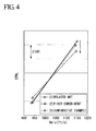
FIG. 4 is a graph which shows a relationship between speed and noise, and also shows a comparison between (1) noise of a related art jet engine, (2) noise of thejet engine 100 according to the present embodiment and (3) noise of thejet engine 200 of Comparative Example shown inFIG. 5 .
Comparative Example of (3) shown inFIG. 5 includesnotches 41 to 45 which are the same in number and configuration as those of thenotches notch 41 is located to correspond to the center line C of thebifurcation 13 andother notches 42 to 45 are distributed in the peripheral direction at substantially regular intervals. Accordingly, none of thenotches 41 to 45 exists inside the secondary vortex generation areas S1 and S2 in this example. - The graph in
FIG. 4 shows that noise (2) of the present embodiment is reduced by up to about 2dB as compared with noise (1) of the related art. Comparison of noise (3) of Comparative Example and noise (2) of the present embodiment shows that thenotches
It is also shown that there is no significant difference between Comparative Example (3) and related art (1), both of them have a small noise reduction effect and even have increased noise at the low-speed areas. - As described above, according to the present embodiment, noise generated by the
jet engine 100 is effectively reduced as compared with the related art by disposing thenotches bifurcation 13. - In the above-described embodiment, the notch 21 (22, 31, 32 and 33) is formed by folding the
downstream edge 12a of thetubular partition wall 12 in a peripheral direction inside as shown inFIG. 3 . In practice, however, the notch 31 (21, 22, 32 and 33) may alternatively protrude in a peripheral direction outside as shown inFIG. 6 .
Although fivenotches - Referring now to the drawings, a second embodiment of the invention will be described.
FIG. 7 is a cross-sectional view of ajet engine 300 according to the present embodiment seen from a downstream side, corresponding toFIG 2 according to the first embodiment. Components similar to those of the first embodiment will be denoted by similar reference numerals.
Abifurcation 13 of thejet engine 300 is provided to laterally protrude from an airplane body with its center line C being substantially horizontally oriented. Accordingly, thejet engine 300 is mounted on the airplane body while being cantilever-supported by thebifurcation 13. - As in the first embodiment, ridges of the
notches bifurcation 13 in the peripheral direction of the bypassflow discharge port 15.
Thenotch 31 is provided such that its ridge is displaced by about 90 degrees from the center line C of thebifurcation 13 in the peripheral direction of the bypassflow discharge port 15. Thenotch 32 is provided such that its ridge is displaced by about 225 degrees from the center line C of thebifurcation 13 in the peripheral direction of the bypassflow discharge port 15. Thenotch 33 is provided at a substantially intermediate position between thenotches
In the present embodiment, by disposing thenotches jet engine 300 when thejet engine 300 is horizontally divided into two parts. - In the thus-configured
jet engine 300, thenotches bifurcation 13 on the noise. The noise toward the ground may also be reduced by efficiently mixing the core flow Z with the bypass flow Y at the ground side of thejet engine 300. - Although the first and second projections are described as the
notches - As described above, the invention reduces jet engine noise by avoiding adverse effects of the presence of the bifurcation on an increase in noise.
Claims (10)
- A jet flow discharge nozzle, comprising:a tubular partition wall; a tubular casing which covers an outer periphery of the tubular partition wall; and a bifurcation which extends in an axial direction of the tubular partition wall and the casing so as to support downstream ends of the tubular partition wall and the casing from outside, inside the tubular partition wall being defined as a flow path for a high-speed core flow and a space between the tubular partition wall and the casing being defined as a flow path for a low-speed bypass flow,wherein a pair of first projections is provided at a downstream edge of the tubular partition wall near the bifurcation at positions symmetric about the bifurcation, each of the first projections being inclined to make an acute angle with the axial direction from an upstream side toward a downstream side.
- A jet flow discharge nozzle according to claim 1, wherein the first projections are provided inside secondary vortex generation areas located at both sides of the bifurcation.
- A jet flow discharge nozzle according to claim 1, wherein the first projections protrude toward a peripheral direction inside of the tubular partition wall.
- A jet flow discharge nozzle according to claim 1, further comprising a plurality of second projections disposed at intervals along a peripheral direction downstream edge of the tubular partition wall, each of the second projections being inclined to make an acute angle with the axial direction from an upstream side toward a downstream side and protruding toward peripheral direction inside and/or outside of the tubular partition wall.
- A jet flow discharge nozzle according to claim 1, wherein some of the second projections provided at a bifurcation side protrude toward the peripheral direction inside of the tubular partition wall.
- A jet flow discharge nozzle according to claim 1, wherein a number of the first and second projections which are located at a side of the bifurcation are greater than that of the first and second projections which are located at a side opposite to the bifurcation.
- A jet flow discharge nozzle according to claim 1, wherein the first projections are triangular pyramid-shaped bodies with one of their ridges facing the upstream side.
- A jet flow discharge nozzle according to claim 4, wherein the second projections are triangular pyramid-shaped bodies with one of their ridges facing the upstream side.
- A jet engine comprising: a fan which takes ambient air in; a compressor which compresses the intake ambient air; a combustion chamber which mixes fuel and the ambient air compressed by the compressor and then burn the mixture; and a turbine which drives the fan and the compressor by combustion gas from the combustion chamber,
wherein the jet engine further includes the jet flow discharge nozzle according to claim 1, the bifurcation is provided to protrude downward from an airplane wing and the jet engine is suspended and supported by the bifurcation. - A jet engine comprising: a fan which takes ambient air in; a compressor which compresses the intake ambient air; a combustion chamber which mixes fuel and the ambient air compressed by the compressor and then burn the mixture; and a turbine which drives the fan and the compressor by combustion gas from the combustion chamber,
wherein the jet engine further includes the jet flow discharge nozzle according to claim 1, the bifurcation is provided to laterally protrude from an airplane body and the jet engine is cantilever-supported by the bifurcation.
Applications Claiming Priority (2)
| Application Number | Priority Date | Filing Date | Title |
|---|---|---|---|
| JP2006340066A JP4830836B2 (en) | 2006-12-18 | 2006-12-18 | Jet jet exhaust nozzle and jet engine |
| PCT/JP2007/074295 WO2008075671A1 (en) | 2006-12-18 | 2007-12-18 | Jet flow discharge nozzle and jet engine |
Publications (3)
| Publication Number | Publication Date |
|---|---|
| EP2123894A1 true EP2123894A1 (en) | 2009-11-25 |
| EP2123894A4 EP2123894A4 (en) | 2011-03-16 |
| EP2123894B1 EP2123894B1 (en) | 2016-08-03 |
Family
ID=39536301
Family Applications (1)
| Application Number | Title | Priority Date | Filing Date |
|---|---|---|---|
| EP07850783.7A Active EP2123894B1 (en) | 2006-12-18 | 2007-12-18 | Jet flow discharge nozzle and corresponding jet engine |
Country Status (5)
| Country | Link |
|---|---|
| US (1) | US8418437B2 (en) |
| EP (1) | EP2123894B1 (en) |
| JP (1) | JP4830836B2 (en) |
| CA (1) | CA2673001C (en) |
| WO (1) | WO2008075671A1 (en) |
Cited By (2)
| Publication number | Priority date | Publication date | Assignee | Title |
|---|---|---|---|---|
| WO2010011381A1 (en) * | 2008-06-26 | 2010-01-28 | General Electric Company | Duplex tab exhaust nozzle |
| EP2557304A1 (en) * | 2010-04-09 | 2013-02-13 | IHI Corporation | Jet flow nozzle and jet engine |
Families Citing this family (14)
| Publication number | Priority date | Publication date | Assignee | Title |
|---|---|---|---|---|
| JP5322733B2 (en) * | 2009-03-31 | 2013-10-23 | Jx日鉱日石エネルギー株式会社 | Method for producing catalyst for selective oxidation reaction of carbon monoxide |
| JP5446749B2 (en) * | 2009-11-09 | 2014-03-19 | 株式会社Ihi | Engine exhaust nozzle and aircraft engine |
| JP5446783B2 (en) * | 2009-11-27 | 2014-03-19 | 株式会社Ihi | Engine exhaust nozzle and aircraft engine |
| JP5572060B2 (en) * | 2010-10-22 | 2014-08-13 | 株式会社やまびこ | Air blower |
| JP5821266B2 (en) * | 2011-04-28 | 2015-11-24 | 株式会社Ihi | Jet engine |
| US9783315B2 (en) * | 2012-02-24 | 2017-10-10 | Rohr, Inc. | Nacelle with longitudinal translating cowling and rotatable sleeves |
| FR2993921B1 (en) * | 2012-07-26 | 2014-07-18 | Snecma | METHOD FOR IMPROVING THE PERFORMANCE OF THE EJECTION SYSTEM OF A SEPARATE DOUBLE FLOW AIRCRAFT TURBOMOTOR, EJECTION SYSTEM AND CORRESPONDING TURBOMOTOR. |
| JP6035946B2 (en) | 2012-07-26 | 2016-11-30 | 株式会社Ihi | Engine duct and aircraft engine |
| DE102012219541A1 (en) * | 2012-10-25 | 2014-04-30 | Deutsches Zentrum für Luft- und Raumfahrt e.V. | Nozzle e.g. exhaust nozzle of aircraft jet engine, comprises a turbulence and/or swirl-generating structure which projects radially from the nozzle walls to the inside and/or on the outer side of the nozzle walls |
| JP6102648B2 (en) * | 2013-09-13 | 2017-03-29 | ソニー株式会社 | Information processing apparatus and information processing method |
| JP6437745B2 (en) * | 2014-06-20 | 2018-12-12 | 株式会社マキタ | nozzle |
| US10094332B2 (en) * | 2014-09-03 | 2018-10-09 | The Boeing Company | Core cowl for a turbofan engine |
| CN113226925A (en) * | 2018-11-09 | 2021-08-06 | 杰托普特拉股份有限公司 | Adaptive vertical take-off and landing propulsion system |
| WO2022140040A2 (en) * | 2020-12-03 | 2022-06-30 | The Government Of The United States Of America, As Represented By The Secretary Of The Navy | Methods and apparatuses for reducing engine noise |
Family Cites Families (13)
| Publication number | Priority date | Publication date | Assignee | Title |
|---|---|---|---|---|
| JPH04325397A (en) * | 1991-04-25 | 1992-11-13 | Mitsubishi Heavy Ind Ltd | Multi-engine airplane |
| US6360528B1 (en) * | 1997-10-31 | 2002-03-26 | General Electric Company | Chevron exhaust nozzle for a gas turbine engine |
| US6314721B1 (en) | 1998-09-04 | 2001-11-13 | United Technologies Corporation | Tabbed nozzle for jet noise suppression |
| US6532729B2 (en) * | 2001-05-31 | 2003-03-18 | General Electric Company | Shelf truncated chevron exhaust nozzle for reduction of exhaust noise and infrared (IR) signature |
| JP3962981B2 (en) * | 2001-12-07 | 2007-08-22 | 石川島播磨重工業株式会社 | Jet jet mixer |
| US6658839B2 (en) | 2002-02-28 | 2003-12-09 | The Boeing Company | Convergent/divergent segmented exhaust nozzle |
| FR2857416B1 (en) * | 2003-07-09 | 2007-05-25 | Snecma Moteurs | DEVICE FOR REDUCING JET NOISE OF A TURBOMACHINE |
| JP4325397B2 (en) | 2003-12-25 | 2009-09-02 | 株式会社豊田自動織機 | Tilt switch mounting structure |
| FR2873166B1 (en) * | 2004-07-13 | 2008-10-31 | Snecma Moteurs Sa | TURBOMACHINE TUBE WITH PATTERNS WITH JET NOISE REDUCTION |
| US7966824B2 (en) | 2006-08-09 | 2011-06-28 | The Boeing Company | Jet engine nozzle exit configurations and associated systems and methods |
| US8157207B2 (en) * | 2006-08-09 | 2012-04-17 | The Boeing Company | Jet engine nozzle exit configurations, including projections oriented relative to pylons, and associated systems and methods |
| US7520124B2 (en) * | 2006-09-12 | 2009-04-21 | United Technologies Corporation | Asymmetric serrated nozzle for exhaust noise reduction |
| US7963099B2 (en) * | 2007-05-21 | 2011-06-21 | General Electric Company | Fluted chevron exhaust nozzle |
-
2006
- 2006-12-18 JP JP2006340066A patent/JP4830836B2/en active Active
-
2007
- 2007-12-18 US US12/519,558 patent/US8418437B2/en active Active
- 2007-12-18 CA CA2673001A patent/CA2673001C/en active Active
- 2007-12-18 WO PCT/JP2007/074295 patent/WO2008075671A1/en active Application Filing
- 2007-12-18 EP EP07850783.7A patent/EP2123894B1/en active Active
Non-Patent Citations (2)
| Title |
|---|
| No further relevant documents disclosed * |
| See also references of WO2008075671A1 * |
Cited By (6)
| Publication number | Priority date | Publication date | Assignee | Title |
|---|---|---|---|---|
| WO2010011381A1 (en) * | 2008-06-26 | 2010-01-28 | General Electric Company | Duplex tab exhaust nozzle |
| GB2474377A (en) * | 2008-06-26 | 2011-04-13 | Gen Electric | Duplex tab exhaust nozzle |
| US8087250B2 (en) | 2008-06-26 | 2012-01-03 | General Electric Company | Duplex tab exhaust nozzle |
| GB2474377B (en) * | 2008-06-26 | 2012-02-29 | Gen Electric | Duplex tab exhaust nozzle |
| EP2557304A1 (en) * | 2010-04-09 | 2013-02-13 | IHI Corporation | Jet flow nozzle and jet engine |
| EP2557304A4 (en) * | 2010-04-09 | 2014-10-01 | Ihi Corp | Jet flow nozzle and jet engine |
Also Published As
| Publication number | Publication date |
|---|---|
| CA2673001C (en) | 2012-04-24 |
| WO2008075671A1 (en) | 2008-06-26 |
| EP2123894A4 (en) | 2011-03-16 |
| EP2123894B1 (en) | 2016-08-03 |
| JP2008151033A (en) | 2008-07-03 |
| US20100031628A1 (en) | 2010-02-11 |
| JP4830836B2 (en) | 2011-12-07 |
| US8418437B2 (en) | 2013-04-16 |
| CA2673001A1 (en) | 2008-06-26 |
Similar Documents
| Publication | Publication Date | Title |
|---|---|---|
| EP2123894B1 (en) | Jet flow discharge nozzle and corresponding jet engine | |
| US7434384B2 (en) | Fluid mixer with an integral fluid capture ducts forming auxiliary secondary chutes at the discharge end of said ducts | |
| JP5479021B2 (en) | Exhaust turbocharger compressor | |
| KR102056112B1 (en) | Compressors, Exhaust Gas Turbochargers and Internal Combustion Engines | |
| US20090155067A1 (en) | Nacelle assembly with turbulators | |
| EP2778380A2 (en) | Gas turbine engine exhaust mixer with aerodynamic struts | |
| EP1780124B1 (en) | Eductor swirl buster | |
| JP3956283B2 (en) | Jet jet lobe mixer | |
| EP2587037A2 (en) | Turbofan engine mixer assembly | |
| EP2980393B1 (en) | Gas turbine engine | |
| JP3962981B2 (en) | Jet jet mixer | |
| EP3779125A1 (en) | Gas turbine for aircraft | |
| US20190353054A1 (en) | Exhaust system for a gas turbine engine | |
| JP2015038324A (en) | Wing-like muffler substituted for oxidation catalyst | |
| US7937929B2 (en) | Exhaust duct with bypass channel | |
| EP3936710B1 (en) | Air intake for a stationary gas turbine engine | |
| JP2021038701A (en) | Exhaust passage | |
| US11105264B2 (en) | Asymmetric submerged air intake | |
| EP1835230A2 (en) | Supporting structure for spray bars | |
| KR20190079220A (en) | EGR valve with guide vane for turbulent flow reduction | |
| US11965653B2 (en) | Dilution air inlets with notched tip and slotted tail for combustor | |
| JPH08135503A (en) | Air-fuel mixing device for engine of aircraft | |
| JP2021050685A (en) | Exhaust structure | |
| JPH0893554A (en) | Jet engine |
Legal Events
| Date | Code | Title | Description |
|---|---|---|---|
| PUAI | Public reference made under article 153(3) epc to a published international application that has entered the european phase |
Free format text: ORIGINAL CODE: 0009012 |
|
| 17P | Request for examination filed |
Effective date: 20090706 |
|
| AK | Designated contracting states |
Kind code of ref document: A1 Designated state(s): AT BE BG CH CY CZ DE DK EE ES FI FR GB GR HU IE IS IT LI LT LU LV MC MT NL PL PT RO SE SI SK TR |
|
| DAX | Request for extension of the european patent (deleted) | ||
| REG | Reference to a national code |
Ref country code: DE Ref legal event code: R079 Ref document number: 602007047304 Country of ref document: DE Free format text: PREVIOUS MAIN CLASS: F02K0001480000 Ipc: B64D0029060000 |
|
| A4 | Supplementary search report drawn up and despatched |
Effective date: 20110211 |
|
| RIC1 | Information provided on ipc code assigned before grant |
Ipc: F02K 1/38 20060101ALI20110207BHEP Ipc: B64D 29/06 20060101AFI20110207BHEP |
|
| GRAP | Despatch of communication of intention to grant a patent |
Free format text: ORIGINAL CODE: EPIDOSNIGR1 |
|
| INTG | Intention to grant announced |
Effective date: 20160318 |
|
| GRAS | Grant fee paid |
Free format text: ORIGINAL CODE: EPIDOSNIGR3 |
|
| GRAA | (expected) grant |
Free format text: ORIGINAL CODE: 0009210 |
|
| AK | Designated contracting states |
Kind code of ref document: B1 Designated state(s): AT BE BG CH CY CZ DE DK EE ES FI FR GB GR HU IE IS IT LI LT LU LV MC MT NL PL PT RO SE SI SK TR |
|
| REG | Reference to a national code |
Ref country code: GB Ref legal event code: FG4D |
|
| REG | Reference to a national code |
Ref country code: CH Ref legal event code: EP Ref country code: AT Ref legal event code: REF Ref document number: 817152 Country of ref document: AT Kind code of ref document: T Effective date: 20160815 |
|
| REG | Reference to a national code |
Ref country code: IE Ref legal event code: FG4D |
|
| REG | Reference to a national code |
Ref country code: DE Ref legal event code: R096 Ref document number: 602007047304 Country of ref document: DE |
|
| REG | Reference to a national code |
Ref country code: FR Ref legal event code: PLFP Year of fee payment: 10 |
|
| REG | Reference to a national code |
Ref country code: NL Ref legal event code: MP Effective date: 20160803 |
|
| REG | Reference to a national code |
Ref country code: LT Ref legal event code: MG4D |
|
| REG | Reference to a national code |
Ref country code: AT Ref legal event code: MK05 Ref document number: 817152 Country of ref document: AT Kind code of ref document: T Effective date: 20160803 |
|
| PG25 | Lapsed in a contracting state [announced via postgrant information from national office to epo] |
Ref country code: FI Free format text: LAPSE BECAUSE OF FAILURE TO SUBMIT A TRANSLATION OF THE DESCRIPTION OR TO PAY THE FEE WITHIN THE PRESCRIBED TIME-LIMIT Effective date: 20160803 Ref country code: LT Free format text: LAPSE BECAUSE OF FAILURE TO SUBMIT A TRANSLATION OF THE DESCRIPTION OR TO PAY THE FEE WITHIN THE PRESCRIBED TIME-LIMIT Effective date: 20160803 Ref country code: NL Free format text: LAPSE BECAUSE OF FAILURE TO SUBMIT A TRANSLATION OF THE DESCRIPTION OR TO PAY THE FEE WITHIN THE PRESCRIBED TIME-LIMIT Effective date: 20160803 Ref country code: IS Free format text: LAPSE BECAUSE OF FAILURE TO SUBMIT A TRANSLATION OF THE DESCRIPTION OR TO PAY THE FEE WITHIN THE PRESCRIBED TIME-LIMIT Effective date: 20161203 |
|
| PG25 | Lapsed in a contracting state [announced via postgrant information from national office to epo] |
Ref country code: AT Free format text: LAPSE BECAUSE OF FAILURE TO SUBMIT A TRANSLATION OF THE DESCRIPTION OR TO PAY THE FEE WITHIN THE PRESCRIBED TIME-LIMIT Effective date: 20160803 Ref country code: ES Free format text: LAPSE BECAUSE OF FAILURE TO SUBMIT A TRANSLATION OF THE DESCRIPTION OR TO PAY THE FEE WITHIN THE PRESCRIBED TIME-LIMIT Effective date: 20160803 Ref country code: PT Free format text: LAPSE BECAUSE OF FAILURE TO SUBMIT A TRANSLATION OF THE DESCRIPTION OR TO PAY THE FEE WITHIN THE PRESCRIBED TIME-LIMIT Effective date: 20161205 Ref country code: GR Free format text: LAPSE BECAUSE OF FAILURE TO SUBMIT A TRANSLATION OF THE DESCRIPTION OR TO PAY THE FEE WITHIN THE PRESCRIBED TIME-LIMIT Effective date: 20161104 Ref country code: PL Free format text: LAPSE BECAUSE OF FAILURE TO SUBMIT A TRANSLATION OF THE DESCRIPTION OR TO PAY THE FEE WITHIN THE PRESCRIBED TIME-LIMIT Effective date: 20160803 Ref country code: LV Free format text: LAPSE BECAUSE OF FAILURE TO SUBMIT A TRANSLATION OF THE DESCRIPTION OR TO PAY THE FEE WITHIN THE PRESCRIBED TIME-LIMIT Effective date: 20160803 Ref country code: SE Free format text: LAPSE BECAUSE OF FAILURE TO SUBMIT A TRANSLATION OF THE DESCRIPTION OR TO PAY THE FEE WITHIN THE PRESCRIBED TIME-LIMIT Effective date: 20160803 |
|
| PG25 | Lapsed in a contracting state [announced via postgrant information from national office to epo] |
Ref country code: RO Free format text: LAPSE BECAUSE OF FAILURE TO SUBMIT A TRANSLATION OF THE DESCRIPTION OR TO PAY THE FEE WITHIN THE PRESCRIBED TIME-LIMIT Effective date: 20160803 Ref country code: EE Free format text: LAPSE BECAUSE OF FAILURE TO SUBMIT A TRANSLATION OF THE DESCRIPTION OR TO PAY THE FEE WITHIN THE PRESCRIBED TIME-LIMIT Effective date: 20160803 |
|
| REG | Reference to a national code |
Ref country code: DE Ref legal event code: R097 Ref document number: 602007047304 Country of ref document: DE |
|
| PG25 | Lapsed in a contracting state [announced via postgrant information from national office to epo] |
Ref country code: BE Free format text: LAPSE BECAUSE OF FAILURE TO SUBMIT A TRANSLATION OF THE DESCRIPTION OR TO PAY THE FEE WITHIN THE PRESCRIBED TIME-LIMIT Effective date: 20160803 Ref country code: DK Free format text: LAPSE BECAUSE OF FAILURE TO SUBMIT A TRANSLATION OF THE DESCRIPTION OR TO PAY THE FEE WITHIN THE PRESCRIBED TIME-LIMIT Effective date: 20160803 Ref country code: BG Free format text: LAPSE BECAUSE OF FAILURE TO SUBMIT A TRANSLATION OF THE DESCRIPTION OR TO PAY THE FEE WITHIN THE PRESCRIBED TIME-LIMIT Effective date: 20161103 Ref country code: CZ Free format text: LAPSE BECAUSE OF FAILURE TO SUBMIT A TRANSLATION OF THE DESCRIPTION OR TO PAY THE FEE WITHIN THE PRESCRIBED TIME-LIMIT Effective date: 20160803 Ref country code: SK Free format text: LAPSE BECAUSE OF FAILURE TO SUBMIT A TRANSLATION OF THE DESCRIPTION OR TO PAY THE FEE WITHIN THE PRESCRIBED TIME-LIMIT Effective date: 20160803 |
|
| PLBE | No opposition filed within time limit |
Free format text: ORIGINAL CODE: 0009261 |
|
| STAA | Information on the status of an ep patent application or granted ep patent |
Free format text: STATUS: NO OPPOSITION FILED WITHIN TIME LIMIT |
|
| 26N | No opposition filed |
Effective date: 20170504 |
|
| REG | Reference to a national code |
Ref country code: CH Ref legal event code: PL |
|
| PG25 | Lapsed in a contracting state [announced via postgrant information from national office to epo] |
Ref country code: SI Free format text: LAPSE BECAUSE OF FAILURE TO SUBMIT A TRANSLATION OF THE DESCRIPTION OR TO PAY THE FEE WITHIN THE PRESCRIBED TIME-LIMIT Effective date: 20160803 |
|
| PG25 | Lapsed in a contracting state [announced via postgrant information from national office to epo] |
Ref country code: MC Free format text: LAPSE BECAUSE OF FAILURE TO SUBMIT A TRANSLATION OF THE DESCRIPTION OR TO PAY THE FEE WITHIN THE PRESCRIBED TIME-LIMIT Effective date: 20160803 |
|
| REG | Reference to a national code |
Ref country code: IE Ref legal event code: MM4A |
|
| PG25 | Lapsed in a contracting state [announced via postgrant information from national office to epo] |
Ref country code: LI Free format text: LAPSE BECAUSE OF NON-PAYMENT OF DUE FEES Effective date: 20161231 Ref country code: CH Free format text: LAPSE BECAUSE OF NON-PAYMENT OF DUE FEES Effective date: 20161231 Ref country code: LU Free format text: LAPSE BECAUSE OF NON-PAYMENT OF DUE FEES Effective date: 20161218 |
|
| REG | Reference to a national code |
Ref country code: FR Ref legal event code: PLFP Year of fee payment: 11 |
|
| PG25 | Lapsed in a contracting state [announced via postgrant information from national office to epo] |
Ref country code: IE Free format text: LAPSE BECAUSE OF NON-PAYMENT OF DUE FEES Effective date: 20161218 |
|
| PG25 | Lapsed in a contracting state [announced via postgrant information from national office to epo] |
Ref country code: CY Free format text: LAPSE BECAUSE OF FAILURE TO SUBMIT A TRANSLATION OF THE DESCRIPTION OR TO PAY THE FEE WITHIN THE PRESCRIBED TIME-LIMIT Effective date: 20160803 Ref country code: HU Free format text: LAPSE BECAUSE OF FAILURE TO SUBMIT A TRANSLATION OF THE DESCRIPTION OR TO PAY THE FEE WITHIN THE PRESCRIBED TIME-LIMIT; INVALID AB INITIO Effective date: 20071218 |
|
| PG25 | Lapsed in a contracting state [announced via postgrant information from national office to epo] |
Ref country code: TR Free format text: LAPSE BECAUSE OF FAILURE TO SUBMIT A TRANSLATION OF THE DESCRIPTION OR TO PAY THE FEE WITHIN THE PRESCRIBED TIME-LIMIT Effective date: 20160803 |
|
| PG25 | Lapsed in a contracting state [announced via postgrant information from national office to epo] |
Ref country code: MT Free format text: LAPSE BECAUSE OF NON-PAYMENT OF DUE FEES Effective date: 20161218 |
|
| PGFP | Annual fee paid to national office [announced via postgrant information from national office to epo] |
Ref country code: IT Payment date: 20221111 Year of fee payment: 16 Ref country code: FR Payment date: 20221110 Year of fee payment: 16 Ref country code: DE Payment date: 20221102 Year of fee payment: 16 |
|
| PGFP | Annual fee paid to national office [announced via postgrant information from national office to epo] |
Ref country code: GB Payment date: 20231102 Year of fee payment: 17 |