EP2123879A1 - Deflector for mixing and homogenisize exhaust flow in front of an exhaust gas converter - Google Patents
Deflector for mixing and homogenisize exhaust flow in front of an exhaust gas converter Download PDFInfo
- Publication number
- EP2123879A1 EP2123879A1 EP08156431A EP08156431A EP2123879A1 EP 2123879 A1 EP2123879 A1 EP 2123879A1 EP 08156431 A EP08156431 A EP 08156431A EP 08156431 A EP08156431 A EP 08156431A EP 2123879 A1 EP2123879 A1 EP 2123879A1
- Authority
- EP
- European Patent Office
- Prior art keywords
- inlet pipe
- hole
- deflector
- manufacturing process
- elongated member
- Prior art date
- Legal status (The legal status is an assumption and is not a legal conclusion. Google has not performed a legal analysis and makes no representation as to the accuracy of the status listed.)
- Withdrawn
Links
Images

Classifications
-
- B—PERFORMING OPERATIONS; TRANSPORTING
- B01—PHYSICAL OR CHEMICAL PROCESSES OR APPARATUS IN GENERAL
- B01F—MIXING, e.g. DISSOLVING, EMULSIFYING OR DISPERSING
- B01F25/00—Flow mixers; Mixers for falling materials, e.g. solid particles
- B01F25/40—Static mixers
- B01F25/42—Static mixers in which the mixing is affected by moving the components jointly in changing directions, e.g. in tubes provided with baffles or obstructions
- B01F25/43—Mixing tubes, e.g. wherein the material is moved in a radial or partly reversed direction
- B01F25/431—Straight mixing tubes with baffles or obstructions that do not cause substantial pressure drop; Baffles therefor
- B01F25/43197—Straight mixing tubes with baffles or obstructions that do not cause substantial pressure drop; Baffles therefor characterised by the mounting of the baffles or obstructions
- B01F25/431971—Mounted on the wall
-
- F—MECHANICAL ENGINEERING; LIGHTING; HEATING; WEAPONS; BLASTING
- F01—MACHINES OR ENGINES IN GENERAL; ENGINE PLANTS IN GENERAL; STEAM ENGINES
- F01N—GAS-FLOW SILENCERS OR EXHAUST APPARATUS FOR MACHINES OR ENGINES IN GENERAL; GAS-FLOW SILENCERS OR EXHAUST APPARATUS FOR INTERNAL-COMBUSTION ENGINES
- F01N3/00—Exhaust or silencing apparatus having means for purifying, rendering innocuous, or otherwise treating exhaust
- F01N3/08—Exhaust or silencing apparatus having means for purifying, rendering innocuous, or otherwise treating exhaust for rendering innocuous
- F01N3/10—Exhaust or silencing apparatus having means for purifying, rendering innocuous, or otherwise treating exhaust for rendering innocuous by thermal or catalytic conversion of noxious components of exhaust
- F01N3/24—Exhaust or silencing apparatus having means for purifying, rendering innocuous, or otherwise treating exhaust for rendering innocuous by thermal or catalytic conversion of noxious components of exhaust characterised by constructional aspects of converting apparatus
- F01N3/28—Construction of catalytic reactors
- F01N3/2892—Exhaust flow directors or the like, e.g. upstream of catalytic device
-
- B—PERFORMING OPERATIONS; TRANSPORTING
- B01—PHYSICAL OR CHEMICAL PROCESSES OR APPARATUS IN GENERAL
- B01F—MIXING, e.g. DISSOLVING, EMULSIFYING OR DISPERSING
- B01F25/00—Flow mixers; Mixers for falling materials, e.g. solid particles
- B01F25/40—Static mixers
- B01F25/42—Static mixers in which the mixing is affected by moving the components jointly in changing directions, e.g. in tubes provided with baffles or obstructions
- B01F25/43—Mixing tubes, e.g. wherein the material is moved in a radial or partly reversed direction
- B01F25/431—Straight mixing tubes with baffles or obstructions that do not cause substantial pressure drop; Baffles therefor
-
- B—PERFORMING OPERATIONS; TRANSPORTING
- B01—PHYSICAL OR CHEMICAL PROCESSES OR APPARATUS IN GENERAL
- B01F—MIXING, e.g. DISSOLVING, EMULSIFYING OR DISPERSING
- B01F25/00—Flow mixers; Mixers for falling materials, e.g. solid particles
- B01F25/40—Static mixers
- B01F25/42—Static mixers in which the mixing is affected by moving the components jointly in changing directions, e.g. in tubes provided with baffles or obstructions
- B01F25/43—Mixing tubes, e.g. wherein the material is moved in a radial or partly reversed direction
- B01F25/431—Straight mixing tubes with baffles or obstructions that do not cause substantial pressure drop; Baffles therefor
- B01F25/4319—Tubular elements
-
- F—MECHANICAL ENGINEERING; LIGHTING; HEATING; WEAPONS; BLASTING
- F01—MACHINES OR ENGINES IN GENERAL; ENGINE PLANTS IN GENERAL; STEAM ENGINES
- F01N—GAS-FLOW SILENCERS OR EXHAUST APPARATUS FOR MACHINES OR ENGINES IN GENERAL; GAS-FLOW SILENCERS OR EXHAUST APPARATUS FOR INTERNAL-COMBUSTION ENGINES
- F01N2240/00—Combination or association of two or more different exhaust treating devices, or of at least one such device with an auxiliary device, not covered by indexing codes F01N2230/00 or F01N2250/00, one of the devices being
- F01N2240/20—Combination or association of two or more different exhaust treating devices, or of at least one such device with an auxiliary device, not covered by indexing codes F01N2230/00 or F01N2250/00, one of the devices being a flow director or deflector
-
- Y—GENERAL TAGGING OF NEW TECHNOLOGICAL DEVELOPMENTS; GENERAL TAGGING OF CROSS-SECTIONAL TECHNOLOGIES SPANNING OVER SEVERAL SECTIONS OF THE IPC; TECHNICAL SUBJECTS COVERED BY FORMER USPC CROSS-REFERENCE ART COLLECTIONS [XRACs] AND DIGESTS
- Y02—TECHNOLOGIES OR APPLICATIONS FOR MITIGATION OR ADAPTATION AGAINST CLIMATE CHANGE
- Y02A—TECHNOLOGIES FOR ADAPTATION TO CLIMATE CHANGE
- Y02A50/00—TECHNOLOGIES FOR ADAPTATION TO CLIMATE CHANGE in human health protection, e.g. against extreme weather
- Y02A50/20—Air quality improvement or preservation, e.g. vehicle emission control or emission reduction by using catalytic converters
Definitions
- the present invention is in the domain of motor vehicle exhaust systems.
- a motor vehicle exhaust line generally comprises a collector, an inlet pipe, an exhaust gas converter and an outlet pipe connected in series so that the exhaust gas coming out of an internal combustion engine of a vehicle flows through these elements prior to being released outside.
- a deflector can be installed in the inlet pipe upstream the exhaust gas converter and substantially transversal to the gas flow.
- the deflector creates turbulences in the gas flow.
- the turbulences improve the homogenization of the exhaust gas prior to entering in the exhaust gas converter.
- the homogenization of the gas flow improves the efficiency of the exhaust gas converter and reduces the atmospheric pollution.
- the deflector has become an important feature of the exhaust system and numerous vehicles are equipped with a deflector.
- the deflector is made of a tubular portion including deflection means and interconnected between two portions of the inlet pipe.
- the deflection means can take multiple shapes such as a perforated disc, a four leg cross, a multibranch star...
- the present invention proposes a simple process of manufacturing an exhaust line equipped with a deflector. Additionally, the process can be executed to install a deflector in an exhaust line which has not been designed originally for receiving a deflector.
- the object of the present invention is a manufacturing process to install a deflector in a motor vehicle exhaust line, the exhaust line comprising a collector an inlet pipe an exhaust converter and an outlet pipe, all connected in series so that the exhaust gas flows through these elements prior of being released outside.
- the inlet pipe further comprises a wall and the manufacturing process object of this invention consists in piercing the wall, sliding an elongated member through the hole and fixing the elongated member to the inlet pipe so that the elongated member constitutes a deflector for generating turbulences in the gas flow upstream with regards to the exhaust gas converter.
- the deflector can be installed before or after connection of the inlet pipe to the exhaust gas converter.
- the deflector can be located in the near vicinity of the entry of converter. It can as well be located at a further upstream distance from the entry of the converter.
- FIG. 1 is a schematic view of an exhaust line 1 illustrating the overall construction according to a first embodiment of the present invention.
- the exhaust line 1 comprises an inlet pipe 2, a gas converter 4, such as a catalytic converter, and an outlet pipe 6.
- the inlet pipe 2 is connected to the converter 4 so that the exhaust gas 8 flows through the inlet pipe 2 and enter into the converter 4.
- On its exit side the converter 4 is connected to the outlet pipe 6.
- the exhaust gas flow 8 travels through the inlet pipe 2 then through the converter 4 and is finally released outside as flow 9.
- a deflector 10 is installed in the inlet pipe 2 upstream the converter 4.
- the deflector 10 comprises an elongated member 12 positioned in the inlet pipe 2, transversally to the gas flow 8.
- the inlet pipe 2 comprises more than one deflector, one in the near vicinity 20 of the exhaust gas converter 4 and an other one at a more distant location 22.
- Figure 2 and Figure 3 are detailed views of the area of the inlet pipe 2 where the deflector 10 is, independently of the location 20 or 22 in the inlet pipe 2.
- the inlet pipe 2 is provided with two opposite holes 14, 16 through which the elongated member 12 is inserted.
- the deflector 10 is constituted of two elongated members located in the same transversal plan in the inlet pipe 2.
- the inlet pipe 2 is provided with two pairs of opposite through holes, 14 and 16, and, 23 and 24.
- the axes between holes 14 and 16 and between holes 23 and 24 are angularly shifted substantially by 90°.
- a first elongated member 12 is provided with an intermediate transversal opening 21.
- the elongated member 12 is inserted through the holes 14 and 16.
- a second member 13 is inserted through holes 23 and 24 and extends through said opening 21.
- the elongated member 12 can be fixed by one extremity only.
- the inlet pipe 2 is then provided with one hole 14 through which the elongated member 12 is slided. Therefore the elongated member 12 extends only through said hole by one extremity 17 which is fixed (e.g. welded) to the wall 21 of the inlet pipe 2.
- the elongated member is a cylinder with circular section. It could also be made of a rod with rectangular section or it could have other type of cross-section.
- the deflector 10 can be installed in the inlet pipe 2 before or after connecting the inlet pipe 2 to the exhaust gas converter 4.
- the elongated member 12 has a greater length than the cross-section of the inlet pipe 2 to make the attachment to the outside surface of the cylindrical wall 21 easier.
- the elongated member 12 is inserted through the holes 14 and 16, as illustrated by Figure 4 , so that each transversal end 17, 19 extend outside the wall 21 of the inlet pipe 2.
- the elongated member 12 is attached to the cylindrical wall 21 of the inlet pipe 2, for example by welding.
- the elongated members 12 and 13 have greater lengths then the cross-section of the inlet pipe 2 to make the attachment to the outside surface of the cylindrical wall 21 easier.
- the elongated member 12 is inserted through the holes 14 and 16 so that each transversal end 17, 19 extend outside the wall 21 of the inlet pipe 2.
- the elongated member 12 is oriented so that the transversal opening 21 is made substantially coaxial with the axis line joining holes 23 and 24.
- the elongated member 13 is inserted through holes 23 and 24, passing through the opening 21 of the elongated member 12.
- the elongated members 12 and 13 are attached to the cylindrical wall 21 of the inlet pipe 2, for example by welding.
- the man of the art will chose the most appropriate fixing method for the elongated member 12 to the inlet pipe 2. Welding, brazing, gluing, screwing... are compatible with the present invention.
- the process described enables to install the deflector 10 without requirement of additional specific volume in the exhaust line 1.
Landscapes
- Chemical & Material Sciences (AREA)
- Chemical Kinetics & Catalysis (AREA)
- Dispersion Chemistry (AREA)
- Engineering & Computer Science (AREA)
- Health & Medical Sciences (AREA)
- Toxicology (AREA)
- Combustion & Propulsion (AREA)
- Mechanical Engineering (AREA)
- General Engineering & Computer Science (AREA)
- Exhaust Silencers (AREA)
Abstract
A manufacturing process to add a deflector (10,22) in a motor vehicle exhausts line comprising a collector, an inlet pipe (2), an exhaust converter (4) and an outlet pipe (6) connected in series; the inlet pipe further comprising a wall; the deflector (10,22), located upstream the exhaust converter (4) and "more or less" transversal to the gas flow, creates turbulence's in the gas flow, "improving" the homogenization of the exhaust gases prior to enter in the exhaust converter (4); the deflector (10,22) comprising an elongated member (12); the manufacturing process is characterized in that it comprises the following steps:
- piercing the inlet pipe (2) with one hole of similar dimension to the member's cross section;
- inserting the member (12) from the outside of the inlet pipe, through the hole;
- fixing the member to the inlet pipe.
- piercing the inlet pipe (2) with one hole of similar dimension to the member's cross section;
- inserting the member (12) from the outside of the inlet pipe, through the hole;
- fixing the member to the inlet pipe.
Description
- The present invention is in the domain of motor vehicle exhaust systems.
- A motor vehicle exhaust line generally comprises a collector, an inlet pipe, an exhaust gas converter and an outlet pipe connected in series so that the exhaust gas coming out of an internal combustion engine of a vehicle flows through these elements prior to being released outside. To improve the efficiency of the exhaust gas converter a deflector can be installed in the inlet pipe upstream the exhaust gas converter and substantially transversal to the gas flow. The deflector creates turbulences in the gas flow. The turbulences improve the homogenization of the exhaust gas prior to entering in the exhaust gas converter. The homogenization of the gas flow improves the efficiency of the exhaust gas converter and reduces the atmospheric pollution. The deflector has become an important feature of the exhaust system and numerous vehicles are equipped with a deflector.
- Generally the deflector is made of a tubular portion including deflection means and interconnected between two portions of the inlet pipe. The deflection means can take multiple shapes such as a perforated disc, a four leg cross, a multibranch star...
- Such a deflector is complex, difficult to assemble and therefore costly.
The present invention proposes a simple process of manufacturing an exhaust line equipped with a deflector. Additionally, the process can be executed to install a deflector in an exhaust line which has not been designed originally for receiving a deflector. - The object of the present invention is a manufacturing process to install a deflector in a motor vehicle exhaust line, the exhaust line comprising a collector an inlet pipe an exhaust converter and an outlet pipe, all connected in series so that the exhaust gas flows through these elements prior of being released outside. The inlet pipe further comprises a wall and the manufacturing process object of this invention consists in piercing the wall, sliding an elongated member through the hole and fixing the elongated member to the inlet pipe so that the elongated member constitutes a deflector for generating turbulences in the gas flow upstream with regards to the exhaust gas converter.
- The deflector can be installed before or after connection of the inlet pipe to the exhaust gas converter.
- The generic process here described can be easily adapted to several variants depending on the homogenization efficiency required for the gas flow:
- Should the efficiency not be optimum with one elongated member, additional members, angularly or/and axially shifted relatively to the first member, can be added following a similar process.
- The deflector can be located in the near vicinity of the entry of converter. It can as well be located at a further upstream distance from the entry of the converter.
- Other advantages of the present invention will be readily appreciated by reference to the following detailed description when considered in connection with the accompanying drawings wherein:
-
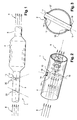
Figure 1 is a schematic view of an exhaust line comprising a deflector manufactured according to the method of the invention; -
Figure 2 is a detailed view showing an inlet pipe portion wherein the deflector is located; -
Figure 3 is a transversal cross-section view showing the deflector after assembly in the inlet pipe; -
Figure 4 illustrates a step of the process of installation of the elongated member in the inlet pipe; -
Figure 5 is a detailed view showing an inlet pipe portion wherein the deflector comprising two orthogonal members is located. -
Figure 1 is a schematic view of anexhaust line 1 illustrating the overall construction according to a first embodiment of the present invention. Theexhaust line 1 comprises aninlet pipe 2, agas converter 4, such as a catalytic converter, and anoutlet pipe 6. Theinlet pipe 2 is connected to theconverter 4 so that theexhaust gas 8 flows through theinlet pipe 2 and enter into theconverter 4. On its exit side theconverter 4 is connected to theoutlet pipe 6. Theexhaust gas flow 8 travels through theinlet pipe 2 then through theconverter 4 and is finally released outside asflow 9. Adeflector 10 is installed in theinlet pipe 2 upstream theconverter 4. Thedeflector 10 comprises anelongated member 12 positioned in theinlet pipe 2, transversally to thegas flow 8. - In a first embodiment of the present invention the
inlet pipe 2 comprises more than one deflector, one in thenear vicinity 20 of theexhaust gas converter 4 and an other one at a moredistant location 22. - The man of the art will understand that the deflectors illustrated in
Figure 1 can have their axis shifted at any desired angle. -
Figure 2 and Figure 3 are detailed views of the area of theinlet pipe 2 where thedeflector 10 is, independently of thelocation inlet pipe 2. Theinlet pipe 2 is provided with twoopposite holes elongated member 12 is inserted. - According to a second embodiment shown on
Figure 5 thedeflector 10 is constituted of two elongated members located in the same transversal plan in theinlet pipe 2. Theinlet pipe 2 is provided with two pairs of opposite through holes, 14 and 16, and, 23 and 24. The axes betweenholes holes elongated member 12 is provided with an intermediatetransversal opening 21. Theelongated member 12 is inserted through theholes second member 13 is inserted throughholes - Alternative embodiments and complementary information can easily be understood without pictures. For example, the
elongated member 12 can be fixed by one extremity only. Theinlet pipe 2 is then provided with onehole 14 through which theelongated member 12 is slided. Therefore theelongated member 12 extends only through said hole by oneextremity 17 which is fixed (e.g. welded) to thewall 21 of theinlet pipe 2. - Here the elongated member is a cylinder with circular section. It could also be made of a rod with rectangular section or it could have other type of cross-section.
- The process, by which the
deflector 10 is being installed in theinlet pipe 2, will now be described. - Advantageously, following the process here after described, the
deflector 10 can be installed in theinlet pipe 2 before or after connecting theinlet pipe 2 to theexhaust gas converter 4. - The process by which the
deflector 10 is being installed in theinlet pipe 2, according to the first embodiment of the present invention will now be described. - Advantageously, the
elongated member 12 has a greater length than the cross-section of theinlet pipe 2 to make the attachment to the outside surface of thecylindrical wall 21 easier. Theelongated member 12 is inserted through theholes Figure 4 , so that eachtransversal end wall 21 of theinlet pipe 2. Theelongated member 12 is attached to thecylindrical wall 21 of theinlet pipe 2, for example by welding. - The process by which the
deflector 10 is being installed in theinlet pipe 2, according to the second embodiment of the present invention will now be described. - The
elongated members inlet pipe 2 to make the attachment to the outside surface of thecylindrical wall 21 easier. Similarly to the process described for the first embodiment, theelongated member 12 is inserted through theholes transversal end wall 21 of theinlet pipe 2. Then theelongated member 12 is oriented so that thetransversal opening 21 is made substantially coaxial with the axisline joining holes elongated member 13 is inserted throughholes elongated member 12. Theelongated members cylindrical wall 21 of theinlet pipe 2, for example by welding. - The man of the art will chose the most appropriate fixing method for the
elongated member 12 to theinlet pipe 2. Welding, brazing, gluing, screwing... are compatible with the present invention. - Advantageously, the process described enables to install the
deflector 10 without requirement of additional specific volume in theexhaust line 1.
Claims (8)
- A manufacturing process for providing an exhaust line (1) of an internal combustion engine with a deflector (10), said exhaust line (1) comprising an inlet pipe (2), an exhaust gas converter (4), and an outlet pipe (6) connected in series so that exhaust gas (8) coming out of the internal combustion engine flow through the exhaust line (1) prior to being released outside, said manufacturing process being characterized in that it comprises the following steps:- piercing at least a first hole in the inlet pipe,- inserting at least a first elongated member through said first hole into the inlet pipe,- fixing said first elongated member to the inlet pipe, so that said first elongated member constitutes a deflector (10) for generating turbulences (9) in the gas flow upstream with regards to the exhaust gas converter (4).
- The manufacturing process as set forth in claim 1, characterized in that it further comprises the steps of:- piercing at least a second hole in the inlet pipe, said second hole being shifted along the inlet pipe direction with regards to said first hole,- inserting at least a second elongated member through said second hole into the inlet pipe,- fixing said second elongated member to the inlet pipe.
- The manufacturing process as set forth in claim 2, characterized in that said second hole is angularly shifted along the inlet pipe axis with regards to said first hole so that the two elongated members extend in non-parallel directions.
- The manufacturing process as set forth in claim 3, characterized in that said second hole is located in the same transversal plane as said first hole so that the two elongated members cross over inside the inlet pipe.
- The manufacturing process as set forth in anyone of claims 1 to 4, characterized in that it further comprises the steps of:- piercing at least one opposite hole in the inlet pipe, said opposite hole being located diametrically opposite to said first or second hole with regards to the inlet pipe axis,- inserting the corresponding elongated member both through said first or second hole and through said opposite hole.
- The manufacturing process as set forth in anyone of claims 1 to 5, characterized in that said fixing step comprises a brazing step.
- The manufacturing process as set forth in anyone of claims 1 to 6, characterized in that the elongated member is made of a rod.
- The manufacturing process as set forth in anyone of the claims 1 to 7, characterized in that the deflector is installed in the inlet pipe after the connection of the inlet pipe to the exhaust gas converter.
Priority Applications (1)
| Application Number | Priority Date | Filing Date | Title |
|---|---|---|---|
| EP08156431A EP2123879A1 (en) | 2008-05-19 | 2008-05-19 | Deflector for mixing and homogenisize exhaust flow in front of an exhaust gas converter |
Applications Claiming Priority (1)
| Application Number | Priority Date | Filing Date | Title |
|---|---|---|---|
| EP08156431A EP2123879A1 (en) | 2008-05-19 | 2008-05-19 | Deflector for mixing and homogenisize exhaust flow in front of an exhaust gas converter |
Publications (1)
| Publication Number | Publication Date |
|---|---|
| EP2123879A1 true EP2123879A1 (en) | 2009-11-25 |
Family
ID=39998941
Family Applications (1)
| Application Number | Title | Priority Date | Filing Date |
|---|---|---|---|
| EP08156431A Withdrawn EP2123879A1 (en) | 2008-05-19 | 2008-05-19 | Deflector for mixing and homogenisize exhaust flow in front of an exhaust gas converter |
Country Status (1)
| Country | Link |
|---|---|
| EP (1) | EP2123879A1 (en) |
Cited By (2)
| Publication number | Priority date | Publication date | Assignee | Title |
|---|---|---|---|---|
| JP2012077615A (en) * | 2010-09-30 | 2012-04-19 | Daihatsu Motor Co Ltd | Exhaust device in internal combustion engine |
| CN110735701A (en) * | 2019-11-12 | 2020-01-31 | 无锡威孚力达催化净化器有限责任公司 | multi-petal converging type soot cyclone mixing partition plate and exhaust aftertreatment device |
Citations (6)
| Publication number | Priority date | Publication date | Assignee | Title |
|---|---|---|---|---|
| DE2036597A1 (en) * | 1970-07-23 | 1972-01-27 | Yokogawa Electric Works Ltd | Flowmeter |
| EP0638732A1 (en) * | 1993-08-03 | 1995-02-15 | BDAG Balcke-Dürr Aktiengesellschaft | Diffuser |
| US5941069A (en) * | 1993-10-22 | 1999-08-24 | Madison Combustion Associates | Exhaust apparatus |
| US5992141A (en) * | 1996-04-02 | 1999-11-30 | Kleen Air Systems, Inc. | Ammonia injection in NOx control |
| WO2003048537A1 (en) * | 2001-11-28 | 2003-06-12 | Robert Bosch Gmbh | Method for operating an internal combustion engine and internal combustion engine |
| EP1956206A2 (en) * | 2007-02-09 | 2008-08-13 | Sulzer Chemtech AG | Exhaust gas cleaning system |
-
2008
- 2008-05-19 EP EP08156431A patent/EP2123879A1/en not_active Withdrawn
Patent Citations (6)
| Publication number | Priority date | Publication date | Assignee | Title |
|---|---|---|---|---|
| DE2036597A1 (en) * | 1970-07-23 | 1972-01-27 | Yokogawa Electric Works Ltd | Flowmeter |
| EP0638732A1 (en) * | 1993-08-03 | 1995-02-15 | BDAG Balcke-Dürr Aktiengesellschaft | Diffuser |
| US5941069A (en) * | 1993-10-22 | 1999-08-24 | Madison Combustion Associates | Exhaust apparatus |
| US5992141A (en) * | 1996-04-02 | 1999-11-30 | Kleen Air Systems, Inc. | Ammonia injection in NOx control |
| WO2003048537A1 (en) * | 2001-11-28 | 2003-06-12 | Robert Bosch Gmbh | Method for operating an internal combustion engine and internal combustion engine |
| EP1956206A2 (en) * | 2007-02-09 | 2008-08-13 | Sulzer Chemtech AG | Exhaust gas cleaning system |
Cited By (3)
| Publication number | Priority date | Publication date | Assignee | Title |
|---|---|---|---|---|
| JP2012077615A (en) * | 2010-09-30 | 2012-04-19 | Daihatsu Motor Co Ltd | Exhaust device in internal combustion engine |
| CN110735701A (en) * | 2019-11-12 | 2020-01-31 | 无锡威孚力达催化净化器有限责任公司 | multi-petal converging type soot cyclone mixing partition plate and exhaust aftertreatment device |
| CN110735701B (en) * | 2019-11-12 | 2021-04-06 | 无锡威孚力达催化净化器有限责任公司 | Multi-valve flow-gathering type soot rotational flow mixing partition plate and exhaust aftertreatment device |
Similar Documents
| Publication | Publication Date | Title |
|---|---|---|
| US10287954B2 (en) | Modular mixer for exhaust assembly | |
| US10215076B2 (en) | Mixer | |
| EP1712751B1 (en) | Static mixer | |
| CN211116205U (en) | Mixer and selective catalytic reduction system comprising same | |
| US8572949B2 (en) | Flow guide device as well as exhaust system equipped therewith | |
| US7793490B2 (en) | Exhaust gas system for diesel vehicles with an SCR catalytic converter | |
| US7604093B2 (en) | Exhaust diffuser for vehicle | |
| CN101158303B (en) | Exhaust air venture device, system and method | |
| US20120320708A1 (en) | Static Mixer | |
| EP1712756A1 (en) | Mixing module for a fluid in a current of gas | |
| EP2698617B1 (en) | Vehicle exhaust dilution and dispersion device | |
| EP3790649B1 (en) | Compact exhaust mixing system | |
| US7174919B2 (en) | Flow redirection member and method of manufacture | |
| EP2123879A1 (en) | Deflector for mixing and homogenisize exhaust flow in front of an exhaust gas converter | |
| KR20170059002A (en) | Heating device exhaust pipe arrangement with integrated muffler and method for producing same | |
| CN102102571A (en) | Vehicle gas exhaust system with elbow pipe structure | |
| RU150274U1 (en) | ENGINE RELEASE SYSTEM (OPTIONS) | |
| US20190323612A1 (en) | Piloted exhaust line valve and corresponding production method | |
| US11365668B2 (en) | Mixer assembly unit | |
| KR101277033B1 (en) | Muffler apparatus of vehicles capacable of optimum design and manufacturing method thereof | |
| KR102029603B1 (en) | Manufacturing method of exhaust flow improving member for vehicle exhaust system and exhaust flow improving apparatus of vehicle exhaust system including the same | |
| JP7796473B2 (en) | exhaust purification device | |
| CN220248185U (en) | Exhaust system | |
| CN111980784A (en) | Vehicle tail gas mixing device and working method thereof | |
| CN210396855U (en) | Side air inlet cylinder type tail gas aftertreatment front end current stabilizer |
Legal Events
| Date | Code | Title | Description |
|---|---|---|---|
| PUAI | Public reference made under article 153(3) epc to a published international application that has entered the european phase |
Free format text: ORIGINAL CODE: 0009012 |
|
| AK | Designated contracting states |
Kind code of ref document: A1 Designated state(s): AT BE BG CH CY CZ DE DK EE ES FI FR GB GR HR HU IE IS IT LI LT LU LV MC MT NL NO PL PT RO SE SI SK TR |
|
| AX | Request for extension of the european patent |
Extension state: AL BA MK RS |
|
| AKX | Designation fees paid | ||
| REG | Reference to a national code |
Ref country code: DE Ref legal event code: 8566 |
|
| STAA | Information on the status of an ep patent application or granted ep patent |
Free format text: STATUS: THE APPLICATION IS DEEMED TO BE WITHDRAWN |
|
| 18D | Application deemed to be withdrawn |
Effective date: 20100526 |