EP2123539A1 - Electric Power Steering System, Controller, and Method of Operation - Google Patents
Electric Power Steering System, Controller, and Method of Operation Download PDFInfo
- Publication number
- EP2123539A1 EP2123539A1 EP09160172A EP09160172A EP2123539A1 EP 2123539 A1 EP2123539 A1 EP 2123539A1 EP 09160172 A EP09160172 A EP 09160172A EP 09160172 A EP09160172 A EP 09160172A EP 2123539 A1 EP2123539 A1 EP 2123539A1
- Authority
- EP
- European Patent Office
- Prior art keywords
- power
- electrically connected
- controller
- gate
- set forth
- Prior art date
- Legal status (The legal status is an assumption and is not a legal conclusion. Google has not performed a legal analysis and makes no representation as to the accuracy of the status listed.)
- Granted
Links
Images



Classifications
-
- B—PERFORMING OPERATIONS; TRANSPORTING
- B62—LAND VEHICLES FOR TRAVELLING OTHERWISE THAN ON RAILS
- B62D—MOTOR VEHICLES; TRAILERS
- B62D5/00—Power-assisted or power-driven steering
- B62D5/04—Power-assisted or power-driven steering electrical, e.g. using an electric servo-motor connected to, or forming part of, the steering gear
- B62D5/0457—Power-assisted or power-driven steering electrical, e.g. using an electric servo-motor connected to, or forming part of, the steering gear characterised by control features of the drive means as such
- B62D5/0481—Power-assisted or power-driven steering electrical, e.g. using an electric servo-motor connected to, or forming part of, the steering gear characterised by control features of the drive means as such monitoring the steering system, e.g. failures
- B62D5/0484—Power-assisted or power-driven steering electrical, e.g. using an electric servo-motor connected to, or forming part of, the steering gear characterised by control features of the drive means as such monitoring the steering system, e.g. failures for reaction to failures, e.g. limp home
-
- B—PERFORMING OPERATIONS; TRANSPORTING
- B62—LAND VEHICLES FOR TRAVELLING OTHERWISE THAN ON RAILS
- B62D—MOTOR VEHICLES; TRAILERS
- B62D5/00—Power-assisted or power-driven steering
- B62D5/04—Power-assisted or power-driven steering electrical, e.g. using an electric servo-motor connected to, or forming part of, the steering gear
- B62D5/0457—Power-assisted or power-driven steering electrical, e.g. using an electric servo-motor connected to, or forming part of, the steering gear characterised by control features of the drive means as such
- B62D5/046—Controlling the motor
Definitions
- the invention relates to electric power steering systems. Specifically, the invention relates to disconnecting power from a motor of an electric power steering system.
- Modem vehicles typically offer power steering systems to aid the driver in turning the wheels of the vehicle via the steering wheel. This assistance is most often needed at slow or stopped vehicle speeds. Conversely, very little assistance is needed when the vehicle is traveling at higher speeds.
- Electric power steering systems include an electric motor operatively connected to the wheels of the vehicle to provide assist when the driver turns the steering wheel.
- the amount of electrical power provided to the electric motor is typically varied based on a number of factors, including, but not limited to, the speed of the vehicle.
- a control diagram for such a prior art system can be seen in Figure 1 .
- a disconnect relay is electrically connected between a power input and at least one power device.
- the present invention attempts to solve these and other problems of prior art electric power steering systems.
- the subject invention provides an electric power steering system for a vehicle.
- the system includes an electric power steering motor operatively connected to at least one wheel of the vehicle for assisting in turning the at least one wheel of the vehicle.
- At least one power device is electrically connected to a power input for receiving electrical power and to the motor for providing electrical power to the motor.
- the system also includes a gate drive device electrically connected to the at least one power device for regulating operation of the at least one power device.
- a shutdown mechanism is electrically connected between the gate drive device and the power input. The shutdown mechanism isolates electrical power from the gate drive device in response to a shutdown condition to prevent the at least one power device from providing electric power to the power steering motor.
- Figure 1 is a control diagram showing operation of a conventional electric power steering system of the prior art
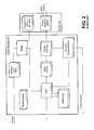
- Figure 2 is an electrical block diagram of the conventional electric power steering system of the prior art showing a disconnect relay disposed between a power input and at least one power device;
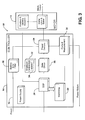
- Figure 3 is an electrical block diagram of a first embodiment of an electric power steering system of the present invention showing a shutdown mechanism having a MOSFET disposed between a power input and a gate drive device;
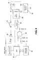
- Figure 4 is an electrical schematic of part of a controller of the system showing an interface between a processor, the shutdown mechanism, and a gate drive device;
- Figure 5 is an electrical schematic of part of the system showing a plurality of MOSFETs implemented as the at least one power device;
- FIG. 6 is a detailed electrical schematic of the shutdown mechanism of the first embodiment of the present invention.
- Figure 7 is an electrical block diagram of a second embodiment of the electric power steering system of the present invention showing a shutdown mechanism having a buck-boost converter disposed between the power input and the gate drive device.
- an electric power steering system 10 for a vehicle is shown.
- the system 10 includes an electric power steering motor 12 for providing assistance in turning a steering wheel (not shown) of the vehicle by reducing the amount of effort that must be exerted by the driver.
- the system 10 also includes a controller 14 for controlling the electrical power supplied to the motor 12.
- the controller 14 includes a power input 16 for receiving electrical power.
- the electrical power is supplied by one or more batteries (not shown) and has a voltage of about 12 V.
- batteries not shown
- voltage of about 12 V.
- those skilled in the art realize other sources of the electrical power in the vehicle may be implemented and that other voltages may alternatively be suitable.
- the controller 14 may include a battery line filter 18 electrically connected to the power input 16.
- the battery line filter 18 protects the controller 14 from surges or other electrically anomalies.
- the battery line filter 18 preferably includes a plurality of capacitors 20 and an inductor 22.
- those skilled in the art realize other suitable embodiments to implement the battery line filter 18.
- the controller 14 also includes at least one power device 24 electrically connected to the power input 16. Specifically, in the illustrated embodiment, the at least one power device 24 is electrically connected to the battery line filter 18. The at least one power device 24 is also electrically connected to the electric power steering motor 12. In operation, the at least one power device receives electrical power and variably provides the electrical power to the electric power steering motor.
- the at least one power device 24 is preferably implemented as a plurality of power transistors 25, as shown in Figure 5 . More specifically, the power transistors 25 may be power MOSFETs. However, other devices for implementing the at least one power device 24 may utilized in the alternative.
- the controller 14 further includes a gate drive device 26 electrically connected to the at least one power device 24 for regulating operation of the at least one power device 24.
- the power transistors 25 of the at least one power device 24 inherently enter a high impedance state, i.e., a shutdown state, if the gate of the power transistors falls below a threshold turn-on voltage.
- the gate drive device 26 supplies the necessary gate voltage of the power transistors 25 above a threshold turn-on level.
- the gate drive device 26 also regulates the amount of electric power provided to the at least one power device 24, and thus to the motor 12, in a variable fashion. This variation in power changes the amount of power steering assist provided by the motor 12 depending on certain vehicle conditions, as described further below.
- the controller 14 further includes a plurality of gate discharge resistors 27.
- each gate discharge resistor 27 is electrically connected between the source and the gate of the MOSFET.
- the gate discharge resistor 27 assists in discharging the MOSFET, thus disconnecting power from the motor 12.
- the power devices 24 may alternative be implemented as p-channel MOSFETs. In such implementations, the p-channel MOSFETs disconnect power from the motor 12 when a pull-up resistor (not shown) charges the MOSFET gate when the gate of the MOSFET goes high impedance.
- the controller 14 also includes a processor 28 electrically connected to the gate drive device 26 for controlling the gate drive device 26. Control of the gate drive device 26 is based on at least one signal input to the processor 28 for regulating the amount of power supplied by the at least one power device 24 to the power steering motor 12.
- the processor 28 is preferably a digital signal processor (DSP) as is well known to those skilled in the art.
- the processor 28 may include one or more signal inputs that are used for determining the amount of power to be supplied to the power steering motor. These inputs may include, but are not limited to, the electric current flowing through the at least one power device 24, the speed (velocity) of the motor 12, the positioning of a rotor of the motor 12, and the speed (velocity) of the vehicle.
- the controller 14 may also include a watchdog unit 29 for monitoring the operational status of the processor 28.
- the watchdog unit 29 is preferably a microprocessor electrically connected to the processor 28.
- the controller 12 may include a current sensor 30 electrically connected to the at least one power device.
- the current sensor 30 is in communication with the processor 28. More specifically, in the illustrated embodiment, the current sensor 30 is electrically connected to the processor 28.
- the controller 14 further includes a shutdown mechanism 32.
- the shutdown mechanism 32 is electrically connected between the gate drive device 26 and the power input 16. More specifically, in the illustrated embodiment, the shutdown mechanism 32 is electrically disposed between the battery line filter 18 and the gate drive device 26.
- the shutdown mechanism 32 isolates electrical power from the gate drive device 16 in response to a shutdown condition.
- the shutdown condition could be a system fault as well known to those skilled in the art. This electrical disconnection of the gate drive device 16 prevents the at least one power device 24 from providing electric power to the power steering motor 12.
- the shutdown mechanism 32 includes a metal-oxide semiconductor field effect transistor (MOSFET) 34.
- the MOSFET 34 of the first embodiment is implemented as a p-channel MOSFET.
- One suitable device for implementing the MOSFET 34 is a model number FDN5618P device, manufactured by Fairchild Semiconductor Corporation of South Portland, Maine and San Jose, California.
- the FDN5618P is a 60 V p-channel power MOSFET.
- the shutdown mechanism 32 may include alternative devices, other than the MOSFET 34, to provide switching of electric current, as described in further detail below.
- the MOSFET 34 of the first embodiment has a source (not labeled) electrically connected to the battery line filter 18, and thus electrically connected to the power input 16.
- a drain (not labeled) of the MOSFET 34 is electrically connected to the gate drive device 26.
- a gate (not labeled) of the MOSFET 34 receives an enable signal, which controls the switching of electric current by the MOSFET 34 between the source and the drain.
- the shutdown mechanism 32 of the first embodiment also includes a bipolar junction transistor (BJT) 36 electrically connected to the MOSFET 34.
- the BJT 36 is an NPN-type transistor.
- an AND gate 38 is electrically connected to a base (not labeled) of the BJT 36 for activating the BJT 36.
- a pair of enabling inputs must both be active to prevent the MOSFET 34 from disconnecting power from the gate drive device 26.
- These enabling inputs to the AND gate 38 may be produced by different signal sources or a common signal source.
- one input is provided by the processor 28 and the other input is provided by the watchdog unit 29.
- the shutdown mechanism 32 could be implemented without the AND gate 38 to require only one enabling input for the MOSFET 34.
- a collector (not labeled) of the BJT 36 is electrically connected to the gate of the MOSFET 34.
- An emitter (not labeled) of the BJT 36 is electrically connected to ground.
- the BJT 36 grounds the gate of the MOSFET 34, forcing the MOSFET 34 p-channel to allow the flow of current to the gate drive device 26.
- the gate drive device 26 operates normally, allowing the power transistors of the at least one power devices 24, to provide power to the electric motor 12.
- the shutdown mechanism 32 of the first embodiment further includes a gate charge resistor 39.
- the gate charge resistor 39 is electrically connected between the source and the gate of the MOSFET 34. When the input to the gate of the MOSFET 34 goes high impedance, the gate charge resistor 39 assists in positively charging the MOSFET 34 gate, thus removing the MOSFET 34 p-channel and disconnecting power from the gate drive device 26 and the at least one power device 24.
- the gate charge resistor 39 may also commonly be referred to as a pull-up resistor.
- the shutdown mechanism 32 of the first embodiment also includes a test circuit 40 for testing whether the MOSFET 34 is functioning properly before normal operation of the MOSFET 34.
- the test circuit 40 implements a voltage divider with a pair of resistors 42, 44 electrically connected to the drain of the MOSFET 34 as shown specifically in Figure 6 .
- the shutdown mechanism 32 of the first embodiment further includes a Zener diode 46 electrically connected between the source and the gate of the MOSFET 34.
- the Zener diode 46 provides load dump protection for the MOSFET 34. Specifically, the Zener diode 46 protects the MOSFET 34 by ensuring that the gate-to-source voltage does not exceed its rated value.
- the shutdown mechanism 32 may also include a Schottky diode 48 electrically connected between the power input 16 and the gate drive device 26.
- the Schottky diode 48 is electrically connected between the inductor 22 of the battery line filter 18 and the source of the MOSFET 34.
- the Schottky diode 48 prevents a back flow of current to the one or more batteries electrically connected to the power input 16.
- the shutdown mechanism 32 may further include a gate drive bypass capacitor 49.
- This bypass capacitor 49 is electrically connected between the test circuit 40 and the gate drive device 28, as shown in Figure 4 .
- the bypass capacitor 49 preferably has a capacitance of about 10 ⁇ F. However, other sizes for the bypass capacitor 49 will be realized by those skilled in the art.
- bypass capacitor 49 is sized relatively small (e.g., 10 ⁇ F) when compared to a bulk capacitor of the converter, which is on the order of 10,000 ⁇ F.
- electric power is removed from the at least one power device 24 very quickly once one of the enable signals is removed, typically on the order of 10 ms.
- the processor 28 and test circuit 40 may be utilized to measure the speed of this discharge, to verify proper function.
- electric energy generated by the motor 12 may flow back to the battery.
- electric power is effectively scavenged from the electric power steering system 10. This effect is increasingly important in electric and hybrid electric vehicles.
- the shutdown mechanism 32 may be implemented with devices other than the p-channel MOSFET 34.
- the shutdown mechanism 32 could alternatively include a controlled buck-boost converter 50, as shown in Figure 7 .
- the buck-boost converter 50 boosts the voltage to the gate drive device while being able to disconnect power to the date drive device. Boosting the voltage provides a more efficient operation of the power transistors of the at least one power device 24 during a low voltage event.
- buck-boost converters can transmit power through an inductor or capacitor. Therefore, if a power device in the buck-boost converter fails 50, it stops transmitting power to the gate drive device 26 and the at least one power device 24.
Landscapes
- Engineering & Computer Science (AREA)
- Chemical & Material Sciences (AREA)
- Combustion & Propulsion (AREA)
- Transportation (AREA)
- Mechanical Engineering (AREA)
- Power Steering Mechanism (AREA)
Abstract
Description
- The invention relates to electric power steering systems. Specifically, the invention relates to disconnecting power from a motor of an electric power steering system.
- Modem vehicles typically offer power steering systems to aid the driver in turning the wheels of the vehicle via the steering wheel. This assistance is most often needed at slow or stopped vehicle speeds. Conversely, very little assistance is needed when the vehicle is traveling at higher speeds.
- Conventional power steering is accomplished using hydraulic mechanisms. However, electric power steering systems have recently become more commonplace. Electric power steering systems include an electric motor operatively connected to the wheels of the vehicle to provide assist when the driver turns the steering wheel. The amount of electrical power provided to the electric motor is typically varied based on a number of factors, including, but not limited to, the speed of the vehicle. A control diagram for such a prior art system can be seen in
Figure 1 . - In case of a fault in the electric power steering systems, it is often necessary and prudent to disconnect all electric power from the electric motor, thus resulting in manual steering of the vehicle. This disconnection of power from the electric motor in the prior art is accomplished by one or more relays, as can be seen in prior art
Figures 1 and2 . More specifically, as shown inFigure 2 , a disconnect relay is electrically connected between a power input and at least one power device. - Unfortunately, this prior art system has numerous shortcomings. For instance, the resistance from the relay contacts is undesirable as they provide a source of power loss in the system. Furthermore, the electromechanical relays are physically large and expensive due to the large amount of current they need to carry, as well as often being unreliable. Moreover, multiple (redundant) battery measurement is required on both sides of the relay to ensure proper operation.
- The present invention attempts to solve these and other problems of prior art electric power steering systems.
- The subject invention provides an electric power steering system for a vehicle. The system includes an electric power steering motor operatively connected to at least one wheel of the vehicle for assisting in turning the at least one wheel of the vehicle. At least one power device is electrically connected to a power input for receiving electrical power and to the motor for providing electrical power to the motor. The system also includes a gate drive device electrically connected to the at least one power device for regulating operation of the at least one power device. A shutdown mechanism is electrically connected between the gate drive device and the power input. The shutdown mechanism isolates electrical power from the gate drive device in response to a shutdown condition to prevent the at least one power device from providing electric power to the power steering motor.
- By implementing the shutdown mechanism between the power input and the gate drive device, several advantages are achieved over prior art systems. First, because of the relatively small size of a bypass capacitor (not shown), electric power is removed from the at least one power device very quickly once one of the enable signals is removed. Furthermore, electric energy generated by the motor may flow back to a battery of the vehicle.
- Other advantages of the present invention will be readily appreciated, as the same becomes better understood by reference to the following detailed description when considered in connection with the accompanying drawings wherein:
-
Figure 1 is a control diagram showing operation of a conventional electric power steering system of the prior art; -
Figure 2 is an electrical block diagram of the conventional electric power steering system of the prior art showing a disconnect relay disposed between a power input and at least one power device; -
Figure 3 is an electrical block diagram of a first embodiment of an electric power steering system of the present invention showing a shutdown mechanism having a MOSFET disposed between a power input and a gate drive device; -
Figure 4 is an electrical schematic of part of a controller of the system showing an interface between a processor, the shutdown mechanism, and a gate drive device; -
Figure 5 is an electrical schematic of part of the system showing a plurality of MOSFETs implemented as the at least one power device; -
Figure 6 is a detailed electrical schematic of the shutdown mechanism of the first embodiment of the present invention; and -
Figure 7 is an electrical block diagram of a second embodiment of the electric power steering system of the present invention showing a shutdown mechanism having a buck-boost converter disposed between the power input and the gate drive device. - Referring to Figures, wherein like numerals indicate like parts throughout the several views, an electric
power steering system 10 for a vehicle is shown. With reference toFigure 3 , thesystem 10 includes an electricpower steering motor 12 for providing assistance in turning a steering wheel (not shown) of the vehicle by reducing the amount of effort that must be exerted by the driver. Thesystem 10 also includes acontroller 14 for controlling the electrical power supplied to themotor 12. - The
controller 14 includes apower input 16 for receiving electrical power. Typically, the electrical power is supplied by one or more batteries (not shown) and has a voltage of about 12 V. However, those skilled in the art realize other sources of the electrical power in the vehicle may be implemented and that other voltages may alternatively be suitable. - The
controller 14 may include abattery line filter 18 electrically connected to thepower input 16. Thebattery line filter 18 protects thecontroller 14 from surges or other electrically anomalies. In an illustrated embodiment, as shown inFigure 6 , thebattery line filter 18 preferably includes a plurality ofcapacitors 20 and aninductor 22. However, those skilled in the art realize other suitable embodiments to implement thebattery line filter 18. - Referring to
Figure 3 , thecontroller 14 also includes at least onepower device 24 electrically connected to thepower input 16. Specifically, in the illustrated embodiment, the at least onepower device 24 is electrically connected to thebattery line filter 18. The at least onepower device 24 is also electrically connected to the electricpower steering motor 12. In operation, the at least one power device receives electrical power and variably provides the electrical power to the electric power steering motor. The at least onepower device 24 is preferably implemented as a plurality ofpower transistors 25, as shown inFigure 5 . More specifically, thepower transistors 25 may be power MOSFETs. However, other devices for implementing the at least onepower device 24 may utilized in the alternative. - The
controller 14 further includes agate drive device 26 electrically connected to the at least onepower device 24 for regulating operation of the at least onepower device 24. Thepower transistors 25 of the at least onepower device 24 inherently enter a high impedance state, i.e., a shutdown state, if the gate of the power transistors falls below a threshold turn-on voltage. As such, in normal operation, thegate drive device 26 supplies the necessary gate voltage of thepower transistors 25 above a threshold turn-on level. - The
gate drive device 26 also regulates the amount of electric power provided to the at least onepower device 24, and thus to themotor 12, in a variable fashion. This variation in power changes the amount of power steering assist provided by themotor 12 depending on certain vehicle conditions, as described further below. - The
controller 14 further includes a plurality ofgate discharge resistors 27. When thepower devices 24 are implemented as n-channel MOSFETs, eachgate discharge resistor 27 is electrically connected between the source and the gate of the MOSFET. When the gate of the MOSFET goes high impedance, thegate discharge resistor 27 assists in discharging the MOSFET, thus disconnecting power from themotor 12. However, thepower devices 24 may alternative be implemented as p-channel MOSFETs. In such implementations, the p-channel MOSFETs disconnect power from themotor 12 when a pull-up resistor (not shown) charges the MOSFET gate when the gate of the MOSFET goes high impedance. - The
controller 14 also includes aprocessor 28 electrically connected to thegate drive device 26 for controlling thegate drive device 26. Control of thegate drive device 26 is based on at least one signal input to theprocessor 28 for regulating the amount of power supplied by the at least onepower device 24 to thepower steering motor 12. Theprocessor 28 is preferably a digital signal processor (DSP) as is well known to those skilled in the art. - As described above, the
processor 28 may include one or more signal inputs that are used for determining the amount of power to be supplied to the power steering motor. These inputs may include, but are not limited to, the electric current flowing through the at least onepower device 24, the speed (velocity) of themotor 12, the positioning of a rotor of themotor 12, and the speed (velocity) of the vehicle. - The
controller 14 may also include awatchdog unit 29 for monitoring the operational status of theprocessor 28. Thewatchdog unit 29 is preferably a microprocessor electrically connected to theprocessor 28. - To provide a signal corresponding to the current flowing through the at least one
power device 24, thecontroller 12 may include acurrent sensor 30 electrically connected to the at least one power device. Thecurrent sensor 30 is in communication with theprocessor 28. More specifically, in the illustrated embodiment, thecurrent sensor 30 is electrically connected to theprocessor 28. - The
controller 14 further includes ashutdown mechanism 32. Theshutdown mechanism 32 is electrically connected between thegate drive device 26 and thepower input 16. More specifically, in the illustrated embodiment, theshutdown mechanism 32 is electrically disposed between thebattery line filter 18 and thegate drive device 26. Theshutdown mechanism 32 isolates electrical power from thegate drive device 16 in response to a shutdown condition. The shutdown condition could be a system fault as well known to those skilled in the art. This electrical disconnection of thegate drive device 16 prevents the at least onepower device 24 from providing electric power to thepower steering motor 12. - In a first embodiment, as shown in
Figure 6 , theshutdown mechanism 32 includes a metal-oxide semiconductor field effect transistor (MOSFET) 34. TheMOSFET 34 of the first embodiment is implemented as a p-channel MOSFET. One suitable device for implementing theMOSFET 34 is a model number FDN5618P device, manufactured by Fairchild Semiconductor Corporation of South Portland, Maine and San Jose, California. The FDN5618P is a 60 V p-channel power MOSFET. Of course, other suitable devices may be implemented as theMOSFET 34. Furthermore, in other embodiments, theshutdown mechanism 32 may include alternative devices, other than theMOSFET 34, to provide switching of electric current, as described in further detail below. - The
MOSFET 34 of the first embodiment has a source (not labeled) electrically connected to thebattery line filter 18, and thus electrically connected to thepower input 16. A drain (not labeled) of theMOSFET 34 is electrically connected to thegate drive device 26. A gate (not labeled) of theMOSFET 34 receives an enable signal, which controls the switching of electric current by theMOSFET 34 between the source and the drain. - The
shutdown mechanism 32 of the first embodiment also includes a bipolar junction transistor (BJT) 36 electrically connected to theMOSFET 34. Specifically, theBJT 36 is an NPN-type transistor. In the first embodiment, an ANDgate 38 is electrically connected to a base (not labeled) of theBJT 36 for activating theBJT 36. With this configuration, a pair of enabling inputs must both be active to prevent theMOSFET 34 from disconnecting power from thegate drive device 26. These enabling inputs to the ANDgate 38 may be produced by different signal sources or a common signal source. In the first embodiment, as shown inFigures 4 and6 , one input is provided by theprocessor 28 and the other input is provided by thewatchdog unit 29. However, in other embodiments, theshutdown mechanism 32 could be implemented without the ANDgate 38 to require only one enabling input for theMOSFET 34. - A collector (not labeled) of the
BJT 36 is electrically connected to the gate of theMOSFET 34. An emitter (not labeled) of theBJT 36 is electrically connected to ground. When activated, the BJT 36 grounds the gate of theMOSFET 34, forcing the MOSFET 34 p-channel to allow the flow of current to thegate drive device 26. In turn, thegate drive device 26 operates normally, allowing the power transistors of the at least onepower devices 24, to provide power to theelectric motor 12. - The
shutdown mechanism 32 of the first embodiment further includes agate charge resistor 39. Thegate charge resistor 39 is electrically connected between the source and the gate of theMOSFET 34. When the input to the gate of theMOSFET 34 goes high impedance, thegate charge resistor 39 assists in positively charging theMOSFET 34 gate, thus removing the MOSFET 34 p-channel and disconnecting power from thegate drive device 26 and the at least onepower device 24. Thegate charge resistor 39 may also commonly be referred to as a pull-up resistor. - Referring to
Figures 4 and6 , theshutdown mechanism 32 of the first embodiment also includes atest circuit 40 for testing whether theMOSFET 34 is functioning properly before normal operation of theMOSFET 34. Thetest circuit 40 implements a voltage divider with a pair ofresistors MOSFET 34 as shown specifically inFigure 6 . - The
shutdown mechanism 32 of the first embodiment further includes aZener diode 46 electrically connected between the source and the gate of theMOSFET 34. TheZener diode 46 provides load dump protection for theMOSFET 34. Specifically, theZener diode 46 protects theMOSFET 34 by ensuring that the gate-to-source voltage does not exceed its rated value. - The
shutdown mechanism 32 may also include aSchottky diode 48 electrically connected between thepower input 16 and thegate drive device 26. In the first embodiment, theSchottky diode 48 is electrically connected between theinductor 22 of thebattery line filter 18 and the source of theMOSFET 34. TheSchottky diode 48 prevents a back flow of current to the one or more batteries electrically connected to thepower input 16. - The
shutdown mechanism 32 may further include a gatedrive bypass capacitor 49. Thisbypass capacitor 49 is electrically connected between thetest circuit 40 and thegate drive device 28, as shown inFigure 4 . Thebypass capacitor 49 preferably has a capacitance of about 10 µF. However, other sizes for thebypass capacitor 49 will be realized by those skilled in the art. - By implementing the
shutdown mechanism 32 between thepower input 16 and thegate drive device 26, several advantages are achieved over prior art systems. First, thebypass capacitor 49 is sized relatively small (e.g., 10 µF) when compared to a bulk capacitor of the converter, which is on the order of 10,000 µF. As such, electric power is removed from the at least onepower device 24 very quickly once one of the enable signals is removed, typically on the order of 10 ms. Theprocessor 28 andtest circuit 40 may be utilized to measure the speed of this discharge, to verify proper function. - Furthermore, electric energy generated by the motor 12 (e.g., due to the turning of the wheels and/or the steering wheel) may flow back to the battery. As such, electric power is effectively scavenged from the electric
power steering system 10. This effect is increasingly important in electric and hybrid electric vehicles. - As mentioned above, the
shutdown mechanism 32 may be implemented with devices other than the p-channel MOSFET 34. For example, in a second embodiment, theshutdown mechanism 32 could alternatively include a controlled buck-boost converter 50, as shown inFigure 7 . The buck-boost converter 50 boosts the voltage to the gate drive device while being able to disconnect power to the date drive device. Boosting the voltage provides a more efficient operation of the power transistors of the at least onepower device 24 during a low voltage event. Furthermore, buck-boost converters can transmit power through an inductor or capacitor. Therefore, if a power device in the buck-boost converter fails 50, it stops transmitting power to thegate drive device 26 and the at least onepower device 24. - The present invention has been described herein in an illustrative manner, and it is to be understood that the terminology which has been used is intended to be in the nature of words of description rather than of limitation. Obviously, many modifications and variations of the invention are possible in light of the above teachings. The invention may be practiced otherwise than as specifically described within the scope of the appended claims.
Claims (15)
- A controller (14) for an electric power steering system (10) having an electric power steering motor (12), said controller (14) comprising:a power input (16) for receiving electrical power;at least one power device (24) electrically connected to said power input (16) for receiving electrical power;said at least one power device (24) electrically connectable to the power steering motor (12) for variably providing electrical power to the motor (12);a gate drive device (26) electrically connected to said at least one power device (24) for regulating operation of said at least one power device (24); anda shutdown mechanism (32) electrically connected between said gate drive device (26) and said power input (16) for isolating electrical power from said gate drive device (26) in response to a shutdown condition to prevent said at least one power device (24) from providing electric power to the power steering motor (12).
- A controller (14) as set forth in claim 1 wherein said shutdown mechanism (32) includes a MOSFET (34) having a source electrically connected to said power input (16), a drain electrically connected to said gate drive device (26), and a gate for receiving an enable signal.
- A controller (14) as set forth in claim 2 further comprising a gate charge resistor (39) electrically connected between said source of said MOSFET (34) and ground for deactivating said MOSFET (34).
- A controller (14) as set forth in claim 2 further comprising a Zener diode (46) electrically connected between said source and said gate of said MOSFET (34).
- A controller (14) as set forth in claim 2 wherein said shutdown mechanism (32) further includes an AND gate (38) having inputs for receiving enabling signals and an output.
- A controller (14) as set forth in claim 5 wherein said shutdown mechanism (32) further includes a bipolar junction transistor (BJT) (36) having a base electrically connected to said output of said AND gate (38), a collector electrically connected to said gate of said MOSFET (34), and an emitter electrically connected to ground.
- A controller (14) as set forth in claim 2 wherein said shutdown mechanism (32) further includes a test circuit (40) electrically connected to said MOSFET (34) for testing whether said MOSFET (34) is functioning properly.
- A controller (14) as set forth in claim 2 wherein said shutdown mechanism (32) further includes a capacitor (49) electrically connected to said drain of said MOSFET (34).
- A controller (14) as set forth in claim 1 further comprising a Schottky diode (48) electrically connected between said power input (16) and said gate drive device (26) for providing protection to a battery electrically connected to said power input (16).
- A controller (14) as set forth in claim 1 further comprising a processor (28) electrically connected to said gate drive device (26) for controlling said gate drive device (26) based on at least one input to regulate the amount of power supplied by said at least one power device (24) to the power steering motor (12).
- A controller (14) as set forth in claim 10 further comprising a current sensor (30) electrically connected to said at least one power device (24) and in communication with said processor (28) for supplying said processor (28) with a signal corresponding to an amount of current flowing through said at least one power device (24).
- A controller (14) as set forth in claim 1 wherein said at least one power device (24) is further defined as a plurality of power transistors.
- controller (14) as set forth in claim 12 further comprising a plurality of gate discharge resistors wherein each gate discharge resistor is electrically connected between one of said plurality of power transistors (25) and ground for deactivating said plurality of power transistors (25).
- A controller (14) as set forth in claim 1 wherein said shutdown mechanism (32) includes a buck-boost converter (50) electrically connected to said power input (16) and said gate drive device (26).
- An electric power steering system (10) for a vehicle comprising:an electric power steering motor (12) operatively connected to at least one wheel of the vehicle for assisting in turning the at least one wheel of the vehicle; anda controller as claimed in any one of claims 1 to 14.
Priority Applications (1)
| Application Number | Priority Date | Filing Date | Title |
|---|---|---|---|
| PL09160172T PL2123539T3 (en) | 2008-05-23 | 2009-05-13 | Electric Power Steering System, Controller, and Method of Operation |
Applications Claiming Priority (2)
| Application Number | Priority Date | Filing Date | Title |
|---|---|---|---|
| US5569108P | 2008-05-23 | 2008-05-23 | |
| US12/434,891 US8051945B2 (en) | 2008-05-23 | 2009-05-04 | Electric power steering system, controller, and method of operation |
Publications (2)
| Publication Number | Publication Date |
|---|---|
| EP2123539A1 true EP2123539A1 (en) | 2009-11-25 |
| EP2123539B1 EP2123539B1 (en) | 2012-07-11 |
Family
ID=40941440
Family Applications (1)
| Application Number | Title | Priority Date | Filing Date |
|---|---|---|---|
| EP09160172A Not-in-force EP2123539B1 (en) | 2008-05-23 | 2009-05-13 | Electric Power Steering System, Controller, and Method of Operation |
Country Status (3)
| Country | Link |
|---|---|
| US (1) | US8051945B2 (en) |
| EP (1) | EP2123539B1 (en) |
| PL (1) | PL2123539T3 (en) |
Families Citing this family (6)
| Publication number | Priority date | Publication date | Assignee | Title |
|---|---|---|---|---|
| ITMO20030259A1 (en) | 2003-09-25 | 2005-03-26 | Gambro Lundia Ab | USER INTERFACE FOR A TREATMENT MACHINE |
| JP5409692B2 (en) * | 2011-04-18 | 2014-02-05 | 三菱電機株式会社 | Electric power steering device |
| US9799627B2 (en) * | 2012-01-19 | 2017-10-24 | Semiconductor Components Industries, Llc | Semiconductor package structure and method |
| US9634604B2 (en) | 2013-04-30 | 2017-04-25 | Nxp Usa, Inc. | Device for controlling a multi-phase motor |
| CN109194319B (en) * | 2018-08-13 | 2022-07-05 | 北方电子研究院安徽有限公司 | PMOS tube driving circuit |
| KR20230140934A (en) * | 2022-03-30 | 2023-10-10 | 에이치엘만도 주식회사 | Steering control apparatus and method |
Citations (5)
| Publication number | Priority date | Publication date | Assignee | Title |
|---|---|---|---|---|
| EP0337645A1 (en) | 1988-04-14 | 1989-10-18 | Mitsubishi Denki Kabushiki Kaisha | Electric power steering device having a fail-safe relay |
| EP0689986A1 (en) * | 1994-06-30 | 1996-01-03 | Mitsubishi Denki Kabushiki Kaisha | Control device of power steering motor capable of preventing motor-current-induced vibration and noise |
| US20060066270A1 (en) * | 2004-09-22 | 2006-03-30 | Nsk Ltd. | Controller for motor to be mounted on vehicle and electric power steering device and electric brake device using thereof |
| EP1737116A1 (en) * | 2004-03-19 | 2006-12-27 | Mitsubishi Denki Kabushiki Kaisha | Motor controller |
| JP2007099066A (en) * | 2005-10-04 | 2007-04-19 | Nsk Ltd | Electric power steering device |
Family Cites Families (16)
| Publication number | Priority date | Publication date | Assignee | Title |
|---|---|---|---|---|
| US4621327A (en) * | 1984-06-13 | 1986-11-04 | Nartron Corporation | Electronic power steering method and apparatus |
| US4660671A (en) * | 1985-10-23 | 1987-04-28 | Trw Inc. | Electric steering gear |
| JPH0796387B2 (en) * | 1986-03-31 | 1995-10-18 | 本田技研工業株式会社 | Electric power steering device |
| JPH0796388B2 (en) * | 1987-04-13 | 1995-10-18 | 株式会社日立製作所 | Electric power steering device |
| US5150021A (en) * | 1989-09-18 | 1992-09-22 | Jidosha Kiki Co., Ltd. | Method of controlling electric power steering apparatus |
| DE69217084T2 (en) * | 1991-10-10 | 1997-05-07 | Koyo Seiko Co | Electric power steering |
| JP3100834B2 (en) * | 1994-06-30 | 2000-10-23 | 三菱電機株式会社 | Electric power steering circuit device |
| JP3644835B2 (en) * | 1999-01-18 | 2005-05-11 | 三菱電機株式会社 | Electric power steering circuit device |
| JP3486749B2 (en) * | 2000-04-05 | 2004-01-13 | 本田技研工業株式会社 | Electric power steering device |
| JP3774624B2 (en) * | 2000-10-18 | 2006-05-17 | 三菱電機株式会社 | Electric power steering device |
| US6611411B2 (en) * | 2001-04-06 | 2003-08-26 | General Electric Company | Trip signal verifying method and apparatus |
| JP3638269B2 (en) * | 2002-03-14 | 2005-04-13 | 三菱電機株式会社 | Electric power steering device |
| JP2003309384A (en) * | 2002-04-17 | 2003-10-31 | Denso Corp | Current switching circuit device and electric power steering circuit device |
| JP4471752B2 (en) * | 2004-07-06 | 2010-06-02 | 日立オートモティブシステムズ株式会社 | Electric power steering control device and electric power steering system |
| JP4475403B2 (en) * | 2004-09-07 | 2010-06-09 | 三菱電機株式会社 | Electric power steering control device |
| EP1767435A2 (en) * | 2005-09-27 | 2007-03-28 | Nsk Ltd. | Electric power steering control device |
-
2009
- 2009-05-04 US US12/434,891 patent/US8051945B2/en active Active
- 2009-05-13 EP EP09160172A patent/EP2123539B1/en not_active Not-in-force
- 2009-05-13 PL PL09160172T patent/PL2123539T3/en unknown
Patent Citations (5)
| Publication number | Priority date | Publication date | Assignee | Title |
|---|---|---|---|---|
| EP0337645A1 (en) | 1988-04-14 | 1989-10-18 | Mitsubishi Denki Kabushiki Kaisha | Electric power steering device having a fail-safe relay |
| EP0689986A1 (en) * | 1994-06-30 | 1996-01-03 | Mitsubishi Denki Kabushiki Kaisha | Control device of power steering motor capable of preventing motor-current-induced vibration and noise |
| EP1737116A1 (en) * | 2004-03-19 | 2006-12-27 | Mitsubishi Denki Kabushiki Kaisha | Motor controller |
| US20060066270A1 (en) * | 2004-09-22 | 2006-03-30 | Nsk Ltd. | Controller for motor to be mounted on vehicle and electric power steering device and electric brake device using thereof |
| JP2007099066A (en) * | 2005-10-04 | 2007-04-19 | Nsk Ltd | Electric power steering device |
Also Published As
| Publication number | Publication date |
|---|---|
| US20090288907A1 (en) | 2009-11-26 |
| EP2123539B1 (en) | 2012-07-11 |
| PL2123539T3 (en) | 2012-12-31 |
| US8051945B2 (en) | 2011-11-08 |
Similar Documents
| Publication | Publication Date | Title |
|---|---|---|
| US8051945B2 (en) | Electric power steering system, controller, and method of operation | |
| US10399518B2 (en) | Relay device and power supply device | |
| CN109130893B (en) | Battery connection systems for electric and/or hybrid vehicles | |
| US8206861B2 (en) | Intermediate circuit with a first switch for switching a fuel cell stack and second switch for short-circuting the fuel stack, fuel cell system with an intermediate circuit, and method for controlling the intermediate circuit | |
| CN108886248B (en) | Relay device | |
| US20140307495A1 (en) | Driver for target switching element and control system for machine using the same | |
| US9806643B2 (en) | Drive control apparatus for electric motor | |
| US20140055887A1 (en) | Motor drive device | |
| CN110231560B (en) | Inductive load control device | |
| CN101883706B (en) | Electric Power Steering | |
| US20150123637A1 (en) | Power supply device | |
| US12142909B2 (en) | Mitigation of microcontroller restart from post-failure shutdown condition | |
| WO2011152086A1 (en) | Power supply device | |
| KR102502388B1 (en) | Control device and method for EPS power supply in vehicle | |
| US11323058B2 (en) | Drive controller for electric motor | |
| CN104052372A (en) | Motor drive device | |
| US10998713B2 (en) | Relay device | |
| WO2022145271A1 (en) | Backup power supply control system, backup power supply system, and mobile body | |
| US11909254B2 (en) | Motor vehicle control device having a switch-on and switch-off function for at least one electrical consumer that is to be controlled by the motor vehicle control device | |
| WO2020217780A1 (en) | Load driving device | |
| WO2023204081A1 (en) | Load driving device | |
| JP7107159B2 (en) | Vehicle backup power supply | |
| JP7182650B2 (en) | Systems for controlling switches, switching arms and electrical installations | |
| JP7713164B2 (en) | Vehicle control device | |
| US10826486B2 (en) | Switching driving circuit, switching circuit, and power supply device |
Legal Events
| Date | Code | Title | Description |
|---|---|---|---|
| PUAI | Public reference made under article 153(3) epc to a published international application that has entered the european phase |
Free format text: ORIGINAL CODE: 0009012 |
|
| AK | Designated contracting states |
Kind code of ref document: A1 Designated state(s): AT BE BG CH CY CZ DE DK EE ES FI FR GB GR HR HU IE IS IT LI LT LU LV MC MK MT NL NO PL PT RO SE SI SK TR |
|
| 17P | Request for examination filed |
Effective date: 20100420 |
|
| 17Q | First examination report despatched |
Effective date: 20100610 |
|
| RAP1 | Party data changed (applicant data changed or rights of an application transferred) |
Owner name: GM GLOBAL TECHNOLOGY OPERATIONS, INC. |
|
| RAP1 | Party data changed (applicant data changed or rights of an application transferred) |
Owner name: GM GLOBAL TECHNOLOGY OPERATIONS LLC |
|
| GRAP | Despatch of communication of intention to grant a patent |
Free format text: ORIGINAL CODE: EPIDOSNIGR1 |
|
| GRAS | Grant fee paid |
Free format text: ORIGINAL CODE: EPIDOSNIGR3 |
|
| GRAA | (expected) grant |
Free format text: ORIGINAL CODE: 0009210 |
|
| AK | Designated contracting states |
Kind code of ref document: B1 Designated state(s): AT BE BG CH CY CZ DE DK EE ES FI FR GB GR HR HU IE IS IT LI LT LU LV MC MK MT NL NO PL PT RO SE SI SK TR |
|
| REG | Reference to a national code |
Ref country code: GB Ref legal event code: FG4D |
|
| REG | Reference to a national code |
Ref country code: CH Ref legal event code: EP |
|
| REG | Reference to a national code |
Ref country code: AT Ref legal event code: REF Ref document number: 565950 Country of ref document: AT Kind code of ref document: T Effective date: 20120715 |
|
| REG | Reference to a national code |
Ref country code: IE Ref legal event code: FG4D |
|
| REG | Reference to a national code |
Ref country code: DE Ref legal event code: R096 Ref document number: 602009008158 Country of ref document: DE Effective date: 20120906 |
|
| REG | Reference to a national code |
Ref country code: NL Ref legal event code: VDEP Effective date: 20120711 |
|
| REG | Reference to a national code |
Ref country code: AT Ref legal event code: MK05 Ref document number: 565950 Country of ref document: AT Kind code of ref document: T Effective date: 20120711 |
|
| RAP2 | Party data changed (patent owner data changed or rights of a patent transferred) |
Owner name: GM GLOBAL TECHNOLOGY OPERATIONS LLC Owner name: STEERING SOLUTIONS IP HOLDING CORPORATION |
|
| REG | Reference to a national code |
Ref country code: LT Ref legal event code: MG4D Effective date: 20120711 |
|
| REG | Reference to a national code |
Ref country code: PL Ref legal event code: T3 |
|
| PG25 | Lapsed in a contracting state [announced via postgrant information from national office to epo] |
Ref country code: IS Free format text: LAPSE BECAUSE OF FAILURE TO SUBMIT A TRANSLATION OF THE DESCRIPTION OR TO PAY THE FEE WITHIN THE PRESCRIBED TIME-LIMIT Effective date: 20121111 Ref country code: HR Free format text: LAPSE BECAUSE OF FAILURE TO SUBMIT A TRANSLATION OF THE DESCRIPTION OR TO PAY THE FEE WITHIN THE PRESCRIBED TIME-LIMIT Effective date: 20120711 Ref country code: LT Free format text: LAPSE BECAUSE OF FAILURE TO SUBMIT A TRANSLATION OF THE DESCRIPTION OR TO PAY THE FEE WITHIN THE PRESCRIBED TIME-LIMIT Effective date: 20120711 Ref country code: FI Free format text: LAPSE BECAUSE OF FAILURE TO SUBMIT A TRANSLATION OF THE DESCRIPTION OR TO PAY THE FEE WITHIN THE PRESCRIBED TIME-LIMIT Effective date: 20120711 Ref country code: AT Free format text: LAPSE BECAUSE OF FAILURE TO SUBMIT A TRANSLATION OF THE DESCRIPTION OR TO PAY THE FEE WITHIN THE PRESCRIBED TIME-LIMIT Effective date: 20120711 Ref country code: CY Free format text: LAPSE BECAUSE OF FAILURE TO SUBMIT A TRANSLATION OF THE DESCRIPTION OR TO PAY THE FEE WITHIN THE PRESCRIBED TIME-LIMIT Effective date: 20120711 Ref country code: BE Free format text: LAPSE BECAUSE OF FAILURE TO SUBMIT A TRANSLATION OF THE DESCRIPTION OR TO PAY THE FEE WITHIN THE PRESCRIBED TIME-LIMIT Effective date: 20120711 Ref country code: NO Free format text: LAPSE BECAUSE OF FAILURE TO SUBMIT A TRANSLATION OF THE DESCRIPTION OR TO PAY THE FEE WITHIN THE PRESCRIBED TIME-LIMIT Effective date: 20121011 |
|
| PG25 | Lapsed in a contracting state [announced via postgrant information from national office to epo] |
Ref country code: GR Free format text: LAPSE BECAUSE OF FAILURE TO SUBMIT A TRANSLATION OF THE DESCRIPTION OR TO PAY THE FEE WITHIN THE PRESCRIBED TIME-LIMIT Effective date: 20121012 Ref country code: PT Free format text: LAPSE BECAUSE OF FAILURE TO SUBMIT A TRANSLATION OF THE DESCRIPTION OR TO PAY THE FEE WITHIN THE PRESCRIBED TIME-LIMIT Effective date: 20121112 Ref country code: LV Free format text: LAPSE BECAUSE OF FAILURE TO SUBMIT A TRANSLATION OF THE DESCRIPTION OR TO PAY THE FEE WITHIN THE PRESCRIBED TIME-LIMIT Effective date: 20120711 Ref country code: SE Free format text: LAPSE BECAUSE OF FAILURE TO SUBMIT A TRANSLATION OF THE DESCRIPTION OR TO PAY THE FEE WITHIN THE PRESCRIBED TIME-LIMIT Effective date: 20120711 Ref country code: SI Free format text: LAPSE BECAUSE OF FAILURE TO SUBMIT A TRANSLATION OF THE DESCRIPTION OR TO PAY THE FEE WITHIN THE PRESCRIBED TIME-LIMIT Effective date: 20120711 |
|
| PG25 | Lapsed in a contracting state [announced via postgrant information from national office to epo] |
Ref country code: NL Free format text: LAPSE BECAUSE OF FAILURE TO SUBMIT A TRANSLATION OF THE DESCRIPTION OR TO PAY THE FEE WITHIN THE PRESCRIBED TIME-LIMIT Effective date: 20120711 |
|
| PG25 | Lapsed in a contracting state [announced via postgrant information from national office to epo] |
Ref country code: EE Free format text: LAPSE BECAUSE OF FAILURE TO SUBMIT A TRANSLATION OF THE DESCRIPTION OR TO PAY THE FEE WITHIN THE PRESCRIBED TIME-LIMIT Effective date: 20120711 Ref country code: RO Free format text: LAPSE BECAUSE OF FAILURE TO SUBMIT A TRANSLATION OF THE DESCRIPTION OR TO PAY THE FEE WITHIN THE PRESCRIBED TIME-LIMIT Effective date: 20120711 Ref country code: DK Free format text: LAPSE BECAUSE OF FAILURE TO SUBMIT A TRANSLATION OF THE DESCRIPTION OR TO PAY THE FEE WITHIN THE PRESCRIBED TIME-LIMIT Effective date: 20120711 Ref country code: ES Free format text: LAPSE BECAUSE OF FAILURE TO SUBMIT A TRANSLATION OF THE DESCRIPTION OR TO PAY THE FEE WITHIN THE PRESCRIBED TIME-LIMIT Effective date: 20121022 |
|
| PLBE | No opposition filed within time limit |
Free format text: ORIGINAL CODE: 0009261 |
|
| STAA | Information on the status of an ep patent application or granted ep patent |
Free format text: STATUS: NO OPPOSITION FILED WITHIN TIME LIMIT |
|
| PG25 | Lapsed in a contracting state [announced via postgrant information from national office to epo] |
Ref country code: SK Free format text: LAPSE BECAUSE OF FAILURE TO SUBMIT A TRANSLATION OF THE DESCRIPTION OR TO PAY THE FEE WITHIN THE PRESCRIBED TIME-LIMIT Effective date: 20120711 |
|
| 26N | No opposition filed |
Effective date: 20130412 |
|
| PG25 | Lapsed in a contracting state [announced via postgrant information from national office to epo] |
Ref country code: BG Free format text: LAPSE BECAUSE OF FAILURE TO SUBMIT A TRANSLATION OF THE DESCRIPTION OR TO PAY THE FEE WITHIN THE PRESCRIBED TIME-LIMIT Effective date: 20121011 |
|
| REG | Reference to a national code |
Ref country code: DE Ref legal event code: R097 Ref document number: 602009008158 Country of ref document: DE Effective date: 20130412 |
|
| PG25 | Lapsed in a contracting state [announced via postgrant information from national office to epo] |
Ref country code: MC Free format text: LAPSE BECAUSE OF FAILURE TO SUBMIT A TRANSLATION OF THE DESCRIPTION OR TO PAY THE FEE WITHIN THE PRESCRIBED TIME-LIMIT Effective date: 20120711 |
|
| REG | Reference to a national code |
Ref country code: CH Ref legal event code: PL |
|
| GBPC | Gb: european patent ceased through non-payment of renewal fee |
Effective date: 20130513 |
|
| PG25 | Lapsed in a contracting state [announced via postgrant information from national office to epo] |
Ref country code: CZ Free format text: LAPSE BECAUSE OF NON-PAYMENT OF DUE FEES Effective date: 20130513 Ref country code: LI Free format text: LAPSE BECAUSE OF NON-PAYMENT OF DUE FEES Effective date: 20130531 Ref country code: CH Free format text: LAPSE BECAUSE OF NON-PAYMENT OF DUE FEES Effective date: 20130531 |
|
| REG | Reference to a national code |
Ref country code: IE Ref legal event code: MM4A |
|
| PG25 | Lapsed in a contracting state [announced via postgrant information from national office to epo] |
Ref country code: IT Free format text: LAPSE BECAUSE OF NON-PAYMENT OF DUE FEES Effective date: 20130513 |
|
| PG25 | Lapsed in a contracting state [announced via postgrant information from national office to epo] |
Ref country code: IE Free format text: LAPSE BECAUSE OF NON-PAYMENT OF DUE FEES Effective date: 20130513 Ref country code: GB Free format text: LAPSE BECAUSE OF NON-PAYMENT OF DUE FEES Effective date: 20130513 |
|
| PG25 | Lapsed in a contracting state [announced via postgrant information from national office to epo] |
Ref country code: MT Free format text: LAPSE BECAUSE OF FAILURE TO SUBMIT A TRANSLATION OF THE DESCRIPTION OR TO PAY THE FEE WITHIN THE PRESCRIBED TIME-LIMIT Effective date: 20120711 |
|
| PG25 | Lapsed in a contracting state [announced via postgrant information from national office to epo] |
Ref country code: TR Free format text: LAPSE BECAUSE OF FAILURE TO SUBMIT A TRANSLATION OF THE DESCRIPTION OR TO PAY THE FEE WITHIN THE PRESCRIBED TIME-LIMIT Effective date: 20120711 |
|
| PG25 | Lapsed in a contracting state [announced via postgrant information from national office to epo] |
Ref country code: HU Free format text: LAPSE BECAUSE OF FAILURE TO SUBMIT A TRANSLATION OF THE DESCRIPTION OR TO PAY THE FEE WITHIN THE PRESCRIBED TIME-LIMIT; INVALID AB INITIO Effective date: 20090513 Ref country code: MK Free format text: LAPSE BECAUSE OF FAILURE TO SUBMIT A TRANSLATION OF THE DESCRIPTION OR TO PAY THE FEE WITHIN THE PRESCRIBED TIME-LIMIT Effective date: 20120711 Ref country code: LU Free format text: LAPSE BECAUSE OF NON-PAYMENT OF DUE FEES Effective date: 20130513 |
|
| REG | Reference to a national code |
Ref country code: DE Ref legal event code: R082 Ref document number: 602009008158 Country of ref document: DE Representative=s name: MANITZ FINSTERWALD PATENT- UND RECHTSANWALTSPA, DE Ref country code: DE Ref legal event code: R082 Ref document number: 602009008158 Country of ref document: DE Representative=s name: MANITZ FINSTERWALD PATENTANWAELTE PARTMBB, DE Ref country code: DE Ref legal event code: R082 Ref document number: 602009008158 Country of ref document: DE Representative=s name: MANITZ, FINSTERWALD & PARTNER GBR, DE Ref country code: DE Ref legal event code: R081 Ref document number: 602009008158 Country of ref document: DE Owner name: STEERING SOLUTIONS IP HOLDING CORP., SAGINAW, US Free format text: FORMER OWNER: GM GLOBAL TECHNOLOGY OPERATIONS, LLC, DETROIT, MICH., US Ref country code: DE Ref legal event code: R081 Ref document number: 602009008158 Country of ref document: DE Owner name: GM GLOBAL TECHNOLOGY OPERATIONS, LLC, DETROIT, US Free format text: FORMER OWNER: GM GLOBAL TECHNOLOGY OPERATIONS, LLC, DETROIT, MICH., US |
|
| REG | Reference to a national code |
Ref country code: FR Ref legal event code: PLFP Year of fee payment: 8 |
|
| PGFP | Annual fee paid to national office [announced via postgrant information from national office to epo] |
Ref country code: FR Payment date: 20160530 Year of fee payment: 8 Ref country code: PL Payment date: 20160420 Year of fee payment: 8 |
|
| REG | Reference to a national code |
Ref country code: FR Ref legal event code: ST Effective date: 20180131 |
|
| PG25 | Lapsed in a contracting state [announced via postgrant information from national office to epo] |
Ref country code: FR Free format text: LAPSE BECAUSE OF NON-PAYMENT OF DUE FEES Effective date: 20170531 |
|
| PG25 | Lapsed in a contracting state [announced via postgrant information from national office to epo] |
Ref country code: PL Free format text: LAPSE BECAUSE OF NON-PAYMENT OF DUE FEES Effective date: 20170513 |
|
| PGFP | Annual fee paid to national office [announced via postgrant information from national office to epo] |
Ref country code: DE Payment date: 20200528 Year of fee payment: 12 |
|
| REG | Reference to a national code |
Ref country code: DE Ref legal event code: R119 Ref document number: 602009008158 Country of ref document: DE |
|
| PG25 | Lapsed in a contracting state [announced via postgrant information from national office to epo] |
Ref country code: DE Free format text: LAPSE BECAUSE OF NON-PAYMENT OF DUE FEES Effective date: 20211201 |