EP2123530A2 - Device and method for controlling transmission mechanism, and method for controlling motor vehicle - Google Patents
Device and method for controlling transmission mechanism, and method for controlling motor vehicle Download PDFInfo
- Publication number
- EP2123530A2 EP2123530A2 EP09251317A EP09251317A EP2123530A2 EP 2123530 A2 EP2123530 A2 EP 2123530A2 EP 09251317 A EP09251317 A EP 09251317A EP 09251317 A EP09251317 A EP 09251317A EP 2123530 A2 EP2123530 A2 EP 2123530A2
- Authority
- EP
- European Patent Office
- Prior art keywords
- shift
- clutch
- conducted
- transmission
- schedule
- Prior art date
- Legal status (The legal status is an assumption and is not a legal conclusion. Google has not performed a legal analysis and makes no representation as to the accuracy of the status listed.)
- Granted
Links
Images




Classifications
-
- B—PERFORMING OPERATIONS; TRANSPORTING
- B60—VEHICLES IN GENERAL
- B60W—CONJOINT CONTROL OF VEHICLE SUB-UNITS OF DIFFERENT TYPE OR DIFFERENT FUNCTION; CONTROL SYSTEMS SPECIALLY ADAPTED FOR HYBRID VEHICLES; ROAD VEHICLE DRIVE CONTROL SYSTEMS FOR PURPOSES NOT RELATED TO THE CONTROL OF A PARTICULAR SUB-UNIT
- B60W10/00—Conjoint control of vehicle sub-units of different type or different function
- B60W10/10—Conjoint control of vehicle sub-units of different type or different function including control of change-speed gearings
- B60W10/11—Stepped gearings
-
- B—PERFORMING OPERATIONS; TRANSPORTING
- B60—VEHICLES IN GENERAL
- B60W—CONJOINT CONTROL OF VEHICLE SUB-UNITS OF DIFFERENT TYPE OR DIFFERENT FUNCTION; CONTROL SYSTEMS SPECIALLY ADAPTED FOR HYBRID VEHICLES; ROAD VEHICLE DRIVE CONTROL SYSTEMS FOR PURPOSES NOT RELATED TO THE CONTROL OF A PARTICULAR SUB-UNIT
- B60W10/00—Conjoint control of vehicle sub-units of different type or different function
- B60W10/02—Conjoint control of vehicle sub-units of different type or different function including control of driveline clutches
-
- B—PERFORMING OPERATIONS; TRANSPORTING
- B60—VEHICLES IN GENERAL
- B60W—CONJOINT CONTROL OF VEHICLE SUB-UNITS OF DIFFERENT TYPE OR DIFFERENT FUNCTION; CONTROL SYSTEMS SPECIALLY ADAPTED FOR HYBRID VEHICLES; ROAD VEHICLE DRIVE CONTROL SYSTEMS FOR PURPOSES NOT RELATED TO THE CONTROL OF A PARTICULAR SUB-UNIT
- B60W30/00—Purposes of road vehicle drive control systems not related to the control of a particular sub-unit, e.g. of systems using conjoint control of vehicle sub-units
- B60W30/18—Propelling the vehicle
- B60W30/19—Improvement of gear change, e.g. by synchronisation or smoothing gear shift
-
- F—MECHANICAL ENGINEERING; LIGHTING; HEATING; WEAPONS; BLASTING
- F16—ENGINEERING ELEMENTS AND UNITS; GENERAL MEASURES FOR PRODUCING AND MAINTAINING EFFECTIVE FUNCTIONING OF MACHINES OR INSTALLATIONS; THERMAL INSULATION IN GENERAL
- F16H—GEARING
- F16H61/00—Control functions within control units of change-speed- or reversing-gearings for conveying rotary motion ; Control of exclusively fluid gearing, friction gearing, gearings with endless flexible members or other particular types of gearing
- F16H61/04—Smoothing ratio shift
- F16H61/0437—Smoothing ratio shift by using electrical signals
-
- F—MECHANICAL ENGINEERING; LIGHTING; HEATING; WEAPONS; BLASTING
- F16—ENGINEERING ELEMENTS AND UNITS; GENERAL MEASURES FOR PRODUCING AND MAINTAINING EFFECTIVE FUNCTIONING OF MACHINES OR INSTALLATIONS; THERMAL INSULATION IN GENERAL
- F16H—GEARING
- F16H61/00—Control functions within control units of change-speed- or reversing-gearings for conveying rotary motion ; Control of exclusively fluid gearing, friction gearing, gearings with endless flexible members or other particular types of gearing
- F16H61/68—Control functions within control units of change-speed- or reversing-gearings for conveying rotary motion ; Control of exclusively fluid gearing, friction gearing, gearings with endless flexible members or other particular types of gearing specially adapted for stepped gearings
- F16H61/682—Control functions within control units of change-speed- or reversing-gearings for conveying rotary motion ; Control of exclusively fluid gearing, friction gearing, gearings with endless flexible members or other particular types of gearing specially adapted for stepped gearings with interruption of drive
-
- B—PERFORMING OPERATIONS; TRANSPORTING
- B60—VEHICLES IN GENERAL
- B60W—CONJOINT CONTROL OF VEHICLE SUB-UNITS OF DIFFERENT TYPE OR DIFFERENT FUNCTION; CONTROL SYSTEMS SPECIALLY ADAPTED FOR HYBRID VEHICLES; ROAD VEHICLE DRIVE CONTROL SYSTEMS FOR PURPOSES NOT RELATED TO THE CONTROL OF A PARTICULAR SUB-UNIT
- B60W2510/00—Input parameters relating to a particular sub-units
- B60W2510/02—Clutches
- B60W2510/0208—Clutch engagement state, e.g. engaged or disengaged
- B60W2510/0225—Clutch actuator position
-
- B—PERFORMING OPERATIONS; TRANSPORTING
- B60—VEHICLES IN GENERAL
- B60W—CONJOINT CONTROL OF VEHICLE SUB-UNITS OF DIFFERENT TYPE OR DIFFERENT FUNCTION; CONTROL SYSTEMS SPECIALLY ADAPTED FOR HYBRID VEHICLES; ROAD VEHICLE DRIVE CONTROL SYSTEMS FOR PURPOSES NOT RELATED TO THE CONTROL OF A PARTICULAR SUB-UNIT
- B60W2510/00—Input parameters relating to a particular sub-units
- B60W2510/06—Combustion engines, Gas turbines
- B60W2510/0638—Engine speed
-
- B—PERFORMING OPERATIONS; TRANSPORTING
- B60—VEHICLES IN GENERAL
- B60W—CONJOINT CONTROL OF VEHICLE SUB-UNITS OF DIFFERENT TYPE OR DIFFERENT FUNCTION; CONTROL SYSTEMS SPECIALLY ADAPTED FOR HYBRID VEHICLES; ROAD VEHICLE DRIVE CONTROL SYSTEMS FOR PURPOSES NOT RELATED TO THE CONTROL OF A PARTICULAR SUB-UNIT
- B60W2510/00—Input parameters relating to a particular sub-units
- B60W2510/10—Change speed gearings
- B60W2510/1005—Transmission ratio engaged
-
- B—PERFORMING OPERATIONS; TRANSPORTING
- B60—VEHICLES IN GENERAL
- B60W—CONJOINT CONTROL OF VEHICLE SUB-UNITS OF DIFFERENT TYPE OR DIFFERENT FUNCTION; CONTROL SYSTEMS SPECIALLY ADAPTED FOR HYBRID VEHICLES; ROAD VEHICLE DRIVE CONTROL SYSTEMS FOR PURPOSES NOT RELATED TO THE CONTROL OF A PARTICULAR SUB-UNIT
- B60W2510/00—Input parameters relating to a particular sub-units
- B60W2510/10—Change speed gearings
- B60W2510/104—Output speed
-
- B—PERFORMING OPERATIONS; TRANSPORTING
- B60—VEHICLES IN GENERAL
- B60W—CONJOINT CONTROL OF VEHICLE SUB-UNITS OF DIFFERENT TYPE OR DIFFERENT FUNCTION; CONTROL SYSTEMS SPECIALLY ADAPTED FOR HYBRID VEHICLES; ROAD VEHICLE DRIVE CONTROL SYSTEMS FOR PURPOSES NOT RELATED TO THE CONTROL OF A PARTICULAR SUB-UNIT
- B60W2540/00—Input parameters relating to occupants
- B60W2540/16—Ratio selector position
-
- B—PERFORMING OPERATIONS; TRANSPORTING
- B60—VEHICLES IN GENERAL
- B60Y—INDEXING SCHEME RELATING TO ASPECTS CROSS-CUTTING VEHICLE TECHNOLOGY
- B60Y2200/00—Type of vehicle
- B60Y2200/10—Road Vehicles
- B60Y2200/12—Motorcycles, Trikes; Quads; Scooters
-
- B—PERFORMING OPERATIONS; TRANSPORTING
- B60—VEHICLES IN GENERAL
- B60Y—INDEXING SCHEME RELATING TO ASPECTS CROSS-CUTTING VEHICLE TECHNOLOGY
- B60Y2200/00—Type of vehicle
- B60Y2200/10—Road Vehicles
- B60Y2200/12—Motorcycles, Trikes; Quads; Scooters
- B60Y2200/124—Buggies, Quads
-
- F—MECHANICAL ENGINEERING; LIGHTING; HEATING; WEAPONS; BLASTING
- F16—ENGINEERING ELEMENTS AND UNITS; GENERAL MEASURES FOR PRODUCING AND MAINTAINING EFFECTIVE FUNCTIONING OF MACHINES OR INSTALLATIONS; THERMAL INSULATION IN GENERAL
- F16H—GEARING
- F16H2306/00—Shifting
- F16H2306/24—Interruption of shift, e.g. if new shift is initiated during ongoing previous shift
Definitions
- the present invention relates to a device and a method for controlling a transmission mechanism of a motor vehicle, and to a motor vehicle.
- the present invention relates to control exercised when engaging a clutch in a motor vehicle having a clutch and a dog clutch transmission actuated by respective actuators.
- a motor vehicle having a dog clutch transmission in which a clutch and a transmission are actuated by actuators such as motors has already become practically available.
- Such a motor vehicle is primarily characterized by automatically performing a series of shift operations including disengaging of the clutch, shifting of gears, and re-engaging of the clutch, when a rider only inputs a shift command.
- Japanese Unexamined Patent Application Publication No. 2006-170229 discloses a motor vehicle with a dog clutch transmission, wherein a clutch and a transmission are actuated by actuators such as motors.
- actuators such as motors.
- the following steps are executed: activating the clutch actuator so as to disengage the clutch once; activating the shift actuator so as to upshift the transmission; switching to upshift control, in which the clutch actuator is activated so as to re-engage the clutch; and then switching to control in accordance with a running state program when the upshift control is finished.
- An object of the present invention is to provide control that makes possible a shifting operation having good response by accepting an additional shift command during a shift operation of a motorcycle having a clutch and a dog clutch transmission actuated by actuators such as motors.
- the present invention provides a method for controlling a transmission mechanism of a motor vehicle, the transmission mechanism including a transmission having a clutch, gears each having a dog, and gears each having a recess into which a dog is insertable, the clutch and the gears being actuated by respective actuators, wherein a shift operation is conducted by inserting a specified one of the dogs into a specified one of the recesses, and the method includes a shift command receiving step for receiving a shift command; a shift control step for conducting disengagement and engagement operations of the clutch and the shift operation including the dog insert operation of the transmission in accordance with the shift command; and a shift command timing determining step for determining timing at which the shift command was issued, wherein, when it is determined at the shift command timing determining step that the shift command was issued at a timing at which the shift operation was not being conducted, a first shift operation in which the disengagement operation of the clutch and the dog insert operation of the transmission are conducted in accordance with a first schedule and then the engagement
- the present invention provides a method for controlling a motor vehicle including a transmission mechanism including a transmission having a clutch, gears each having a dog, and gears each having a recess into which a dog is insertable, the clutch and the gears being actuated by respective actuators, wherein a shift operation is conducted by inserting a specified one of the dogs into a specified one of the recesses, and the method includes a shift command receiving step for receiving a shift command; a shift control step for conducting disengagement and engagement operations of the clutch and the shift operation including the dog insert operation of the transmission in accordance with the shift command; and a shift command timing determining step for determining timing at which the shift command was issued, wherein, when it is determined at the shift command timing determining step that the shift command was issued at a timing at which the shift operation was not being conducted, a first shift operation in which the disengagement operation of the clutch and the dog insert operation of the transmission are conducted in accordance with a first schedule and then the engagement operation of the clutch
- the present invention provides a vehicle including the device for controlling a transmission mechanism according to the first aspect of the present invention.
- an additional shift command can be accepted during a shift operation, thereby providing control that makes possible a responsive shift operation.
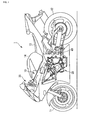
- Fig. 1 is an external side view of a motorcycle according to an embodiment of the present invention.
- a motorcycle 1 shown in the figure includes a body frame 10, a front wheel 11 that is a steered wheel, a rear wheel 12 that is a driving wheel, a seat 13 on which a rider sits, a fuel tank 14, handlebar 20, an engine 30, and a transmission mechanism 40.
- ATV all-terrain vehicle
- a three-wheeled or four-wheeled buggy a snowmobile.
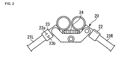
- Fig. 2 is a schematic view of the handlebars 20.
- a right grip 21 R on the handlebars 20 shown in the figure is an accelerator grip.
- a rider can adjust the degree of accelerator opening by twisting the right grip 21 R.
- An accelerator opening detector 22 attached to the right grip 21 R detects the degree of accelerator opening adjusted by the rider.
- a shift switch 23 attached to a left grip 21 L on the handlebars 20 serves as a shift command receiving unit.
- the shift switch 23 includes an upshift switch 23a and a downshift switch 23b. The rider can successively select a gear stage of the transmission mechanism 40 from neutral through to the top gear by manually operating the upshift switch 23a and the downshift switch 23b.
- the shift command receiving unit is not limited to the shift switch 23, and other input devices such as a shift pedal may be used.
- An indicator 24 is disposed at the center of the handlebars 20 so as to indicate the present gear stage.
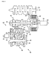
- the power that is input to the primary driven gear 41 is transmitted to a main shaft 43 through a clutch 42.
- a wet multiple disc clutch is shown in the figure, the clutch 42 is not limited to being of this type.
- Various known clutches such as a dry clutch and a single disc clutch may instead be used.
- Transmission gears 44 for multiple gear stages are disposed on the main shaft 43.
- the transmission gears 44 mesh with transmission gears 46 disposed on a drive shaft 45. Although the transmission gears 44 and 46 are separated in Fig. 3 , they mesh with each other in reality as described above.
- the power is transmitted from the main shaft 43 to the drive shaft 45 through only a selected pair of the transmission gears 44 and 46, while the remaining transmission gears 44 and 46 rotate freely.
- the pair of the transmission gears 44 and 46 that transmits the power is selected by rotating a shift cam 47 and thereby moving a shift fork 48.
- the main shaft 43, the transmission gears 44, the drive shaft 45, the transmission gears 46, the shift cam 47, and the shift fork 48 constitute a transmission 50, which is known as a dog clutch transmission.
- Fig. 4 is a diagram showing a structure of one of the transmission gears 44.
- the transmission gear 44 includes a first gear 44a with dogs 80 on its axial end face, and a second gear 44b with recesses 81 on its axial end face.
- the first gear 44a is fitted onto the main shaft 43 extending through a splined hole 82 such that the first gear 44a does not rotate relative to the main shaft 43 but can be moved in the axis direction of the main shaft 43.
- the second gear 44b is mounted on the main shaft 43 such that the second gear 44b can rotate freely.
- the first gear 44a can be moved in the axis direction using the shift fork 48.
- the dogs 80 on the first gear 44a do not mesh with the recesses 81 in the second gear 44b, the power that is input to the main shaft 43 is not transmitted to the second gear 44b, because the first gear 44a and the second gear 44b rotate freely relative to each other.
- the dogs 80 on the first gear 44a are inserted into the recesses 81 in the second gear 44b, the first gear 44a and the second gear 44b rotate together so that the power that is input to the main shaft 43 is transmitted to the drive shaft 45 through the second gear 44b and to the transmission gear 46 that meshes with the second gear 44b.
- the main shaft 43 and the drive shaft 45 are provided with respective transmission gears 44 and 46, each of which includes gears similar to the first gear 44a and the second gear 44b.
- the transmission 50 changes the reduction ratio at which the power is transmitted from the main shaft 43 to the drive shaft 45 by appropriately selecting a combination of the transmission gear 44 and the transmission gear 46 whose dogs 80 and recesses 81 mesh with each other.
- a dog insert operation When a dog insert operation is conducted, i.e. when the first gear 44a is moved in the axis direction to the second gear 44b, the dogs 80 may contact an axial end face 83 of the second gear 44b instead of contacting the recesses 81. In this case, if the first gear 44a and the second gear 44b rotate at the same speed, the shift operation is disabled, which is called a dog contact state.
- a torque should be applied to one of the first gear 44a and the second gear 44b so that the first and second gears rotate relative to each other in sliding contact.
- the torque can be provided to the first gear 44a through the main shaft 43 by conducting the dog insert operation and the disengagement operation of the clutch at specified timings so that the dogs are inserted while the clutch 42 is partially engaged.
- the power transmitted to the drive shaft 45 is transmitted to the rear wheel 12 through a well-known power transmission mechanism (not shown), such as a chain mechanism, a belt mechanism, or a shaft drive mechanism so as to drive the motorcycle 1.
- a well-known power transmission mechanism such as a chain mechanism, a belt mechanism, or a shaft drive mechanism so as to drive the motorcycle 1.
- the ratio between the rotation speed of the drive shaft 45 and the rear wheel 12, which is generated by the power transmission mechanism, is known as a secondary reduction ratio.
- a drive shaft tachometer 49 is attached to an end of the drive shaft 45.
- a clutch actuator 51 and a shift actuator 52 actuate the clutch 42 and the transmission 50, respectively.
- the clutch actuator 51 thrusts or retracts a rod 53 so as to disengage, engage, or partially engage the clutch 42.
- a clutch actuator position detector 54 for detecting a position of the clutch actuator is attached to the clutch actuator 51.
- the shift actuator 52 shifts up or down a gear in the transmission 50 by rotating a shift arm 55 and thereby rotating the shift cam 47 by a certain angle at a time.
- a potentiometer 56 for detecting a rotation angle of the shift actuator 52 is attached to the shift actuator 52.
- a gear position detector 57 for detecting the present gear position is attached to an end of the shift cam 47.
- a known electric motor such as a servomotor or a stepping motor, or a known actuator such as a hydraulic motor or a hydraulic cylinder may be used as the clutch actuator 51 and the shift actuator 52.
- the clutch actuator 51 is directly connected to the rod 53
- the shift actuator 52 is directly connected to the shift arm 55.
- the clutch actuator 51 and the rod 53, and the shift actuator and the shift arm 55 may be interconnected with a gear mechanism or a link mechanism as necessary.
- a rotary encoder, a linear encoder, etc. can be used as the clutch actuator position detector 54.
- a known sensor such as a potentiometer, an optoelectronic switch, or a proximity switch can be used as the gear position detector 57.
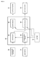
- Fig. 5 is a block diagram of a control system of the motorcycle 1.
- Sensors and switches 70, a main switch 71 that is linked to the key switch, a battery 72 for supplying power to a control device 60, the clutch actuator 51, and the shift actuator 52 are connected to the control device 60.
- the control device 60 includes a controller 61, a power supply circuit 62, and motor drivers 63 and 64.
- the controller 61 includes a known computer such as a digital signal processor (DSP) or a micro controller.
- DSP digital signal processor
- Various data that indicate states of various parts of the motorcycle 1 and commands issued by a rider are input from the sensors and switches 70 to the controller 61.
- the controller 61 controls the transmission mechanism 40 by sending signals to the motor drivers 63 and 64 and thereby actuating the clutch actuator 51 and the shift actuator 52.
- a program for operating the controller 61 is provided in non-volatile memory such as ROM or flash memory in the controller 61.
- the power supply circuit 62 which is linked to the main switch 71, adjusts voltage, current, etc., of electric power that is supplied from the battery 72 and supplies the electric power to the controller 61.
- the motor driver 63 receives the electric power from the battery 72 and actuates the clutch actuator 51 in accordance with a signal sent from the controller 61.
- the motor driver 64 actuates the shift actuator 52 likewise.
- Fig. 6 is a diagram showing a structure of the sensors and switches 70 connected to the control device 60.
- the sensors and switches 70 include the accelerator opening detector 22, the upshift switch 23a, the downshift switch 23b, the engine tachometer 33, the drive shaft tachometer 49, the clutch actuator position detector 54, the potentiometer 56, and the gear position detector 57. Data obtained from the sensors and switches 70 are input to the controller 61 as required.
- Fig. 7 is a flowchart showing an algorithm for control that is conducted by the control device 60 when a rider inputs a shift command while the motorcycle is running.
- the control device 60 detects that the rider pressed the upshift switch 23a or the downshift switch 23b and receives a shift command (step S0)
- a shift command to shift a gear to a nonexistent gear position such as a downshift command from the neutral position or an upshift command from the top gear, is rejected.
- the control device 60 determines the timing at which the shift command was issued and the state of the motorcycle 1 at that time.
- the control device 60 determines whether a shift operation is being conducted in the motorcycle 1 at that time (step S1) and whether an engagement operation of the clutch 42 is being conducted (step S10).
- the control device 60 determines whether a shift operation is being conducted in the motorcycle 1 at that time by checking a value of an internal flag stored in the control device 60.
- the value of the internal flag is set so as to indicate whether a shift operation is being conducted in the motorcycle 1.
- the control device 60 determines whether an engagement operation of the clutch 42 is being conducted by checking the content of the signal sent from the controller 61 to the motor driver 63.
- a determining unit for determining the timing at which the shift command was issued is implemented in software. Factors related to determining the timing of the shift command are not limited to the above-described items. For example, a time elapsed since the shift operation was started, or an operating state of the shift arm may be checked.
- step S3 the control device 60 reads a first schedule for conducting a disengagement operation of the clutch 42 and activating the transmission 50 from memory (not shown) such as ROM (step S3).
- the first schedule includes data such as timings at which the clutch 42 and the transmission 50 are to be activated, conditions for starting the operation, and speeds of the operation.
- step S4 the clutch 42 is disengaged and the transmission 50 is activated in accordance with the first schedule so as to shift up or down a gear.
- the clutch 42 is disengaged and the transmission 50 is activated in accordance with the first schedule so as to shift up or down a gear.
- Fig. 8 is a graph showing the clutch engagement map 90.
- the horizontal axis represents a difference in rotation speed between the input and output sides of the clutch 42, and the vertical axis represents a moving speed of the clutch actuator 51. For each gear position to be shifted to, the relationship between the difference in the rotation speeds and the moving speed of the clutch actuator is shown with a line.
- the control device 60 engages the clutch 42 by driving the clutch actuator 51 with the motor driver 63 on the basis of the moving speed of the clutch actuator 51 obtained from the clutch engagement map 90 in accordance with the difference in rotation speed between the input and output sides of the clutch 42 (step S6).
- the rotation speed of the input side of the clutch 42 is calculated by multiplying the primary reduction ratio and the output of the engine tachometer 33, which is data related to the rotation speed of the input side of the clutch 42.
- the rotation speed of the output side of the clutch 42 is calculated by multiplying the present gear ratio of the transmission 50 and the output data of the drive shaft tachometer 49 provided for detecting a vehicle speed, which is data related to the rotation speed of the output side of the clutch 42.
- the present gear ratio of the transmission 50 can be obtained by detecting a gear position with the gear position detector 57.
- a first shift operation according to the first schedule is conducted.
- the control device 60 serves as a shift control unit that conducts the disengagement and engagement operations of the clutch 42 and the shift operation including the dog insert operation of the transmission 50 in accordance with the shift command.
- control device 60 When the engagement of the clutch 42 is completed, the control device 60 returns the shift arm 55 to the neutral position (step S7), changes the value of the internal flag to a value indicating that a shift operation is not being conducted (step S8), and terminates the control for the shift operation (step S9).
- the area below the “disengaged position” in the graph shows a state in which the clutch 42 is disengaged
- the area above the “engaged position” shows a state in which the clutch 42 is engaged
- the area between these positions shows a state in which the clutch 42 is partially engaged.
- the shift arm position the “NEUTRAL” position in the graph shows a state in which the shift arm 55 is in the neutral position
- the "UPSHIFT” position shows a state in which the shift cam 47 is rotated by the shift arm 55 by a certain angle in the upshift direction
- the “DOWNSHIFT” position shows a state in which the shift cam 47 is rotated by the shift arm 55 by a certain angle in the downshift direction.
- the gear position shows a gear position of the transmission 50 corresponding to a rotation angle of the shift cam 47.
- Described below is a case in which a rider presses the downshift switch 23b while the motorcycle 1 is cruising in the fourth gear. Note that similar control is exercised when a rider presses the upshift switch 23a.
- the area denoted by A represents a state in which the motorcycle 1 is cruising.
- the shift switch 23 is not pressed, the clutch actuator 51 is in the engaged position, the shift arm 55 is in the neutral position, and the gear position is fourth.
- the control device 60 determines whether a shift operation is being conducted in the motorcycle 1. Since the motorcycle 1 is cruising in this case, the control device 60 determines that a shift operation is not being conducted. Then, following the above-described algorithm, the value of the internal flag is changed to a value indicating that a shift operation is being conducted, and a first schedule is read.
- the first schedule includes a timing and speed at which the clutch 42 is caused to start to move toward the disengaged position, and a timing and speed at which the shift arm 55 is caused to start to rotate in an upshift or a downshift direction.
- the clutch actuator 51 is caused to start to move as soon as the downshift switch 23b is pressed.
- the shift arm 55 starts to rotate (D in the graph) so as to start to rotate the shift cam 47 (E in the graph) and change the gear position of the transmission 50 from fourth to third.
- a pair of the transmission gears 44 and 46 in the transmission 50 that were meshed with each other to provide the fourth gear ratio become unmeshed.
- a pair of the transmission gears 44 and 46 in the transmission 50 become meshed with each other to provide the third gear ratio, when a dog insert operation is conducted so that the dogs 80 on either of the transmission gears 44 and 46 are inserted into the recesses 81 of the other one of the transmission gears 44 and 46.
- the length of the predetermined period C is set such that the dog insert operation is conducted while the clutch 42 is partially engaged.
- the control device 60 reads the clutch engagement map 90.
- the control device 60 reads output from the engine tachometer 33 and the drive shaft tachometer 49 as necessary, calculates the difference between the rotation speeds of the input and output sides of the clutch 42, and moves the clutch actuator 51 in accordance with the moving speed obtained from the clutch engagement map 90.
- the control device 60 When it is detected that the clutch actuator 51 is in an engaged position (I in the graph), the control device 60 returns the shift arm to the neutral position (J in the graph), changes the value of the internal flag to a value indicating that a shift operation is not being conducted, switches to a cruising mode, and terminates the shift operation.
- step S1 determines that a shift operation is being conducted in the motorcycle 1 is described.
- the control device 60 proceeds to step S10 so as to determine whether the clutch 42 is in an engagement operation.
- step S14 the control device 60 rejects and cancels a new shift command (step S14) and continues the present shift operation.
- a buzzer or a display in the indicator 24, for example may indicate to the rider that the shift command is canceled.
- the control device 60 proceeds to step S11 and determines whether to accept the shift command that is input during the shift operation.
- the control device 60 accepts the shift command so as to respond to the shift command quickly issued by the rider.
- the new shift command which is input at a timing at which the rider feels that the present shift operation has finished but in fact the control has not yet finished, is accepted instead of being canceled, thereby providing the rider with natural, comfortable, and a responsive driving sensation.
- the rider inputs a new shift command at a timing at which the present shift operation is not almost finished, it is likely that the shift command is an improper operation. A shift operation at such timing would damage a comfortable driving sensation. In such a case, the control device 60 rejects and cancels the new shift command (step S14).
- the timing can be determined by applying the condition that (1) the difference in rotation speed between the input and output sides of the clutch 42 is equal to or less than a predetermined value. This is because, if the difference in rotation speed between the input and output sides of the clutch 42 is equal to or less than a predetermined value of, for example, 100 rpm, the shift operation is almost finished.
- the following conditions may be added: (2) the clutch actuator position is situated closer to the engaged position than a set position, and (3) a predetermined period elapses while the conditions (1) and (2) are satisfied.
- the predetermined period may be set at, for example, 20 ms. Obviously, the predetermined value and the predetermined period may be appropriately set such that a comfortable driving sensation is provided.
- the program for the determination includes a determining unit that is implemented in software.
- the determining unit determines whether the difference in rotation speed between the input and output sides of the clutch 42 is less than a predetermined value on the basis of the data related to the rotation speeds of the input and output sides of the clutch 42.
- the control device 60 When the control device 60 determines to accept the shift command that is input during the shift operation, the control device 60 reads a second schedule for disengaging the clutch 42 and activating the transmission 50 from memory (not shown) such as ROM (step S12). As in the first schedule, the second schedule includes data such as timings at which the clutch 42 and the transmission 50 are to be activated, conditions for starting the operation, and speeds of the operation.
- step S13 the engagement operation of the clutch 42 is interrupted, and the clutch 42 and the transmission 50 are activated in accordance with the second schedule so as to shift up or down a gear.
- the second schedule differs form the first schedule in that, as described later, even when a new shift operation is started during the present shift operation, the dog insert operation of the transmission 50 is conducted while the clutch 42 is partially engaged by shifting up or down a gear while the clutch actuator 51 is moved toward the disengaged position.
- step S5 Subsequent steps are as described above.
- steps S12, S13, S5, and S6 described above the second shift operation according to the second schedule is conducted.
- Fig. 10 is a graph showing behavior of the motorcycle 1 in a first example of the second shift operation.
- lines in sections of the graph show, from top to bottom, an input to the shift switch 23, a position of the clutch actuator, a position of the shift arm, and a change of the gear position in the transmission 50.
- the horizontal axis represents time for all sections of the graph.
Landscapes
- Engineering & Computer Science (AREA)
- Mechanical Engineering (AREA)
- General Engineering & Computer Science (AREA)
- Transportation (AREA)
- Chemical & Material Sciences (AREA)
- Combustion & Propulsion (AREA)
- Automation & Control Theory (AREA)
- Control Of Transmission Device (AREA)
- Mechanical Operated Clutches (AREA)
- Hydraulic Clutches, Magnetic Clutches, Fluid Clutches, And Fluid Joints (AREA)
- Gear-Shifting Mechanisms (AREA)
Abstract
Description
- The present invention relates to a device and a method for controlling a transmission mechanism of a motor vehicle, and to a motor vehicle. In particular, the present invention relates to control exercised when engaging a clutch in a motor vehicle having a clutch and a dog clutch transmission actuated by respective actuators.
- A motor vehicle having a dog clutch transmission in which a clutch and a transmission are actuated by actuators such as motors has already become practically available. Such a motor vehicle is primarily characterized by automatically performing a series of shift operations including disengaging of the clutch, shifting of gears, and re-engaging of the clutch, when a rider only inputs a shift command.
- Japanese Unexamined Patent Application Publication No.
2006-170229 2006-170229 - In the motor vehicle disclosed in Japanese Unexamined Patent Application Publication No.
2006-170229 - The present invention has been achieved against such a background. An object of the present invention is to provide control that makes possible a shifting operation having good response by accepting an additional shift command during a shift operation of a motorcycle having a clutch and a dog clutch transmission actuated by actuators such as motors.
- In accordance with a first aspect, the present invention provides a device for controlling a transmission mechanism for a motor vehicle, the transmission mechanism including a transmission having a clutch, gears each having a dog, and gears each having a recess into which a dog is insertable, the clutch and the gears being actuated by respective actuators, wherein a shift operation is conducted by conducting a dog insert operation in which a specified one of the dogs is inserted into a specified one of the recesses, and the device includes a shift command receiving unit for receiving a shift command; a shift control unit for conducting disengagement and engagement operations of the clutch and the shift operation including the dog insert operation of the transmission in accordance with the shift command; and a shift command timing determining unit for determining timing at which the shift command was issued, wherein, when the shift command timing determining unit determines that the shift command was issued at a timing at which the shift operation was not being conducted, the shift control unit is arranged to conduct a first shift operation in which the disengagement operation of the clutch and the dog insert operation of the transmission are conducted in accordance with a first schedule and then the engagement operation of the clutch is conducted, and wherein, when the shift command timing determining unit determines that the shift command was issued at a timing at which the shift operation and the engagement operation of the clutch were being conducted, the shift control unit is arranged to interrupt the engagement operation of the clutch and conduct a second shift operation in which the disengagement operation of the clutch and the dog insert operation of the transmission are conducted in accordance with a second schedule that is different from the first schedule and then the engagement operation of the clutch is conducted.
- In accordance with a second aspect, the present invention provides a method for controlling a transmission mechanism of a motor vehicle, the transmission mechanism including a transmission having a clutch, gears each having a dog, and gears each having a recess into which a dog is insertable, the clutch and the gears being actuated by respective actuators, wherein a shift operation is conducted by inserting a specified one of the dogs into a specified one of the recesses, and the method includes a shift command receiving step for receiving a shift command; a shift control step for conducting disengagement and engagement operations of the clutch and the shift operation including the dog insert operation of the transmission in accordance with the shift command; and a shift command timing determining step for determining timing at which the shift command was issued, wherein, when it is determined at the shift command timing determining step that the shift command was issued at a timing at which the shift operation was not being conducted, a first shift operation in which the disengagement operation of the clutch and the dog insert operation of the transmission are conducted in accordance with a first schedule and then the engagement operation of the clutch is conducted in the shift control step, and wherein, when it is determined at the shift command timing determining step that the shift command was issued at a timing at which the shift operation and the engagement operation of the clutch were being conducted, the engagement operation of the clutch is interrupted and a second shift operation in which the disengagement operation of the clutch and the dog insert operation of the transmission are conducted in accordance with a second schedule that is different from the first schedule and then the engagement operation of the clutch is conducted in the shift control step.
- In accordance with a third aspect, the present invention provides a method for controlling a motor vehicle including a transmission mechanism including a transmission having a clutch, gears each having a dog, and gears each having a recess into which a dog is insertable, the clutch and the gears being actuated by respective actuators, wherein a shift operation is conducted by inserting a specified one of the dogs into a specified one of the recesses, and the method includes a shift command receiving step for receiving a shift command; a shift control step for conducting disengagement and engagement operations of the clutch and the shift operation including the dog insert operation of the transmission in accordance with the shift command; and a shift command timing determining step for determining timing at which the shift command was issued, wherein, when it is determined at the shift command timing determining step that the shift command was issued at a timing at which the shift operation was not being conducted, a first shift operation in which the disengagement operation of the clutch and the dog insert operation of the transmission are conducted in accordance with a first schedule and then the engagement operation of the clutch is conducted in the shift control step, and wherein, when it is determined at the shift command timing determining step that the shift command was issued at a timing at which the shift operation and the engagement operation of the clutch were being conducted, the engagement operation of the clutch is interrupted and a second shift operation in which the disengagement operation of the clutch and the dog insert operation of the transmission are conducted in accordance with a second schedule that is different from the first schedule and then the engagement operation of the clutch is conducted in the shift control step.
- In accordance with a fourth aspect, the present invention provides a vehicle including the device for controlling a transmission mechanism according to the first aspect of the present invention.
- With the device and the method for controlling the transmission mechanism and the method for controlling the motor vehicle, in a motor vehicle having a clutch and a dog clutch transmission actuated by an actuator such as a motor, an additional shift command can be accepted during a shift operation, thereby providing control that makes possible a responsive shift operation.
- Embodiments of the invention are described below, by way of example only, with reference to the drawings.
-
Fig. 1 is an external side view of a motorcycle according to an embodiment of the present invention. -
Fig. 2 is a block diagram of handlebars. -
Fig. 3 is a schematic view showing a structure of a transmission mechanism. -
Fig. 4 is a diagram showing a structure of a transmission gear. -
Fig. 5 is a block diagram of a control system. -
Fig. 6 is a diagram showing a structure of sensors and switches. -
Fig. 7 is a flowchart showing a control algorithm executed by a control device when a rider inputs a shift command while the motorcycle is running. -
Fig. 8 is a graph showing a clutch engagement map. -
Fig. 9 is a graph showing behavior of the motorcycle during a first shift operation. -
Fig. 10 is a graph showing behavior of the motorcycle in a first example of a second shift operation. -
Fig. 11 is a graph showing behavior of the motorcycle in a second example of a second shift operation. - While the invention is susceptible to various modifications and alternative forms, specific embodiments are shown by way of example in the drawings and are herein described in detail. It should be understood, however, that the drawings and detailed description are not intended to limit the invention to the particular form disclosed, but on the contrary, the invention is to cover all modifications, equivalents and alternatives falling within the spirit and scope of the present invention as defined in the appended claims.
- Hereinafter, embodiments according to the present invention are described in detail with reference to the drawings.
-
Fig. 1 is an external side view of a motorcycle according to an embodiment of the present invention. As in a well-known type of motorcycle, amotorcycle 1 shown in the figure includes abody frame 10, afront wheel 11 that is a steered wheel, arear wheel 12 that is a driving wheel, aseat 13 on which a rider sits, afuel tank 14,handlebar 20, anengine 30, and atransmission mechanism 40. Although the motorcycle is described here as an example of a motor vehicle, the present invention is applicable to various vehicles such as an all-terrain vehicle (ATV), a three-wheeled or four-wheeled buggy, and a snowmobile. -
Fig. 2 is a schematic view of thehandlebars 20. Aright grip 21 R on thehandlebars 20 shown in the figure is an accelerator grip. A rider can adjust the degree of accelerator opening by twisting the right grip 21 R. Anaccelerator opening detector 22 attached to theright grip 21 R detects the degree of accelerator opening adjusted by the rider. Ashift switch 23 attached to aleft grip 21 L on thehandlebars 20 serves as a shift command receiving unit. Theshift switch 23 includes anupshift switch 23a and adownshift switch 23b. The rider can successively select a gear stage of thetransmission mechanism 40 from neutral through to the top gear by manually operating theupshift switch 23a and thedownshift switch 23b. Note that the shift command receiving unit is not limited to theshift switch 23, and other input devices such as a shift pedal may be used. Anindicator 24 is disposed at the center of thehandlebars 20 so as to indicate the present gear stage. -
Fig. 3 is a schematic view showing a structure of thetransmission mechanism 40. Power generated by theengine 30 is transmitted through aprimary drive gear 32 on acrankshaft 31 to a primary drivengear 41 in thetransmission mechanism 40. Anengine tachometer 33 is attached to an end of thecrankshaft 31. A gear ratio of theprimary drive gear 32 to the primary drivengear 41 is called a primary reduction ratio. - The power that is input to the primary driven
gear 41 is transmitted to amain shaft 43 through aclutch 42. Although a wet multiple disc clutch is shown in the figure, theclutch 42 is not limited to being of this type. Various known clutches such as a dry clutch and a single disc clutch may instead be used.Transmission gears 44 for multiple gear stages are disposed on themain shaft 43. Thetransmission gears 44 mesh withtransmission gears 46 disposed on adrive shaft 45. Although thetransmission gears Fig. 3 , they mesh with each other in reality as described above. The power is transmitted from themain shaft 43 to thedrive shaft 45 through only a selected pair of thetransmission gears remaining transmission gears transmission gears shift cam 47 and thereby moving ashift fork 48. Themain shaft 43, thetransmission gears 44, thedrive shaft 45, thetransmission gears 46, theshift cam 47, and theshift fork 48 constitute atransmission 50, which is known as a dog clutch transmission. - Regarding gear shifting in the dog clutch transmission, it is known that a shift operation can be conducted more reliably when a dog insert operation and a clutch disengagement operation are conducted at specified timings for the reasons described below. Moreover, in order to reliably activate the clutch and the transmission at such timings, it is desirable that positions of the clutch and the transmission be definite when shift control starts. That is, since the positions of the clutch and transmission are indefinite during the shift operation, it is not desirable that the shift control start during the shift operation.
-
Fig. 4 is a diagram showing a structure of one of thetransmission gears 44. Thetransmission gear 44 includes afirst gear 44a withdogs 80 on its axial end face, and asecond gear 44b withrecesses 81 on its axial end face. Thefirst gear 44a is fitted onto themain shaft 43 extending through asplined hole 82 such that thefirst gear 44a does not rotate relative to themain shaft 43 but can be moved in the axis direction of themain shaft 43. On the other hand, thesecond gear 44b is mounted on themain shaft 43 such that thesecond gear 44b can rotate freely. - The
first gear 44a can be moved in the axis direction using theshift fork 48. When thedogs 80 on thefirst gear 44a do not mesh with therecesses 81 in thesecond gear 44b, the power that is input to themain shaft 43 is not transmitted to thesecond gear 44b, because thefirst gear 44a and thesecond gear 44b rotate freely relative to each other. When thedogs 80 on thefirst gear 44a are inserted into therecesses 81 in thesecond gear 44b, thefirst gear 44a and thesecond gear 44b rotate together so that the power that is input to themain shaft 43 is transmitted to thedrive shaft 45 through thesecond gear 44b and to thetransmission gear 46 that meshes with thesecond gear 44b. - The
main shaft 43 and thedrive shaft 45 are provided with respective transmission gears 44 and 46, each of which includes gears similar to thefirst gear 44a and thesecond gear 44b. Thetransmission 50 changes the reduction ratio at which the power is transmitted from themain shaft 43 to thedrive shaft 45 by appropriately selecting a combination of thetransmission gear 44 and thetransmission gear 46 whosedogs 80 and recesses 81 mesh with each other. - When a dog insert operation is conducted, i.e. when the
first gear 44a is moved in the axis direction to thesecond gear 44b, thedogs 80 may contact an axial end face 83 of thesecond gear 44b instead of contacting therecesses 81. In this case, if thefirst gear 44a and thesecond gear 44b rotate at the same speed, the shift operation is disabled, which is called a dog contact state. In order to prevent this state and reliably conduct the shift operation, a torque should be applied to one of thefirst gear 44a and thesecond gear 44b so that the first and second gears rotate relative to each other in sliding contact. Specifically, the torque can be provided to thefirst gear 44a through themain shaft 43 by conducting the dog insert operation and the disengagement operation of the clutch at specified timings so that the dogs are inserted while the clutch 42 is partially engaged. - The power transmitted to the
drive shaft 45 is transmitted to therear wheel 12 through a well-known power transmission mechanism (not shown), such as a chain mechanism, a belt mechanism, or a shaft drive mechanism so as to drive themotorcycle 1. The ratio between the rotation speed of thedrive shaft 45 and therear wheel 12, which is generated by the power transmission mechanism, is known as a secondary reduction ratio. Adrive shaft tachometer 49 is attached to an end of thedrive shaft 45. - In the
transmission mechanism 40 in this embodiment, aclutch actuator 51 and ashift actuator 52 actuate the clutch 42 and thetransmission 50, respectively. Theclutch actuator 51 thrusts or retracts arod 53 so as to disengage, engage, or partially engage the clutch 42. A clutchactuator position detector 54 for detecting a position of the clutch actuator is attached to theclutch actuator 51. Theshift actuator 52 shifts up or down a gear in thetransmission 50 by rotating ashift arm 55 and thereby rotating theshift cam 47 by a certain angle at a time. Apotentiometer 56 for detecting a rotation angle of theshift actuator 52 is attached to theshift actuator 52. Agear position detector 57 for detecting the present gear position is attached to an end of theshift cam 47. A known electric motor such as a servomotor or a stepping motor, or a known actuator such as a hydraulic motor or a hydraulic cylinder may be used as theclutch actuator 51 and theshift actuator 52. InFig. 3 , theclutch actuator 51 is directly connected to therod 53, and theshift actuator 52 is directly connected to theshift arm 55. However, theclutch actuator 51 and therod 53, and the shift actuator and theshift arm 55, may be interconnected with a gear mechanism or a link mechanism as necessary. A rotary encoder, a linear encoder, etc., can be used as the clutchactuator position detector 54. A known sensor such as a potentiometer, an optoelectronic switch, or a proximity switch can be used as thegear position detector 57. -
Fig. 5 is a block diagram of a control system of themotorcycle 1. Sensors and switches 70, amain switch 71 that is linked to the key switch, abattery 72 for supplying power to acontrol device 60, theclutch actuator 51, and theshift actuator 52 are connected to thecontrol device 60. - The
control device 60 includes acontroller 61, apower supply circuit 62, andmotor drivers controller 61 includes a known computer such as a digital signal processor (DSP) or a micro controller. Various data that indicate states of various parts of themotorcycle 1 and commands issued by a rider are input from the sensors and switches 70 to thecontroller 61. On the basis of the data, thecontroller 61 controls thetransmission mechanism 40 by sending signals to themotor drivers clutch actuator 51 and theshift actuator 52. A program for operating thecontroller 61 is provided in non-volatile memory such as ROM or flash memory in thecontroller 61. Thepower supply circuit 62, which is linked to themain switch 71, adjusts voltage, current, etc., of electric power that is supplied from thebattery 72 and supplies the electric power to thecontroller 61. Themotor driver 63 receives the electric power from thebattery 72 and actuates theclutch actuator 51 in accordance with a signal sent from thecontroller 61. Themotor driver 64 actuates theshift actuator 52 likewise. -
Fig. 6 is a diagram showing a structure of the sensors and switches 70 connected to thecontrol device 60. The sensors and switches 70 include theaccelerator opening detector 22, theupshift switch 23a, thedownshift switch 23b, theengine tachometer 33, thedrive shaft tachometer 49, the clutchactuator position detector 54, thepotentiometer 56, and thegear position detector 57. Data obtained from the sensors and switches 70 are input to thecontroller 61 as required. - Hereinafter, control for conducting a shift operation of the
motorcycle 1 having the above-described structure while themotorcycle 1 is running is described in detail. -
Fig. 7 is a flowchart showing an algorithm for control that is conducted by thecontrol device 60 when a rider inputs a shift command while the motorcycle is running. With reference to the flowchart, thecontrol device 60 detects that the rider pressed theupshift switch 23a or thedownshift switch 23b and receives a shift command (step S0) A shift command to shift a gear to a nonexistent gear position, such as a downshift command from the neutral position or an upshift command from the top gear, is rejected. Upon receiving the shift command, thecontrol device 60 determines the timing at which the shift command was issued and the state of themotorcycle 1 at that time. Specifically, thecontrol device 60 determines whether a shift operation is being conducted in themotorcycle 1 at that time (step S1) and whether an engagement operation of the clutch 42 is being conducted (step S10). Thecontrol device 60 determines whether a shift operation is being conducted in themotorcycle 1 at that time by checking a value of an internal flag stored in thecontrol device 60. The value of the internal flag is set so as to indicate whether a shift operation is being conducted in themotorcycle 1. Thecontrol device 60 determines whether an engagement operation of the clutch 42 is being conducted by checking the content of the signal sent from thecontroller 61 to themotor driver 63. In a program for making these checks, a determining unit for determining the timing at which the shift command was issued is implemented in software. Factors related to determining the timing of the shift command are not limited to the above-described items. For example, a time elapsed since the shift operation was started, or an operating state of the shift arm may be checked. - If a shift operation is not being conducted in the
motorcycle 1 at that time, thecontrol device 60 proceeds to step S2 and changes the value of the internal flag to a value indicating that a shift operation is being conducted. Then, thecontrol device 60 reads a first schedule for conducting a disengagement operation of the clutch 42 and activating thetransmission 50 from memory (not shown) such as ROM (step S3). The first schedule includes data such as timings at which the clutch 42 and thetransmission 50 are to be activated, conditions for starting the operation, and speeds of the operation. - In step S4, the clutch 42 is disengaged and the
transmission 50 is activated in accordance with the first schedule so as to shift up or down a gear. At this time, because a gear is shifted up or down while the clutch 42 is being moved to the disengaged position as described below, the dog insert operation in thetransmission 50 is conducted while the clutch 42 is partially engaged. - When the clutch 42 is disengaged and the dog insert operation in the
transmission 50 is completed, thecontrol device 60 reads aclutch engagement map 90 from memory (not shown) such as ROM (step S5).Fig. 8 is a graph showing theclutch engagement map 90. The horizontal axis represents a difference in rotation speed between the input and output sides of the clutch 42, and the vertical axis represents a moving speed of theclutch actuator 51. For each gear position to be shifted to, the relationship between the difference in the rotation speeds and the moving speed of the clutch actuator is shown with a line. - The
control device 60 engages the clutch 42 by driving theclutch actuator 51 with themotor driver 63 on the basis of the moving speed of theclutch actuator 51 obtained from theclutch engagement map 90 in accordance with the difference in rotation speed between the input and output sides of the clutch 42 (step S6). The rotation speed of the input side of the clutch 42 is calculated by multiplying the primary reduction ratio and the output of theengine tachometer 33, which is data related to the rotation speed of the input side of the clutch 42. The rotation speed of the output side of the clutch 42 is calculated by multiplying the present gear ratio of thetransmission 50 and the output data of thedrive shaft tachometer 49 provided for detecting a vehicle speed, which is data related to the rotation speed of the output side of the clutch 42. The present gear ratio of thetransmission 50 can be obtained by detecting a gear position with thegear position detector 57. - In the above-described steps S3 to S6, a first shift operation according to the first schedule is conducted. During the first shift operation, the
control device 60 serves as a shift control unit that conducts the disengagement and engagement operations of the clutch 42 and the shift operation including the dog insert operation of thetransmission 50 in accordance with the shift command. - When the engagement of the clutch 42 is completed, the
control device 60 returns theshift arm 55 to the neutral position (step S7), changes the value of the internal flag to a value indicating that a shift operation is not being conducted (step S8), and terminates the control for the shift operation (step S9). -
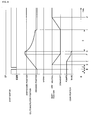
Fig. 9 is a graph showing behavior of themotorcycle 1 during the first shift operation. Lines in sections of the graph show, from top to bottom, an input to theshift switch 23, a position of the clutch actuator, a position of the shift arm, and a change of the gear position in thetransmission 50. The horizontal axis represents time for all sections of the graph. Regarding the input to theshift switch 23, the middle position in the graph shows a state in which there is no input, the "UP" position shows a state in which theupshift switch 23a is pressed, and the "DOWN" position shows a state in which thedownshift switch 23b is pressed. Regarding the clutch actuator position, the area below the "disengaged position" in the graph shows a state in which the clutch 42 is disengaged, the area above the "engaged position" shows a state in which the clutch 42 is engaged, and the area between these positions shows a state in which the clutch 42 is partially engaged. Regarding the shift arm position, the "NEUTRAL" position in the graph shows a state in which theshift arm 55 is in the neutral position, the "UPSHIFT" position shows a state in which theshift cam 47 is rotated by theshift arm 55 by a certain angle in the upshift direction, the "DOWNSHIFT" position shows a state in which theshift cam 47 is rotated by theshift arm 55 by a certain angle in the downshift direction. Lastly, the gear position shows a gear position of thetransmission 50 corresponding to a rotation angle of theshift cam 47. - Described below is a case in which a rider presses the
downshift switch 23b while themotorcycle 1 is cruising in the fourth gear. Note that similar control is exercised when a rider presses theupshift switch 23a. - In the graph, the area denoted by A represents a state in which the
motorcycle 1 is cruising. At this time, as shown in the graph, theshift switch 23 is not pressed, theclutch actuator 51 is in the engaged position, theshift arm 55 is in the neutral position, and the gear position is fourth. When a rider presses thedownshift switch 23b (B in the graph), thecontrol device 60 determines whether a shift operation is being conducted in themotorcycle 1. Since themotorcycle 1 is cruising in this case, thecontrol device 60 determines that a shift operation is not being conducted. Then, following the above-described algorithm, the value of the internal flag is changed to a value indicating that a shift operation is being conducted, and a first schedule is read. - The first schedule includes a timing and speed at which the clutch 42 is caused to start to move toward the disengaged position, and a timing and speed at which the
shift arm 55 is caused to start to rotate in an upshift or a downshift direction. As shown in the graph, theclutch actuator 51 is caused to start to move as soon as thedownshift switch 23b is pressed. Then, after a predetermined period denoted by C in the graph, theshift arm 55 starts to rotate (D in the graph) so as to start to rotate the shift cam 47 (E in the graph) and change the gear position of thetransmission 50 from fourth to third. At this time, a pair of the transmission gears 44 and 46 in thetransmission 50 that were meshed with each other to provide the fourth gear ratio become unmeshed. Subsequently, a pair of the transmission gears 44 and 46 in thetransmission 50 become meshed with each other to provide the third gear ratio, when a dog insert operation is conducted so that thedogs 80 on either of the transmission gears 44 and 46 are inserted into therecesses 81 of the other one of the transmission gears 44 and 46. The length of the predetermined period C is set such that the dog insert operation is conducted while the clutch 42 is partially engaged. - When the clutch
actuator position detector 54 detects that theclutch actuator 51 has reached the disengaged position (F in the graph), and thegear position detector 57 detects that the gear position has been changed to third (G in the graph), thecontrol device 60 reads theclutch engagement map 90. - In the area denoted by H, the
control device 60 reads output from theengine tachometer 33 and thedrive shaft tachometer 49 as necessary, calculates the difference between the rotation speeds of the input and output sides of the clutch 42, and moves theclutch actuator 51 in accordance with the moving speed obtained from theclutch engagement map 90. - When it is detected that the
clutch actuator 51 is in an engaged position (I in the graph), thecontrol device 60 returns the shift arm to the neutral position (J in the graph), changes the value of the internal flag to a value indicating that a shift operation is not being conducted, switches to a cruising mode, and terminates the shift operation. - Referring back to
Fig. 7 , a case when step S1 determines that a shift operation is being conducted in themotorcycle 1 is described. When the internal flag indicates that a shift operation is being conducted in themotorcycle 1, thecontrol device 60 proceeds to step S10 so as to determine whether the clutch 42 is in an engagement operation. - If the clutch 42 is not in an engagement operation, the
control device 60 rejects and cancels a new shift command (step S14) and continues the present shift operation. In this case, a buzzer or a display in theindicator 24, for example, may indicate to the rider that the shift command is canceled. If the clutch 42 is in an engagement operation, thecontrol device 60 proceeds to step S11 and determines whether to accept the shift command that is input during the shift operation. - If the rider inputs a new shift command at a timing at which the present shift operation has been almost finished, the
control device 60 accepts the shift command so as to respond to the shift command quickly issued by the rider. By doing so, the new shift command, which is input at a timing at which the rider feels that the present shift operation has finished but in fact the control has not yet finished, is accepted instead of being canceled, thereby providing the rider with natural, comfortable, and a responsive driving sensation. On the other hand, if the rider inputs a new shift command at a timing at which the present shift operation is not almost finished, it is likely that the shift command is an improper operation. A shift operation at such timing would damage a comfortable driving sensation. In such a case, thecontrol device 60 rejects and cancels the new shift command (step S14). - Specifically, the timing can be determined by applying the condition that (1) the difference in rotation speed between the input and output sides of the clutch 42 is equal to or less than a predetermined value. This is because, if the difference in rotation speed between the input and output sides of the clutch 42 is equal to or less than a predetermined value of, for example, 100 rpm, the shift operation is almost finished. Moreover, the following conditions may be added: (2) the clutch actuator position is situated closer to the engaged position than a set position, and (3) a predetermined period elapses while the conditions (1) and (2) are satisfied. The predetermined period may be set at, for example, 20 ms. Obviously, the predetermined value and the predetermined period may be appropriately set such that a comfortable driving sensation is provided. The program for the determination includes a determining unit that is implemented in software. The determining unit determines whether the difference in rotation speed between the input and output sides of the clutch 42 is less than a predetermined value on the basis of the data related to the rotation speeds of the input and output sides of the clutch 42.
- When the
control device 60 determines to accept the shift command that is input during the shift operation, thecontrol device 60 reads a second schedule for disengaging the clutch 42 and activating thetransmission 50 from memory (not shown) such as ROM (step S12). As in the first schedule, the second schedule includes data such as timings at which the clutch 42 and thetransmission 50 are to be activated, conditions for starting the operation, and speeds of the operation. - In step S13, the engagement operation of the clutch 42 is interrupted, and the clutch 42 and the
transmission 50 are activated in accordance with the second schedule so as to shift up or down a gear. The second schedule differs form the first schedule in that, as described later, even when a new shift operation is started during the present shift operation, the dog insert operation of thetransmission 50 is conducted while the clutch 42 is partially engaged by shifting up or down a gear while theclutch actuator 51 is moved toward the disengaged position. - When the clutch 42 is disengaged and the dog insert operation of the
transmission 50 is finished, the flow proceeds to step S5. Subsequent steps are as described above. On the basis of steps S12, S13, S5, and S6 described above, the second shift operation according to the second schedule is conducted. - The second shift operation is conducted, not only when a new shift command is input during the first shift operation, but also when a new shift command is input during the second shift operation.
-
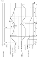
Fig. 10 is a graph showing behavior of themotorcycle 1 in a first example of the second shift operation. As inFig. 9 , lines in sections of the graph show, from top to bottom, an input to theshift switch 23, a position of the clutch actuator, a position of the shift arm, and a change of the gear position in thetransmission 50. The horizontal axis represents time for all sections of the graph. - A case in which a rider pressed the
downshift switch 23b during the first shift operation described above with reference toFig. 9 is described here. The parts denoted by A to G in the graph are the same as described before. The area denoted by H' in the graph represents that thecontrol device 60 performs control so as to move and engage theclutch actuator 51 on the basis of theclutch engagement map 90. - When the
downshift switch 23b is pressed again (K in the graph), thecontrol device 60 determines whether to accept the shift command that is input during the present shift operation. In this case, because the difference in speed between the input and output sides of the clutch 42 is equal to or less than a predetermined value (100 rpm), the shift command is accepted and the second schedule is read. - The second schedule includes timing and speed at which the
shift arm 55 is caused to start to rotate toward the neutral position, timing and speed at which theclutch actuator 51 is caused to start to move toward the disengaged position, and timing and speed at which theshift arm 55 is caused to start to rotate in the upshift or downshift direction. As shown in the figure, at the position shown by K in the graph, theshift arm 55 is in the downshift position. In the second schedule, theshift arm 55 is first caused to start to move toward the neutral position, while the clutch actuator position is maintained (numeral 100 in the graph). After a predetermined period L in the graph, theclutch actuator 51 starts to move in a disengagement direction (M in the graph). After a predetermined period N, theshift arm 55 starts rotating (O in the figure), thereby rotating the shift cam 47 (P in the figure) and changing the reduction ratio of thetransmission 50 from third to second. By delaying the movement of theclutch actuator 51 in the disengagement direction by the predetermined period L as shown in the graph, the dog insert operation is conducted while the clutch 42 is partially engaged, and in particular, while the clutch 42 is moving in the disengagement direction in a partially engaged state. The predetermined periods L and N may be set appropriately such that the dog insert operation is conducted reliably. - Then, when the clutch
actuator position detector 54 detects that theclutch actuator 51 has reached the disengaged position (Q in the graph) and thegear position detector 57 detects that the gear position has been changed to second (R in the graph), thecontrol device 60 reads theclutch engagement map 90 and moves theclutch actuator 51 in accordance with the map (area S in the graph). - When it is detected that the
clutch actuator 51 has reached the engaged position (T in the graph), thecontrol device 60 returns the shift arm to the neutral position (U in the graph), changes the value of the internal flag to a value indicating that a shift operation is not being conducted, and switches to a cruising mode, and terminates the shift operation. - In the above description, the movement of the
clutch actuator 51 in the disengagement direction was delayed by the predetermined period L. Alternatively, the movement of theclutch actuator 51 in the disengagement direction may be delayed until it is detected that theshift arm 55 has reached a predetermined position. That is, the clutch actuator position may be maintained at the present position until the shift arm reaches the point V in the graph. The position of theshift arm 55 can be obtained from the output value of thepotentiometer 56 attached to theshift actuator 52. - A method for delaying the movement of the
clutch actuator 51 in the disengagement direction is not limited to the method of maintaining the clutch actuator position. Alternatively, as shown by numeral 101 in the graph, theclutch actuator 51 may be moved to a predetermined position after accepting the shift command, and then moved in the disengagement direction after a predetermined period. As a further alternative, as shown by numeral 102 in the graph, the dog insert operation may be conducted while the clutch 42 is moved in the disengagement direction in a partially engaged state by moving theclutch actuator 51 slower than in the first schedule. -
Fig. 11 is a graph showing behavior of themotorcycle 1 in a second example of the second shift operation. As inFigs. 9 and10 , lines in sections of the graph show, from top to bottom, an input to theshift switch 23, a position of the clutch actuator, a position of the shift arm, and a change of the gear position in thetransmission 50. The horizontal axis represents time for all the sections. In the following description, like numerals denote like parts in the above-described first example (Fig. 10 ). Overlapping descriptions are omitted. - This example differs from the first example in that, when it is detected that the gear position has been changed to third at time G in the graph, the shift arm is immediately controlled and returned to the neutral position. Therefore, by the time when the
control device 60 accepts an additional shift command during the first shift operation at time K in the graph, theshift arm 55 is already returned to the neutral position. - In the second schedule in this example, the
clutch actuator 51 is immediately caused to start to move, because it is not necessary that a movement of theclutch actuator 51 in the disengagement direction be delayed so as to wait until theshift arm 55 returns to the neutral position as in the first example. Then, since theclutch actuator 51 starts to move the clutch 42 from the partially engaged position toward the disengaged position, the disengagement operation by theclutch actuator 51 is conducted earlier than in the first schedule in which the clutch 42 is caused to start to move from the engaged position toward the disengaged position. - Therefore, a predetermined period W from time K in the graph to time O at which the
shift arm 55 begins to rotate is shorter than the predetermined period C in the first schedule. That is, the dog insert operation in thetransmission 50 in the second schedule is started earlier than the dog insert operation of thetransmission 50 in the first schedule. The length of the predetermined period W may be appropriately set such that the dog insert operation is conducted reliably. Alternatively, the length of W may be set in accordance with the output value of the clutchactuator position detector 54 that detects the position of theclutch actuator 51 at time K. That is, the nearer the position of theclutch actuator 51 at time K is to the disengaged position, the shorter is the predetermined period W; the nearer the position of theclutch actuator 51 at time K is to the engaged position, the longer is the predetermined period W. - The
shift cam 47 starts rotating with the rotation and the movement of the shift arm 55 (P in the graph) so that the gear ratio of thetransmission 50 is changed from third to second. When the clutchactuator position detector 54 detects that theclutch actuator 51 has reached the disengaged position (Q in the graph) and thegear position detector 57 detects that the gear position is changed to second (R in the graph), thecontrol device 60 moves theshift arm 55 to the neutral position and reads theclutch engagement map 90. According to theclutch engagement map 90, thecontrol device 60 moves the clutch actuator 51 (area S in the graph). - When it is detected that the
clutch actuator 51 is at the engaged position (T in the graph), thecontrol device 60 changes the internal flag to a value indicating that a shift operation is not being conducted, switches to the cruising mode, and terminates the shift operation. - Although it is assumed in the above description that a rider manually issues a shift command, a computer such as the
control device 60 may issue a shift command by automatic control. - As heretofore described, with the control device and method for the transmission mechanism of the motor vehicle and the motor vehicle according to the present invention, in the motor vehicle equipped with a clutch actuated by an actuator such as a motor and a dog clutch transmission, an additional shift command can be accepted during a shift operation, thereby enabling control for a responsive shift operation.
- 1: motorcycle, 10: body frame, 11: front wheel, 12: rear wheel, 13: seat, 14: fuel tank, 20: handlebar, 21 R: right grip, 21 L: left grip, 22: accelerator opening detector, 23: shift switch, 23a: upshift switch, 23b: downshift switch, 24: indicator, 30: engine, 31: crankshaft, 32: primary drive gear, 33: engine tachometer, 40: transmission mechanism, 41: primary driven gear, 42: clutch, 43: main shaft, 44: transmission gears, 45: drive shaft, 46: transmission gears, 47: shift cam, 48: shift fork, 49: drive shaft tachometer, 50: transmission, 51: clutch actuator, 52: shift actuator, 53: rod, 54: clutch actuator position detector, 55: shift arm, 56: potentiometer, 57: gear position detector, 60: control device, 61: controller, 62: power supply circuit, 63, 64: motor driver, 70: sensors and switches, 71: main switch, 72: battery, 80: dogs, 81: recesses, 82: splined hole, 83: axial end face, 90: clutch engagement map
Claims (12)
- A device for controlling a transmission mechanism of a motor vehicle, the transmission mechanism including a transmission having a clutch, gears each having a dog, and gears each having a recess into which a dog is insertable, the clutch and the gears being actuated by respective actuators, wherein a shift operation is conducted by conducting a dog insert operation in which a specified one of the dogs is inserted into a specified one of the recesses, the device comprising:a shift command receiving unit for receiving a shift command;a shift control unit for conducting disengagement and engagement operations of the clutch and the shift operation including the dog insert operation of the transmission in accordance with the shift command; anda shift command timing determining unit for determining timing at which the shift command was issued,wherein, when the shift command timing determining unit determines that the shift command was issued at a timing at which the shift operation was not being conducted, the shift control unit is arranged to conduct a first shift operation in which the disengagement operation of the clutch and the dog insert operation of the transmission are conducted in accordance with a first schedule and then the engagement operation of the clutch is conducted, and
wherein, when the shift command timing determining unit determines that the shift command was issued at a timing at which the shift operation and the engagement operation of the clutch were being conducted, the shift control unit is arranged to interrupt the engagement operation of the clutch and conduct a second shift operation in which the disengagement operation of the clutch and the dog insert operation of the transmission are conducted in accordance with a second schedule that is different from the first schedule and then the engagement operation of the clutch is conducted. - The device for controlling a transmission mechanism according to Claim 1, the device further comprising
a rotation speed difference determining unit for determining whether a difference in rotation speed between input and output sides of the clutch is less than a predetermined value on the basis of data related to the rotation speeds of the input and output sides of the clutch,
wherein the shift control unit is arranged to conduct the second shift operation when the rotation speed difference determining unit determines that the difference in rotation speed between the input and output sides of the clutch is less than the predetermined value. - The device for controlling a transmission mechanism according to Claim 1 or 2,
wherein the second schedule prescribes that the disengagement operation of the clutch is started after a lapse of a specified period. - The device for controlling a transmission mechanism according to Claim 1 or 2,
wherein the second schedule prescribes that the disengagement operation of the clutch is started after the clutch is moved to a specified position and a subsequent lapse of a specified period. - The device for controlling a transmission mechanism according to Claim 3 or 4,
wherein the specified period in the second schedule is determined in advance. - The device for controlling a transmission mechanism according to Claim 3 or 4, the device further comprising
a detection unit for detecting a position of the actuator that actuates the transmission,
wherein the specified period in the second schedule elapses when the detection unit detects that the actuator is in a specified position. - The device for controlling a transmission mechanism according to any one of Claims 1 to 6,
wherein the second schedule prescribes that the disengagement operation of the clutch is conducted at a speed lower than a speed of the disengagement operation of the clutch prescribed in the first schedule. - The device for controlling a transmission mechanism according to any one of Claims 1 to 7,
wherein the dog insert operation of the transmission according to the second schedule is started earlier than the dog insert operation of the transmission according to the first schedule. - The device for controlling a transmission mechanism according to any one of Claims 1 to 8, wherein the shift command is input by a rider.
- A vehicle including the device for controlling a transmission mechanism according to any one of Claims 1 to 9.
- A method for controlling a transmission mechanism of a motor vehicle, the transmission mechanism including a transmission having a clutch, gears each having a dog, and gears each having a recess into which a dog is insertable, the clutch and the gears being actuated by respective actuators, wherein a shift operation is conducted by inserting a specified one of the dogs into a specified one of the recesses, the method comprising:a shift command receiving step for receiving a shift command;a shift control step for conducting disengagement and engagement operations of the clutch and the shift operation including the dog insert operation of the transmission in accordance with the shift command; anda shift command timing determining step for determining timing at which the shift command was issued,wherein, when it is determined at the shift command timing determining step that the shift command was issued at a timing at which the shift operation was not being conducted, a first shift operation, in which the disengagement operation of the clutch and the dog insert operation of the transmission are conducted in accordance with a first schedule and then the engagement operation of the clutch is conducted, is conducted in the shift control step, and
wherein, when it is determined at the shift command timing determining step that the shift command was issued at a timing at which the shift operation and the engagement operation of the clutch were being conducted, the engagement operation of the clutch is interrupted and a second shift operation, in which the disengagement operation of the clutch and the dog insert operation of the transmission are conducted in accordance with a second schedule that is different from the first schedule and then the engagement operation of the clutch is conducted, is conducted in the shift control step. - A method for controlling a motor vehicle having a transmission mechanism including a transmission having a clutch, gears each having a dog, and gears each having a recess into which a dog is insertable, the clutch and the gears being actuated by respective actuators, wherein a shift operation is conducted by inserting a specified one of the dogs into a specified one of the recesses, the method comprising:a shift command receiving step for receiving a shift command;a shift control step for conducting disengagement and engagement operations of the clutch and the shift operation including the dog insert operation of the transmission in accordance with the shift command; anda shift command timing determining step for determining timing at which the shift command was issued,wherein, when it is determined at the shift command timing determining step that the shift command was issued at a timing at which the shift operation was not being conducted, a first shift operation, in which the disengagement operation of the clutch and the dog insert operation of the transmission are conducted in accordance with a first schedule and then the engagement operation of the clutch is conducted, is conducted in the shift control step, and
wherein, when it is determined at the shift command timing determining step that the shift command was issued at a timing at which the shift operation and the engagement operation of the clutch were being conducted, the engagement operation of the clutch is interrupted and a second shift operation, in which the disengagement operation of the clutch and the dog insert operation of the transmission are conducted in accordance with a second schedule that is different from the first schedule and then the engagement operation of the clutch is conducted, is conducted in the shift control step.
Applications Claiming Priority (1)
| Application Number | Priority Date | Filing Date | Title |
|---|---|---|---|
| JP2008132191A JP5058068B2 (en) | 2008-05-20 | 2008-05-20 | Control device for transmission mechanism, control method, and control method for vehicle with motor |
Publications (3)
| Publication Number | Publication Date |
|---|---|
| EP2123530A2 true EP2123530A2 (en) | 2009-11-25 |
| EP2123530A3 EP2123530A3 (en) | 2011-11-23 |
| EP2123530B1 EP2123530B1 (en) | 2012-08-29 |
Family
ID=41010562
Family Applications (1)
| Application Number | Title | Priority Date | Filing Date |
|---|---|---|---|
| EP09251317A Active EP2123530B1 (en) | 2008-05-20 | 2009-05-14 | Device and method for controlling transmission mechanism, and method for controlling motor vehicle |
Country Status (4)
| Country | Link |
|---|---|
| US (1) | US8090510B2 (en) |
| EP (1) | EP2123530B1 (en) |
| JP (1) | JP5058068B2 (en) |
| ES (1) | ES2390576T3 (en) |
Cited By (7)
| Publication number | Priority date | Publication date | Assignee | Title |
|---|---|---|---|---|
| EP2696109A1 (en) * | 2012-08-10 | 2014-02-12 | Yamaha Hatsudoki Kabushiki Kaisha | Automatic transmission device and vehicle including the same |
| US20160003353A1 (en) * | 2013-03-13 | 2016-01-07 | Nissan Motor Co., Ltd. | Automatic transmission control device |
| EP2982553A1 (en) * | 2014-08-08 | 2016-02-10 | Honda Motor Co., Ltd. | Braking force control apparatus for saddle ride-type vehicle |
| EP2975301A4 (en) * | 2013-03-13 | 2016-06-15 | Nissan Motor | Automatic transmission control device |
| EP3059475A1 (en) * | 2015-02-12 | 2016-08-24 | Toyota Jidosha Kabushiki Kaisha | Control device for vehicle |
| EP2949970A4 (en) * | 2013-01-22 | 2017-08-16 | Yamaha Hatsudoki Kabushiki Kaisha | Control unit, vehicle equipped with control unit, and control program |
| CN109383498A (en) * | 2017-08-08 | 2019-02-26 | 福特全球技术公司 | For controlling the softdog of vehicle drive assist system |
Families Citing this family (4)
| Publication number | Priority date | Publication date | Assignee | Title |
|---|---|---|---|---|
| JP5718706B2 (en) * | 2011-04-01 | 2015-05-13 | 本田技研工業株式会社 | In-vehicle power unit shift control device |
| JP6108985B2 (en) * | 2013-06-28 | 2017-04-05 | 株式会社ケーヒン | Shift operation detection unit |
| JP6487887B2 (en) * | 2016-09-28 | 2019-03-20 | 本田技研工業株式会社 | Power transmission device |
| JP6757371B2 (en) * | 2018-07-27 | 2020-09-16 | 本田技研工業株式会社 | Engine starter |
Citations (1)
| Publication number | Priority date | Publication date | Assignee | Title |
|---|---|---|---|---|
| JP2006170229A (en) | 2004-12-10 | 2006-06-29 | Yamaha Motor Co Ltd | Saddle-type vehicle shift control device, control method, and saddle-type vehicle |
Family Cites Families (7)
| Publication number | Priority date | Publication date | Assignee | Title |
|---|---|---|---|---|
| JPH07119814A (en) | 1993-10-25 | 1995-05-12 | Mitsubishi Motors Corp | Shift control device for automatic transmission |
| US5816100A (en) | 1996-09-17 | 1998-10-06 | Eaton Corporation | Skip shift selection control system and method |
| US6679133B1 (en) * | 1998-12-03 | 2004-01-20 | Hitachi, Ltd. | Gear-type automatic transmission and car using the gear type automatic transmission |
| JP4608298B2 (en) * | 2004-12-10 | 2011-01-12 | ヤマハ発動機株式会社 | Shift control device, shift control method, and saddle riding type vehicle |
| JP5164337B2 (en) * | 2006-04-18 | 2013-03-21 | ヤマハ発動機株式会社 | Automatic transmission control device and saddle riding type vehicle |
| JP5161644B2 (en) * | 2008-04-25 | 2013-03-13 | ヤマハ発動機株式会社 | Shift control device, straddle-type vehicle, and shift control method |
| US8439804B2 (en) * | 2008-10-28 | 2013-05-14 | Allison Transmission, Inc. | Electro-hydraulic control including blocking features for multi-speed automatic transmission |
-
2008
- 2008-05-20 JP JP2008132191A patent/JP5058068B2/en active Active
-
2009
- 2009-04-15 US US12/424,337 patent/US8090510B2/en active Active
- 2009-05-14 ES ES09251317T patent/ES2390576T3/en active Active
- 2009-05-14 EP EP09251317A patent/EP2123530B1/en active Active
Patent Citations (1)
| Publication number | Priority date | Publication date | Assignee | Title |
|---|---|---|---|---|
| JP2006170229A (en) | 2004-12-10 | 2006-06-29 | Yamaha Motor Co Ltd | Saddle-type vehicle shift control device, control method, and saddle-type vehicle |
Cited By (9)
| Publication number | Priority date | Publication date | Assignee | Title |
|---|---|---|---|---|
| EP2696109A1 (en) * | 2012-08-10 | 2014-02-12 | Yamaha Hatsudoki Kabushiki Kaisha | Automatic transmission device and vehicle including the same |
| EP2949970A4 (en) * | 2013-01-22 | 2017-08-16 | Yamaha Hatsudoki Kabushiki Kaisha | Control unit, vehicle equipped with control unit, and control program |
| US20160003353A1 (en) * | 2013-03-13 | 2016-01-07 | Nissan Motor Co., Ltd. | Automatic transmission control device |
| EP2975301A4 (en) * | 2013-03-13 | 2016-06-15 | Nissan Motor | Automatic transmission control device |
| US9874278B2 (en) * | 2013-03-13 | 2018-01-23 | Nissan Motor Co., Ltd. | Automatic transmission control device |
| EP2982553A1 (en) * | 2014-08-08 | 2016-02-10 | Honda Motor Co., Ltd. | Braking force control apparatus for saddle ride-type vehicle |
| EP3059475A1 (en) * | 2015-02-12 | 2016-08-24 | Toyota Jidosha Kabushiki Kaisha | Control device for vehicle |
| CN105888859A (en) * | 2015-02-12 | 2016-08-24 | 丰田自动车株式会社 | Control device for vehicle |
| CN109383498A (en) * | 2017-08-08 | 2019-02-26 | 福特全球技术公司 | For controlling the softdog of vehicle drive assist system |
Also Published As
| Publication number | Publication date |
|---|---|
| US8090510B2 (en) | 2012-01-03 |
| EP2123530B1 (en) | 2012-08-29 |
| ES2390576T3 (en) | 2012-11-14 |
| JP5058068B2 (en) | 2012-10-24 |
| JP2009281439A (en) | 2009-12-03 |
| US20090292429A1 (en) | 2009-11-26 |
| EP2123530A3 (en) | 2011-11-23 |
Similar Documents
| Publication | Publication Date | Title |
|---|---|---|
| EP2123530B1 (en) | Device and method for controlling transmission mechanism, and method for controlling motor vehicle | |
| US8177684B2 (en) | Gear change control device and method | |
| JP5711820B2 (en) | Electric vehicle | |
| JP5711821B2 (en) | Electric vehicle | |
| JP6049772B2 (en) | Transmission control device for motorcycle | |
| JP5656810B2 (en) | Shift control device for motorcycle | |
| EP3800381B1 (en) | Quickshifter-equipped vehicle control unit and quickshifter-equipped motorcycle | |
| JP2006170225A (en) | Clutch connection control device, clutch connection control method, and saddle riding type vehicle | |
| JP5116009B2 (en) | Shift control device for motorcycle | |
| EP2299095B1 (en) | Engine control system for a vehicle | |
| EP2112393B1 (en) | Control device and control method for transmission mechanism, and control method for vehicle with engine | |
| JP5247313B2 (en) | Control system and vehicle | |
| EP1854688A2 (en) | Straddle-type vehicle | |
| JP2010090928A (en) | Transmission control system and vehicle | |
| JP2019085894A (en) | Vehicle with automatic downshift function | |
| JP5124398B2 (en) | Torque estimation system and vehicle | |
| JP5107184B2 (en) | Control system and vehicle | |
| JP6106642B2 (en) | Clutch control device | |
| JP4478006B2 (en) | Engine control device, engine control method, and saddle riding type vehicle | |
| EP2716941B1 (en) | Straddle-type vehice with throttle control during shift-down | |
| JP5922453B2 (en) | Control device for motorcycle | |
| ITTO20070071A1 (en) | TRANSMISSION CONTROL PROCEDURE FOR A MOTORCYCLE. |
Legal Events
| Date | Code | Title | Description |
|---|---|---|---|
| PUAI | Public reference made under article 153(3) epc to a published international application that has entered the european phase |
Free format text: ORIGINAL CODE: 0009012 |
|
| AK | Designated contracting states |
Kind code of ref document: A2 Designated state(s): AT BE BG CH CY CZ DE DK EE ES FI FR GB GR HR HU IE IS IT LI LT LU LV MC MK MT NL NO PL PT RO SE SI SK TR |
|
| PUAL | Search report despatched |
Free format text: ORIGINAL CODE: 0009013 |
|
| AK | Designated contracting states |
Kind code of ref document: A3 Designated state(s): AT BE BG CH CY CZ DE DK EE ES FI FR GB GR HR HU IE IS IT LI LT LU LV MC MK MT NL NO PL PT RO SE SI SK TR |
|
| AX | Request for extension of the european patent |
Extension state: AL BA RS |
|
| RIC1 | Information provided on ipc code assigned before grant |
Ipc: F16D 48/06 20060101ALI20111020BHEP Ipc: B60W 10/02 20060101AFI20111020BHEP Ipc: F16H 61/682 20060101ALI20111020BHEP Ipc: B60W 10/10 20060101ALI20111020BHEP Ipc: B60W 30/18 20060101ALI20111020BHEP |
|
| 17P | Request for examination filed |
Effective date: 20111219 |
|
| GRAP | Despatch of communication of intention to grant a patent |
Free format text: ORIGINAL CODE: EPIDOSNIGR1 |
|
| RIC1 | Information provided on ipc code assigned before grant |
Ipc: F16D 48/06 20060101ALI20120125BHEP Ipc: B60W 10/02 20060101AFI20120125BHEP Ipc: F16H 61/04 20060101ALI20120125BHEP Ipc: B60W 10/10 20120101ALI20120125BHEP Ipc: B60W 30/18 20120101ALI20120125BHEP Ipc: F16H 61/682 20060101ALI20120125BHEP |
|
| RIN1 | Information on inventor provided before grant (corrected) |
Inventor name: ZENNO, TORUC/O YAMAHA HATSUDOKI KABUSHIKI KAISHA |
|
| GRAS | Grant fee paid |
Free format text: ORIGINAL CODE: EPIDOSNIGR3 |
|
| GRAA | (expected) grant |
Free format text: ORIGINAL CODE: 0009210 |
|
| AK | Designated contracting states |
Kind code of ref document: B1 Designated state(s): AT BE BG CH CY CZ DE DK EE ES FI FR GB GR HR HU IE IS IT LI LT LU LV MC MK MT NL NO PL PT RO SE SI SK TR |
|
| REG | Reference to a national code |
Ref country code: GB Ref legal event code: FG4D |
|
| REG | Reference to a national code |
Ref country code: CH Ref legal event code: EP |
|
| REG | Reference to a national code |
Ref country code: AT Ref legal event code: REF Ref document number: 572890 Country of ref document: AT Kind code of ref document: T Effective date: 20120915 |
|
| REG | Reference to a national code |
Ref country code: IE Ref legal event code: FG4D |
|
| REG | Reference to a national code |
Ref country code: DE Ref legal event code: R096 Ref document number: 602009009249 Country of ref document: DE Effective date: 20121025 |
|
| REG | Reference to a national code |
Ref country code: ES Ref legal event code: FG2A Ref document number: 2390576 Country of ref document: ES Kind code of ref document: T3 Effective date: 20121114 |
|
| REG | Reference to a national code |
Ref country code: AT Ref legal event code: MK05 Ref document number: 572890 Country of ref document: AT Kind code of ref document: T Effective date: 20120829 |
|
| REG | Reference to a national code |
Ref country code: NL Ref legal event code: VDEP Effective date: 20120829 |
|
| REG | Reference to a national code |
Ref country code: LT Ref legal event code: MG4D Effective date: 20120829 |
|
| PG25 | Lapsed in a contracting state [announced via postgrant information from national office to epo] |
Ref country code: AT Free format text: LAPSE BECAUSE OF FAILURE TO SUBMIT A TRANSLATION OF THE DESCRIPTION OR TO PAY THE FEE WITHIN THE PRESCRIBED TIME-LIMIT Effective date: 20120829 Ref country code: HR Free format text: LAPSE BECAUSE OF FAILURE TO SUBMIT A TRANSLATION OF THE DESCRIPTION OR TO PAY THE FEE WITHIN THE PRESCRIBED TIME-LIMIT Effective date: 20120829 Ref country code: NO Free format text: LAPSE BECAUSE OF FAILURE TO SUBMIT A TRANSLATION OF THE DESCRIPTION OR TO PAY THE FEE WITHIN THE PRESCRIBED TIME-LIMIT Effective date: 20121129 Ref country code: LT Free format text: LAPSE BECAUSE OF FAILURE TO SUBMIT A TRANSLATION OF THE DESCRIPTION OR TO PAY THE FEE WITHIN THE PRESCRIBED TIME-LIMIT Effective date: 20120829 Ref country code: CY Free format text: LAPSE BECAUSE OF FAILURE TO SUBMIT A TRANSLATION OF THE DESCRIPTION OR TO PAY THE FEE WITHIN THE PRESCRIBED TIME-LIMIT Effective date: 20120829 Ref country code: FI Free format text: LAPSE BECAUSE OF FAILURE TO SUBMIT A TRANSLATION OF THE DESCRIPTION OR TO PAY THE FEE WITHIN THE PRESCRIBED TIME-LIMIT Effective date: 20120829 Ref country code: IS Free format text: LAPSE BECAUSE OF FAILURE TO SUBMIT A TRANSLATION OF THE DESCRIPTION OR TO PAY THE FEE WITHIN THE PRESCRIBED TIME-LIMIT Effective date: 20121229 |
|
| PG25 | Lapsed in a contracting state [announced via postgrant information from national office to epo] |
Ref country code: LV Free format text: LAPSE BECAUSE OF FAILURE TO SUBMIT A TRANSLATION OF THE DESCRIPTION OR TO PAY THE FEE WITHIN THE PRESCRIBED TIME-LIMIT Effective date: 20120829 Ref country code: SE Free format text: LAPSE BECAUSE OF FAILURE TO SUBMIT A TRANSLATION OF THE DESCRIPTION OR TO PAY THE FEE WITHIN THE PRESCRIBED TIME-LIMIT Effective date: 20120829 Ref country code: BE Free format text: LAPSE BECAUSE OF FAILURE TO SUBMIT A TRANSLATION OF THE DESCRIPTION OR TO PAY THE FEE WITHIN THE PRESCRIBED TIME-LIMIT Effective date: 20120829 Ref country code: SI Free format text: LAPSE BECAUSE OF FAILURE TO SUBMIT A TRANSLATION OF THE DESCRIPTION OR TO PAY THE FEE WITHIN THE PRESCRIBED TIME-LIMIT Effective date: 20120829 Ref country code: GR Free format text: LAPSE BECAUSE OF FAILURE TO SUBMIT A TRANSLATION OF THE DESCRIPTION OR TO PAY THE FEE WITHIN THE PRESCRIBED TIME-LIMIT Effective date: 20121130 Ref country code: PT Free format text: LAPSE BECAUSE OF FAILURE TO SUBMIT A TRANSLATION OF THE DESCRIPTION OR TO PAY THE FEE WITHIN THE PRESCRIBED TIME-LIMIT Effective date: 20121231 |
|
| PG25 | Lapsed in a contracting state [announced via postgrant information from national office to epo] |
Ref country code: NL Free format text: LAPSE BECAUSE OF FAILURE TO SUBMIT A TRANSLATION OF THE DESCRIPTION OR TO PAY THE FEE WITHIN THE PRESCRIBED TIME-LIMIT Effective date: 20120829 Ref country code: EE Free format text: LAPSE BECAUSE OF FAILURE TO SUBMIT A TRANSLATION OF THE DESCRIPTION OR TO PAY THE FEE WITHIN THE PRESCRIBED TIME-LIMIT Effective date: 20120829 Ref country code: CZ Free format text: LAPSE BECAUSE OF FAILURE TO SUBMIT A TRANSLATION OF THE DESCRIPTION OR TO PAY THE FEE WITHIN THE PRESCRIBED TIME-LIMIT Effective date: 20120829 Ref country code: DK Free format text: LAPSE BECAUSE OF FAILURE TO SUBMIT A TRANSLATION OF THE DESCRIPTION OR TO PAY THE FEE WITHIN THE PRESCRIBED TIME-LIMIT Effective date: 20120829 Ref country code: RO Free format text: LAPSE BECAUSE OF FAILURE TO SUBMIT A TRANSLATION OF THE DESCRIPTION OR TO PAY THE FEE WITHIN THE PRESCRIBED TIME-LIMIT Effective date: 20120829 |
|
| PG25 | Lapsed in a contracting state [announced via postgrant information from national office to epo] |
Ref country code: SK Free format text: LAPSE BECAUSE OF FAILURE TO SUBMIT A TRANSLATION OF THE DESCRIPTION OR TO PAY THE FEE WITHIN THE PRESCRIBED TIME-LIMIT Effective date: 20120829 Ref country code: PL Free format text: LAPSE BECAUSE OF FAILURE TO SUBMIT A TRANSLATION OF THE DESCRIPTION OR TO PAY THE FEE WITHIN THE PRESCRIBED TIME-LIMIT Effective date: 20120829 |
|
| PLBE | No opposition filed within time limit |
Free format text: ORIGINAL CODE: 0009261 |
|
| STAA | Information on the status of an ep patent application or granted ep patent |
Free format text: STATUS: NO OPPOSITION FILED WITHIN TIME LIMIT |
|
| PG25 | Lapsed in a contracting state [announced via postgrant information from national office to epo] |
Ref country code: BG Free format text: LAPSE BECAUSE OF FAILURE TO SUBMIT A TRANSLATION OF THE DESCRIPTION OR TO PAY THE FEE WITHIN THE PRESCRIBED TIME-LIMIT Effective date: 20121129 |
|
| 26N | No opposition filed |
Effective date: 20130530 |
|
| REG | Reference to a national code |
Ref country code: DE Ref legal event code: R097 Ref document number: 602009009249 Country of ref document: DE Effective date: 20130530 |
|
| PG25 | Lapsed in a contracting state [announced via postgrant information from national office to epo] |
Ref country code: MC Free format text: LAPSE BECAUSE OF FAILURE TO SUBMIT A TRANSLATION OF THE DESCRIPTION OR TO PAY THE FEE WITHIN THE PRESCRIBED TIME-LIMIT Effective date: 20120829 |
|
| REG | Reference to a national code |
Ref country code: CH Ref legal event code: PL |
|
| PG25 | Lapsed in a contracting state [announced via postgrant information from national office to epo] |
Ref country code: LI Free format text: LAPSE BECAUSE OF NON-PAYMENT OF DUE FEES Effective date: 20130531 Ref country code: CH Free format text: LAPSE BECAUSE OF NON-PAYMENT OF DUE FEES Effective date: 20130531 |
|
| REG | Reference to a national code |
Ref country code: IE Ref legal event code: MM4A |
|
| PG25 | Lapsed in a contracting state [announced via postgrant information from national office to epo] |
Ref country code: IE Free format text: LAPSE BECAUSE OF NON-PAYMENT OF DUE FEES Effective date: 20130514 |
|
| PG25 | Lapsed in a contracting state [announced via postgrant information from national office to epo] |
Ref country code: MT Free format text: LAPSE BECAUSE OF FAILURE TO SUBMIT A TRANSLATION OF THE DESCRIPTION OR TO PAY THE FEE WITHIN THE PRESCRIBED TIME-LIMIT Effective date: 20120829 |
|
| PG25 | Lapsed in a contracting state [announced via postgrant information from national office to epo] |
Ref country code: TR Free format text: LAPSE BECAUSE OF FAILURE TO SUBMIT A TRANSLATION OF THE DESCRIPTION OR TO PAY THE FEE WITHIN THE PRESCRIBED TIME-LIMIT Effective date: 20120829 |
|
| PG25 | Lapsed in a contracting state [announced via postgrant information from national office to epo] |
Ref country code: HU Free format text: LAPSE BECAUSE OF FAILURE TO SUBMIT A TRANSLATION OF THE DESCRIPTION OR TO PAY THE FEE WITHIN THE PRESCRIBED TIME-LIMIT; INVALID AB INITIO Effective date: 20090514 Ref country code: MK Free format text: LAPSE BECAUSE OF FAILURE TO SUBMIT A TRANSLATION OF THE DESCRIPTION OR TO PAY THE FEE WITHIN THE PRESCRIBED TIME-LIMIT Effective date: 20120829 Ref country code: LU Free format text: LAPSE BECAUSE OF NON-PAYMENT OF DUE FEES Effective date: 20130514 |
|
| REG | Reference to a national code |
Ref country code: FR Ref legal event code: PLFP Year of fee payment: 8 |
|
| REG | Reference to a national code |
Ref country code: FR Ref legal event code: PLFP Year of fee payment: 9 |
|
| REG | Reference to a national code |
Ref country code: FR Ref legal event code: PLFP Year of fee payment: 10 |
|
| P01 | Opt-out of the competence of the unified patent court (upc) registered |
Effective date: 20230527 |
|
| PGFP | Annual fee paid to national office [announced via postgrant information from national office to epo] |
Ref country code: DE Payment date: 20250521 Year of fee payment: 17 |
|
| PGFP | Annual fee paid to national office [announced via postgrant information from national office to epo] |
Ref country code: GB Payment date: 20250521 Year of fee payment: 17 Ref country code: ES Payment date: 20250627 Year of fee payment: 17 |
|
| PGFP | Annual fee paid to national office [announced via postgrant information from national office to epo] |
Ref country code: IT Payment date: 20250527 Year of fee payment: 17 |
|
| PGFP | Annual fee paid to national office [announced via postgrant information from national office to epo] |
Ref country code: FR Payment date: 20250528 Year of fee payment: 17 |