EP2123518A1 - Contact tournant dont le câble est revêtu d'une bande adhésive - Google Patents
Contact tournant dont le câble est revêtu d'une bande adhésive Download PDFInfo
- Publication number
- EP2123518A1 EP2123518A1 EP08360012A EP08360012A EP2123518A1 EP 2123518 A1 EP2123518 A1 EP 2123518A1 EP 08360012 A EP08360012 A EP 08360012A EP 08360012 A EP08360012 A EP 08360012A EP 2123518 A1 EP2123518 A1 EP 2123518A1
- Authority
- EP
- European Patent Office
- Prior art keywords
- strip
- cable
- adhesive
- walls
- rotating contact
- Prior art date
- Legal status (The legal status is an assumption and is not a legal conclusion. Google has not performed a legal analysis and makes no representation as to the accuracy of the status listed.)
- Granted
Links
- 239000000853 adhesive Substances 0.000 title claims abstract description 29
- 230000001070 adhesive effect Effects 0.000 title claims abstract description 29
- 239000000463 material Substances 0.000 claims abstract description 22
- 239000003522 acrylic cement Substances 0.000 claims abstract description 5
- 239000007779 soft material Substances 0.000 claims abstract description 5
- 150000001875 compounds Chemical class 0.000 claims abstract description 3
- 229920001296 polysiloxane Polymers 0.000 claims abstract description 3
- 238000004804 winding Methods 0.000 claims description 4
- 239000011241 protective layer Substances 0.000 claims description 2
- 239000004519 grease Substances 0.000 description 7
- 230000000694 effects Effects 0.000 description 4
- 238000004519 manufacturing process Methods 0.000 description 4
- 239000011248 coating agent Substances 0.000 description 3
- 238000000576 coating method Methods 0.000 description 3
- 239000003292 glue Substances 0.000 description 2
- 230000007246 mechanism Effects 0.000 description 2
- NIXOWILDQLNWCW-UHFFFAOYSA-N acrylic acid group Chemical group C(C=C)(=O)O NIXOWILDQLNWCW-UHFFFAOYSA-N 0.000 description 1
- 238000004026 adhesive bonding Methods 0.000 description 1
- 230000002238 attenuated effect Effects 0.000 description 1
- 230000002349 favourable effect Effects 0.000 description 1
- 239000012530 fluid Substances 0.000 description 1
- 230000010354 integration Effects 0.000 description 1
- 239000011253 protective coating Substances 0.000 description 1
- 230000002040 relaxant effect Effects 0.000 description 1
- 229920002994 synthetic fiber Polymers 0.000 description 1
Images
Classifications
-
- B—PERFORMING OPERATIONS; TRANSPORTING
- B60—VEHICLES IN GENERAL
- B60R—VEHICLES, VEHICLE FITTINGS, OR VEHICLE PARTS, NOT OTHERWISE PROVIDED FOR
- B60R16/00—Electric or fluid circuits specially adapted for vehicles and not otherwise provided for; Arrangement of elements of electric or fluid circuits specially adapted for vehicles and not otherwise provided for
- B60R16/02—Electric or fluid circuits specially adapted for vehicles and not otherwise provided for; Arrangement of elements of electric or fluid circuits specially adapted for vehicles and not otherwise provided for electric constitutive elements
- B60R16/023—Electric or fluid circuits specially adapted for vehicles and not otherwise provided for; Arrangement of elements of electric or fluid circuits specially adapted for vehicles and not otherwise provided for electric constitutive elements for transmission of signals between vehicle parts or subsystems
- B60R16/027—Electric or fluid circuits specially adapted for vehicles and not otherwise provided for; Arrangement of elements of electric or fluid circuits specially adapted for vehicles and not otherwise provided for electric constitutive elements for transmission of signals between vehicle parts or subsystems between relatively movable parts of the vehicle, e.g. between steering wheel and column
Definitions
- the present invention relates to a rotating contact for providing the electrical connection between two respectively fixed and movable bodies animated by a relative rotational movement about the same axis.
- Such devices are particularly used in the automotive industry, in the steering columns of vehicles, to allow the electrical connection between elements in the steering wheel, and therefore rotatable, and a fixed circuit wired into the passenger compartment of the vehicle. vehicle.
- These rotating contacts essentially comprise a rotor and a stator, which define between them an annular space having two facing walls, which can be respectively from the rotor and the stator.
- One or more flat cables are arranged between these walls, and connected at their ends to connectors fixed to the walls.
- each cable comprises a first section winding in contact with one of the walls, then an inversion loop and a second section winding in contact with the other wall. It is therefore about rotating contacts using short cables.
- the rotating contacts concerned by the invention do not use additional mechanisms, for example with toothed wheels intended to improve and promote the control of the movement of the cable, particularly at the level of the loop.
- a certain amount of grease is disposed on one face of each flat cable, to guarantee both a slight adhesion to the loop outputs, and the continuous sliding of the assembly when the rotating contact is set implemented.
- the grease guarantees the smooth continuity of the double movement that applies to the flat cable, that is to say on the one hand the movement of the cable in contact with the two walls, and on the other hand the progression of the loop to the inside the annular housing.
- the object of the invention is to overcome these disadvantages, and to propose a solution to facilitate the assembly of the various components of the rotating contact, leading moreover to favorable economic effects.
- each flat cable intended to wind in contact with the walls is covered with a strip whose outer side is coated at least partially with a soft material having an adhesive power of less than 3N / 100mm.
- the soft material in question replaces the grease, that is to say that it is supposed to have a similar behavior, to allow on the one hand the correct sliding of the band, and on the other hand the slight adhesion against the inner and outer walls ensuring fluid control of the movement.
- this material may be a compound based on silicone.
- Such a material provides a form of adhesion by suction rather than gluing, a bit like a suction cup.
- this material may be an acrylic glue.
- the adhesive power of this glue must be light, of also to achieve a suction-type effect, with easy wall take-off under the effect of slipping of the cable.
- said adhesive power can be between 2N / 100mm and 3N / 100mm.
- an additional solution used in the context of the invention is to maintain the width of the strip lower than that of the flat cable.
- a light adhesive material only a portion of the surface is involved in the implementation of this material, which results in further reducing the adhesive strength of the coating.
- the reduction of the contact surface also gives good results with regard to the general objective of reducing the adhesive strength of the cable on one side.
- the strip may be arranged in successive chevrons.
- the surface of adhesive material is also less than the surface of the flat cable, and its effect, brought back to the surface of said cable, is therefore also attenuated.
- the surface of the strip may be provided substantially equal to half the surface of the cable face that it covers.
- the inner side of the strip is coated with an adhesive material for its bonding against the flat cable.
- This adhesive material may for example be also an acrylic adhesive, whose adhesive power is, however, much less critical than on the other side.
- the invention also relates to a strip intended to be fixed on one of the faces of a flat rotating contact wire as described previously. According to an essential characteristic, this strip is arranged in a roll, the two sides of said strip then being coated with a peelable protective layer.
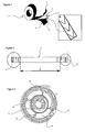
- the roll (1) is composed of a band (2) wound.
- This strip (2) is covered on both sides with peelable protective coatings (3, 4).
- the coating (3) covers adhesive with high adhesive power, allowing the bonding of the strip (2) on a flat cable.
- Said strip (2) is also covered, on the opposite side, with a soft material (6), either a low adhesion adhesive, or a synthetic material also having a limited adhesion ability, for example by suction .
- a soft material (6) either a low adhesion adhesive, or a synthetic material also having a limited adhesion ability, for example by suction .
- the flat cables (7) have at their two ends connection means (8, 9) to connectors located in the annular housing, respectively on the rotor and on the stator.
- the flat cable (7) is coated, over a distance I covering almost all of its total length, to the vicinity of the connection ends, the strip (2) appearing in figure 1 .
- the figure 3 shows a rotating contact provided with four flat cables (7), offset by about ⁇ 2 rds, each having a portion partially wound against the inner wall (11) of the annular housing (10), and a portion wrapped around its outer wall (12).
- the inner wall (11) may belong to the rotor, while the outer wall (12) belongs to the stator.
- each flat cable (7) comprises a loop (13, 14, 15, 16) reversing path.
- these cables (7) are simply coated with a strip (2) as shown in FIG. figure 1 , whose face (5) is glued against the flat cable (7), and the face (6) is coated with a material having properties that make it suitable for replacing fat.
- the coating (6) can either cover the entire surface of the strip (2), assuming that the chosen material has a sufficiently low adhesive power, or cover only a portion of the surface of the face concerned of the band (2), which leads to reducing the overall adhesion of the band (2).
Landscapes
- Engineering & Computer Science (AREA)
- Mechanical Engineering (AREA)
- Hooks, Suction Cups, And Attachment By Adhesive Means (AREA)
- Steering Controls (AREA)
- Adhesives Or Adhesive Processes (AREA)
- Connector Housings Or Holding Contact Members (AREA)
- Insulated Conductors (AREA)
Abstract
Description
- La présente invention concerne un contact tournant destiné à assurer la liaison électrique entre deux corps respectivement fixe et mobile animés d'un mouvement relatif de rotation autour d'un même axe.
- De tels dispositifs sont notamment employés dans l'industrie automobile, dans les colonnes de direction des véhicules, pour permettre la connexion électrique entre des éléments situés dans le volant, et par conséquent mobiles en rotation, et un circuit fixe câblé dans l'habitacle du véhicule.
- Ces contacts tournants comportent à titre essentiel un rotor et un stator, lesquels définissent entre eux un espace d'allure annulaire présentant deux parois en regard, qui peuvent être issues respectivement du rotor et du stator.
- Un ou plusieurs câbles plats sont disposés entre ces parois, et reliés à leurs extrémités à des connecteurs fixés aux parois.
- Dans l'hypothèse de l'invention, chaque câble comprend un premier tronçon s'enroulant au contact d'une des parois, puis une boucle d'inversion et un second tronçon s'enroulant au contact de l'autre paroi. Il s'agit par conséquent de contacts tournants utilisant des câbles courts.
- Plus précisément encore, les contacts tournants concernés par l'invention n'utilisent pas de mécanisme additionnels, par exemple à roues dentées censés améliorer et favoriser le contrôle du mouvement du câble notamment au niveau de la boucle.
- Le contrôle de ce mouvement est cependant au coeur du problème résolu par l'invention.
- Dans les hypothèses sans mécanisme additionnel, on dispose une certaine quantité de graisse sur une face de chaque câble plat, pour garantir à la fois une adhérence légère en sorties de la boucle, et le glissement continu de l'ensemble lorsque le contact tournant est mis en oeuvre. La graisse garantit la continuité fluide du double mouvement qui s'applique au câble plat, c'est-à-dire d'une part le défilement du câble au contact des deux parois, et d'autre part la progression de la boucle à l'intérieur du logement annulaire.
- L'application de graisse sur la surface extérieure des câbles permet d'une part d'assurer le glissement, et occasionne d'autre part une sorte de micro-adhésion empêchant des glissements intempestifs susceptibles de provoquer un décalage et/ou une détente du câble nuisible au contrôle de sa trajectoire et provoquant des bruits dans le système.
- Dans ces configurations, l'application de la graisse n'est cependant pas aisée, et en tout état de cause pas pratique à mettre en oeuvre dans le cadre d'un procédé de production. La fabrication est d'ailleurs onéreuse du fait des difficultés rencontrées pour l'application de la graisse sur le câble, et l'intégration des câbles graissés dans le boîtier du conducteur.
- Le but de l'invention est de remédier à ces inconvénients, et de proposer une solution permettant de faciliter l'assemblage des différents composants du contact tournant, conduisant de surcroît à des incidences économiques favorables.
- A cet effet, la face de chaque câble plat destinée à s'enrouler au contact des parois est recouverte d'une bande dont le côté extérieur est revêtu au moins partiellement d'une matière tendre ayant un pouvoir adhésif inférieur à 3N/100mm.
- En fait, la matière tendre en question remplace la graisse, c'est-à-dire qu'elle est supposée avoir un comportement similaire, pour permettre d'une part le glissement correct de la bande, et d'autre part la légère adhérence contre les parois intérieure et extérieure assurant la maîtrise fluide du mouvement.
- Selon une possibilité, cette matière peut être un composé basé sur du silicone. Une telle matière, assure une forme d'adhérence par aspiration plutôt que par collage, un peu à la manière d'une ventouse.
- Alternativement, cette matière peut être une colle acrylique. Dans ce cas, comme on l'a indiqué, le pouvoir adhésif de cette colle doit être léger, de manière à réaliser également un effet du type ventouse, avec un décollage des parois facile sous l'effet du glissement du câble.
- De préférence, ledit pouvoir adhésif peut être compris entre 2N/100mm et 3N/100mm.
- Pour maintenir ce pouvoir adhésif suffisamment faible, en utilisant les matières adhésives existantes, une solution additionnelle utilisée dans le cadre de l'invention est de maintenir la largeur de la bande inférieure à celle du câble plat. Dans ce cas-là, outre le choix d'une matière à pouvoir adhésif léger, seule une partie de la surface est concernée par la mise en oeuvre de cette matière, ce qui aboutit à réduire encore le pouvoir adhésif du revêtement. La diminution de la surface de contact donne d'ailleurs de bons résultats pour ce qui concerne l'objectif général de réduire le pouvoir adhésif du câble sur un côté.
- Alternativement, la bande peut être disposée en chevrons successifs. Dans cette seconde hypothèse, la surface de matière adhésives est aussi inférieure à la surface du câble plat, et son effet, ramené à la surface dudit câble, est par conséquent également atténué.
- Dans les deux cas, selon une possibilité, la surface de la bande peut être prévue sensiblement égale à la moitié de la surface de la face du câble qu'elle recouvre.
- Par ailleurs, le côté intérieur de la bande est revêtu d'une matière adhésive en vue de son collage contre le câble plat. Cette matière adhésive peut par exemple être aussi une colle acrylique, dont le pouvoir adhésif est cependant beaucoup moins critique que sur l'autre face.
- En tout état de cause, quelle que soit la matière adhésive utilisée, son pouvoir adhésif est choisi supérieur à 20 N/100mm. Cette valeur résulte de tests, qui établissent clairement qu'elle est suffisante.
- L'invention concerne également une bande destinée à être fixée sur une des faces d'un câble plat de contact tournant tel que décrit auparavant. Selon une caractéristique essentielle, cette bande est disposée en rouleau, les deux côtés de ladite bande étant alors revêtus d'une couche de protection pelable.
- Cette solution présente des avantages non négligeables en termes de procédés de fabrication, puisqu'il suffit de coller une telle bande sur un câble plat avant de le disposer à l'intérieur du logement annulaire.
- L'invention va à présent être décrite plus en détail, en référence aux figures, pour lesquelles :
- la
figure 1 représente, en perspective, un rouleau d'une bande selon l'invention ; - la
figure 2 est une vue en élévation d'un câble plat utilisable dans un contact tournant selon l'invention ; et - la
figure 3 est une vue en perspective d'un tel contact tournant muni de quatre câbles courts à boucles d'inversion de la trajectoire. - En référence à la
figure 1 , le rouleau (1) est composé d'une bande (2) enroulée. Cette bande (2) est recouverte, sur ses deux faces, de revêtements protecteurs (3, 4) pelables. D'un côté, c'est-à-dire sur une face (5) de la bande (2), le revêtement (3) recouvre de la colle à fort pouvoir adhésif, permettant le collage de la bande (2) sur un câble plat. - Ladite bande (2) est par ailleurs recouverte, sur le côté opposé, d'un matériau tendre (6), soit une colle à faible pouvoir adhésif, soit un matériau synthétique possédant également une aptitude limitée à l'adhésion, par exemple par aspiration.
- Lors du montage du contact tournant, comme par exemple celui qui apparaît en
figure 3 , les câbles plats (7), dont une configuration possible est illustrée enfigure 2 , sont munis, sur leur face destinée à entrer en contact avec les parois du logement annulaire, d'une bande (2) telle que décrite enfigure 1 . - Les câbles plats (7) comportent, à leurs deux extrémités, des moyens de connexion (8, 9) à des connecteurs situés dans le logement annulaire, respectivement sur le rotor et sur le stator. Le câble plat (7) est revêtu, sur une distance I couvrant la quasi totalité de sa longueur totale, jusqu'au voisinage des extrémités de connexion, de la bande (2) apparaissant en
figure 1 . - La
figure 3 montre un contact tournant muni de quatre câbles plats (7), décalés d'environ
figure 1 , dont la face (5) est collée contre la câble plat (7), et la face (6) est revêtue d'un matériau présentant des propriétés le rendant apte à remplacer la graisse. - L'exemple illustré par les figures n'est bien entendu pas exhaustif de l'invention, qui englobe notamment des variantes de matière et de forme. Ainsi, le revêtement (6) peut soit couvrir la totalité de la surface de la bande (2), dans l'hypothèse où le matériau choisi a un pouvoir adhésif suffisamment faible, soit ne couvrir qu'une portion de la surface de la face concernée de la bande (2), ce qui conduit à diminuer l'adhérence globale de la bande (2).
- C'est ce qui est montré en référence à la
figure 1 , dans l'encadré constituant un agrandissement de la face de la bande (2) à faible pouvoir adhésif, le matériau (6) choisi étant distribué sur ladite face sous forme de chevrons et n'occupant ainsi qu'une fraction limitée de la surface.
Claims (11)
- Contact tournant comportant un rotor et un stator définissant entre eux un espace d'allure annulaire présentant deux parois (11, 12) en regard entre lesquelles est disposé au moins un câble plat (7) dont les extrémités sont reliées à des connecteurs fixés auxdites parois (11, 12), chaque câble (7) comprenant un premier tronçon s'enroulant au contact d'une des parois (11), une boucle d'inversion (13, 14, 15, 16) et un second tronçon s'enroulant au contact de l'autre paroi (12), caractérisé en ce que la face du câble plat (7) destinée à s'enrouler au contact des parois (11, 12) est recouverte d'une bande (2) dont le côté extérieur est revêtu au moins partiellement d'une matière tendre (6) ayant un pouvoir adhésif inférieur à 3N/100mm.
- Contact tournant selon la revendication précédente, caractérisé en ce que ladite matière (6) est un composé basé sur du silicone.
- Contact tournant selon la revendication 1, caractérisé en ce que ladite matière (6) est une colle acrylique.
- Contact tournant selon la revendication précédente, caractérisé en ce que la colle acrylique a un pouvoir adhésif compris entre 2N/100mm et 3N/100mm.
- Contact tournant selon l'une quelconque des revendications précédentes, caractérisé en ce que la bande (2) ou la matière adhésive (6) a une largeur inférieure à celle du câble plat (7).
- Contact tournant selon l'une quelconque des revendications 1 à 4, caractérisé en ce que la bande (2) ou la matière adhésive (6) est conformée en chevrons successifs.
- Contact tournant selon l'une des revendications 5 et 6, caractérisé en ce que la surface de la bande (2) est sensiblement égale à la moitié de la surface de la face du câble (7) qu'elle recouvre.
- Contact tournant selon l'une quelconque des revendications précédentes, caractérisé en ce que le côté intérieur (5) de la bande (2) est revêtu d'une matière adhésive en vue de son collage contre le câble plat (7).
- Contact tournant selon la revendication précédente, caractérisé en ce que ladite matière adhésive est une colle acrylique.
- Contact tournant selon l'une quelconque des revendications 8 et 9, caractérisé en ce que le pouvoir adhésif de ladite matière adhésive est supérieur à 20 N/100mm.
- Bande (2) destinée à être fixée sur l'une des faces d'un câble plat (7) de contact tournant selon les revendications précédentes, caractérisée en ce qu'elle est disposée en rouleau, les deux côtés de ladite bande (2) étant revêtus d'une couche de protection (3, 4) pelable.
Priority Applications (3)
| Application Number | Priority Date | Filing Date | Title |
|---|---|---|---|
| AT08360012T ATE477967T1 (de) | 2008-05-16 | 2008-05-16 | Drehkontakt, dessen kabel mit einem klebeband versehen ist |
| DE602008002231T DE602008002231D1 (de) | 2008-05-16 | 2008-05-16 | Drehkontakt, dessen Kabel mit einem Klebeband versehen ist |
| EP08360012A EP2123518B1 (fr) | 2008-05-16 | 2008-05-16 | Contact tournant dont le câble est revêtu d'une bande adhésive |
Applications Claiming Priority (1)
| Application Number | Priority Date | Filing Date | Title |
|---|---|---|---|
| EP08360012A EP2123518B1 (fr) | 2008-05-16 | 2008-05-16 | Contact tournant dont le câble est revêtu d'une bande adhésive |
Publications (2)
| Publication Number | Publication Date |
|---|---|
| EP2123518A1 true EP2123518A1 (fr) | 2009-11-25 |
| EP2123518B1 EP2123518B1 (fr) | 2010-08-18 |
Family
ID=39925018
Family Applications (1)
| Application Number | Title | Priority Date | Filing Date |
|---|---|---|---|
| EP08360012A Not-in-force EP2123518B1 (fr) | 2008-05-16 | 2008-05-16 | Contact tournant dont le câble est revêtu d'une bande adhésive |
Country Status (3)
| Country | Link |
|---|---|
| EP (1) | EP2123518B1 (fr) |
| AT (1) | ATE477967T1 (fr) |
| DE (1) | DE602008002231D1 (fr) |
Citations (2)
| Publication number | Priority date | Publication date | Assignee | Title |
|---|---|---|---|---|
| WO1999029004A1 (fr) * | 1997-11-28 | 1999-06-10 | Furukawa Electric Co., Ltd. | Connecteur rotatif |
| GB2400504A (en) * | 2000-09-07 | 2004-10-13 | Methode Electronics Inc | Rotary connector having flat cable with separation member attached to cable surface |
-
2008
- 2008-05-16 DE DE602008002231T patent/DE602008002231D1/de active Active
- 2008-05-16 AT AT08360012T patent/ATE477967T1/de not_active IP Right Cessation
- 2008-05-16 EP EP08360012A patent/EP2123518B1/fr not_active Not-in-force
Patent Citations (2)
| Publication number | Priority date | Publication date | Assignee | Title |
|---|---|---|---|---|
| WO1999029004A1 (fr) * | 1997-11-28 | 1999-06-10 | Furukawa Electric Co., Ltd. | Connecteur rotatif |
| GB2400504A (en) * | 2000-09-07 | 2004-10-13 | Methode Electronics Inc | Rotary connector having flat cable with separation member attached to cable surface |
Also Published As
| Publication number | Publication date |
|---|---|
| ATE477967T1 (de) | 2010-09-15 |
| EP2123518B1 (fr) | 2010-08-18 |
| DE602008002231D1 (de) | 2010-09-30 |
Similar Documents
| Publication | Publication Date | Title |
|---|---|---|
| CA2683552C (fr) | Barrette de roue et roue specialement adaptee | |
| FR2984803A1 (fr) | Pneumatique cloute perfectionne | |
| FR2833679A1 (fr) | Gaine de protection refermable par recouvrement et utilisation de cette gaine | |
| FR2753574A1 (fr) | Contacteur tournant a ruban, en particulier pour vehicules automobiles | |
| FR3057717A1 (fr) | Systeme sous-marin de raccordement electrique | |
| FR2942746A1 (fr) | Pneumatique pour bicyclette. | |
| EP0262022A1 (fr) | Tuyauterie pour installation de nettoyage centralisée par aspiration et procédé de réalisation d'un tube utilisable dans une telle tuyauterie | |
| EP2123518B1 (fr) | Contact tournant dont le câble est revêtu d'une bande adhésive | |
| FR3074242A1 (fr) | Porte-satellites pour actionneur de frein a reduction differentielle et procede de fabrication dudit porte-satellites | |
| EP4584515A1 (fr) | Dispositif de changement de vitesse pour engin de mobilité | |
| WO2014057214A1 (fr) | Procédé de mise à la masse d'un composant électrique | |
| FR2699013A1 (fr) | Gaine pour faisceaux de câbles ou fils électriques. | |
| FR2873327A1 (fr) | Dispositif permettant de reproduire les conditions d'une conduite sur surface glissante pour un vehicule a roues et son procede de montage | |
| EP3464950A1 (fr) | Démarreur muni d'un pignon ayant au moins une dent profilée | |
| EP3074294B1 (fr) | Platine de commutateur electrique et colonne de direction d'un vehicule | |
| FR2554985A1 (fr) | Conduit annele juxtaposable par emboitement | |
| EP1669629B1 (fr) | Maintien de cable de frein | |
| EP3066359A1 (fr) | Differentiel de transmission comportant des rondelles de friction munies de moyens indicateurs de presence | |
| FR3083030A1 (fr) | Demarreur ayant un porte balai pour une longueur de balai optimisee | |
| EP3465834A1 (fr) | Connecteur pour véhicule automobile comportant un contact femelle qui comporte une douille avec au moins une languette flexible | |
| EP0923165B1 (fr) | Dispositif imperdable pour douille d'ancrage de conduit | |
| FR3139050A1 (fr) | Ensemble de rangement pour un câble de recharge électrique d’un véhicule automobile électrifié | |
| EP0669481A1 (fr) | Système de détection d'usure de garniture de friction de frein à disque ou à tambour | |
| FR2875342A1 (fr) | Ensemble de raccordement electrique | |
| FR2461776A1 (fr) | Cable profile |
Legal Events
| Date | Code | Title | Description |
|---|---|---|---|
| PUAI | Public reference made under article 153(3) epc to a published international application that has entered the european phase |
Free format text: ORIGINAL CODE: 0009012 |
|
| 17P | Request for examination filed |
Effective date: 20080611 |
|
| AK | Designated contracting states |
Kind code of ref document: A1 Designated state(s): AT BE BG CH CY CZ DE DK EE ES FI FR GB GR HR HU IE IS IT LI LT LU LV MC MT NL NO PL PT RO SE SI SK TR |
|
| AX | Request for extension of the european patent |
Extension state: AL BA MK RS |
|
| GRAP | Despatch of communication of intention to grant a patent |
Free format text: ORIGINAL CODE: EPIDOSNIGR1 |
|
| GRAS | Grant fee paid |
Free format text: ORIGINAL CODE: EPIDOSNIGR3 |
|
| GRAA | (expected) grant |
Free format text: ORIGINAL CODE: 0009210 |
|
| AKX | Designation fees paid |
Designated state(s): AT BE BG CH CY CZ DE DK EE ES FI FR GB GR HR HU IE IS IT LI LT LU LV MC MT NL NO PL PT RO SE SI SK TR |
|
| AK | Designated contracting states |
Kind code of ref document: B1 Designated state(s): AT BE BG CH CY CZ DE DK EE ES FI FR GB GR HR HU IE IS IT LI LT LU LV MC MT NL NO PL PT RO SE SI SK TR |
|
| REG | Reference to a national code |
Ref country code: GB Ref legal event code: FG4D Free format text: NOT ENGLISH |
|
| REG | Reference to a national code |
Ref country code: CH Ref legal event code: EP |
|
| REG | Reference to a national code |
Ref country code: IE Ref legal event code: FG4D Free format text: LANGUAGE OF EP DOCUMENT: FRENCH |
|
| REF | Corresponds to: |
Ref document number: 602008002231 Country of ref document: DE Date of ref document: 20100930 Kind code of ref document: P |
|
| REG | Reference to a national code |
Ref country code: NL Ref legal event code: VDEP Effective date: 20100818 |
|
| LTIE | Lt: invalidation of european patent or patent extension |
Effective date: 20100818 |
|
| PG25 | Lapsed in a contracting state [announced via postgrant information from national office to epo] |
Ref country code: NO Free format text: LAPSE BECAUSE OF FAILURE TO SUBMIT A TRANSLATION OF THE DESCRIPTION OR TO PAY THE FEE WITHIN THE PRESCRIBED TIME-LIMIT Effective date: 20101118 Ref country code: AT Free format text: LAPSE BECAUSE OF FAILURE TO SUBMIT A TRANSLATION OF THE DESCRIPTION OR TO PAY THE FEE WITHIN THE PRESCRIBED TIME-LIMIT Effective date: 20100818 Ref country code: LT Free format text: LAPSE BECAUSE OF FAILURE TO SUBMIT A TRANSLATION OF THE DESCRIPTION OR TO PAY THE FEE WITHIN THE PRESCRIBED TIME-LIMIT Effective date: 20100818 Ref country code: FI Free format text: LAPSE BECAUSE OF FAILURE TO SUBMIT A TRANSLATION OF THE DESCRIPTION OR TO PAY THE FEE WITHIN THE PRESCRIBED TIME-LIMIT Effective date: 20100818 |
|
| PG25 | Lapsed in a contracting state [announced via postgrant information from national office to epo] |
Ref country code: BG Free format text: LAPSE BECAUSE OF FAILURE TO SUBMIT A TRANSLATION OF THE DESCRIPTION OR TO PAY THE FEE WITHIN THE PRESCRIBED TIME-LIMIT Effective date: 20101118 Ref country code: CY Free format text: LAPSE BECAUSE OF FAILURE TO SUBMIT A TRANSLATION OF THE DESCRIPTION OR TO PAY THE FEE WITHIN THE PRESCRIBED TIME-LIMIT Effective date: 20100818 Ref country code: HR Free format text: LAPSE BECAUSE OF FAILURE TO SUBMIT A TRANSLATION OF THE DESCRIPTION OR TO PAY THE FEE WITHIN THE PRESCRIBED TIME-LIMIT Effective date: 20100818 Ref country code: IS Free format text: LAPSE BECAUSE OF FAILURE TO SUBMIT A TRANSLATION OF THE DESCRIPTION OR TO PAY THE FEE WITHIN THE PRESCRIBED TIME-LIMIT Effective date: 20101218 Ref country code: PL Free format text: LAPSE BECAUSE OF FAILURE TO SUBMIT A TRANSLATION OF THE DESCRIPTION OR TO PAY THE FEE WITHIN THE PRESCRIBED TIME-LIMIT Effective date: 20100818 Ref country code: SI Free format text: LAPSE BECAUSE OF FAILURE TO SUBMIT A TRANSLATION OF THE DESCRIPTION OR TO PAY THE FEE WITHIN THE PRESCRIBED TIME-LIMIT Effective date: 20100818 |
|
| REG | Reference to a national code |
Ref country code: IE Ref legal event code: FD4D |
|
| PG25 | Lapsed in a contracting state [announced via postgrant information from national office to epo] |
Ref country code: SE Free format text: LAPSE BECAUSE OF FAILURE TO SUBMIT A TRANSLATION OF THE DESCRIPTION OR TO PAY THE FEE WITHIN THE PRESCRIBED TIME-LIMIT Effective date: 20100818 Ref country code: LV Free format text: LAPSE BECAUSE OF FAILURE TO SUBMIT A TRANSLATION OF THE DESCRIPTION OR TO PAY THE FEE WITHIN THE PRESCRIBED TIME-LIMIT Effective date: 20100818 Ref country code: GR Free format text: LAPSE BECAUSE OF FAILURE TO SUBMIT A TRANSLATION OF THE DESCRIPTION OR TO PAY THE FEE WITHIN THE PRESCRIBED TIME-LIMIT Effective date: 20101119 Ref country code: NL Free format text: LAPSE BECAUSE OF FAILURE TO SUBMIT A TRANSLATION OF THE DESCRIPTION OR TO PAY THE FEE WITHIN THE PRESCRIBED TIME-LIMIT Effective date: 20100818 |
|
| PG25 | Lapsed in a contracting state [announced via postgrant information from national office to epo] |
Ref country code: DK Free format text: LAPSE BECAUSE OF FAILURE TO SUBMIT A TRANSLATION OF THE DESCRIPTION OR TO PAY THE FEE WITHIN THE PRESCRIBED TIME-LIMIT Effective date: 20100818 Ref country code: IE Free format text: LAPSE BECAUSE OF FAILURE TO SUBMIT A TRANSLATION OF THE DESCRIPTION OR TO PAY THE FEE WITHIN THE PRESCRIBED TIME-LIMIT Effective date: 20100818 |
|
| PG25 | Lapsed in a contracting state [announced via postgrant information from national office to epo] |
Ref country code: RO Free format text: LAPSE BECAUSE OF FAILURE TO SUBMIT A TRANSLATION OF THE DESCRIPTION OR TO PAY THE FEE WITHIN THE PRESCRIBED TIME-LIMIT Effective date: 20100818 Ref country code: CZ Free format text: LAPSE BECAUSE OF FAILURE TO SUBMIT A TRANSLATION OF THE DESCRIPTION OR TO PAY THE FEE WITHIN THE PRESCRIBED TIME-LIMIT Effective date: 20100818 Ref country code: IT Free format text: LAPSE BECAUSE OF FAILURE TO SUBMIT A TRANSLATION OF THE DESCRIPTION OR TO PAY THE FEE WITHIN THE PRESCRIBED TIME-LIMIT Effective date: 20100818 Ref country code: SK Free format text: LAPSE BECAUSE OF FAILURE TO SUBMIT A TRANSLATION OF THE DESCRIPTION OR TO PAY THE FEE WITHIN THE PRESCRIBED TIME-LIMIT Effective date: 20100818 Ref country code: EE Free format text: LAPSE BECAUSE OF FAILURE TO SUBMIT A TRANSLATION OF THE DESCRIPTION OR TO PAY THE FEE WITHIN THE PRESCRIBED TIME-LIMIT Effective date: 20100818 |
|
| PLBE | No opposition filed within time limit |
Free format text: ORIGINAL CODE: 0009261 |
|
| STAA | Information on the status of an ep patent application or granted ep patent |
Free format text: STATUS: NO OPPOSITION FILED WITHIN TIME LIMIT |
|
| PG25 | Lapsed in a contracting state [announced via postgrant information from national office to epo] |
Ref country code: ES Free format text: LAPSE BECAUSE OF FAILURE TO SUBMIT A TRANSLATION OF THE DESCRIPTION OR TO PAY THE FEE WITHIN THE PRESCRIBED TIME-LIMIT Effective date: 20101129 |
|
| 26N | No opposition filed |
Effective date: 20110519 |
|
| REG | Reference to a national code |
Ref country code: DE Ref legal event code: R097 Ref document number: 602008002231 Country of ref document: DE Effective date: 20110519 |
|
| BERE | Be: lapsed |
Owner name: DELPHI TECHNOLOGIES, INC. Effective date: 20110531 |
|
| PG25 | Lapsed in a contracting state [announced via postgrant information from national office to epo] |
Ref country code: MC Free format text: LAPSE BECAUSE OF NON-PAYMENT OF DUE FEES Effective date: 20110531 Ref country code: MT Free format text: LAPSE BECAUSE OF FAILURE TO SUBMIT A TRANSLATION OF THE DESCRIPTION OR TO PAY THE FEE WITHIN THE PRESCRIBED TIME-LIMIT Effective date: 20100818 |
|
| PG25 | Lapsed in a contracting state [announced via postgrant information from national office to epo] |
Ref country code: BE Free format text: LAPSE BECAUSE OF NON-PAYMENT OF DUE FEES Effective date: 20110531 |
|
| REG | Reference to a national code |
Ref country code: CH Ref legal event code: PL |
|
| GBPC | Gb: european patent ceased through non-payment of renewal fee |
Effective date: 20120516 |
|
| PG25 | Lapsed in a contracting state [announced via postgrant information from national office to epo] |
Ref country code: CH Free format text: LAPSE BECAUSE OF NON-PAYMENT OF DUE FEES Effective date: 20120531 Ref country code: LI Free format text: LAPSE BECAUSE OF NON-PAYMENT OF DUE FEES Effective date: 20120531 |
|
| PG25 | Lapsed in a contracting state [announced via postgrant information from national office to epo] |
Ref country code: GB Free format text: LAPSE BECAUSE OF NON-PAYMENT OF DUE FEES Effective date: 20120516 |
|
| PG25 | Lapsed in a contracting state [announced via postgrant information from national office to epo] |
Ref country code: LU Free format text: LAPSE BECAUSE OF NON-PAYMENT OF DUE FEES Effective date: 20110516 |
|
| PG25 | Lapsed in a contracting state [announced via postgrant information from national office to epo] |
Ref country code: PT Free format text: LAPSE BECAUSE OF NON-PAYMENT OF DUE FEES Effective date: 20100818 |
|
| PGFP | Annual fee paid to national office [announced via postgrant information from national office to epo] |
Ref country code: DE Payment date: 20130530 Year of fee payment: 6 |
|
| PGFP | Annual fee paid to national office [announced via postgrant information from national office to epo] |
Ref country code: FR Payment date: 20130606 Year of fee payment: 6 |
|
| PG25 | Lapsed in a contracting state [announced via postgrant information from national office to epo] |
Ref country code: TR Free format text: LAPSE BECAUSE OF FAILURE TO SUBMIT A TRANSLATION OF THE DESCRIPTION OR TO PAY THE FEE WITHIN THE PRESCRIBED TIME-LIMIT Effective date: 20100818 |
|
| PG25 | Lapsed in a contracting state [announced via postgrant information from national office to epo] |
Ref country code: HU Free format text: LAPSE BECAUSE OF FAILURE TO SUBMIT A TRANSLATION OF THE DESCRIPTION OR TO PAY THE FEE WITHIN THE PRESCRIBED TIME-LIMIT Effective date: 20100818 |
|
| REG | Reference to a national code |
Ref country code: DE Ref legal event code: R119 Ref document number: 602008002231 Country of ref document: DE |
|
| REG | Reference to a national code |
Ref country code: FR Ref legal event code: ST Effective date: 20150130 |
|
| REG | Reference to a national code |
Ref country code: DE Ref legal event code: R119 Ref document number: 602008002231 Country of ref document: DE Effective date: 20141202 |
|
| PG25 | Lapsed in a contracting state [announced via postgrant information from national office to epo] |
Ref country code: DE Free format text: LAPSE BECAUSE OF NON-PAYMENT OF DUE FEES Effective date: 20141202 |
|
| PG25 | Lapsed in a contracting state [announced via postgrant information from national office to epo] |
Ref country code: FR Free format text: LAPSE BECAUSE OF NON-PAYMENT OF DUE FEES Effective date: 20140602 |