EP2123484A1 - Pneumatic tire - Google Patents
Pneumatic tire Download PDFInfo
- Publication number
- EP2123484A1 EP2123484A1 EP08721808A EP08721808A EP2123484A1 EP 2123484 A1 EP2123484 A1 EP 2123484A1 EP 08721808 A EP08721808 A EP 08721808A EP 08721808 A EP08721808 A EP 08721808A EP 2123484 A1 EP2123484 A1 EP 2123484A1
- Authority
- EP
- European Patent Office
- Prior art keywords
- groove
- pneumatic tire
- tire
- wear rate
- circumferential main
- Prior art date
- Legal status (The legal status is an assumption and is not a legal conclusion. Google has not performed a legal analysis and makes no representation as to the accuracy of the status listed.)
- Granted
Links
Images


Classifications
-
- B—PERFORMING OPERATIONS; TRANSPORTING
- B60—VEHICLES IN GENERAL
- B60C—VEHICLE TYRES; TYRE INFLATION; TYRE CHANGING; CONNECTING VALVES TO INFLATABLE ELASTIC BODIES IN GENERAL; DEVICES OR ARRANGEMENTS RELATED TO TYRES
- B60C11/00—Tyre tread bands; Tread patterns; Anti-skid inserts
- B60C11/03—Tread patterns
- B60C11/0327—Tread patterns characterised by special properties of the tread pattern
- B60C11/033—Tread patterns characterised by special properties of the tread pattern by the void or net-to-gross ratios of the patterns
-
- B—PERFORMING OPERATIONS; TRANSPORTING
- B60—VEHICLES IN GENERAL
- B60C—VEHICLE TYRES; TYRE INFLATION; TYRE CHANGING; CONNECTING VALVES TO INFLATABLE ELASTIC BODIES IN GENERAL; DEVICES OR ARRANGEMENTS RELATED TO TYRES
- B60C11/00—Tyre tread bands; Tread patterns; Anti-skid inserts
- B60C11/01—Shape of the shoulders between tread and sidewall, e.g. rounded, stepped or cantilevered
-
- B—PERFORMING OPERATIONS; TRANSPORTING
- B60—VEHICLES IN GENERAL
- B60C—VEHICLE TYRES; TYRE INFLATION; TYRE CHANGING; CONNECTING VALVES TO INFLATABLE ELASTIC BODIES IN GENERAL; DEVICES OR ARRANGEMENTS RELATED TO TYRES
- B60C11/00—Tyre tread bands; Tread patterns; Anti-skid inserts
- B60C11/03—Tread patterns
- B60C11/0306—Patterns comprising block rows or discontinuous ribs
- B60C11/0309—Patterns comprising block rows or discontinuous ribs further characterised by the groove cross-section
-
- B—PERFORMING OPERATIONS; TRANSPORTING
- B60—VEHICLES IN GENERAL
- B60C—VEHICLE TYRES; TYRE INFLATION; TYRE CHANGING; CONNECTING VALVES TO INFLATABLE ELASTIC BODIES IN GENERAL; DEVICES OR ARRANGEMENTS RELATED TO TYRES
- B60C11/00—Tyre tread bands; Tread patterns; Anti-skid inserts
- B60C11/03—Tread patterns
- B60C11/12—Tread patterns characterised by the use of narrow slits or incisions, e.g. sipes
-
- B—PERFORMING OPERATIONS; TRANSPORTING
- B60—VEHICLES IN GENERAL
- B60C—VEHICLE TYRES; TYRE INFLATION; TYRE CHANGING; CONNECTING VALVES TO INFLATABLE ELASTIC BODIES IN GENERAL; DEVICES OR ARRANGEMENTS RELATED TO TYRES
- B60C11/00—Tyre tread bands; Tread patterns; Anti-skid inserts
- B60C11/03—Tread patterns
- B60C11/12—Tread patterns characterised by the use of narrow slits or incisions, e.g. sipes
- B60C11/1236—Tread patterns characterised by the use of narrow slits or incisions, e.g. sipes with special arrangements in the tread pattern
-
- B—PERFORMING OPERATIONS; TRANSPORTING
- B60—VEHICLES IN GENERAL
- B60C—VEHICLE TYRES; TYRE INFLATION; TYRE CHANGING; CONNECTING VALVES TO INFLATABLE ELASTIC BODIES IN GENERAL; DEVICES OR ARRANGEMENTS RELATED TO TYRES
- B60C11/00—Tyre tread bands; Tread patterns; Anti-skid inserts
- B60C11/03—Tread patterns
- B60C11/13—Tread patterns characterised by the groove cross-section, e.g. for buttressing or preventing stone-trapping
-
- B—PERFORMING OPERATIONS; TRANSPORTING
- B60—VEHICLES IN GENERAL
- B60C—VEHICLE TYRES; TYRE INFLATION; TYRE CHANGING; CONNECTING VALVES TO INFLATABLE ELASTIC BODIES IN GENERAL; DEVICES OR ARRANGEMENTS RELATED TO TYRES
- B60C11/00—Tyre tread bands; Tread patterns; Anti-skid inserts
- B60C11/03—Tread patterns
- B60C11/13—Tread patterns characterised by the groove cross-section, e.g. for buttressing or preventing stone-trapping
- B60C11/1307—Tread patterns characterised by the groove cross-section, e.g. for buttressing or preventing stone-trapping with special features of the groove walls
- B60C11/1315—Tread patterns characterised by the groove cross-section, e.g. for buttressing or preventing stone-trapping with special features of the groove walls having variable inclination angles, e.g. warped groove walls
-
- B—PERFORMING OPERATIONS; TRANSPORTING
- B60—VEHICLES IN GENERAL
- B60C—VEHICLE TYRES; TYRE INFLATION; TYRE CHANGING; CONNECTING VALVES TO INFLATABLE ELASTIC BODIES IN GENERAL; DEVICES OR ARRANGEMENTS RELATED TO TYRES
- B60C11/00—Tyre tread bands; Tread patterns; Anti-skid inserts
- B60C11/03—Tread patterns
- B60C11/13—Tread patterns characterised by the groove cross-section, e.g. for buttressing or preventing stone-trapping
- B60C11/1369—Tie bars for linking block elements and bridging the groove
-
- B—PERFORMING OPERATIONS; TRANSPORTING
- B60—VEHICLES IN GENERAL
- B60C—VEHICLE TYRES; TYRE INFLATION; TYRE CHANGING; CONNECTING VALVES TO INFLATABLE ELASTIC BODIES IN GENERAL; DEVICES OR ARRANGEMENTS RELATED TO TYRES
- B60C11/00—Tyre tread bands; Tread patterns; Anti-skid inserts
- B60C11/03—Tread patterns
- B60C2011/0337—Tread patterns characterised by particular design features of the pattern
- B60C2011/0339—Grooves
- B60C2011/0341—Circumferential grooves
- B60C2011/0348—Narrow grooves, i.e. having a width of less than 4 mm
-
- B—PERFORMING OPERATIONS; TRANSPORTING
- B60—VEHICLES IN GENERAL
- B60C—VEHICLE TYRES; TYRE INFLATION; TYRE CHANGING; CONNECTING VALVES TO INFLATABLE ELASTIC BODIES IN GENERAL; DEVICES OR ARRANGEMENTS RELATED TO TYRES
- B60C11/00—Tyre tread bands; Tread patterns; Anti-skid inserts
- B60C11/03—Tread patterns
- B60C2011/0337—Tread patterns characterised by particular design features of the pattern
- B60C2011/0386—Continuous ribs
- B60C2011/0397—Sacrificial ribs, i.e. ribs recessed from outer tread contour
-
- Y—GENERAL TAGGING OF NEW TECHNOLOGICAL DEVELOPMENTS; GENERAL TAGGING OF CROSS-SECTIONAL TECHNOLOGIES SPANNING OVER SEVERAL SECTIONS OF THE IPC; TECHNICAL SUBJECTS COVERED BY FORMER USPC CROSS-REFERENCE ART COLLECTIONS [XRACs] AND DIGESTS
- Y02—TECHNOLOGIES OR APPLICATIONS FOR MITIGATION OR ADAPTATION AGAINST CLIMATE CHANGE
- Y02T—CLIMATE CHANGE MITIGATION TECHNOLOGIES RELATED TO TRANSPORTATION
- Y02T10/00—Road transport of goods or passengers
- Y02T10/80—Technologies aiming to reduce greenhouse gasses emissions common to all road transportation technologies
- Y02T10/86—Optimisation of rolling resistance, e.g. weight reduction
-
- Y—GENERAL TAGGING OF NEW TECHNOLOGICAL DEVELOPMENTS; GENERAL TAGGING OF CROSS-SECTIONAL TECHNOLOGIES SPANNING OVER SEVERAL SECTIONS OF THE IPC; TECHNICAL SUBJECTS COVERED BY FORMER USPC CROSS-REFERENCE ART COLLECTIONS [XRACs] AND DIGESTS
- Y10—TECHNICAL SUBJECTS COVERED BY FORMER USPC
- Y10S—TECHNICAL SUBJECTS COVERED BY FORMER USPC CROSS-REFERENCE ART COLLECTIONS [XRACs] AND DIGESTS
- Y10S152/00—Resilient tires and wheels
- Y10S152/03—Slits in threads
Definitions
- the present invention relates to a pneumatic tire.
- the invention particularly relates to a pneumatic tire that achieves improved tire rolling resistance, while maintaining snow braking and wet performance.
- Pneumatic tires in recent years have widthwise grooves arranged in center and shoulder areas of a tread to ensure their braking and driving performance. Such a tread pattern is called a traction pattern. Pneumatic tires with a traction pattern have challenges to maintain snow braking and wet performance of the tire. Further, such pneumatic tires tend to have an increased tire rolling resistance due to a large number of widthwise grooves arranged thereon.
- Patent Document 1 discloses a known technology of a conventional pneumatic tire that is related to the present invention.
- the conventional pneumatic tire has wide grooves including a pair of main grooves that are provided on its tread outer surface to be away from an equatorial plane thereof toward tread edges by a distance 0.41 times to 0.75 times as large as half of a tread width W. Further, the tread outer surface is segmented to a center area positioned in a center portion between the paired main grooves in a width direction, and shoulder areas positioned between the center portion of the paired main grooves and the both tread edges.
- Patent Document 1 Japanese Patent Application Laid-open No. H11-34614
- An object of the present invention is to provide a pneumatic tire that achieves improved tire rolling resistance, while maintaining snow braking and wet performance.
- a groove area ratio for a wear rate 0% is Gs
- a groove area ratio for a wear rate 100% is Ge
- a difference Gs-Ge falls in a predetermined range.
- the reduction in the groove area ratio G is optimized from when the tire is new to when the tire is in the last stage of wearing. This ensures the reduction range of the groove area ratio G appropriately, providing an advantage of reducing the tire rolling resistance.
- the groove area ratio G for a wear rate 20% and the groove area ratio G for a wear rate 35% fall in predetermined ranges of (Gs-G)/(Gs-Ge).
- the reduction in the groove area ratio G is optimized in the early stage of wearing. This ensures the stiffness of the block arrays in the early stage of wearing, providing an advantage of reducing the tire rolling resistance from the early stage of wearing.
- the groove area ratio G of the tread for each wear rate is adjusted by providing a bottom-up section on bottom of the widthwise groove.
- the bottom-up sections of the widthwise grooves appear on the ground-engaging surface of the block arrays, so that the groove area B of the widthwise grooves is reduced.
- the groove area B of the widthwise grooves is optimized for each wear rate. This provides an advantage of adjusting the groove area ratio G of the tread appropriately for each wear rate.
- the groove area ratio G of the tread for each wear rate is adjusted by changing a groove wall angle of the widthwise groove along a groove depth direction.
- the groove width of the widthwise grooves is reduced due to the change in groove wall angle ⁇ , so that the groove area B of the widthwise grooves is reduced.
- the groove area B of the widthwise grooves 3 is optimized for each wear rate. This provides an advantage that the groove area ratio G of the tread is adjusted appropriately for each wear rate.
- the widthwise groove and the circumferential main groove respectively have groove depths h and h' that satisfy a relation of 0.30 ⁇ h1/h' ⁇ 0.70, and the widthwise groove and the circumferential main groove respectively have groove widths w and w' that satisfy a relation of 0.20 ⁇ w/w' ⁇ 0.50.
- a ratio h1/h' between the groove depth h of the widthwise groove and the groove depth h' of the circumferential main groove, and a ratio w/w' between the groove width w of the widthwise groove and the groove width w' of the circumferential main groove are optimized.
- the volume of the widthwise groove is maintained appropriately. This provides an advantage of maintaining snow braking performance of the tire.
- the total groove area A of the circumferential main grooves and the total groove area B of the widthwise grooves on the tire-ground contact surface satisfy a relation of 0.25 ⁇ B/(A+B) ⁇ 0.45, for the wear rate 0%.
- the ratio B/(A+B) between the total groove area B of the widthwise grooves and the total groove area A+B on the tire-ground contact surface is optimized. Accordingly, the block stiffness of the block arrays is optimized. This provides advantages of reducing the tire rolling resistance and improving the resistance to uneven wear of the tire.
- a plurality of closed sipes having openings toward the circumferential main groove are arranged in the block arrays segmented by the circumferential main grooves that are on outermost portions in the tire width direction.
- the arranged closed sipes reduce the ground contact pressure at the edges of the blocks, thus preventing uneven wear. Further, the closed sipes increase edge components of the block arrays, thus achieving improved tire traction. This provides an advantage of improving snow braking performance of the tire.
- At least one of the circumferential main grooves has a groove wall angle ⁇ that falls in a range of ⁇ 8 degrees.
- the range of the groove wall angle ⁇ of the circumferential main grooves is optimized. This provides an advantage of reducing the tire rolling resistance.
- the groove wall angle ⁇ of at least one of the circumferential main grooves changes along the tire circumferential direction.
- the stiffness of the land section (the block arrays) is improved due to the change in the groove wall angle ⁇ . This prevents the land section from bending down, providing an advantage of increasing the tire rolling resistance.
- the groove area ratio Gs for the wear rate 0% falls in a range of Gs ⁇ 0.25.
- the groove area ratio Gs for the wear rate 0% is optimized, so that the overall stiffness of the block arrays is ensured. This prevents the distortion of the block arrays when the tire contacts the ground, providing an advantage of reducing the tire rolling resistance.
- a small groove extending in the tire circumferential direction is formed on a width-direction outside edge of the tread.
- a small groove extending in the tire circumferential direction is formed in a buttress portion.
- the small grooves are closed when the tire contacts the ground. This reduces the ground contact pressure in the shoulder areas (the shoulder ribs) of the tread, thus preventing the uneven wear. This provides an advantage of improving the resistance to uneven wear of the tire.
- tread rubber having a thickness t falling in a range of 3.0 millimeters ⁇ t ⁇ 5.5 millimeters is provided from bottom of the circumferential main groove in a center area of the tread up to the belt reinforcing layer.
- the tread rubber of the bottom of the circumferential main grooves has an optimized thickness t. This provides an advantage of effectively reducing the tire rolling resistance.
- tread rubber when heated at 100°C, tread rubber has tan ⁇ falling in a range of 0:01 ⁇ tan ⁇ 0.10.
- the tread rubber has an optimized tan ⁇ , and therefore the hysteresis loss of the tread is reduced. This provides an advantage of effectively reducing the tire rolling resistance.
- the pneumatic tire according to the present invention is applied to a pneumatic radial tire for heavy load.
- the pneumatic radial tire for heavy load tends to have an increased tire rolling resistance.
- a groove area ratio for a wear rate 0% is Gs
- a groove area ratio for a wear rate 100% is Ge
- a difference Gs-Ge falls in a predetermined range.
- the reduction in the groove area ratio G is optimized from when the tire is new to when the tire is in the last stage of wearing. This ensures the reduction range of the groove area ratio G appropriately, providing an advantage of reducing the tire rolling resistance.
- the groove area ratio G for a wear rate 20% and the groove area ratio G for a wear rate 35% fall in predetermined ranges of (Gs-G)/(Gs-Ge).
- the reduction in the groove area ratio G is optimized in the early stage of wearing. This ensures the stiffness of the block arrays in the early stage of wearing, providing an advantage of reducing the tire rolling resistance from the early stage of wearing.
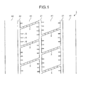
- Fig. 1 is a plan view of a tread of a pneumatic tire according to an embodiment of the present invention.
- Figs. 2 and 3 are a plan view ( Fig. 2 ) and a cross-sectional view ( Fig. 3 ) of a widthwise groove of the pneumatic tire shown in Fig. 1 .
- Figs. 4 and 5 are graphs for explaining performance of the pneumatic tire shown in Fig. 1 .
- Figs. 6 to 12 are explanatory views of modifications of the pneumatic tire shown in Fig. 1 .
- Fig. 13 is a table indicating performance test results of the pneumatic tire according to the embodiment of the present invention.
- a pneumatic tire 1 has a tread that includes: at least three circumferential main grooves 21 and 22 extending in a tire circumference direction; a plurality of widthwise grooves 3 extending in a tire width direction; and a plurality of block arrays 41 segmented by the circumferential main grooves 21 and 22 and the widthwise grooves 3 (see Fig. 1 ). With this arrangement, a traction pattern is formed based on the block arrays.
- the three circumferential main grooves 21 and 22 are formed in the tread (see Fig. 1 ).
- the widthwise grooves 3 are arranged to connect the adjoining circumferential main grooves 21 and 22.
- two block arrays 41, 41 are formed in the center area of the tread.
- ribs (shoulder ribs) 42 that are segmented by the circumferential main grooves 22 positioned on outer portions in the tire width direction and by tread edges.
- a wear rate of the tread is defined based on a condition where a remaining groove depth of the circumferential main grooves 21 and 22 is 1.6 millimeters as a reference (100%).
- a difference Gs-Ge falls in a range of Gs-Ge ⁇ 0.10, where Gs is a groove area ratio for a wear rate 0% and Ge is a groove area ratio for a wear rate 100% (see Fig. 4 ).
- Gs-Ge ⁇ 0.10 is satisfied between the groove area ratio Gs on the ground contact surface when the tire is new (the wear rate is 0%), and the groove area ratio Ge on the ground contact surface in the last stage of wearing (the wear rate is 100%).
- the groove area (A+B) is reduced by at least 10% or greater with respect to the tire-ground contact area X, on the tire-ground contact surface.
- the groove area ratio G for a wear rate 20% falls in a range of (Gs-G)/(Gs-Ge) ⁇ 0.30
- the groove area ratio G for a wear rate 35% falls in a range of (Gs-G)/(Gs-Ge) ⁇ 0.50 (see Fig. 5 ).
- a relation between the wear rate of the tread and the reduction in the groove area ratio G is defined so that the groove area A+B is reduced appropriately in the early stage of wearing.
- the relation between the wear rate and the reduction in the groove area ratio G is defined so that the reduction in the groove area ratio G in the early stage of wearing is larger than that of an existing conventional tire.
- the tire-ground contact surface refers to a surface where the tire makes contact with a flat plate when the tire attached to an applicable rim is applied with a specified internal pressure, while being placed perpendicularly to the flat plate with no-load and static conditions. Based on the tire-ground contact surface as a reference, the total groove area A of the circumferential main grooves 21 and 22, the total groove area B of the widthwise grooves 3, and the tire-ground contact area X are specified.
- the applicable rim refers to an "applicable rim” specified by the Japan Automobile Tyre Manufacturers Association, Inc. (JATMA), a “Design Rim” specified by the Tire and Rim Association, Inc. (TRA), and a “Measuring Rim” specified by the European Tyre and Rim Technical Organization (ETRTO).
- a normal internal pressure refers to a "maximum air pressure” specified by JATMA, a maximum value of "TIRE LOAD LIMITS AT VARIOUS COLD INFLATION PRESSURES" specified by TRA, and an "INFLATION PRESSURES" specified by ETRTO.
- a specified load refers to a "maximum load capacity" specified by JATMA, a maximum value of "TIRE LOAD LIMITS AT VARIOUS COLD INFLATION PRESSURES" specified by TRA, a "LOAD CAPACITY” specified by ETRTO.
- the specified internal pressure is an air pressure of 180 kPa, and the specified load is a maximum load capacity: 88%.
- a groove area ratio for a wear rate 0% is Gs
- a groove area ratio for a wear rate 100% is Ge
- a difference Gs-Ge falls in a predetermined range.
- the groove area ratio G for a wear rate 20% and the groove area ratio G for a wear rate 35% fall in predetermined ranges of (Gs-G)/(Gs-Ge).
- the reduction in the groove area ratio G is optimized in the early stage of wearing. This ensures the stiffness of the block arrays 41, 42 in the early stage of wearing, providing an advantage of reducing the tire rolling resistance from the early stage of wearing. For example, when the groove area ratio G in the early stage of wearing (when the wear rate ranges from 20% from 20% to 35%) falls out of the above range, the groove area ratio G is not reduced much. Thus, the tire rolling resistance is not effectively reduced.
- the pneumatic tire 1 includes, for example, bottom-up sections 31 and 32 on the bottom of the widthwise grooves 3.
- the groove area ratio G of the tread is adjusted for each wear rate (see Figs. 2 and 3 ).
- the widthwise grooves 3 include the bottom-up sections 31 and 32 on the bottom thereof, so that groove depths h1, h2, and h3 in respective portions of each widthwise groove 3 are changed by the bottom-up sections 31 and 32.
- the groove area ratio G of the tread is optimized for each wear rate.
- the bottom-up sections 31 and 32 of the widthwise grooves 3 appear on the ground-engaging surface of the block arrays 41, so that the groove area B of the widthwise grooves 3 is reduced.
- the groove area B of the widthwise grooves 3 is optimized for each wear rate. This provides an advantage of adjusting the groove area ratio G of the tread appropriately for each wear rate.
- the widthwise grooves 3 include the bottom-up sections 31 and 32 of a plurality of levels on the bottom thereof (see Figs. 2 and 3 ). Due to the bottom-up sections 31 and 32, the widthwise grooves 3 have the groove depths h1, h2, and h3 that are changed in a stepwise fashion. By adjusting the groove depths h1, h2, and h3, the groove area ratio G of the tread is optimized for each wear rate. Further, the bottom-up sections 31 and 32 are provided such that the widthwise grooves 3 have a small groove depth in center portions thereof, and increased groove depths toward openings (portions closer to the circumferential main grooves 21 and 22) in a stepwise fashion. This arrangement improves drainage performance of the widthwise grooves 3.
- the groove area ratio G of the tread may be adjusted for each wear rate by changing the groove wall angle ⁇ of the widthwise grooves 3 along a groove depth direction (see Figs. 6 and 7 ).
- the groove width of the widthwise grooves 3 is reduced due to the change in the groove wall angle ⁇ , so that the groove area B of the widthwise grooves 3 is reduced.
- the groove area B of the widthwise grooves 3 is optimized for each wear rate. This provides an advantage of adjusting the groove area ratio G of the tread appropriately for each wear rate.
- the widthwise grooves 3 have groove wall angles ⁇ 1 to ⁇ 3 of a plurality of levels along the groove depth direction (see Figs. 6 and 7 ).
- groove widths w1 to w3 are set for the respective groove depths h.
- the groove wall angles ⁇ 1 to ⁇ 3 are set so that the groove area ratio G of the tread falls in a desirable range for each wear rate when the block arrays 41 (42) are worn and their groove depth h is reduced.
- the pneumatic tire 1 is preferably arranged such that, when the wear rate is 0% (when the tire is new), the groove depth h of the widthwise grooves 3 and the groove depth h' of the circumferential main grooves 21 (22) satisfy a relation of 0.30 ⁇ hl/h' ⁇ 0.70, and also that the groove width w (w1) of the widthwise grooves 3 and the groove width w' of the circumferential main grooves 21 (22) satisfy a relation of 0.20 ⁇ w/w' ⁇ 0.50 (see Figs. 7 and 8 ).
- the ratio B/(A+B) between the total groove area B of the widthwise grooves 3 and the total groove area A+B on the tire-ground contact surface is optimized. Accordingly, the block stiffness of the block arrays 41 is optimized. This provides advantages of reducing the tire rolling resistance and improving the resistance to uneven wear of the tire. For example, when B/(A+B) ⁇ 0.25, the block stiffness is increased, causing uneven wear on the blocks more likely. When 0.45 ⁇ B/(A+B), the block stiffness is reduced, degrading the tire rolling resistance.
- a plurality of closed sipes 6 having openings toward the circumferential main grooves 22 are preferably arranged in the block arrays 41 that are segmented by the outermost circumferential main grooves 22 in the tire width direction (see Fig. 1 ).
- the closed sipes 6 are arranged in, among the block arrays 41, at least the block arrays 41 that are segmented by the outermost circumferential main grooves 22 in the tire width direction.
- the arranged closed sipes 6 increase edge components of the block arrays 41, thus achieving improved tire traction. This provides an advantage of improving snow braking performance of the tire.
- the two block arrays 41, 41 are formed in the center area of the tread by the three circumferential main grooves 21 and 22 and by the widthwise grooves 3 connecting the adjoining circumferential main grooves 21 and 22 (see Fig. 1 ).
- the closed sipes 6 having openings toward the circumferential main grooves 21(22) are formed.
- the closed sipes 6 are formed on both edges of the block arrays 41, and arranged along the circumferential main grooves 21(22). This arrangement improves the tire traction.
- the groove wall angle ⁇ of at least one of the circumferential main grooves 21(22) is preferably in the range of ⁇ 8 degrees (see Fig. 8 ).
- This arrangement optimizes the range of the groove wall angle ⁇ of the circumferential main groove(s) 21(22), providing an advantage of reducing the tire rolling resistance. For example, when ⁇ 8 degrees, with an increased distortion of the tread due to the rolling movement of the tire, the blocks bend down and the tire rolling resistance is increased. By setting ⁇ 8 degrees and making the blocks have trapezoid cross sections, the blocks are prevented from bending down, and the tire rolling resistance is increased.
- the groove wall angle ⁇ is defined as a tilt angle formed by a perpendicular line to the ground-engaging surface of the land section and by a groove wall surface of the circumferential main groove(s) 21(22), in a cross sectional view of the circumferential main groove(s) 21(22) taken along the groove depth direction.
- the groove wall angle ⁇ of at least one of the circumferential main grooves 21(22) is preferably changed along the tire circumferential direction (see Fig. 9 ).
- the groove wall angle ⁇ of the circumferential main groove(s) 21(22) is changed in a wave or zig-zag manner along the tire circumferential direction. This arrangement improves the stiffness of the land section (the block arrays 41) due to the change in the groove wall angle ⁇ . This prevents the land section from bending down, providing an advantage of increasing the tire rolling resistance.
- the groove area ratio Gs on the ground contact surface for the wear rate 0% (when the tire is new) preferably falls in a range of Gs ⁇ 0.25, and more preferably in a range of O.20 ⁇ Gs ⁇ 0.25.
- the groove area ratio Gs for the wear rate 0% is optimized, so that the overall stiffness of the block arrays 41 is ensured. This prevents the distortion of the block arrays 41 when the tire contacts the ground, providing an advantage of reducing the tire rolling resistance.
- small grooves extending in the tire circumferential direction are preferably formed on width-direction outside edges of the tread (see Fig. 10 ).
- small grooves 421 are formed in the shoulder ribs 42.
- the small grooves 421 extend in the tire circumferential direction, along width-direction outside edges of the shoulder ribs 42.
- narrow ribs 422 are formed on the width-direction outside edges of the shoulder ribs 42.
- small grooves 423 extending in the tire circumferential direction are preferably formed in a buttress portion (see Fig. 11 ). With this arrangement, the small grooves 423 are closed when the tire contacts the ground. Accordingly, the ground contact pressure in the shoulder areas (the shoulder ribs 42) of the tread is reduced, and the uneven wear is prevented. This provides an advantage of improving the resistance to uneven wear of the tire.
- tread rubber extending from the bottom of the circumferential main grooves 21 and 22 in the center area of the tread up to the belt reinforcing layer 5 preferably has a thickness t of 3.0 millimeters ⁇ t ⁇ 5.5 millimeters (see Fig. 12 ).
- This arrangement optimizes the thickness t of the tread rubber of the bottom of the circumferential main grooves 21 and 22, providing an advantage of efficiently reducing the tire rolling resistance. For example, when 5.5 millimeters ⁇ t, with an increased distortion of the tread rubber due to the tire contacting the ground, the blocks bend down and the tire rolling resistance is increased.
- t ⁇ 3.0 millimeters external injuries caused by stone drilling or the like easily reach the belt reinforcing layer. This may cause failure, or may easily cause cracking.
- the tread rubber when heated at 100°C, the tread rubber preferably has tan ⁇ falling in a range of 0.01 ⁇ tan ⁇ 0.10.
- This arrangement optimizes the tan ⁇ of the tread rubber, reducing the hysteresis loss of the tread.
- This provides an advantage of effectively reducing the tire rolling resistance. For example, when 0.10 ⁇ tan ⁇ , an increased amount of heat is generated in the tread rubber during rolling movement of the tire, and the tire rolling resistance is increased. When tan ⁇ 0.01, manufacturing performance of the tire is degraded.
- the pneumatic tire 1 is preferably applicable to a pneumatic radial tire for heavy load. Such a pneumatic tire tends to have an increased tire rolling resistance. Thus, it is advantageous to apply to such a pneumatic tire to achieve remarkable effects of reducing the rolling resistance.
- a plurality of pneumatic tires are tested under different conditions, regarding (1) low rolling resistance, (2) snow braking performance, (3) wet performance, and (4) resistance to uneven wear (see Fig. 13 ).
- pneumatic tires of size 275/80R22.5 are attached to applicable rims specified by JATMA, and a specified internal pressure is applied to the pneumatic tires.
- pneumatic tires are attached to a heavy load vehicle of a total vehicle weight of 25 tons (6 ⁇ 2), and a braking distance on a wet road surface is evaluated at a travel speed of 40 km/h or greater.
- the evaluation is indicated by index values using a conventional pneumatic tire (conventional example) as a reference (100). Larger index values are more preferable.
- the pneumatic tires 1 of invention examples 1 to 3 achieved improved low rolling resistances of the tires, while maintaining snow and wet performance of the tires. It is also found that the resistance to uneven wear of the tires is maintained. Comparing the invention examples 1 and 2, it is found that a ratio B/(A+B) between the total groove area A+B on the tire-ground contact surface and the total groove area B of the widthwise grooves 3 is optimized, so that the tire rolling resistance is reduced. Comparing the invention examples 2 and 3, it is found that the groove area ratio Gs for the wear rate 0% is optimized, so that the tire rolling resistance is reduced.
- a pneumatic tire according to the present invention is useful for improving tire rolling resistance, while maintaining snow braking and wet performance.
Landscapes
- Engineering & Computer Science (AREA)
- Mechanical Engineering (AREA)
- Tires In General (AREA)
Abstract
Description
- The present invention relates to a pneumatic tire. The invention particularly relates to a pneumatic tire that achieves improved tire rolling resistance, while maintaining snow braking and wet performance.
- Pneumatic tires in recent years have widthwise grooves arranged in center and shoulder areas of a tread to ensure their braking and driving performance. Such a tread pattern is called a traction pattern. Pneumatic tires with a traction pattern have challenges to maintain snow braking and wet performance of the tire. Further, such pneumatic tires tend to have an increased tire rolling resistance due to a large number of widthwise grooves arranged thereon.
-
Patent Document 1 discloses a known technology of a conventional pneumatic tire that is related to the present invention. The conventional pneumatic tire has wide grooves including a pair of main grooves that are provided on its tread outer surface to be away from an equatorial plane thereof toward tread edges by a distance 0.41 times to 0.75 times as large as half of a tread width W. Further, the tread outer surface is segmented to a center area positioned in a center portion between the paired main grooves in a width direction, and shoulder areas positioned between the center portion of the paired main grooves and the both tread edges. In the conventional tire in which a negative ratio is reduced to nearly equal values for the center area and each of the shoulder areas from when the tire is new to when it gets 75% wear, a reduction rate of negative ratio at the center area from when the tire is new to when it gets 75% wear is reduced. - Patent Document 1: Japanese Patent Application Laid-open No.
H11-34614 - An object of the present invention is to provide a pneumatic tire that achieves improved tire rolling resistance, while maintaining snow braking and wet performance.
- To achieve an object as described above, a pneumatic tire according to the present invention has a tread that includes at least three circumferential main grooves extending in a tire circumferential direction, a plurality of widthwise grooves extending in a tire width direction, and a plurality of block arrays segmented by the circumferential main grooves and the widthwise grooves, and provided that a ratio of a sum A+B of a total groove area A of the circumferential main grooves and a total groove area B of the widthwise grooves on a tire-ground contact surface to a tire-ground contact area X is defined as a groove area ratio G=(A+B)/X, and that a wear rate of the tread is defined based on a condition where a remaining groove depth of the circumferential main grooves is 1.6 millimeters as a reference (100%), a difference Gs-Ge falls in a range of Gs-Ge≥0.10, where Gs is a groove area ratio for a
wear rate 0% and Ge is a groove area ratio for awear rate 100%, the groove area ratio G for awear rate 20% is in a range of (Gs-G)/(Gs-Ge)≥0.30, and the groove area ratio G for awear rate 35% is in a range of (Gs-G)/(Gs-Ge)≥0.50. - In the pneumatic tire, (1) provided that a groove area ratio for a
wear rate 0% is Gs, and a groove area ratio for awear rate 100% is Ge, a difference Gs-Ge falls in a predetermined range. Thus, the reduction in the groove area ratio G is optimized from when the tire is new to when the tire is in the last stage of wearing. This ensures the reduction range of the groove area ratio G appropriately, providing an advantage of reducing the tire rolling resistance. Further, (2) the groove area ratio G for awear rate 20% and the groove area ratio G for awear rate 35% fall in predetermined ranges of (Gs-G)/(Gs-Ge). Thus, the reduction in the groove area ratio G is optimized in the early stage of wearing. This ensures the stiffness of the block arrays in the early stage of wearing, providing an advantage of reducing the tire rolling resistance from the early stage of wearing. - Further, in the pneumatic tire according to the present invention, the groove area ratio G of the tread for each wear rate is adjusted by providing a bottom-up section on bottom of the widthwise groove.
- In the pneumatic tire, when the block arrays are worn and their groove depth is reduced, the bottom-up sections of the widthwise grooves appear on the ground-engaging surface of the block arrays, so that the groove area B of the widthwise grooves is reduced. By adjusting the range for providing the bottom-up sections, the groove area B of the widthwise grooves is optimized for each wear rate. This provides an advantage of adjusting the groove area ratio G of the tread appropriately for each wear rate.
- Further, in the pneumatic tire according to the present invention, the groove area ratio G of the tread for each wear rate is adjusted by changing a groove wall angle of the widthwise groove along a groove depth direction.
- In the pneumatic tire, when the block arrays are worn and their groove depth is reduced, the groove width of the widthwise grooves is reduced due to the change in groove wall angle φ, so that the groove area B of the widthwise grooves is reduced. By adjusting the groove wall angle φ, the groove area B of the
widthwise grooves 3 is optimized for each wear rate. This provides an advantage that the groove area ratio G of the tread is adjusted appropriately for each wear rate. - Further, in the pneumatic tire according to the present invention, the widthwise groove and the circumferential main groove respectively have groove depths h and h' that satisfy a relation of 0.30≥h1/h'≤0.70, and the widthwise groove and the circumferential main groove respectively have groove widths w and w' that satisfy a relation of 0.20≤w/w'≤0.50.
- In the pneumatic tire, a ratio h1/h' between the groove depth h of the widthwise groove and the groove depth h' of the circumferential main groove, and a ratio w/w' between the groove width w of the widthwise groove and the groove width w' of the circumferential main groove are optimized. Thus, the volume of the widthwise groove is maintained appropriately. This provides an advantage of maintaining snow braking performance of the tire.
- Further, in the pneumatic tire according to the present invention, the total groove area A of the circumferential main grooves and the total groove area B of the widthwise grooves on the tire-ground contact surface satisfy a relation of 0.25≤B/(A+B)≤0.45, for the
wear rate 0%. - In the pneumatic tire, the ratio B/(A+B) between the total groove area B of the widthwise grooves and the total groove area A+B on the tire-ground contact surface is optimized. Accordingly, the block stiffness of the block arrays is optimized. This provides advantages of reducing the tire rolling resistance and improving the resistance to uneven wear of the tire.
- Further, in the pneumatic tire according to the present invention, a plurality of closed sipes having openings toward the circumferential main groove are arranged in the block arrays segmented by the circumferential main grooves that are on outermost portions in the tire width direction.
- In the pneumatic tire, the arranged closed sipes reduce the ground contact pressure at the edges of the blocks, thus preventing uneven wear. Further, the closed sipes increase edge components of the block arrays, thus achieving improved tire traction. This provides an advantage of improving snow braking performance of the tire.
- Further, in the pneumatic tire according to the present invention, at least one of the circumferential main grooves has a groove wall angle θ that falls in a range of θ≥8 degrees.
- In the pneumatic tire, the range of the groove wall angle θ of the circumferential main grooves is optimized. This provides an advantage of reducing the tire rolling resistance.
- Further, in the pneumatic tire according to the present invention, the groove wall angle θ of at least one of the circumferential main grooves changes along the tire circumferential direction.
- In the pneumatic tire, the stiffness of the land section (the block arrays) is improved due to the change in the groove wall angle θ. This prevents the land section from bending down, providing an advantage of increasing the tire rolling resistance.
- Further, in the pneumatic tire according to the present invention, the groove area ratio Gs for the
wear rate 0% falls in a range of Gs≤0.25. - In the pneumatic tire, the groove area ratio Gs for the
wear rate 0% is optimized, so that the overall stiffness of the block arrays is ensured. This prevents the distortion of the block arrays when the tire contacts the ground, providing an advantage of reducing the tire rolling resistance. - Further, in the pneumatic tire according to the present invention, a small groove extending in the tire circumferential direction is formed on a width-direction outside edge of the tread.
- In the pneumatic tire, when the tire contacts the ground, the narrow ribs formed by the small grooves are actively worn, so that uneven wear of the shoulder ribs is prevented. This provides an advantage of improving the resistance to uneven wear of the tire.
- Further, in the pneumatic tire according to the present invention, a small groove extending in the tire circumferential direction is formed in a buttress portion.
- In the pneumatic tire, the small grooves are closed when the tire contacts the ground. This reduces the ground contact pressure in the shoulder areas (the shoulder ribs) of the tread, thus preventing the uneven wear. This provides an advantage of improving the resistance to uneven wear of the tire.
- Further, in the pneumatic tire according to the present invention, when the tread includes a belt reinforcing layer, tread rubber having a thickness t falling in a range of 3.0 millimeters ≤t≤5.5 millimeters is provided from bottom of the circumferential main groove in a center area of the tread up to the belt reinforcing layer.
- In the pneumatic tire, the tread rubber of the bottom of the circumferential main grooves has an optimized thickness t. This provides an advantage of effectively reducing the tire rolling resistance.
- Further, in the pneumatic tire according to the present invention, when heated at 100°C, tread rubber has tanδ falling in a range of 0:01≤tanδ≤0.10.
- In the pneumatic tire, the tread rubber has an optimized tanδ, and therefore the hysteresis loss of the tread is reduced. This provides an advantage of effectively reducing the tire rolling resistance.
- Further, the pneumatic tire according to the present invention is applied to a pneumatic radial tire for heavy load.
- The pneumatic radial tire for heavy load tends to have an increased tire rolling resistance. Thus, it is advantageous to apply to such a pneumatic tire to achieve remarkable effects of reducing the rolling resistance.
- In a pneumatic tire according to the present invention, (1) provided that a groove area ratio for a
wear rate 0% is Gs, and a groove area ratio for awear rate 100% is Ge, a difference Gs-Ge falls in a predetermined range. Thus, the reduction in the groove area ratio G is optimized from when the tire is new to when the tire is in the last stage of wearing. This ensures the reduction range of the groove area ratio G appropriately, providing an advantage of reducing the tire rolling resistance. Further, (2) the groove area ratio G for awear rate 20% and the groove area ratio G for awear rate 35% fall in predetermined ranges of (Gs-G)/(Gs-Ge). Thus, the reduction in the groove area ratio G is optimized in the early stage of wearing. This ensures the stiffness of the block arrays in the early stage of wearing, providing an advantage of reducing the tire rolling resistance from the early stage of wearing. -
- [
Fig. 1] Fig. 1 is a plan view of a tread of a pneumatic tire according to an embodiment of the present invention. - [
Fig. 2] Fig. 2 is a plan view depicting a widthwise groove of the pneumatic tire shown inFig. 1 . - [
Fig. 3] Fig. 3 is a cross sectional view depicting a widthwise groove of the pneumatic tire shown inFig. 1 . - [
Fig. 4] Fig. 4 is a graph for explaining performance of the pneumatic tire shown inFig. 1 . - [
Fig. 5] Fig. 5 is a graph for explaining performance of the pneumatic tire shown inFig. 1 . - [
Fig. 6] Fig. 6 is an explanatory view of a modification of the pneumatic tire shown inFig. 1 . - [
Fig. 7] Fig. 7 is an explanatory view of a modification of the pneumatic tire shown inFig. 1 . - [
Fig. 8] Fig. 8 is an explanatory view of a modification of the pneumatic tire shown inFig. 1 . - [
Fig. 9] Fig. 9 is an explanatory view of a modification of the pneumatic tire shown inFig. 1 . - [
Fig. 10] Fig. 10 is an explanatory view of a modification of the pneumatic tire shown inFig. 1 . - [
Fig. 11] Fig. 11 is an explanatory view of a modification of the pneumatic tire shown inFig. 1 . - [
Fig. 12] Fig. 12 is an explanatory view of a modification of the pneumatic tire shown inFig. 1 . - [
Fig. 13] Fig. 13 is a table indicating performance test results of the pneumatic tire according to the embodiment of the present invention. -
- 1
- pneumatic tire
- 21, 22
- circumferential main groove
- 3
- widthwise groove
- 41
- block array
- 42
- shoulder rib
- 5
- belt reinforcing layer
- 6
- closed sipe
- 421
- small groove
- 422
- narrow rib
- 423
- small groove
- Exemplary embodiments of the present invention will be described in detail with reference to the accompanying drawings. The present invention is not limited by the embodiments. Constituting elements of the embodiments include elements that are convertible or feasible by a person skilled in the art, or elements being substantially the same as those elements. Further, a plurality of modifications described in this section may be combined in any way as long as being obvious to a person skilled in the art.
-
Fig. 1 is a plan view of a tread of a pneumatic tire according to an embodiment of the present invention.
Figs. 2 and 3 are a plan view (Fig. 2 ) and a cross-sectional view (Fig. 3 ) of a widthwise groove of the pneumatic tire shown inFig. 1 .Figs. 4 and 5 are graphs for explaining performance of the pneumatic tire shown inFig. 1 .Figs. 6 to 12 are explanatory views of modifications of the pneumatic tire shown inFig. 1 .Fig. 13 is a table indicating performance test results of the pneumatic tire according to the embodiment of the present invention. - A
pneumatic tire 1 has a tread that includes: at least three circumferentialmain grooves widthwise grooves 3 extending in a tire width direction; and a plurality ofblock arrays 41 segmented by the circumferentialmain grooves Fig. 1 ). With this arrangement, a traction pattern is formed based on the block arrays. - For example, in the present embodiment, the three circumferential
main grooves Fig. 1 ). In a center area of the tread, thewidthwise grooves 3 are arranged to connect the adjoining circumferentialmain grooves main grooves widthwise grooves 3, twoblock arrays main grooves 22 positioned on outer portions in the tire width direction and by tread edges. - A ratio of a sum A+B of a total groove area A of the circumferential
main grooves widthwise grooves 3 to a tire-ground contact area X on a tire-ground contact surface is referred to as a groove area ratio G=(A+B)/X. Further, a wear rate of the tread is defined based on a condition where a remaining groove depth of the circumferentialmain grooves - Here, (1) a difference Gs-Ge falls in a range of Gs-Ge≥0.10, where Gs is a groove area ratio for a
wear rate 0% and Ge is a groove area ratio for awear rate 100% (seeFig. 4 ). Specifically, the relation Gs-Ge≥0.10 is satisfied between the groove area ratio Gs on the ground contact surface when the tire is new (the wear rate is 0%), and the groove area ratio Ge on the ground contact surface in the last stage of wearing (the wear rate is 100%). In other words, when the tread is worn, the groove area (A+B) is reduced by at least 10% or greater with respect to the tire-ground contact area X, on the tire-ground contact surface. - Further, (2) The groove area ratio G for a
wear rate 20% falls in a range of (Gs-G)/(Gs-Ge)≥0.30, and the groove area ratio G for awear rate 35% falls in a range of (Gs-G)/(Gs-Ge)≥0.50 (seeFig. 5 ). In other words, a relation between the wear rate of the tread and the reduction in the groove area ratio G is defined so that the groove area A+B is reduced appropriately in the early stage of wearing. Specifically, the relation between the wear rate and the reduction in the groove area ratio G is defined so that the reduction in the groove area ratio G in the early stage of wearing is larger than that of an existing conventional tire. - The tire-ground contact surface refers to a surface where the tire makes contact with a flat plate when the tire attached to an applicable rim is applied with a specified internal pressure, while being placed perpendicularly to the flat plate with no-load and static conditions. Based on the tire-ground contact surface as a reference, the total groove area A of the circumferential
main grooves widthwise grooves 3, and the tire-ground contact area X are specified. - The applicable rim refers to an "applicable rim" specified by the Japan Automobile Tyre Manufacturers Association, Inc. (JATMA), a "Design Rim" specified by the Tire and Rim Association, Inc. (TRA), and a "Measuring Rim" specified by the European Tyre and Rim Technical Organization (ETRTO). A normal internal pressure refers to a "maximum air pressure" specified by JATMA, a maximum value of "TIRE LOAD LIMITS AT VARIOUS COLD INFLATION PRESSURES" specified by TRA, and an "INFLATION PRESSURES" specified by ETRTO. A specified load refers to a "maximum load capacity" specified by JATMA, a maximum value of "TIRE LOAD LIMITS AT VARIOUS COLD INFLATION PRESSURES" specified by TRA, a "LOAD CAPACITY" specified by ETRTO. As for passenger tires, the specified internal pressure is an air pressure of 180 kPa, and the specified load is a maximum load capacity: 88%.
- In a pneumatic tire according to the present invention, (1) provided that a groove area ratio for a
wear rate 0% is Gs, and a groove area ratio for awear rate 100% is Ge, a difference Gs-Ge falls in a predetermined range. Thus, the reduction in the groove area ratio G is optimized from when the tire is new to when the tire is in the last stage of wearing. This ensures the reduction range of the groove area ratio G appropriately, providing an advantage of reducing the tire rolling resistance. For example, when Gs-Ge<0.10, a variation in the groove area ratio G is small between the early stage and the last stage of wearing. Thus, effects of reducing the rolling resistance cannot be obtained sufficiently. - Further, (2) the groove area ratio G for a
wear rate 20% and the groove area ratio G for awear rate 35% fall in predetermined ranges of (Gs-G)/(Gs-Ge). Thus, the reduction in the groove area ratio G is optimized in the early stage of wearing. This ensures the stiffness of theblock arrays - To specify the groove area ratio G as described, the
pneumatic tire 1 includes, for example, bottom-upsections widthwise grooves 3. With this arrangement, the groove area ratio G of the tread is adjusted for each wear rate (seeFigs. 2 and 3 ). Specifically, thewidthwise grooves 3 include the bottom-upsections widthwise groove 3 are changed by the bottom-upsections - With this arrangement, when the
block arrays 41 are worn and their groove depth is reduced, the bottom-upsections widthwise grooves 3 appear on the ground-engaging surface of theblock arrays 41, so that the groove area B of thewidthwise grooves 3 is reduced. By adjusting the range for providing the bottom-upsections widthwise grooves 3 is optimized for each wear rate. This provides an advantage of adjusting the groove area ratio G of the tread appropriately for each wear rate. - For example, in the present embodiment, the
widthwise grooves 3 include the bottom-upsections Figs. 2 and 3 ). Due to the bottom-upsections widthwise grooves 3 have the groove depths h1, h2, and h3 that are changed in a stepwise fashion. By adjusting the groove depths h1, h2, and h3, the groove area ratio G of the tread is optimized for each wear rate. Further, the bottom-upsections widthwise grooves 3 have a small groove depth in center portions thereof, and increased groove depths toward openings (portions closer to the circumferentialmain grooves 21 and 22) in a stepwise fashion. This arrangement improves drainage performance of thewidthwise grooves 3. - In the
pneumatic tire 1, the groove area ratio G of the tread may be adjusted for each wear rate by changing the groove wall angle φ of thewidthwise grooves 3 along a groove depth direction (seeFigs. 6 and 7 ). - With this arrangement, when the block arrays 41 (42) are worn and their groove depth is reduced, the groove width of the
widthwise grooves 3 is reduced due to the change in the groove wall angle φ, so that the groove area B of thewidthwise grooves 3 is reduced. By adjusting the groove wall angle φ, the groove area B of thewidthwise grooves 3 is optimized for each wear rate. This provides an advantage of adjusting the groove area ratio G of the tread appropriately for each wear rate. - For example, in the present embodiment, the
widthwise grooves 3 have groove wall angles φ1 to φ3 of a plurality of levels along the groove depth direction (seeFigs. 6 and 7 ). With the groove wall angles φ1 to φ3, groove widths w1 to w3 are set for the respective groove depths h. The groove wall angles φ1 to φ3 (the groove widths w1 to w3) are set so that the groove area ratio G of the tread falls in a desirable range for each wear rate when the block arrays 41 (42) are worn and their groove depth h is reduced. - The
pneumatic tire 1 is preferably arranged such that, when the wear rate is 0% (when the tire is new), the groove depth h of thewidthwise grooves 3 and the groove depth h' of the circumferential main grooves 21 (22) satisfy a relation of 0.30≤hl/h'≤0.70, and also that the groove width w (w1) of thewidthwise grooves 3 and the groove width w' of the circumferential main grooves 21 (22) satisfy a relation of 0.20≤w/w'≤0.50 (seeFigs. 7 and8 ). - With this arrangement, a ratio h1/h' between the groove depth h of the
widthwise grooves 3 and the groove depth h' of the circumferential main grooves 21 (22), and a ratio w/w' between the groove width w of thewidthwise grooves 3 and the groove width w' of the circumferential main grooves 21 (22) are optimized. Thus, the volume of thewidthwise grooves 3 is maintained appropriately. This provides an advantage of maintaining snow braking performance of the tire. - The
pneumatic tire 1 is preferably arranged such that, the total groove area A of the circumferentialmain grooves widthwise grooves 3 on the tire-ground contact surface satisfy a relation of 0.25≤B/(A+B)≤0.45 when the wear rate is 0% (when the tire is new). Specifically, a ratio S=B/X is satisfied between the total groove area B of thewidthwise grooves 3 and the tire-ground contact area X, on the tire-ground contact surface. Preferably, a ratio S/Gs(=B/(A+B)) between the ratio S(=B/X) and the groove area ratio Gs(=(A+B)/X) for thewear rate 0% satisfy a relation of 0.25≤S/Gs≤0.45. - With this arrangement, the ratio B/(A+B) between the total groove area B of the
widthwise grooves 3 and the total groove area A+B on the tire-ground contact surface is optimized. Accordingly, the block stiffness of theblock arrays 41 is optimized. This provides advantages of reducing the tire rolling resistance and improving the resistance to uneven wear of the tire. For example, when B/(A+B)<0.25, the block stiffness is increased, causing uneven wear on the blocks more likely. When 0.45<B/(A+B), the block stiffness is reduced, degrading the tire rolling resistance. - In the
pneumatic tire 1, a plurality ofclosed sipes 6 having openings toward the circumferentialmain grooves 22 are preferably arranged in theblock arrays 41 that are segmented by the outermost circumferentialmain grooves 22 in the tire width direction (seeFig. 1 ). Theclosed sipes 6 are arranged in, among theblock arrays 41, at least theblock arrays 41 that are segmented by the outermost circumferentialmain grooves 22 in the tire width direction. - With this arrangement, the arranged
closed sipes 6 increase edge components of theblock arrays 41, thus achieving improved tire traction. This provides an advantage of improving snow braking performance of the tire. - For example, in the present embodiment, the two
block arrays main grooves widthwise grooves 3 connecting the adjoining circumferentialmain grooves 21 and 22 (seeFig. 1 ). In theblock arrays 41, theclosed sipes 6 having openings toward the circumferential main grooves 21(22) are formed. Theclosed sipes 6 are formed on both edges of theblock arrays 41, and arranged along the circumferential main grooves 21(22). This arrangement improves the tire traction. - In the
pneumatic tire 1, the groove wall angle θ of at least one of the circumferential main grooves 21(22) is preferably in the range of θ≥8 degrees (seeFig. 8 ). This arrangement optimizes the range of the groove wall angle θ of the circumferential main groove(s) 21(22), providing an advantage of reducing the tire rolling resistance. For example, when θ<8 degrees, with an increased distortion of the tread due to the rolling movement of the tire, the blocks bend down and the tire rolling resistance is increased. By setting θ≥8 degrees and making the blocks have trapezoid cross sections, the blocks are prevented from bending down, and the tire rolling resistance is increased. The groove wall angle θ is defined as a tilt angle formed by a perpendicular line to the ground-engaging surface of the land section and by a groove wall surface of the circumferential main groove(s) 21(22), in a cross sectional view of the circumferential main groove(s) 21(22) taken along the groove depth direction. - In the
pneumatic tire 1, the groove wall angle θ of at least one of the circumferential main grooves 21(22) is preferably changed along the tire circumferential direction (seeFig. 9 ). For example, according to the present embodiment, in the plan view of the tread, the groove wall angle θ of the circumferential main groove(s) 21(22) is changed in a wave or zig-zag manner along the tire circumferential direction. This arrangement improves the stiffness of the land section (the block arrays 41) due to the change in the groove wall angle θ. This prevents the land section from bending down, providing an advantage of increasing the tire rolling resistance. - In the
pneumatic tire 1, the groove area ratio Gs on the ground contact surface for thewear rate 0% (when the tire is new) preferably falls in a range of Gs≤0.25, and more preferably in a range of O.20≤Gs≤0.25. - With this arrangement, the groove area ratio Gs for the
wear rate 0% is optimized, so that the overall stiffness of theblock arrays 41 is ensured. This prevents the distortion of theblock arrays 41 when the tire contacts the ground, providing an advantage of reducing the tire rolling resistance. - In the
pneumatic tire 1, small grooves extending in the tire circumferential direction are preferably formed on width-direction outside edges of the tread (seeFig. 10 ). For example, in the present embodiment,small grooves 421 are formed in theshoulder ribs 42. Thesmall grooves 421 extend in the tire circumferential direction, along width-direction outside edges of theshoulder ribs 42. With thesmall grooves 421,narrow ribs 422 are formed on the width-direction outside edges of theshoulder ribs 42. With this arrangement, when the tire contacts the ground, thenarrow ribs 422 formed by thesmall grooves 421 are actively worn, so that uneven wear of theshoulder ribs 42 is prevented. This provides an advantage of improving the resistance to uneven wear of the tire. - In the
pneumatic tire 1,small grooves 423 extending in the tire circumferential direction are preferably formed in a buttress portion (seeFig. 11 ). With this arrangement, thesmall grooves 423 are closed when the tire contacts the ground. Accordingly, the ground contact pressure in the shoulder areas (the shoulder ribs 42) of the tread is reduced, and the uneven wear is prevented. This provides an advantage of improving the resistance to uneven wear of the tire. - In the
pneumatic tire 1, when the tread includes abelt reinforcing layer 5, tread rubber extending from the bottom of the circumferentialmain grooves belt reinforcing layer 5 preferably has a thickness t of 3.0 millimeters≤t≤5.5 millimeters (seeFig. 12 ). This arrangement optimizes the thickness t of the tread rubber of the bottom of the circumferentialmain grooves - In the
pneumatic tire 1, when heated at 100°C, the tread rubber preferably has tanδ falling in a range of 0.01≤tanδ≤0.10. This arrangement optimizes the tanδ of the tread rubber, reducing the hysteresis loss of the tread. This provides an advantage of effectively reducing the tire rolling resistance. For example, when 0.10<tanδ, an increased amount of heat is generated in the tread rubber during rolling movement of the tire, and the tire rolling resistance is increased. When tanδ<0.01, manufacturing performance of the tire is degraded. - The
pneumatic tire 1 is preferably applicable to a pneumatic radial tire for heavy load. Such a pneumatic tire tends to have an increased tire rolling resistance. Thus, it is advantageous to apply to such a pneumatic tire to achieve remarkable effects of reducing the rolling resistance. - According to the present embodiment, a plurality of pneumatic tires are tested under different conditions, regarding (1) low rolling resistance, (2) snow braking performance, (3) wet performance, and (4) resistance to uneven wear (see
Fig. 13 ). In the performance test, pneumatic tires of size 275/80R22.5 are attached to applicable rims specified by JATMA, and a specified internal pressure is applied to the pneumatic tires. - In the performance test of (1) low rolling resistance, pneumatic tires are attached to a heavy load vehicle of a total vehicle weight of 25 tons (6x2), and fuel consumed from when the tires are new (the
wear rate 0%) to when they are in the last stage of wearing (when the wear rate is 100%) is measured. Based on the measurement results (averaged values of the five test vehicles), index values are evaluated. The evaluation is indicated by the index values using a conventional pneumatic tire (conventional example) as a reference (100). Larger index values indicate a tendency that rolling resistance is reduced, and are therefore preferable. - In the performance test of (2) snow braking performance, pneumatic tires are attached to a heavy load vehicle of a total vehicle weight of 25 tons (6×2), and a braking distance on a snowy surface is evaluated at a travel speed of 40 km/h or greater. The evaluation is indicated by index values using a conventional pneumatic tire (conventional example) as a reference (100). Larger index values are more preferable.
- In the performance test of (3) wet performance, pneumatic tires are attached to a heavy load vehicle of a total vehicle weight of 25 tons (6×2), and a braking distance on a wet road surface is evaluated at a travel speed of 40 km/h or greater. The evaluation is indicated by index values using a conventional pneumatic tire (conventional example) as a reference (100). Larger index values are more preferable.
- In the performance test of (4) resistance to uneven wear and (5) cracking resistance at groove bottom, pneumatic tires are attached to a heavy load vehicle of a total vehicle weight of 25 tons (6×2), and travels 30,000 kilometers on a public paved street. After traveling, the degree of uneven wear, and the cracking occurring on the groove bottom of the small grooves serving as the widthwise grooves are observed and index values are evaluated. The evaluation is indicated by index values using a conventional pneumatic tire (conventional example) as a reference (100). Larger index values are more preferable.
- As seen from the test results, the
pneumatic tires 1 of invention examples 1 to 3 achieved improved low rolling resistances of the tires, while maintaining snow and wet performance of the tires. It is also found that the resistance to uneven wear of the tires is maintained. Comparing the invention examples 1 and 2, it is found that a ratio B/(A+B) between the total groove area A+B on the tire-ground contact surface and the total groove area B of thewidthwise grooves 3 is optimized, so that the tire rolling resistance is reduced. Comparing the invention examples 2 and 3, it is found that the groove area ratio Gs for thewear rate 0% is optimized, so that the tire rolling resistance is reduced. - As described, a pneumatic tire according to the present invention is useful for improving tire rolling resistance, while maintaining snow braking and wet performance.
Claims (14)
- A pneumatic tire, having a tread that includes at least three circumferential main grooves extending in a tire circumferential direction, a plurality of widthwise grooves extending in a tire width direction, and a plurality of block arrays segmented by the circumferential main grooves and the widthwise grooves,
provided that a ratio of a sum A+B of a total groove area A of the circumferential main grooves and a total groove area B of the widthwise grooves on a tire-ground contact surface to a tire-ground contact area X is defined as a groove area ratio G=(A+B)/X, and that a wear rate of the tread is defined based on a condition where a remaining groove depth of the circumferential main grooves is 1.6 millimeters as a reference (100%),
a difference Gs-Ge falls in a range of Gs-Ge≥0.10, where Gs is a groove area ratio for a wear rate 0% and Ge is a groove area ratio for a wear rate 100%, the groove area ratio G for a wear rate 20% is in a range of (Gs-G)/(Gs-Ge)≥0.30, and the groove area ratio G for a wear rate 35% is in a range of (Gs-G)/(Gs-Ge)≥0.50. - The pneumatic tire according to claim 1, wherein the groove area ratio G of the tread for each wear rate is adjusted by providing a bottom-up section on bottom of the widthwise groove.
- The pneumatic tire according to claim 1 or 2, wherein the groove area ratio G of the tread for each wear rate is adjusted by changing a groove wall angle of the widthwise groove along a groove depth direction.
- The pneumatic tire according to claim 3, wherein
the widthwise groove and the circumferential main groove respectively have groove depths h and h' that satisfy a relation of 0.30≤h1/h'≤0.70, and
the widthwise groove and the circumferential main groove respectively have groove widths w and w' that satisfy a relation of 0.20≤w/w'≤0.50. - The pneumatic tire according to claim 1, wherein the total groove area A of the circumferential main grooves and the total groove area B of the widthwise grooves on the tire-ground contact surface satisfy a relation of O.25≤B/(A+B)≤0.45, for the wear rate 0%.
- The pneumatic tire according to claim 1, wherein a plurality of closed sipes having openings toward the circumferential main groove are arranged in the block arrays segmented by the circumferential main grooves that are on outermost portions in the tire width direction.
- The pneumatic tire according to claim 1, wherein at least one of the circumferential main grooves has a groove wall angle θ that falls in a range of θ≥8 degrees.
- The pneumatic tire according to claim 1, wherein the groove wall angle θ of at least one of the circumferential main grooves changes along the tire circumferential direction.
- The pneumatic tire according to claim 1, wherein the groove area ratio Gs for the wear rate 0% falls in a range of Gs≤0.25.
- The pneumatic tire according to claim 1, wherein a small groove extending in the tire circumferential direction is formed on a width-direction outside edge of the tread.
- The pneumatic tire according to claim 1, wherein a small groove extending in the tire circumferential direction is formed in a buttress portion.
- The pneumatic tire according to claim 1, wherein, when the tread includes a belt reinforcing layer, tread rubber having a thickness t falling in a range of 3.0 millimeters ≤t≤5.5 millimeters is provided from bottom of the circumferential main groove in a center area of the tread up to the belt reinforcing layer.
- The pneumatic tire according to claim 1, wherein when heated at 100°C, tread rubber has tanδ falling in a range of 0.01≤tans≤0.10.
- The pneumatic tire according to claim 1, which is applied to a pneumatic radial tire for heavy load.
Applications Claiming Priority (2)
| Application Number | Priority Date | Filing Date | Title |
|---|---|---|---|
| JP2007067066A JP4189009B2 (en) | 2007-03-15 | 2007-03-15 | Pneumatic tire |
| PCT/JP2008/054392 WO2008126568A1 (en) | 2007-03-15 | 2008-03-11 | Pneumatic tire |
Publications (3)
| Publication Number | Publication Date |
|---|---|
| EP2123484A1 true EP2123484A1 (en) | 2009-11-25 |
| EP2123484A4 EP2123484A4 (en) | 2013-07-03 |
| EP2123484B1 EP2123484B1 (en) | 2014-12-31 |
Family
ID=39841251
Family Applications (1)
| Application Number | Title | Priority Date | Filing Date |
|---|---|---|---|
| EP08721808.7A Active EP2123484B1 (en) | 2007-03-15 | 2008-03-11 | Pneumatic tire |
Country Status (5)
| Country | Link |
|---|---|
| US (1) | US8800616B2 (en) |
| EP (1) | EP2123484B1 (en) |
| JP (1) | JP4189009B2 (en) |
| CN (1) | CN101663175B (en) |
| WO (1) | WO2008126568A1 (en) |
Families Citing this family (11)
| Publication number | Priority date | Publication date | Assignee | Title |
|---|---|---|---|---|
| US20140238568A1 (en) * | 2011-10-03 | 2014-08-28 | Bridgestone Corporation | Pneumatic tire for heavy load |
| RU2569147C1 (en) * | 2011-12-16 | 2015-11-20 | Компани Женераль Дез Этаблиссман Мишлен | Pneumatic tire tread |
| JP6110070B2 (en) * | 2012-01-20 | 2017-04-05 | 株式会社ブリヂストン | tire |
| USD781220S1 (en) | 2016-03-22 | 2017-03-14 | Bridgestone Americas Tire Operations, Llc | Tire tread |
| JP6891515B2 (en) * | 2017-01-31 | 2021-06-18 | 住友ゴム工業株式会社 | tire |
| JP7136658B2 (en) * | 2018-10-22 | 2022-09-13 | Toyo Tire株式会社 | pneumatic tire |
| JP7140652B2 (en) * | 2018-11-28 | 2022-09-21 | Toyo Tire株式会社 | Pneumatic tire, tire vulcanization mold, and pneumatic tire manufacturing method |
| JP7338348B2 (en) * | 2019-09-19 | 2023-09-05 | 住友ゴム工業株式会社 | Heavy duty tire |
| JP7338350B2 (en) * | 2019-09-19 | 2023-09-05 | 住友ゴム工業株式会社 | Heavy duty tire |
| WO2021261010A1 (en) * | 2020-06-24 | 2021-12-30 | 住友ゴム工業株式会社 | Tire |
| CN115916557B (en) * | 2020-06-24 | 2024-05-31 | 住友橡胶工业株式会社 | tire |
Family Cites Families (18)
| Publication number | Priority date | Publication date | Assignee | Title |
|---|---|---|---|---|
| FR2076641A5 (en) | 1970-01-21 | 1971-10-15 | Michelin & Cie | |
| JPS5438005A (en) * | 1977-09-01 | 1979-03-22 | Bridgestone Corp | Pneumatic tire for heavy vehicle |
| US4320790A (en) * | 1979-03-07 | 1982-03-23 | Dunlop Limited | Tire treads |
| JPS58199204A (en) * | 1982-05-12 | 1983-11-19 | Bridgestone Corp | Pneumatic radial tyre for heavy load |
| JPS61235206A (en) * | 1985-04-12 | 1986-10-20 | Sumitomo Rubber Ind Ltd | High performance tire |
| FR2669273A1 (en) * | 1990-11-15 | 1992-05-22 | Michelin & Cie | PNEUMATIC ENVELOPE BEARING ROD FOR HEAVY WEIGHT VEHICLES. |
| JPH0911708A (en) * | 1995-06-27 | 1997-01-14 | Yokohama Rubber Co Ltd:The | Pneumatic tire |
| IT1288435B1 (en) * | 1997-01-28 | 1998-09-22 | Pirelli | TIRE AND TREAD BAND FOR TIRES PARTICULARLY FOR TRUCKS AND SIMILAR |
| JP3797757B2 (en) | 1997-07-23 | 2006-07-19 | 株式会社ブリヂストン | Pneumatic tire |
| JP3415418B2 (en) * | 1997-11-26 | 2003-06-09 | 住友ゴム工業株式会社 | Pneumatic tire |
| US20020092591A1 (en) * | 2001-01-17 | 2002-07-18 | Max Cortes | Tapered tire groove configuration |
| JP3933495B2 (en) * | 2001-08-23 | 2007-06-20 | 株式会社ブリヂストン | Pneumatic radial tire |
| JP4989023B2 (en) | 2004-11-19 | 2012-08-01 | 住友ゴム工業株式会社 | Heavy duty tire |
| US7762297B2 (en) | 2004-11-18 | 2010-07-27 | Sumitomo Rubber Industries, Ltd. | Heavy duty pneumatic tire |
| FR2878190B1 (en) * | 2004-11-24 | 2007-01-12 | Michelin Soc Tech | CROSS-SECTIONAL BEARING GROOVE GROOVE PROFILE |
| JP4730063B2 (en) * | 2005-11-09 | 2011-07-20 | 横浜ゴム株式会社 | Pneumatic tire |
| FR2894183B1 (en) * | 2005-12-06 | 2008-02-15 | Michelin Soc Tech | TIRE TREAD FOR PNEUMATIC HEAVY WEIGHT |
| JP4936520B2 (en) * | 2006-08-28 | 2012-05-23 | 東洋ゴム工業株式会社 | Pneumatic radial tire |
-
2007
- 2007-03-15 JP JP2007067066A patent/JP4189009B2/en active Active
-
2008
- 2008-03-11 WO PCT/JP2008/054392 patent/WO2008126568A1/en not_active Ceased
- 2008-03-11 CN CN200880008400XA patent/CN101663175B/en not_active Expired - Fee Related
- 2008-03-11 EP EP08721808.7A patent/EP2123484B1/en active Active
- 2008-03-11 US US12/449,965 patent/US8800616B2/en active Active
Also Published As
| Publication number | Publication date |
|---|---|
| CN101663175A (en) | 2010-03-03 |
| US8800616B2 (en) | 2014-08-12 |
| EP2123484B1 (en) | 2014-12-31 |
| WO2008126568A1 (en) | 2008-10-23 |
| CN101663175B (en) | 2011-11-16 |
| US20100084063A1 (en) | 2010-04-08 |
| JP2008222162A (en) | 2008-09-25 |
| EP2123484A4 (en) | 2013-07-03 |
| JP4189009B2 (en) | 2008-12-03 |
Similar Documents
| Publication | Publication Date | Title |
|---|---|---|
| EP2123484B1 (en) | Pneumatic tire | |
| EP2239153B1 (en) | Pneumatic tire | |
| US9085201B2 (en) | Pneumatic tire | |
| RU2410244C2 (en) | Non-studded snow tire | |
| US9010391B2 (en) | Pneumatic tire | |
| EP3202592B1 (en) | Pneumatic radial tire for passenger vehicle | |
| US8215352B2 (en) | Pneumatic tire | |
| US8695657B2 (en) | Pneumatic tire | |
| US7918256B2 (en) | Heavy duty tire having ground contacting face at 70% and 100% maximum tire load | |
| US7506676B2 (en) | Pneumatic tire with tread having V-shaped transverse grooves | |
| JP4888170B2 (en) | Pneumatic tire | |
| JP4618385B2 (en) | Pneumatic tire | |
| EP0870630A2 (en) | Pneumatic tire | |
| EP3882053B1 (en) | Pneumatic tire | |
| US12583263B2 (en) | Pneumatic tire | |
| US12403727B2 (en) | Pneumatic tire | |
| WO2007055065A1 (en) | Pneumatic tire | |
| EP3486096B1 (en) | Pneumatic tire | |
| JP2008222074A (en) | Pneumatic tire | |
| EP4438337A1 (en) | Tire with an improved tread pattern | |
| JP2026037613A (en) | tire | |
| JP2026037609A (en) | tire |
Legal Events
| Date | Code | Title | Description |
|---|---|---|---|
| PUAI | Public reference made under article 153(3) epc to a published international application that has entered the european phase |
Free format text: ORIGINAL CODE: 0009012 |
|
| 17P | Request for examination filed |
Effective date: 20090915 |
|
| AK | Designated contracting states |
Kind code of ref document: A1 Designated state(s): AT BE BG CH CY CZ DE DK EE ES FI FR GB GR HR HU IE IS IT LI LT LU LV MC MT NL NO PL PT RO SE SI SK TR |
|
| DAX | Request for extension of the european patent (deleted) | ||
| A4 | Supplementary search report drawn up and despatched |
Effective date: 20130603 |
|
| RIC1 | Information provided on ipc code assigned before grant |
Ipc: B60C 11/04 20060101ALI20130527BHEP Ipc: B60C 11/01 20060101ALI20130527BHEP Ipc: B60C 11/00 20060101ALI20130527BHEP Ipc: B60C 11/12 20060101ALI20130527BHEP Ipc: B60C 11/13 20060101ALI20130527BHEP Ipc: B60C 11/11 20060101ALI20130527BHEP Ipc: B60C 11/03 20060101AFI20130527BHEP |
|
| GRAP | Despatch of communication of intention to grant a patent |
Free format text: ORIGINAL CODE: EPIDOSNIGR1 |
|
| INTG | Intention to grant announced |
Effective date: 20140811 |
|
| GRAS | Grant fee paid |
Free format text: ORIGINAL CODE: EPIDOSNIGR3 |
|
| GRAA | (expected) grant |
Free format text: ORIGINAL CODE: 0009210 |
|
| AK | Designated contracting states |
Kind code of ref document: B1 Designated state(s): AT BE BG CH CY CZ DE DK EE ES FI FR GB GR HR HU IE IS IT LI LT LU LV MC MT NL NO PL PT RO SE SI SK TR |
|
| REG | Reference to a national code |
Ref country code: CH Ref legal event code: EP Ref country code: GB Ref legal event code: FG4D |
|
| REG | Reference to a national code |
Ref country code: IE Ref legal event code: FG4D |
|
| REG | Reference to a national code |
Ref country code: AT Ref legal event code: REF Ref document number: 704137 Country of ref document: AT Kind code of ref document: T Effective date: 20150215 |
|
| REG | Reference to a national code |
Ref country code: DE Ref legal event code: R096 Ref document number: 602008036107 Country of ref document: DE Effective date: 20150219 |
|
| PG25 | Lapsed in a contracting state [announced via postgrant information from national office to epo] |
Ref country code: LT Free format text: LAPSE BECAUSE OF FAILURE TO SUBMIT A TRANSLATION OF THE DESCRIPTION OR TO PAY THE FEE WITHIN THE PRESCRIBED TIME-LIMIT Effective date: 20141231 Ref country code: FI Free format text: LAPSE BECAUSE OF FAILURE TO SUBMIT A TRANSLATION OF THE DESCRIPTION OR TO PAY THE FEE WITHIN THE PRESCRIBED TIME-LIMIT Effective date: 20141231 Ref country code: NO Free format text: LAPSE BECAUSE OF FAILURE TO SUBMIT A TRANSLATION OF THE DESCRIPTION OR TO PAY THE FEE WITHIN THE PRESCRIBED TIME-LIMIT Effective date: 20150331 |
|
| REG | Reference to a national code |
Ref country code: NL Ref legal event code: VDEP Effective date: 20141231 |
|
| REG | Reference to a national code |
Ref country code: LT Ref legal event code: MG4D |
|
| PG25 | Lapsed in a contracting state [announced via postgrant information from national office to epo] |
Ref country code: SE Free format text: LAPSE BECAUSE OF FAILURE TO SUBMIT A TRANSLATION OF THE DESCRIPTION OR TO PAY THE FEE WITHIN THE PRESCRIBED TIME-LIMIT Effective date: 20141231 Ref country code: HR Free format text: LAPSE BECAUSE OF FAILURE TO SUBMIT A TRANSLATION OF THE DESCRIPTION OR TO PAY THE FEE WITHIN THE PRESCRIBED TIME-LIMIT Effective date: 20141231 Ref country code: LV Free format text: LAPSE BECAUSE OF FAILURE TO SUBMIT A TRANSLATION OF THE DESCRIPTION OR TO PAY THE FEE WITHIN THE PRESCRIBED TIME-LIMIT Effective date: 20141231 Ref country code: GR Free format text: LAPSE BECAUSE OF FAILURE TO SUBMIT A TRANSLATION OF THE DESCRIPTION OR TO PAY THE FEE WITHIN THE PRESCRIBED TIME-LIMIT Effective date: 20150401 |
|
| REG | Reference to a national code |
Ref country code: AT Ref legal event code: MK05 Ref document number: 704137 Country of ref document: AT Kind code of ref document: T Effective date: 20141231 |
|
| PG25 | Lapsed in a contracting state [announced via postgrant information from national office to epo] |
Ref country code: NL Free format text: LAPSE BECAUSE OF FAILURE TO SUBMIT A TRANSLATION OF THE DESCRIPTION OR TO PAY THE FEE WITHIN THE PRESCRIBED TIME-LIMIT Effective date: 20141231 |
|
| PG25 | Lapsed in a contracting state [announced via postgrant information from national office to epo] |
Ref country code: ES Free format text: LAPSE BECAUSE OF FAILURE TO SUBMIT A TRANSLATION OF THE DESCRIPTION OR TO PAY THE FEE WITHIN THE PRESCRIBED TIME-LIMIT Effective date: 20141231 Ref country code: SK Free format text: LAPSE BECAUSE OF FAILURE TO SUBMIT A TRANSLATION OF THE DESCRIPTION OR TO PAY THE FEE WITHIN THE PRESCRIBED TIME-LIMIT Effective date: 20141231 Ref country code: CZ Free format text: LAPSE BECAUSE OF FAILURE TO SUBMIT A TRANSLATION OF THE DESCRIPTION OR TO PAY THE FEE WITHIN THE PRESCRIBED TIME-LIMIT Effective date: 20141231 Ref country code: RO Free format text: LAPSE BECAUSE OF FAILURE TO SUBMIT A TRANSLATION OF THE DESCRIPTION OR TO PAY THE FEE WITHIN THE PRESCRIBED TIME-LIMIT Effective date: 20141231 |
|
| PG25 | Lapsed in a contracting state [announced via postgrant information from national office to epo] |
Ref country code: IS Free format text: LAPSE BECAUSE OF FAILURE TO SUBMIT A TRANSLATION OF THE DESCRIPTION OR TO PAY THE FEE WITHIN THE PRESCRIBED TIME-LIMIT Effective date: 20150430 Ref country code: PL Free format text: LAPSE BECAUSE OF FAILURE TO SUBMIT A TRANSLATION OF THE DESCRIPTION OR TO PAY THE FEE WITHIN THE PRESCRIBED TIME-LIMIT Effective date: 20141231 Ref country code: AT Free format text: LAPSE BECAUSE OF FAILURE TO SUBMIT A TRANSLATION OF THE DESCRIPTION OR TO PAY THE FEE WITHIN THE PRESCRIBED TIME-LIMIT Effective date: 20141231 |
|
| REG | Reference to a national code |
Ref country code: DE Ref legal event code: R097 Ref document number: 602008036107 Country of ref document: DE |
|
| PG25 | Lapsed in a contracting state [announced via postgrant information from national office to epo] |
Ref country code: MC Free format text: LAPSE BECAUSE OF FAILURE TO SUBMIT A TRANSLATION OF THE DESCRIPTION OR TO PAY THE FEE WITHIN THE PRESCRIBED TIME-LIMIT Effective date: 20141231 Ref country code: DK Free format text: LAPSE BECAUSE OF FAILURE TO SUBMIT A TRANSLATION OF THE DESCRIPTION OR TO PAY THE FEE WITHIN THE PRESCRIBED TIME-LIMIT Effective date: 20141231 Ref country code: LU Free format text: LAPSE BECAUSE OF FAILURE TO SUBMIT A TRANSLATION OF THE DESCRIPTION OR TO PAY THE FEE WITHIN THE PRESCRIBED TIME-LIMIT Effective date: 20150311 Ref country code: EE Free format text: LAPSE BECAUSE OF FAILURE TO SUBMIT A TRANSLATION OF THE DESCRIPTION OR TO PAY THE FEE WITHIN THE PRESCRIBED TIME-LIMIT Effective date: 20141231 |
|
| REG | Reference to a national code |
Ref country code: CH Ref legal event code: PL |
|
| PLBE | No opposition filed within time limit |
Free format text: ORIGINAL CODE: 0009261 |
|
| STAA | Information on the status of an ep patent application or granted ep patent |
Free format text: STATUS: NO OPPOSITION FILED WITHIN TIME LIMIT |
|
| GBPC | Gb: european patent ceased through non-payment of renewal fee |
Effective date: 20150331 |
|
| 26N | No opposition filed |
Effective date: 20151001 |
|
| PG25 | Lapsed in a contracting state [announced via postgrant information from national office to epo] |
Ref country code: IT Free format text: LAPSE BECAUSE OF FAILURE TO SUBMIT A TRANSLATION OF THE DESCRIPTION OR TO PAY THE FEE WITHIN THE PRESCRIBED TIME-LIMIT Effective date: 20141231 |
|
| REG | Reference to a national code |
Ref country code: FR Ref legal event code: ST Effective date: 20151130 |
|
| REG | Reference to a national code |
Ref country code: IE Ref legal event code: MM4A |
|
| PG25 | Lapsed in a contracting state [announced via postgrant information from national office to epo] |
Ref country code: CH Free format text: LAPSE BECAUSE OF NON-PAYMENT OF DUE FEES Effective date: 20150331 Ref country code: IE Free format text: LAPSE BECAUSE OF NON-PAYMENT OF DUE FEES Effective date: 20150311 Ref country code: LI Free format text: LAPSE BECAUSE OF NON-PAYMENT OF DUE FEES Effective date: 20150331 Ref country code: GB Free format text: LAPSE BECAUSE OF NON-PAYMENT OF DUE FEES Effective date: 20150331 |
|
| PG25 | Lapsed in a contracting state [announced via postgrant information from national office to epo] |
Ref country code: SI Free format text: LAPSE BECAUSE OF FAILURE TO SUBMIT A TRANSLATION OF THE DESCRIPTION OR TO PAY THE FEE WITHIN THE PRESCRIBED TIME-LIMIT Effective date: 20141231 Ref country code: FR Free format text: LAPSE BECAUSE OF NON-PAYMENT OF DUE FEES Effective date: 20150331 |
|
| PG25 | Lapsed in a contracting state [announced via postgrant information from national office to epo] |
Ref country code: BE Free format text: LAPSE BECAUSE OF FAILURE TO SUBMIT A TRANSLATION OF THE DESCRIPTION OR TO PAY THE FEE WITHIN THE PRESCRIBED TIME-LIMIT Effective date: 20141231 |
|
| PG25 | Lapsed in a contracting state [announced via postgrant information from national office to epo] |
Ref country code: MT Free format text: LAPSE BECAUSE OF FAILURE TO SUBMIT A TRANSLATION OF THE DESCRIPTION OR TO PAY THE FEE WITHIN THE PRESCRIBED TIME-LIMIT Effective date: 20141231 |
|
| PG25 | Lapsed in a contracting state [announced via postgrant information from national office to epo] |
Ref country code: BG Free format text: LAPSE BECAUSE OF FAILURE TO SUBMIT A TRANSLATION OF THE DESCRIPTION OR TO PAY THE FEE WITHIN THE PRESCRIBED TIME-LIMIT Effective date: 20141231 Ref country code: HU Free format text: LAPSE BECAUSE OF FAILURE TO SUBMIT A TRANSLATION OF THE DESCRIPTION OR TO PAY THE FEE WITHIN THE PRESCRIBED TIME-LIMIT; INVALID AB INITIO Effective date: 20080311 |
|
| PG25 | Lapsed in a contracting state [announced via postgrant information from national office to epo] |
Ref country code: CY Free format text: LAPSE BECAUSE OF FAILURE TO SUBMIT A TRANSLATION OF THE DESCRIPTION OR TO PAY THE FEE WITHIN THE PRESCRIBED TIME-LIMIT Effective date: 20141231 |
|
| PG25 | Lapsed in a contracting state [announced via postgrant information from national office to epo] |
Ref country code: PT Free format text: LAPSE BECAUSE OF FAILURE TO SUBMIT A TRANSLATION OF THE DESCRIPTION OR TO PAY THE FEE WITHIN THE PRESCRIBED TIME-LIMIT Effective date: 20150501 |
|
| PG25 | Lapsed in a contracting state [announced via postgrant information from national office to epo] |
Ref country code: TR Free format text: LAPSE BECAUSE OF FAILURE TO SUBMIT A TRANSLATION OF THE DESCRIPTION OR TO PAY THE FEE WITHIN THE PRESCRIBED TIME-LIMIT Effective date: 20141231 |
|
| P01 | Opt-out of the competence of the unified patent court (upc) registered |
Effective date: 20230512 |
|
| PGFP | Annual fee paid to national office [announced via postgrant information from national office to epo] |
Ref country code: DE Payment date: 20260128 Year of fee payment: 19 |