EP2123411A2 - Notch forming apparatus, bookbinding apparatus and bookbinding system - Google Patents
Notch forming apparatus, bookbinding apparatus and bookbinding system Download PDFInfo
- Publication number
- EP2123411A2 EP2123411A2 EP09160019A EP09160019A EP2123411A2 EP 2123411 A2 EP2123411 A2 EP 2123411A2 EP 09160019 A EP09160019 A EP 09160019A EP 09160019 A EP09160019 A EP 09160019A EP 2123411 A2 EP2123411 A2 EP 2123411A2
- Authority
- EP
- European Patent Office
- Prior art keywords
- section
- sheet
- notch
- sheet bundle
- coversheet
- Prior art date
- Legal status (The legal status is an assumption and is not a legal conclusion. Google has not performed a legal analysis and makes no representation as to the accuracy of the status listed.)
- Granted
Links
Images






Classifications
-
- B—PERFORMING OPERATIONS; TRANSPORTING
- B26—HAND CUTTING TOOLS; CUTTING; SEVERING
- B26F—PERFORATING; PUNCHING; CUTTING-OUT; STAMPING-OUT; SEVERING BY MEANS OTHER THAN CUTTING
- B26F1/00—Perforating; Punching; Cutting-out; Stamping-out; Apparatus therefor
- B26F1/02—Perforating by punching, e.g. with relatively-reciprocating punch and bed
- B26F1/12—Perforating by punching, e.g. with relatively-reciprocating punch and bed to notch margins of work
-
- B—PERFORMING OPERATIONS; TRANSPORTING
- B26—HAND CUTTING TOOLS; CUTTING; SEVERING
- B26D—CUTTING; DETAILS COMMON TO MACHINES FOR PERFORATING, PUNCHING, CUTTING-OUT, STAMPING-OUT OR SEVERING
- B26D5/00—Arrangements for operating and controlling machines or devices for cutting, cutting-out, stamping-out, punching, perforating, or severing by means other than cutting
- B26D5/02—Means for moving the cutting member into its operative position for cutting
-
- B—PERFORMING OPERATIONS; TRANSPORTING
- B42—BOOKBINDING; ALBUMS; FILES; SPECIAL PRINTED MATTER
- B42C—BOOKBINDING
- B42C5/00—Preparing the edges or backs of leaves or signatures for binding
- B42C5/04—Preparing the edges or backs of leaves or signatures for binding by notching or roughening
-
- G—PHYSICS
- G03—PHOTOGRAPHY; CINEMATOGRAPHY; ANALOGOUS TECHNIQUES USING WAVES OTHER THAN OPTICAL WAVES; ELECTROGRAPHY; HOLOGRAPHY
- G03G—ELECTROGRAPHY; ELECTROPHOTOGRAPHY; MAGNETOGRAPHY
- G03G15/00—Apparatus for electrographic processes using a charge pattern
- G03G15/65—Apparatus which relate to the handling of copy material
- G03G15/6538—Devices for collating sheet copy material, e.g. sorters, control, copies in staples form
- G03G15/6541—Binding sets of sheets, e.g. by stapling, glueing
- G03G15/6544—Details about the binding means or procedure
-
- B—PERFORMING OPERATIONS; TRANSPORTING
- B26—HAND CUTTING TOOLS; CUTTING; SEVERING
- B26D—CUTTING; DETAILS COMMON TO MACHINES FOR PERFORATING, PUNCHING, CUTTING-OUT, STAMPING-OUT OR SEVERING
- B26D3/00—Cutting work characterised by the nature of the cut made; Apparatus therefor
- B26D3/14—Forming notches in marginal portion of work by cutting
-
- B—PERFORMING OPERATIONS; TRANSPORTING
- B26—HAND CUTTING TOOLS; CUTTING; SEVERING
- B26D—CUTTING; DETAILS COMMON TO MACHINES FOR PERFORATING, PUNCHING, CUTTING-OUT, STAMPING-OUT OR SEVERING
- B26D5/00—Arrangements for operating and controlling machines or devices for cutting, cutting-out, stamping-out, punching, perforating, or severing by means other than cutting
-
- B—PERFORMING OPERATIONS; TRANSPORTING
- B26—HAND CUTTING TOOLS; CUTTING; SEVERING
- B26D—CUTTING; DETAILS COMMON TO MACHINES FOR PERFORATING, PUNCHING, CUTTING-OUT, STAMPING-OUT OR SEVERING
- B26D5/00—Arrangements for operating and controlling machines or devices for cutting, cutting-out, stamping-out, punching, perforating, or severing by means other than cutting
- B26D5/08—Means for actuating the cutting member to effect the cut
- B26D5/14—Crank and pin means
-
- B—PERFORMING OPERATIONS; TRANSPORTING
- B26—HAND CUTTING TOOLS; CUTTING; SEVERING
- B26D—CUTTING; DETAILS COMMON TO MACHINES FOR PERFORATING, PUNCHING, CUTTING-OUT, STAMPING-OUT OR SEVERING
- B26D7/00—Details of apparatus for cutting, cutting-out, stamping-out, punching, perforating, or severing by means other than cutting
- B26D7/26—Means for mounting or adjusting the cutting member; Means for adjusting the stroke of the cutting member
- B26D7/2628—Means for adjusting the position of the cutting member
-
- B—PERFORMING OPERATIONS; TRANSPORTING
- B42—BOOKBINDING; ALBUMS; FILES; SPECIAL PRINTED MATTER
- B42C—BOOKBINDING
- B42C9/00—Applying glue or adhesive peculiar to bookbinding
- B42C9/0006—Applying glue or adhesive peculiar to bookbinding by applying adhesive to a stack of sheets
- B42C9/0012—Applying glue or adhesive peculiar to bookbinding by applying adhesive to a stack of sheets with a roller
- B42C9/0018—Applying glue or adhesive peculiar to bookbinding by applying adhesive to a stack of sheets with a roller for binding stacks of sheets one at the time
- B42C9/0025—Applying glue or adhesive peculiar to bookbinding by applying adhesive to a stack of sheets with a roller for binding stacks of sheets one at the time and subsequently applying a cover
-
- G—PHYSICS
- G03—PHOTOGRAPHY; CINEMATOGRAPHY; ANALOGOUS TECHNIQUES USING WAVES OTHER THAN OPTICAL WAVES; ELECTROGRAPHY; HOLOGRAPHY
- G03G—ELECTROGRAPHY; ELECTROPHOTOGRAPHY; MAGNETOGRAPHY
- G03G2215/00—Apparatus for electrophotographic processes
- G03G2215/00362—Apparatus for electrophotographic processes relating to the copy medium handling
- G03G2215/00367—The feeding path segment where particular handling of the copy medium occurs, segments being adjacent and non-overlapping. Each segment is identified by the most downstream point in the segment, so that for instance the segment labelled "Fixing device" is referring to the path between the "Transfer device" and the "Fixing device"
- G03G2215/00417—Post-fixing device
- G03G2215/00426—Post-treatment device adding qualities to the copy medium product
-
- G—PHYSICS
- G03—PHOTOGRAPHY; CINEMATOGRAPHY; ANALOGOUS TECHNIQUES USING WAVES OTHER THAN OPTICAL WAVES; ELECTROGRAPHY; HOLOGRAPHY
- G03G—ELECTROGRAPHY; ELECTROPHOTOGRAPHY; MAGNETOGRAPHY
- G03G2215/00—Apparatus for electrophotographic processes
- G03G2215/00362—Apparatus for electrophotographic processes relating to the copy medium handling
- G03G2215/00789—Adding properties or qualities to the copy medium
- G03G2215/00822—Binder, e.g. glueing device
-
- G—PHYSICS
- G03—PHOTOGRAPHY; CINEMATOGRAPHY; ANALOGOUS TECHNIQUES USING WAVES OTHER THAN OPTICAL WAVES; ELECTROGRAPHY; HOLOGRAPHY
- G03G—ELECTROGRAPHY; ELECTROPHOTOGRAPHY; MAGNETOGRAPHY
- G03G2215/00—Apparatus for electrophotographic processes
- G03G2215/00362—Apparatus for electrophotographic processes relating to the copy medium handling
- G03G2215/00919—Special copy medium handling apparatus
- G03G2215/00936—Bookbinding
Definitions
- the present invention relates to a notch forming apparatus to form a notch at an edge of the sheet conveyed and a bookbinding apparatus and bookbinding system to form a booklet by binding a coversheet and a sheet bundle formed by bundling a plurality of sheets on which a notch having been formed.
- the sheet bundle is automatically formed by bundling the plurality of the sheets on which the image is formed through an image forming apparatus, and the booklet is formed by binding the sheet bundle and the coversheet with an adhesive.
- the sheet bundle is formed by accumulating and aligning the plurality of the sheets having the formed image thereon.
- the adhesive is applied on a spine of the sheet bundle having been accumulated and aligned.
- the sheet is conveyed and stopped at a predetermined position to bind the coversheet at the spine of the sheet bundle.
- the booklet is formed by combining the plurality of the sheets and the coversheet.
- FIGs. 16a and 16b an example of a booklet configured with the sheet bundle and the coversheet is shown.
- Fig. 16a shows a state where the coversheet K has not yet been folded
- Fig. 16b shows a state where the coversheet K has been folded.
- the sheet bundle Sa on whose spine SB the adhesive has been applied is moved in the direction shown by an arrow so as to be bound with the coversheet K, then the sheet bundle Sa is wrapped by the coversheet K in a channel shape.
- a side edge section SE of the sheet bundle Sa and a side edge section KE of the coversheet K are aligned.
- a notch Va is formed at the edge of the sheet S which represents the spine SB of the sheet bundle Sa so as to retain a space between the spine of the sheet bundle Sa and the coversheet K so that a large amount of the adhesive infiltrates between them, whereby the adhesive force between the sheet bundle Sa and the coversheet K is ensured.
- a notch forming device is provided on a conveyance pass of the sheet on which the image has been formed, and such notch Va shown by Fig. 17 is formed at the edge of the sheet S.
- Patent Document 1 Unexamined Japanese Patent Application Publication No. 2007-62145
- Fig. 18a is an explanatory diagram showing a groove shape of the notch Va formed at the spine SB of the sheet bundle Sa and indicating a view the spine SB of the sheet Sa seen from a X direction in Fig. 17 .
- a position of the notch Va formed on the sheet bundle Sa can be varied.
- Fig. 18a shows, the position of the notch Va on each sheet S is not changed and the notch Va is formed at the same position on each sheet whereby the groove of the notches Va are formed in an vertical line.
- Fig. 8a the space between the spine SB of sheet bundle Sa can be retained and the large amount of the adhesive can be infiltrated between them.
- the adhesive force between the sheets cannot be ensured and a part of sheets S may be fallen off from the booklet formed.
- a space to shift the device to form the notch Va on the sheet S or the sheets S in a direction a or a direction b has to be retained inside the apparatus, resulting in that increasing of the apparatus size is incurred.
- the displacement amount t of the notch Va for each sheet is 0.5 mm
- a total displacement amount will be 150 mm, thus the space has to be retained in the directions a or b for that amount.
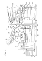
- Fig. 1 is an overall configuration diagram of a bookbinding system having an image forming apparatus A, a bookbinding apparatus B, a booklet storing apparatus C and an automatic document feeding apparatus DF.
- the image forming apparatus A is provided with an image forming section wherein a charging section 2, an image exposing section 3, a developing section 4, a transfer discharging section 5 and a cleaning section 6 are disposed in a periphery of a rotating image carrier 1.
- the image forming section charges a surface of the image carrier 1 through the charging section 2, thereafter forms a latent image by exposure scanning based on image data which is obtained by reading a document with a laser beam of the image exposing section 3. Then the latent image is developed by the developing section 4 to form a toner image on the surface of the image carrier 1.
- the sheet S fed from the sheet storing section 7A is conveyed to a transfer position in the image carrier 1.
- a transfer discharging section 5 discharges a surface of the sheet S and the sheet S is separated from the image carrier 1 and then conveyed through conveyance section 7B.
- the toner image on the sheet S is fixed on the sheet S through the fixing section 8 with heat and the sheet S is ejected from the image forming apparatus A through sheet ejection rollers 7C.
- the sheet S on which an image has been fixed through fixing section with heat is diverged from a sheet ejection pass through a conveyance pass changeover section 7D, and in reversal conveyance section 7E, the sheet is switched back and turned over. Then the sheet S is again conveyed to the image forming section and an image is formed on the reverse side of the sheet S.
- the sheet S ejected through the sheet ejection rollers 7C is fed to the bookbinding apparatus B.
- an operation section 9 is disposed on an upper part of the image forming apparatus A.
- the contents of the job to be executed in the bookbinding system are inputted by an user through the operation section 9.
- the bookbinding apparatus B is a case binding apparatus having a conveyance pass 10, a sheet ejection section 20, a reverse section 30, a sheet bundle storing section 40, an application section 50, a coversheet feeding section 60, a cutting section 70, and a booklet forming section 80.
- the bookbinding apparatus of the present invention can be adaptable to a gluing bookbinding apparatus, which simply binds a sheet bundle with an adhesive besides the case binding apparatus.
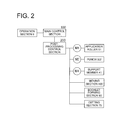
- Fig. 2 is a block diagram of a control system in the bookbinding system. Here main components are shown.
- a main control section 100 of the image forming apparatus A and the post-processing control section 200 of the bookbinding apparatus B are connected via serial communication sections 101 and 102 (see Fig. 1 ).
- the post-processing control section 200 controls each section of the bookbinding apparatus B.
- the post-processing control section 200 serves as a control section.
- the post processing control section 200 controls drive of each section described later so as to form a booklet. Namely, the post-processing control section 200 controls drive of a motor M1 to drive an application roller 51, a motor M2 to drive a punch 302 of a notch forming section 300, a motor M4 to drive a supporting member 41 to support the sheet bundle, a move section 400 to drive a notch forming section 300, a booklet forming section 80 and a cutting section 70.
- Fig. 3 is a central cross-sectional view of the bookbinding apparatus B.
- a conveyance pass changeover section Z2 located at an upstream side of the conveyance roller 11 in the sheet conveyance direction leads the sheet S ejected from the image forming apparatus A to either a conveyance pass a or a conveyance pass b.
- the sheet S led to the conveyance pass a is grasped and conveyed through the conveyance rollers 11 and 12 and the lead to either the ejection sheet 20 or the reversal section 30 through the conveyance pass changeover section Z1.
- the sheet S led to the conveyance pass b is grasped and conveyed through the conveyance rollers 14 to a booklet forming section 80 serving as a bookbinding section.
- the conveyance pass a is provided with a sheet sensor SEN to detect the sheet S conveyed through the conveyance pass a.
- the conveyance pass changeover section Z1 closes a conveyance pass c connected to the sheet bundle storing section 40 and open a conveyance pass d connected to the sheet ejection 20.
- the sheet S passed through the conveyance pass d connected to the sheet ejection section 20 is grasped by conveyance rollers 21 and conveyed upward then ejected to a fixed sheet ejection tray 22 at an upper most section of the apparatus through ejection rollers 22.
- the sheet S led to the conveyance pass c through the conveyance pass changeover section Z1 is grasped by the conveyance rollers 31, 32, 33 and 34 and stored in a predetermined position in the reversal section 30.
- the reversal section 30 is provided with an obliquely disposed sheet loading table 35, a registration member 36 to register a rear edge of the sheet and an aligning member 37 to align the sheet S in a sheet width direction and conveyance rollers 38.
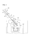
- Fig. 4 is a cross-sectional view showing an inclination state of a sheet accumulating section in the sheet bundle storing section 40.
- the sheet bundle storing section 40 is provided with a supporting member 41, a receiving board 42, a lateral aligning member 44 and a pressing member 45.
- the sheet S placed on the sheet loading table 35 in the reversal section 30, is grasped by the conveyance rollers 38 and ejected from an opening opened by tilting of the registration member 36 then conveyed obliquely downward.
- the sheet S is subsequently accumulated in the sheet bundle storing section 40.
- the sheet bundle storing section 40 is provided with a support member 41 having an oblique accumulation surface and a receiving board 42 which can tilt.
- a longitudinal aligning member 43 presses the rear edge of the sheet S in accordance with the size of the sheet S placed on the accumulating surface of the support member 41 so that the front edge of the sheet S comes in contact with the receiving board 42. Whereby the front edge of each sheet S is aligned.
- the sheet S subsequently ejected from the image forming apparatus A is conveyed through switch back in the reversal section 30 and accumulated in the sheet bundle storing section 40, whereby the sheet bundle Sa configured with a plurality of the sheets S are formed.
- the size of the sheet S and the number of sheets forming the sheet bundle Sa representing the setting conditions of the booklet formed by the bookbinding apparatus B is set through the operation section 9 of the image forming apparatus A or through an external equipment such as personal computer connected to the image forming apparatus A.
- the lateral aligning member 44 performs lateral alignment in the width direction of the sheet by pressing a side edge of the sheet S transferred from the reversal section 30 and stored in the sheet bundle storing section 40.
- the pressing member 45 presses the sheet bundle Sa accumulated in the sheet bundle storing section 40 in a thickness direction of the sheet bundle Sa so as to grasp the sheet bundle Sa.
- the pressing member 45 is operated by an unillustrated motor, so that the sheet bundle Sa is grasped by the supporting member 41 and the pressing member 45.
- Fig. 5 is a cross sectional view showing a vertical state of a sheet accumulation section in the sheet bundle storing section 40.
- the sheet supporting section 41 and the pressing section 45 gasping the sheet bundle Sa rotate centering around an axis 46 of the sheet bundle storing section 40 through a motor M4 and a drive section 47 so that the sheet bundle Sa becomes a vertical state from an oblique state.
- the application roller 51 of the application section 50 is separated from a lower surface of the sheet bundle Sa.
- the receiving board 42 rotates from a broken lines position to a solid line position in the figure by the unillustrated drive section.
- Fig. 6 is a cross-sectional view of the sheet bundle storing section 40, the application section 50, the coversheet feeding section 60, the cutting section 70 and the booklet forming section 80.
- the application section 50 is provided with the application roller 51, a drive section 52 to rotate the application roller 51, an adhesive container 53 to contain an adhesive N such as glue, a moving substance 54, movable from an initial position at back side of the bookbinding apparatus B to an application position at front side while supporting the adhesive container 53, a moving device 55 to reciprocate the moving substance 54 and a heating section 56 to heat the adhesive N contained in the adhesive container 53.
- an adhesive N such as glue
- a moving substance 54 movable from an initial position at back side of the bookbinding apparatus B to an application position at front side while supporting the adhesive container 53
- a moving device 55 to reciprocate the moving substance 54
- a heating section 56 to heat the adhesive N contained in the adhesive container 53.
- the moving substance 54 in the application section 50 moves in a direction parallel to a longitudinal direction of the lower surface of the sheet Sa vertically held by the supporting member 41 and the pressing member 45 through the drive section 47.
- the moving substance 54 starts moving from the initial position at the back side of the bookbinding apparatus B and moves along the moving device 55 then stops a predetermined position of the front side of the bookbinding apparatus B, and thereafter being driven backwards to return to the initial position.
- Fig. 7 is a perspective view of vicinities of the application section 50.
- the application roller 51 dipped in the adhesive N contained in the adhesive container 53 rotates through the motor M1 and the drive section 52. Through a forward travel or reciprocation of the moving substance 54, the application roller 51 applies the adhesive N on the lower surface of the sheet bundle Sa from the back side R to the front side F in the lower surface longitudinal direction of the sheet bundle Sa being held vertically.
- the adhesive N applied on a circumferential surface of the application roller 51 is restricted in its layer thickness by a restriction member 57.
- Fig. 6 shows, the coversheet K stored in a coversheet stacking section 61 of the coversheet feeding section 60 is separated and fed through the sheet feeding section 62, then grasped by the conveyance rollers 63, 64 and 65 to be conveyed to the booklet forming section 80.
- the cutting section 70 integrated with the booklet forming section 80 cuts the coversheet K in a predetermined length in a conveyance direction of the coversheet K through a rotary cutter configured with a rotation blade 71 and a fixed blade 72.
- the predetermined length is a length of two pieces of sheets S in the conveyance direction plus a length of the spine of the sheet bundle Sa.
- the predetermined length is set 450 mm which is two times the length of the short side of A4 sheet 210 mm plus the thickness of the sheet bundle Sa 30 mm. In that way, the coversheet K is cut (a overall length of the coversheet K before cutting is 450 mm or more).
- the predetermined length is set based on the length of the short side of the sheet and thickness of the sheet bundle.
- the control section sets the predetermined length of the coversheet K.
- the length of the coversheet K before cutting is determined in accordance with the maximum sheet number, and the coversheet K is stored in coversheet loading section 61 of the coversheet feeding section 60.
- the booklet forming section 80 is provided with conveyance rollers 81 and 82 to receive and convey the coversheet K fed from the coversheet feeding section 60 and to stop the coversheet K at a predetermined position, a pressure member 83 to press the coversheet K onto an adhesive application surface of the sheet bundle Sa, a movable housing 84 to support the conveyance rollers 81 and 82, and the pressure member 83, and a hoisting section 86 which enables the aligning section 85 and the movable housing 84 to movement vertically in up and down direction.
- the booklet forming section 80 and a booklet ejection belt 88 moves up and down integrally through the hoisting section 86.
- the aligning section 85 moves from an initial position in accordance with the size of the coversheet K and presses the coversheet K before the cutting process at the both sides in the width direction of the coversheet K to conduct widthwise aligning.
- the coversheets K of which skew is corrected by the widthwise aligning is switched back in an opposite direction to the input direction and conveyed to the cutting section 70 to be cut at the predetermined position.
- the aligning section 85 again moves from the initial position so as to align the coversheet K by pressing the both sides of the coversheet K in the width direction, and stops the coversheet K at the predetermined position. Thereafter, the aligning section 85 returns to the initial position in order not to interfere the bonding of the coversheet K and the sheet bundle Sa then the booklet forming section 80 ascends subsequently. When ascending, the coversheet K is supported at a predetermined position.
- the hosting section 86 moves the movable housing 84 upward by rotating the left and right belts. At the ascent position, a center area of the coversheet K loaded on the pressure member 83 is pressed onto the adhesive application surface of the sheet bundle Sa to be bonded. After completion of the application process of the adhesive on the sheet bundle Sa, the application section 50 is moved backward to be retracted.
- the coversheet folding section has a pair of bilaterally symmetric forming members 87A and 87B.
- the forming members 87A and 87B are detachable in the thickness direction of the sheet bundle Sa.
- the forming members 87A and 87B fold the coversheet K along side edges of the application surface of the adhesive of the sheet bundle Sa, and overlaps the front coversheet and rear coversheet onto the front surface and rear surface of the sheet bundle Sa respectively.
- the booklet forming section 80 descends by a predetermined amount through descent drive of the hoisting section 86, thereafter when the grasping of the grasping section is released, the booklet Sb falls and the lower surface of the spine comes to contact with the upper surface of the booklet ejection belt 88 then the booklet Sb is carried and ejected.
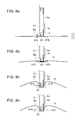
- Figs. 8a, 8b, 8c and 8d are cross-sectional views of the booklet forming section 80.
- Fig. 8a shows start of folding the coversheet
- Fig. 8b show folding of the coversheet is in mid-course
- Fig. 8c shows completion of folding the coversheet
- Fig. 8d shows releasing of compression for coversheet folding.
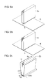
- Figs. 9a, 9b, and 9c are perspective views showing a forming process of the booklet Sb with the sheet bundle Sa and coversheet K.
- Fig. 9a is a perspective view of the coversheet K and the sheet bundle Sa before a bonding process of the coversheet
- Fig. 9b is a perspective view of the sheet bundle Sa to which the coversheet K is bonded
- Fig. 9c is a perspective view of the booklet Sb formed with the sheet bundle Sa by case binding with coversheet K.
- the forming members 87A and 87B are driven by the unillustrated drive section in an ascent state of the booklet forming section 80 shown in Figs. 8 .
- the coversheet K is deformed from the side edge sections of the adhesive application surface of the sheet bundle Sa while being grasped by the forming members 87A and 87B (see Fig. 8b ).
- the forming members 87A and 87B moves horizontally towards the adhesive application surface of the sheet bundle Sa and presses the both sides of the sheet bundle Sa for shaping, thereby forming the booklet Sa.
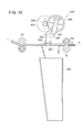
- Fig. 10 is a cross-sectional view of a notch device 300.
- the notch device 300 is provided with a die 301 firmly mounted at a sheet s conveyance pass, a punch 302 which ascends and fits the die 301, a drive section to ascend and descend the punch 302, and a trash box 303 to receive scrapes of the sheet S.
- a circumference surface of the punch 302 facing the die 301 fits an inner surface of a guide member 304 so as to be capable of ascending and descending.
- the drive section to ascend and descend the punch 302 is configured with a motor M2, a small gear 305 connected with the motor M2, a large gear 306 meshing with the small gear 305, a link 307 engaged with the large gear 306 at an eccentric position to be able to perform rocking motion and a connecting member 308 to connect the link 307 with an upper parts of the punch 302.
- the punch 302 is driven up and down via the small gear 305, the large gear 306, a link 307 and a connecting member 308.
- the punch 302 When the punch 302 is driven to be descent, the punch fits with the die 301, thereby forming the notch at an rear edge of the sheet S.
- Fig. 11 is a plane view of the sheet S on which holes and notches are formed.
- the notch Va As the shape of the notch Va, V-shape, and U-shape are used beside the semicircular shape.
- the notch Va can be formed by punches and dies used for ordinal sheet files.
- Number of the notches Va and holes H formed on the sheet S can be determined discretionary by adjusting number of the punches and dies.
- Two notches shown by Fig. 11a have a diameter of 6 mm and a center-to-center distance between holes of 80 mm
- three notches Va shown by Fig. 11b have the diameter of 6 mm and a center-to-center distance between holes of 108 mm.
- two circular shape holes h have a diameter of 6 mm and a center-to-center distance between holes of 80 mm
- three circular shape holes h shown by Fig. 11d have a diameter of 6 mm and a center-to-center distance between holes of 108 mm.
- the sheet S ejected from the image forming apparatus A passes through the notch device 300 without being processed and the adhesive application process is carried out.
- Fig. 12 is a front view of the notching device 300 and a moving section 400.
- the move section 400 moves notch forming sections 300A, 300B and 300C having the punches 302 and the dies 301 in left and right directions (a horizontal direction perpendicular to the sheet S conveyance direction) in Fig. 12 .
- the position of the notch Va formed on the sheet S is moved.
- a rack gear 404 moves in left and right directions in Fig. 12 via a gear train configured with gears 401, 402 and 403.
- the rack gear 404 With the rack gear 404, the notch forming sections 300A, 300B and 300C are engaged so that the notch forming sections 300A, 300B and 300C moves left and right directions by movement of the rack gear 404.
- the notch forming sections are three, number of the notch forming sections can be set discretionary according to the number of the notches and the holes to be formed on the sheet S.
- the notch forming apparatus is configured with a post-processing control section 200, the notch forming sections 300A, 300B and 300C, and the move section 400.
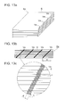
- Fig. 13a, 13b and 13c are a perspective view, a front view and a partial magnified view respectively showing the sheet bundle Sa having the notches Va.
- Fig. 13a is a perspective showing a sheet bundle Sa formed by accumulating the sheets S on which four notches Va are formed.
- Fig. 13b is a front view of the spine of the sheet bundle Sa, and
- Fig. 13c is a partial magnified view of the spine of the sheet bundle Sa.
- the adhesive N is applied to the spine of the sheet bundle Sa through the application section 50 shown in Fig. 5 .
- the adhesive N is applied to the spine and infiltrates into the notched Va so as to form a adhesive surface.
- Figs. 13b and 13c show, the positions of notches Va are shifted in the horizontal direction for each sheet, thus the groove configured with the notches Va forms a diagonal line.
- the adhesive can adhere at a shifted portion (portion c in Fig. 13c ) and the bonding force between the sheets S is enhanced.
- the potions of the notches can be shifted for every plurality of sheets (for example every two sheets) for simplifying the controls.
- the post-processing control section 200 controls operation of the move section 400, so that the notch forming sections 300A, 300B and 300C are moved in the horizontal direction for every sheet.
- Fig. 13b shows, to enhance the adhesive force between the sheets, it is effective that the positions of the notches Va are shifted so as to form the grooves configured with the notches Va diagonally.
- a space for the notch forming sections 300A, 300B and 300C for forming the notch Va to move in the horizontal direction has to be retained in the bookbinding apparatus B, thereby causing increase of size of the bookbinding apparatus B.
- the moving direction of the notch forming sections 300A, 300B and 300C is changed when the number of sheets reaches at a criterion number by sensing the number of sheets S on which the notches Va are formed in the bookbinding apparatus B.
- This aspect will be specifically described with reference to the Figs. 14 and 15 .
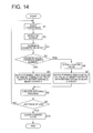
- Fig. 14 is a flow chart showing operation to shift the positions of the notches.
- a judging step (Steps S4 and S9) are executed in the post-processing control section 200 of the bookbinding apparatus B.
- the bookbinding apparatus B receives the sheet S from the image forming apparatus A and the sheet S is conveyed by the conveyance rollers 11 (Step S1). Then the sheet S is detected by a sheet sensor SEN disposed at the conveyance pass a in the bookbinding apparatus B (Step S2), and the post-processing control section 200 increments a counter value of a counter in the bookbinding apparatus B by one (Step S3) when a detection signal from the sheet detection sensor SEN is received. The count value is stored in a memory section (RAM) in the bookbinding apparatus B.
- RAM memory section
- the criterion number of the sheets is a value representing a timing at which the moving direction of the notch forming sections 300A, 300B and 300C is changed.
- the notch forming sections 300A, 300B and 300C are moved by a predetermined distance (for example, 0.5 mm) in accordance with information of a moving direction (for example, right direction in Fig. 12 (first direction))memorized in the memory section (RAM)(Step S5) without changing the moving direction of the notch forming sections 300A, 300B and 300C. Then notch forming process to form the notch Va on the sheet S is carried out by the punch 302 (Step S8).
- Step S6 the information for moving direction stored in the memory section (RAM) is modified, and in accordance with the modified information of the moving direction (for example, left direction (second direction) in Fig. 12 ) the notch forming sections 300Z, 300B and 300C are moved by a predetermined distance (for example, 0.5 mm)(Step S7), and the notch forming process is carried out by the punch 302 so as to from the notch Va on the sheet S (Step S8).
- a predetermined distance for example, 0.5 mm
- Step S9 whether or not a last page of the job to form the booklet is judged (Step S9), and if it is not the last page, the operation returns to Step S1.
- Step S7 the moving direction is changed thereafter operation of Steps S1, S2, S3, S4 S5 and S8 are repeated.
- the groove of notch Va formed on the spine of the sheet bundle Sa forms an inverted diagonal line in respect to that before the moving direction is changed.
- Step S4 in Fig. 14 the notch forming sections are moved for every single sheet, however, it can be moved for every plurality of the sheets (for example, every two sheets).
- the shape of the grooves formed by the notches Va becomes the shape in Fig. 15 for example.
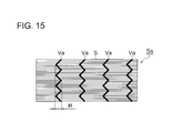
- the groove of the notches Va on the spine of the sheet bundle Sa forms so-called a zig-zag shape as Fig. 15 shows, and a distance H of the groove in the horizontal direction in Fig. 15 is short compare to the distance H of the groove in the horizontal direction in Fig. 13b .
- a moving range of the notch forming sections 300A, 300B and 300C is within the distance H of the groove in Fig. 15 , thus a large space in the horizontal direction is not necessary.
- adhesive force between the sheets can be enhanced.
- Fig. 15 while the grooves formed by the notches Va are four, the number of the grooves can be increased or decreased where necessary.
- the shifting distance of the notches defers a condition of booklet formed (adhesive force and appearance).
- Fig. 13c shows, the position of the notch Va is shifted by shifting amount t for every single sheet and the width of the groove formed by the notches Va is d in Fig. 13c .
- the width d of the groove formed by the notches Va increases, thus more adhesive infiltrates into the groove section and the adhesive force is enhanced.
- the groove from by the notched Va becomes visible faintly on the spine of the booklet formed, which deteriorates the appearance.
- an appropriate value of the width d of the groove formed by the notch Va is a value in a range of 0.5 mm to 1.5 mm, and the post-processing controls section 200 controls the movement of the notch forming sections 300A, 300B and 300C so that the width d of the groove is in the range thereof.
- the image forming apparatus A and the bookbinding apparatus B are separate units, however the apparatuses thereof can be integrated.
- the notch forming sections 300A, 300B and 300c are moved by the move section 400 in respect to the sheet S, however the sheet S can be moved in respect to the notch forming sections 300A, 300B and 300C so as to shift the positions of the notches.
- notch forming sections 300a, 300B and 300c are separate units, they can be integrated into one notch forming section having a plurality of the punches.
- the adhesive force between the sheets in the booklet is enhanced and increase of size of the apparatus can be avoided.
Landscapes
- Engineering & Computer Science (AREA)
- Mechanical Engineering (AREA)
- Life Sciences & Earth Sciences (AREA)
- Forests & Forestry (AREA)
- Physics & Mathematics (AREA)
- General Physics & Mathematics (AREA)
- Folding Of Thin Sheet-Like Materials, Special Discharging Devices, And Others (AREA)
Abstract
Description
- The present invention relates to a notch forming apparatus to form a notch at an edge of the sheet conveyed and a bookbinding apparatus and bookbinding system to form a booklet by binding a coversheet and a sheet bundle formed by bundling a plurality of sheets on which a notch having been formed.
- There have been suggested various technologies to form a booklet by binding a coversheet and the sheet bundle which are formed by bundling a plurality of sheets thereon having formed images. For example, in respect to a bookbinding system having an image forming apparatus such as a copying machine or a printer, the sheet bundle is automatically formed by bundling the plurality of the sheets on which the image is formed through an image forming apparatus, and the booklet is formed by binding the sheet bundle and the coversheet with an adhesive.
- A commonly-used procedure by the bookbinding system to form the booklet will be described as follow. First, the sheet bundle is formed by accumulating and aligning the plurality of the sheets having the formed image thereon. Next, the adhesive is applied on a spine of the sheet bundle having been accumulated and aligned. Then the sheet is conveyed and stopped at a predetermined position to bind the coversheet at the spine of the sheet bundle. Whereby, the booklet is formed by combining the plurality of the sheets and the coversheet.
- In the
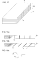
Figs. 16a and 16b , an example of a booklet configured with the sheet bundle and the coversheet is shown. -
Fig. 16a shows a state where the coversheet K has not yet been folded, andFig. 16b shows a state where the coversheet K has been folded. AsFig. 16a shows, the sheet bundle Sa on whose spine SB the adhesive has been applied is moved in the direction shown by an arrow so as to be bound with the coversheet K, then the sheet bundle Sa is wrapped by the coversheet K in a channel shape. In a final figure of the booklet, asFig. 16b shows, a side edge section SE of the sheet bundle Sa and a side edge section KE of the coversheet K are aligned. - Incidentally, if the adhesive is applied on the spine of the sheet bundle Sa as it is to the bind sheet bundle Sa and the coversheet K, an adhesion force between the sheet bundle Sa and the coversheet K cannot be ensured sufficiently, and as a result, there is occurred a problem that a part of sheets S drops from the booklet formed.
- To solve the aforesaid problem, as
Fig. 17 shows, there is a method that a notch Va is formed at the edge of the sheet S which represents the spine SB of the sheet bundle Sa so as to retain a space between the spine of the sheet bundle Sa and the coversheet K so that a large amount of the adhesive infiltrates between them, whereby the adhesive force between the sheet bundle Sa and the coversheet K is ensured. In the technology disclosed in Unexamined Japanese Patent Application Publication No.2007-62145 Fig. 17 is formed at the edge of the sheet S. - Patent Document 1: Unexamined Japanese Patent Application Publication No.
2007-62145 -
Fig. 18a is an explanatory diagram showing a groove shape of the notch Va formed at the spine SB of the sheet bundle Sa and indicating a view the spine SB of the sheet Sa seen from a X direction inFig. 17 . - A position of the notch Va formed on the sheet bundle Sa can be varied. For example, as
Fig. 18a shows, the position of the notch Va on each sheet S is not changed and the notch Va is formed at the same position on each sheet whereby the groove of the notches Va are formed in an vertical line. In case of a configuration shown byFig. 8a , the space between the spine SB of sheet bundle Sa can be retained and the large amount of the adhesive can be infiltrated between them. However, the adhesive force between the sheets cannot be ensured and a part of sheets S may be fallen off from the booklet formed. - Thus, there is a configuration that the positions of the notches Va are displaced for every sheets so that the grooves of the notches Va form a diagonal line. Whereby by displacing the positions of the notches Va gradually, as
Fig. 18c shows, the adhesive intermediates in a portion representing a displacement amount t of the notches Va, and the adhesive force between sheets can be ensured. - However, as
Fig. 18b shows, in order to displace the positions of the notches Va consistently in one direction, a space to shift the device to form the notch Va on the sheet S or the sheets S in a direction a or a direction b has to be retained inside the apparatus, resulting in that increasing of the apparatus size is incurred. For example, given that the displacement amount t of the notch Va for each sheet is 0.5 mm, if the number of the sheets Sa is 300, a total displacement amount will be 150 mm, thus the space has to be retained in the directions a or b for that amount. - The aforesaid problems are solved by the following structures.
- 1. A notch forming apparatus, having:
- a notch forming section to form a notch at a edge of a sheet;
- a move section to move a position of the notch formed through the notch forming section on the sheet; and
- a control section to control at least the move section so that the position of the notch is moved in a first direction every time the notch is formed on the single sheet or a plurality of the sheets, and when number of sheets on which the notch is formed reaches at a criterion number, the position of the notch is moved in a second direction opposite to the first direction.
- 2. A bookbinding apparatus, having;
the notch forming apparatus ofclaim 1, and a bookbinding section to form a sheet bundle by accumulating the sheets on which the notch is formed though the notch forming apparatus and to form a booklet by biding the sheet bundle with an adhesive. - 3. A bookbinding system, having;
an image forming apparatus to form an image on a sheet; and the bookbinding apparatus ofclaim 4 to form the booklet using the sheet on which an image is formed by the image forming apparatus. -
-
Fig. 1 is an overall configuration diagram of a bookbinding system having an image forming apparatus, a bookbinding apparatus, a booklet storing apparatus and an automatic document feeding apparatus. -
Fig. 2 is a block diagram of a control system in a bookbinding system. -
Fig. 3 is a central cross-sectional view of a bookbinding apparatus. -
Fig. 4 is a cross-sectional view showing an inclination state of a sheet accumulating section in a sheet bundle storing section. -
Fig. 5 is a cross-sectional view showing a vertical state of a sheet accumulating section in a sheet bundle string section. -
Fig. 6 is a cross-sectional view showing a sheet bundle storing section, application section, coversheet feeding section, cutting section, and booklet forming section. -
Fig. 7 is a perspective view of a vicinity of an application section. -
Figs. 8a, 8b, 8c and 8d are cross-sectional views of a booklet forming section and a sheet bundle indicating a folding process of a coversheet. -
Figs. 9a, 9b and 9c are perspective views showing a forming process of a booklet using a sheet bundle and a coversheet. -
Fig. 10 is a cross-sectional view of a notch section. -
Figs. 11a, 11b, 11c and 11d are plane views of sheets on which notches and punch holes have been formed. -
Fig. 12 is a front view of a notch section and a moving section. -
Figs. 13a, 13b and 13c are a perspective view, a front view of and a partial magnified view of a sheet bundle having notches thereon. -
Fig. 14 is a flow chart indicating operation to change a position of a notch. -
Fig. 15 is a front view of a spine of a sheet bundle. -
Figs. 16a and 16b are perspective views of a booklet configured with a sheet bundle and a coversheet. -
Fig. 17 is a perspective view showing a sheet bundle having formed notches thereon. -
Figs. 18a, 18b and 18c are explanatory diagrams indicating groove shapes of notches formed on spines of sheet bundles. -
Fig. 1 is an overall configuration diagram of a bookbinding system having an image forming apparatus A, a bookbinding apparatus B, a booklet storing apparatus C and an automatic document feeding apparatus DF. - The image forming apparatus A is provided with an image forming section wherein a
charging section 2, animage exposing section 3, a developingsection 4, atransfer discharging section 5 and acleaning section 6 are disposed in a periphery of arotating image carrier 1. The image forming section charges a surface of theimage carrier 1 through thecharging section 2, thereafter forms a latent image by exposure scanning based on image data which is obtained by reading a document with a laser beam of theimage exposing section 3. Then the latent image is developed by the developingsection 4 to form a toner image on the surface of theimage carrier 1. - The sheet S fed from the
sheet storing section 7A is conveyed to a transfer position in theimage carrier 1. After transferring the toner image onto the sheet S at the transfer position, atransfer discharging section 5 discharges a surface of the sheet S and the sheet S is separated from theimage carrier 1 and then conveyed throughconveyance section 7B. Thereafter, the toner image on the sheet S is fixed on the sheet S through the fixingsection 8 with heat and the sheet S is ejected from the image forming apparatus A throughsheet ejection rollers 7C. - In case images are formed on both sides of the Sheet S, the sheet S on which an image has been fixed through fixing section with heat is diverged from a sheet ejection pass through a conveyance
pass changeover section 7D, and inreversal conveyance section 7E, the sheet is switched back and turned over. Then the sheet S is again conveyed to the image forming section and an image is formed on the reverse side of the sheet S. The sheet S ejected through thesheet ejection rollers 7C is fed to the bookbinding apparatus B. - On an upper part of the image forming apparatus A, an
operation section 9 is disposed. The contents of the job to be executed in the bookbinding system are inputted by an user through theoperation section 9. - As
Fig. 1 shows the bookbinding apparatus B is a case binding apparatus having aconveyance pass 10, asheet ejection section 20, areverse section 30, a sheetbundle storing section 40, anapplication section 50, acoversheet feeding section 60, acutting section 70, and abooklet forming section 80. Incidentally, the bookbinding apparatus of the present invention can be adaptable to a gluing bookbinding apparatus, which simply binds a sheet bundle with an adhesive besides the case binding apparatus. -
Fig. 2 is a block diagram of a control system in the bookbinding system. Here main components are shown. Amain control section 100 of the image forming apparatus A and thepost-processing control section 200 of the bookbinding apparatus B are connected viaserial communication sections 101 and 102 (seeFig. 1 ). By an instruction of themain control section 100, thepost-processing control section 200 controls each section of the bookbinding apparatus B. Meanwhile, in the present embodiment, thepost-processing control section 200 serves as a control section. - The post
processing control section 200 controls drive of each section described later so as to form a booklet. Namely, thepost-processing control section 200 controls drive of a motor M1 to drive anapplication roller 51, a motor M2 to drive apunch 302 of anotch forming section 300, a motor M4 to drive a supportingmember 41 to support the sheet bundle, amove section 400 to drive anotch forming section 300, abooklet forming section 80 and acutting section 70. -
Fig. 3 is a central cross-sectional view of the bookbinding apparatus B. A conveyance pass changeover section Z2 located at an upstream side of theconveyance roller 11 in the sheet conveyance direction leads the sheet S ejected from the image forming apparatus A to either a conveyance pass a or a conveyance pass b. The sheet S led to the conveyance pass a is grasped and conveyed through theconveyance rollers ejection sheet 20 or thereversal section 30 through the conveyance pass changeover section Z1. The sheet S led to the conveyance pass b is grasped and conveyed through theconveyance rollers 14 to abooklet forming section 80 serving as a bookbinding section. The conveyance pass a is provided with a sheet sensor SEN to detect the sheet S conveyed through the conveyance pass a. - To eject the sheet S to the
sheet ejection section 20, the conveyance pass changeover section Z1 closes a conveyance pass c connected to the sheetbundle storing section 40 and open a conveyance pass d connected to thesheet ejection 20. The sheet S passed through the conveyance pass d connected to thesheet ejection section 20 is grasped byconveyance rollers 21 and conveyed upward then ejected to a fixedsheet ejection tray 22 at an upper most section of the apparatus throughejection rollers 22. - The sheet S led to the conveyance pass c through the conveyance pass changeover section Z1 is grasped by the
conveyance rollers reversal section 30. Thereversal section 30 is provided with an obliquely disposed sheet loading table 35, aregistration member 36 to register a rear edge of the sheet and an aligningmember 37 to align the sheet S in a sheet width direction andconveyance rollers 38. -
Fig. 4 is a cross-sectional view showing an inclination state of a sheet accumulating section in the sheetbundle storing section 40. The sheetbundle storing section 40 is provided with a supportingmember 41, a receivingboard 42, alateral aligning member 44 and a pressingmember 45. - The sheet S, placed on the sheet loading table 35 in the
reversal section 30, is grasped by theconveyance rollers 38 and ejected from an opening opened by tilting of theregistration member 36 then conveyed obliquely downward. The sheet S is subsequently accumulated in the sheetbundle storing section 40. - The sheet
bundle storing section 40 is provided with asupport member 41 having an oblique accumulation surface and a receivingboard 42 which can tilt. The sheet S fell down from thereversal section 30 slips off the accumulation surface of theoblique support member 41 then a front edged of the sheet S comes to contact with the receivingboard 42 an stops, whereby the sheet S is supported in a oblique state. A longitudinal aligningmember 43 presses the rear edge of the sheet S in accordance with the size of the sheet S placed on the accumulating surface of thesupport member 41 so that the front edge of the sheet S comes in contact with the receivingboard 42. Whereby the front edge of each sheet S is aligned. The sheet S subsequently ejected from the image forming apparatus A is conveyed through switch back in thereversal section 30 and accumulated in the sheetbundle storing section 40, whereby the sheet bundle Sa configured with a plurality of the sheets S are formed. - The size of the sheet S and the number of sheets forming the sheet bundle Sa representing the setting conditions of the booklet formed by the bookbinding apparatus B is set through the
operation section 9 of the image forming apparatus A or through an external equipment such as personal computer connected to the image forming apparatus A. - The
lateral aligning member 44 performs lateral alignment in the width direction of the sheet by pressing a side edge of the sheet S transferred from thereversal section 30 and stored in the sheetbundle storing section 40. - The pressing
member 45 presses the sheet bundle Sa accumulated in the sheetbundle storing section 40 in a thickness direction of the sheet bundle Sa so as to grasp the sheet bundle Sa. At a stage where the set numbers of the sheets S are accumulated in the sheetbundle storing section 40, the pressingmember 45 is operated by an unillustrated motor, so that the sheet bundle Sa is grasped by the supportingmember 41 and the pressingmember 45. -
Fig. 5 is a cross sectional view showing a vertical state of a sheet accumulation section in the sheetbundle storing section 40. - The
sheet supporting section 41 and thepressing section 45 gasping the sheet bundle Sa rotate centering around anaxis 46 of the sheetbundle storing section 40 through a motor M4 and adrive section 47 so that the sheet bundle Sa becomes a vertical state from an oblique state. In the above state, theapplication roller 51 of theapplication section 50 is separated from a lower surface of the sheet bundle Sa. Also, in a state where the sheet bundle Sa is grasped by the supportingmember 41 and the pressingmember 45, the receivingboard 42 rotates from a broken lines position to a solid line position in the figure by the unillustrated drive section. -
Fig. 6 is a cross-sectional view of the sheetbundle storing section 40, theapplication section 50, thecoversheet feeding section 60, the cuttingsection 70 and thebooklet forming section 80. - The
application section 50 is provided with theapplication roller 51, adrive section 52 to rotate theapplication roller 51, anadhesive container 53 to contain an adhesive N such as glue, a movingsubstance 54, movable from an initial position at back side of the bookbinding apparatus B to an application position at front side while supporting theadhesive container 53, a movingdevice 55 to reciprocate the movingsubstance 54 and aheating section 56 to heat the adhesive N contained in theadhesive container 53. - The moving
substance 54 in theapplication section 50 moves in a direction parallel to a longitudinal direction of the lower surface of the sheet Sa vertically held by the supportingmember 41 and the pressingmember 45 through thedrive section 47. - The moving
substance 54 starts moving from the initial position at the back side of the bookbinding apparatus B and moves along the movingdevice 55 then stops a predetermined position of the front side of the bookbinding apparatus B, and thereafter being driven backwards to return to the initial position. -
Fig. 7 is a perspective view of vicinities of theapplication section 50. - The
application roller 51 dipped in the adhesive N contained in theadhesive container 53 rotates through the motor M1 and thedrive section 52. Through a forward travel or reciprocation of the movingsubstance 54, theapplication roller 51 applies the adhesive N on the lower surface of the sheet bundle Sa from the back side R to the front side F in the lower surface longitudinal direction of the sheet bundle Sa being held vertically. - The adhesive N applied on a circumferential surface of the
application roller 51 is restricted in its layer thickness by arestriction member 57. - As
Fig. 6 shows, the coversheet K stored in acoversheet stacking section 61 of thecoversheet feeding section 60 is separated and fed through thesheet feeding section 62, then grasped by theconveyance rollers booklet forming section 80. - Above the
coversheet feeding section 60 in the figure, and on the right-hand side of thebooklet forming section 80, the cuttingsection 70 integrated with thebooklet forming section 80 cuts the coversheet K in a predetermined length in a conveyance direction of the coversheet K through a rotary cutter configured with arotation blade 71 and a fixedblade 72. - The predetermined length is a length of two pieces of sheets S in the conveyance direction plus a length of the spine of the sheet bundle Sa. For example, in case the case bookbinding is carried out by bonding the coversheet K on the spine of the sheet bundle Sa configured with the sheet S in A4 size, given that a maximum sheet number of the sheet bundle Sa is 300 pieces and the thickness thereof is about 30 mm, the predetermined length is set 450 mm which is two times the length of the short side of
A4 sheet 210 mm plus the thickness of thesheet bundle Sa 30 mm. In that way, the coversheet K is cut (a overall length of the coversheet K before cutting is 450 mm or more). - In case each of sheets having A5 size, B5 size and 8.5 x 11 inch (one inch is 25.4 mm) is processed by the case bookbinding to form a booklet, the predetermined length is set based on the length of the short side of the sheet and thickness of the sheet bundle.
- When the sheet size, the sheet number and the sheet thickness is set or detected through the
operation section 9 of the image forming apparatus A or the external equipment, the control section sets the predetermined length of the coversheet K. The length of the coversheet K before cutting is determined in accordance with the maximum sheet number, and the coversheet K is stored incoversheet loading section 61 of thecoversheet feeding section 60. - The
booklet forming section 80 is provided withconveyance rollers coversheet feeding section 60 and to stop the coversheet K at a predetermined position, apressure member 83 to press the coversheet K onto an adhesive application surface of the sheet bundle Sa, amovable housing 84 to support theconveyance rollers pressure member 83, and ahoisting section 86 which enables the aligningsection 85 and themovable housing 84 to movement vertically in up and down direction. - The
booklet forming section 80 and abooklet ejection belt 88 moves up and down integrally through thehoisting section 86. When thebooklet forming section 80 stops at a descent position to input the sheet K, the aligningsection 85 moves from an initial position in accordance with the size of the coversheet K and presses the coversheet K before the cutting process at the both sides in the width direction of the coversheet K to conduct widthwise aligning. The coversheets K of which skew is corrected by the widthwise aligning is switched back in an opposite direction to the input direction and conveyed to thecutting section 70 to be cut at the predetermined position. - Also, before the
booklet forming section 80 bonds the coversheet K after cutting and the spine of the sheet bundle Sa by the adhesive at the descent position, the aligningsection 85 again moves from the initial position so as to align the coversheet K by pressing the both sides of the coversheet K in the width direction, and stops the coversheet K at the predetermined position. Thereafter, the aligningsection 85 returns to the initial position in order not to interfere the bonding of the coversheet K and the sheet bundle Sa then thebooklet forming section 80 ascends subsequently. When ascending, the coversheet K is supported at a predetermined position. - Therefore, improvement of a cutting accuracy and a positioning accuracy of the sheet bundle Sa and the coversheet K, and enhancement of simplification of the configuration can be attained through the aligning
section 85 disposed on the hoistingbooklet forming section 80 to carry out positioning of the coversheet K before and after cutting by cuttingsection 70 in a coversheet width direction. - The hosting
section 86 moves themovable housing 84 upward by rotating the left and right belts. At the ascent position, a center area of the coversheet K loaded on thepressure member 83 is pressed onto the adhesive application surface of the sheet bundle Sa to be bonded. After completion of the application process of the adhesive on the sheet bundle Sa, theapplication section 50 is moved backward to be retracted. - On the upper part of the
booklet forming section 80, a coversheet folding section is equipped. The coversheet folding section has a pair of bilaterally symmetric formingmembers members members - After completion of the folding process of the coversheet K, the
booklet forming section 80 descends by a predetermined amount through descent drive of thehoisting section 86, thereafter when the grasping of the grasping section is released, the booklet Sb falls and the lower surface of the spine comes to contact with the upper surface of thebooklet ejection belt 88 then the booklet Sb is carried and ejected. -
Figs. 8a, 8b, 8c and 8d are cross-sectional views of thebooklet forming section 80.Fig. 8a shows start of folding the coversheet,Fig. 8b show folding of the coversheet is in mid-course,Fig. 8c shows completion of folding the coversheet andFig. 8d shows releasing of compression for coversheet folding. -
Figs. 9a, 9b, and 9c are perspective views showing a forming process of the booklet Sb with the sheet bundle Sa and coversheet K.Fig. 9a is a perspective view of the coversheet K and the sheet bundle Sa before a bonding process of the coversheet,Fig. 9b is a perspective view of the sheet bundle Sa to which the coversheet K is bonded andFig. 9c is a perspective view of the booklet Sb formed with the sheet bundle Sa by case binding with coversheet K. - After the coversheet K is bonded to the sheet bundle Sa on which the adhesive N is applied, the forming
members booklet forming section 80 shown inFigs. 8 . The coversheet K is deformed from the side edge sections of the adhesive application surface of the sheet bundle Sa while being grasped by the formingmembers Fig. 8b ). Thereafter, the formingmembers -
Fig. 10 is a cross-sectional view of anotch device 300. Thenotch device 300 is provided with adie 301 firmly mounted at a sheet s conveyance pass, apunch 302 which ascends and fits thedie 301, a drive section to ascend and descend thepunch 302, and atrash box 303 to receive scrapes of the sheet S. - A circumference surface of the
punch 302 facing thedie 301 fits an inner surface of aguide member 304 so as to be capable of ascending and descending. The drive section to ascend and descend thepunch 302 is configured with a motor M2, asmall gear 305 connected with the motor M2, alarge gear 306 meshing with thesmall gear 305, alink 307 engaged with thelarge gear 306 at an eccentric position to be able to perform rocking motion and a connectingmember 308 to connect thelink 307 with an upper parts of thepunch 302. By driving the motor M2, thepunch 302 is driven up and down via thesmall gear 305, thelarge gear 306, alink 307 and a connectingmember 308. When thepunch 302 is driven to be descent, the punch fits with thedie 301, thereby forming the notch at an rear edge of the sheet S. -
Fig. 11 is a plane view of the sheet S on which holes and notches are formed. - As the shape of the notch Va, V-shape, and U-shape are used beside the semicircular shape. For example, the notch Va can be formed by punches and dies used for ordinal sheet files.
- Number of the notches Va and holes H formed on the sheet S can be determined discretionary by adjusting number of the punches and dies. Two notches shown by
Fig. 11a have a diameter of 6 mm and a center-to-center distance between holes of 80 mm, and three notches Va shown byFig. 11b have the diameter of 6 mm and a center-to-center distance between holes of 108 mm. Also two circular shape holes h have a diameter of 6 mm and a center-to-center distance between holes of 80 mm, and three circular shape holes h shown byFig. 11d have a diameter of 6 mm and a center-to-center distance between holes of 108 mm. - If the perforation process and notch process is not set in the
operation section 9 of the image forming apparatus A, the sheet S ejected from the image forming apparatus A passes through thenotch device 300 without being processed and the adhesive application process is carried out. - In the
control section 9, if the notch process to form the notch is set, after the rear edge of the sheet s is detected by a sensor PS (seeFig. 10 ), number of pulses, which is larger than number of pulses in case holes h are formed, is counted then the sheet S is conveyed and stopped. Thereafter notches Va are formed at a vicinity of the rear edge section of the sheets (seeFig. 11a and 11b ). - In the
control section 9, if the perforation process to form circular holes h is set, after detecting passage of the rear edge of the sheet S conveyed through theconveyance rollers Fig. 10 orFig. 12 ), the number of pluses is counted, then drive of a sheet conveyance motor is ceased to stop advancement of the sheet S. At the stop position, the holes h are formed at the vicinity of the rear edge of the sheet S (seeFigs. 11c and d ). -
Fig. 12 is a front view of the notchingdevice 300 and a movingsection 400. - The
move section 400 moves notch formingsections punches 302 and the dies 301 in left and right directions (a horizontal direction perpendicular to the sheet S conveyance direction) inFig. 12 . By moving thenotch forming sections - By driving the motor M3, a
rack gear 404 moves in left and right directions inFig. 12 via a gear train configured withgears rack gear 404, thenotch forming sections notch forming sections rack gear 404. Incidentally, inFig. 12 , while the notch forming sections are three, number of the notch forming sections can be set discretionary according to the number of the notches and the holes to be formed on the sheet S. Also, in the present embodiment, the notch forming apparatus is configured with apost-processing control section 200, thenotch forming sections move section 400. -
Fig. 13a, 13b and 13c are a perspective view, a front view and a partial magnified view respectively showing the sheet bundle Sa having the notches Va.Fig. 13a is a perspective showing a sheet bundle Sa formed by accumulating the sheets S on which four notches Va are formed.Fig. 13b is a front view of the spine of the sheet bundle Sa, andFig. 13c is a partial magnified view of the spine of the sheet bundle Sa. - On the spine of the sheet bundle Sa, four (the number is discretional) notches Va are formed for each sheet S. The four notches Va are arranged substantially at equal distances to form soaking surfaces of the adhesive. In this state, the adhesive N is applied to the spine of the sheet bundle Sa through the
application section 50 shown inFig. 5 . The adhesive N is applied to the spine and infiltrates into the notched Va so as to form a adhesive surface. - As above, by infiltration of the adhesive N into the notches Va formed on the spine of the sheet bundle Sa, the adhesive force of the spine of the sheet bundle Sa is enhanced, and missing page, due to falling off of insufficiently bonded sheet S by opening the booklet formed by bonding the coversheet K, can be avoided.
- Also, as
Figs. 13b and 13c show, the positions of notches Va are shifted in the horizontal direction for each sheet, thus the groove configured with the notches Va forms a diagonal line. As above, by moving the positions of the notches Va gradually, the adhesive can adhere at a shifted portion (portion c inFig. 13c ) and the bonding force between the sheets S is enhanced. Meanwhile, by shifting the position of the notches Va for each sheet, a strong adhesive force can be obtained, however the potions of the notches can be shifted for every plurality of sheets (for example every two sheets) for simplifying the controls. - As
Fig. 13 shows, to shift the position of the notch Va for every sheet in the horizontal direction, thepost-processing control section 200 controls operation of themove section 400, so that thenotch forming sections - Incidentally, as
Fig. 13b shows, to enhance the adhesive force between the sheets, it is effective that the positions of the notches Va are shifted so as to form the grooves configured with the notches Va diagonally. However, to shift the positions of the notches Va in the same direction consistently, a space for thenotch forming sections Fig. 12 , left and right directions) has to be retained in the bookbinding apparatus B, thereby causing increase of size of the bookbinding apparatus B. Thus, to solve the above problem, the moving direction of thenotch forming sections Figs. 14 and15 . -
Fig. 14 is a flow chart showing operation to shift the positions of the notches. A judging step (Steps S4 and S9) are executed in thepost-processing control section 200 of the bookbinding apparatus B. - First, when a job to form the booklet starts in the bookbinding system, the bookbinding apparatus B receives the sheet S from the image forming apparatus A and the sheet S is conveyed by the conveyance rollers 11 (Step S1). Then the sheet S is detected by a sheet sensor SEN disposed at the conveyance pass a in the bookbinding apparatus B (Step S2), and the
post-processing control section 200 increments a counter value of a counter in the bookbinding apparatus B by one (Step S3) when a detection signal from the sheet detection sensor SEN is received. The count value is stored in a memory section (RAM) in the bookbinding apparatus B. - When the count value is incremented by one in Step S3, whether or not the count value reaches at the value of the criterion number of the sheets is judged (Step S4). The criterion number of the sheets is a value representing a timing at which the moving direction of the
notch forming sections - In case that the count value has not been reached at the criterion number of the sheets (Step S4; No), it is not necessary to change the direction of shifting the positions of the notches Va. Thus the
notch forming sections Fig. 12 (first direction))memorized in the memory section (RAM)(Step S5) without changing the moving direction of thenotch forming sections - On the other hand, if it is judged that the count value is reached at the criterion number of the sheets (Step S4; Yes), it is necessary to change the shifting direction of the positions of the notches, and first, the counter value of the counter is cleared (Step S6). Then the information for moving direction stored in the memory section (RAM) is modified, and in accordance with the modified information of the moving direction (for example, left direction (second direction) in
Fig. 12 ) thenotch forming sections punch 302 so as to from the notch Va on the sheet S (Step S8). After the notch forming process, whether or not a last page of the job to form the booklet is judged (Step S9), and if it is not the last page, the operation returns to Step S1. In Step S7, the moving direction is changed thereafter operation of Steps S1, S2, S3, S4 S5 and S8 are repeated. Whereby the groove of notch Va formed on the spine of the sheet bundle Sa forms an inverted diagonal line in respect to that before the moving direction is changed. Incidentally, in Step S4 inFig. 14 the notch forming sections are moved for every single sheet, however, it can be moved for every plurality of the sheets (for example, every two sheets). - By forming the notches Va on the spine of the sheet bundle Sa based on the operation shown in
Fig. 14 , the shape of the grooves formed by the notches Va becomes the shape inFig. 15 for example. The groove of the notches Va on the spine of the sheet bundle Sa forms so-called a zig-zag shape asFig. 15 shows, and a distance H of the groove in the horizontal direction inFig. 15 is short compare to the distance H of the groove in the horizontal direction inFig. 13b . Namely, a moving range of thenotch forming sections Fig. 15 , thus a large space in the horizontal direction is not necessary. Also, since the positions of the notches are shifted, adhesive force between the sheets can be enhanced. Incidentally, inFig. 15 , while the grooves formed by the notches Va are four, the number of the grooves can be increased or decreased where necessary. - As described in
Fig. 14 andFig. 15 , when the number of sheet S on which the notches Va are formed reaches at the criterion number of the sheets, by changing the shifting direction of the position of the notches, the adhesive force between the sheets in the booklet is enhanced and increase of size of the apparatus can be avoided. - The shifting distance of the notches defers a condition of booklet formed (adhesive force and appearance). As
Fig. 13c shows, the position of the notch Va is shifted by shifting amount t for every single sheet and the width of the groove formed by the notches Va is d inFig. 13c . - As the shifting amount t decreases, the width d of the groove formed by the notches Va increases, thus more adhesive infiltrates into the groove section and the adhesive force is enhanced. However, the groove from by the notched Va becomes visible faintly on the spine of the booklet formed, which deteriorates the appearance.
- On the other hand, as the shifting amount t increases, the width d of the groove formed by the notch Va decreases, thus the groove from by the notched Va does not become visible, however the adhesive force is deteriorated since the less adhesive infiltrates into the groove.
- Therefore, in the groove shown by
Fig. 13 , an appropriate value (appropriate value in aspects of appearance and adhesive force) of the width d of the groove formed by the notch Va was studied through an experiment. In the experiment, the width d of the groove formed by the notch Va is changed from 0.3 mm to 1.7 mm by 0.1 mm thus a total of 15 kids of the widths d of grooves were studied. - First, in respect to the appearance of the booklet in the aspect that the grooves formed by the notches Va are not visible, a preferable result was obtained with the width d within a range from 0.3 mm to 1.5 mm. Also, in respect to ensuring the adhesive force by infiltrating the adhesive into the groove section, a preferable result was obtained with the width d within a range of 0.5 mm to 1.7 mm.
- Therefore, in both aspects to the appearance and to the adhesive force, an appropriate value of the width d of the groove formed by the notch Va is a value in a range of 0.5 mm to 1.5 mm, and the
post-processing controls section 200 controls the movement of thenotch forming sections - Incidentally, the present invention is not limited to the embodiment thereof and it is to be understood that changes and variations may be made without departing from the spirit or scope of the appended claims.
- In the bookbinding system show by
Fig. 1 , the image forming apparatus A and the bookbinding apparatus B are separate units, however the apparatuses thereof can be integrated. - Also, in the structure shown by
Fig. 12 , thenotch forming sections move section 400 in respect to the sheet S, however the sheet S can be moved in respect to thenotch forming sections - Also, while the
notch forming sections 300a, 300B and 300c are separate units, they can be integrated into one notch forming section having a plurality of the punches. - According to the notch forming device, the bookbinding apparatus and the bookbinding system, the adhesive force between the sheets in the booklet is enhanced and increase of size of the apparatus can be avoided.
Claims (5)
- A notch forming apparatus, comprising:a notch forming section to form a notch at an edge of a sheet;a move section to move a position of the notch to be formed through the notch forming section on the sheet; anda control section to control at least the move section so that the position of the notch to be formed is moved in a first direction every time the notch is formed on the single sheet or a plurality of the sheets, and when number of sheets on which the notch is formed reaches at a criterion number, the position of the notch to be formed is moved in a second direction opposite to the first direction.
- The notch forming apparatus of claim 1, wherein the move section moves the notch forming section to move the position of the notch to be formed.
- The notch forming apparatus of claim 1 or 2, wherein a sheet bundle is formed by biding a plurality of the sheets on which the notches are formed by the notch forming section, and the control section controls at least the move section so that a width of a groove formed by the notches on the sheet bundle is not less than 0.5 mm and not more than 1.5 mm.
- A bookbinding apparatus, comprising;
the notch forming apparatus of any one of claims 1 to 3, and
a bookbinding section to form a sheet bundle by accumulating the sheets on which the notch is formed though the notch forming apparatus and to form a booklet by binding the sheet bundle thereof with an adhesive. - A bookbinding system, comprising;
an image forming apparatus to form an image on a sheet; and
the bookbinding apparatus of claim 4 to form the booklet using the sheet on which an image is formed by the image forming apparatus.
Applications Claiming Priority (1)
| Application Number | Priority Date | Filing Date | Title |
|---|---|---|---|
| JP2008131697A JP2009279776A (en) | 2008-05-20 | 2008-05-20 | Notch forming apparatus and bookbinding apparatus/system |
Publications (3)
| Publication Number | Publication Date |
|---|---|
| EP2123411A2 true EP2123411A2 (en) | 2009-11-25 |
| EP2123411A3 EP2123411A3 (en) | 2010-06-23 |
| EP2123411B1 EP2123411B1 (en) | 2011-09-28 |
Family
ID=40929632
Family Applications (1)
| Application Number | Title | Priority Date | Filing Date |
|---|---|---|---|
| EP09160019A Not-in-force EP2123411B1 (en) | 2008-05-20 | 2009-05-12 | Notch forming apparatus, bookbinding apparatus and bookbinding system |
Country Status (5)
| Country | Link |
|---|---|
| US (1) | US20090290959A1 (en) |
| EP (1) | EP2123411B1 (en) |
| JP (1) | JP2009279776A (en) |
| CN (1) | CN101585271B (en) |
| AT (1) | ATE526129T1 (en) |
Families Citing this family (5)
| Publication number | Priority date | Publication date | Assignee | Title |
|---|---|---|---|---|
| JP5169524B2 (en) * | 2008-06-20 | 2013-03-27 | コニカミノルタビジネステクノロジーズ株式会社 | Notch forming device, bookbinding device and bookbinding system |
| JP4609538B2 (en) * | 2008-07-01 | 2011-01-12 | コニカミノルタビジネステクノロジーズ株式会社 | Notch forming device, bookbinding device and bookbinding system |
| CN102744999B (en) * | 2012-07-26 | 2014-11-26 | 安徽新华印刷股份有限公司 | Bookblock slotting device of bookbinding machine |
| JP5890505B1 (en) * | 2014-10-14 | 2016-03-22 | ファナック株式会社 | Cutting apparatus, robot, and robot system for cutting a substrate |
| JP7600736B2 (en) * | 2021-02-15 | 2024-12-17 | セイコーエプソン株式会社 | Aftertreatment Device |
Citations (1)
| Publication number | Priority date | Publication date | Assignee | Title |
|---|---|---|---|---|
| JP2007062145A (en) | 2005-08-31 | 2007-03-15 | Konica Minolta Business Technologies Inc | Bookbinding equipment and image forming system |
Family Cites Families (6)
| Publication number | Priority date | Publication date | Assignee | Title |
|---|---|---|---|---|
| US4741236A (en) * | 1986-08-18 | 1988-05-03 | Harris Graphics Corporation | Apparatus for notching the back of a book |
| US5542800A (en) * | 1995-04-03 | 1996-08-06 | R. R. Donnelley & Sons Company | Method and system for binding a pack of signatures |
| JPH10226455A (en) * | 1997-02-18 | 1998-08-25 | Kobayashi Kirokushi Co Ltd | Spine gluing method |
| JPH1135222A (en) * | 1997-07-15 | 1999-02-09 | Canon Inc | Bookbinding device |
| DE50206573D1 (en) * | 2002-07-19 | 2006-06-01 | Mueller Martini Holding Ag | Device for notching a book block spine formed from a compressed printed sheet |
| JP2006056651A (en) * | 2004-08-19 | 2006-03-02 | Konica Minolta Business Technologies Inc | Image forming system |
-
2008
- 2008-05-20 JP JP2008131697A patent/JP2009279776A/en active Pending
- 2008-12-04 US US12/328,143 patent/US20090290959A1/en not_active Abandoned
-
2009
- 2009-05-12 EP EP09160019A patent/EP2123411B1/en not_active Not-in-force
- 2009-05-12 AT AT09160019T patent/ATE526129T1/en not_active IP Right Cessation
- 2009-05-15 CN CN2009101407813A patent/CN101585271B/en active Active
Patent Citations (1)
| Publication number | Priority date | Publication date | Assignee | Title |
|---|---|---|---|---|
| JP2007062145A (en) | 2005-08-31 | 2007-03-15 | Konica Minolta Business Technologies Inc | Bookbinding equipment and image forming system |
Also Published As
| Publication number | Publication date |
|---|---|
| EP2123411A3 (en) | 2010-06-23 |
| EP2123411B1 (en) | 2011-09-28 |
| CN101585271A (en) | 2009-11-25 |
| JP2009279776A (en) | 2009-12-03 |
| CN101585271B (en) | 2011-12-07 |
| ATE526129T1 (en) | 2011-10-15 |
| US20090290959A1 (en) | 2009-11-26 |
Similar Documents
| Publication | Publication Date | Title |
|---|---|---|
| CN101259806B (en) | Bookbinding apparatus and image forming system | |
| CN108529269B (en) | Sheet processing apparatus and image forming apparatus including the same | |
| CN106477375B (en) | Sheet processing apparatus and image forming apparatus including the same | |
| US8469347B2 (en) | Sheet perforation apparatus including an aligning device and post-processing apparatus and image forming system including perforation apparatus | |
| EP1894740B1 (en) | Post-processing apparatus with a retractable sheet storing device including an alignment member | |
| EP2123411B1 (en) | Notch forming apparatus, bookbinding apparatus and bookbinding system | |
| EP1759870B1 (en) | Bookbinding apparatus and image forming system | |
| EP1588863B1 (en) | Bookbinding apparatus and image formation processing system | |
| US7970339B2 (en) | Sheet feeding device and image forming apparatus | |
| JP2010207966A (en) | Sheet cutting device and image forming device | |
| JP4609538B2 (en) | Notch forming device, bookbinding device and bookbinding system | |
| US7328893B2 (en) | Finisher and image forming apparatus equipped therewith | |
| JPWO2010016339A1 (en) | Bookbinding apparatus and image forming system | |
| EP1759872A2 (en) | Bookbinding system, image forming apparatus and bookbinding apparatus | |
| US20060290046A1 (en) | Sheet stacking apparatus and bookmaking apparatus using the same | |
| JP5169524B2 (en) | Notch forming device, bookbinding device and bookbinding system | |
| JP4458185B2 (en) | Notch forming device, bookbinding device and bookbinding system | |
| US8509676B2 (en) | Perforation device, post-processing apparatus, and image forming system | |
| JP2009292036A (en) | Bookbinding apparatus and image formation system | |
| JP4631614B2 (en) | Bookbinding apparatus and image forming system | |
| JP4730025B2 (en) | Paper stacking apparatus, bookbinding apparatus, and image forming system | |
| JP2010013265A (en) | Notch forming device, bookbinding device, and bookbinding system | |
| JP2010023994A (en) | Notch forming device, bookbinding device and bookbinding system | |
| JP2009280330A (en) | Book binding device and image forming system |
Legal Events
| Date | Code | Title | Description |
|---|---|---|---|
| PUAI | Public reference made under article 153(3) epc to a published international application that has entered the european phase |
Free format text: ORIGINAL CODE: 0009012 |
|
| AK | Designated contracting states |
Kind code of ref document: A2 Designated state(s): AT BE BG CH CY CZ DE DK EE ES FI FR GB GR HR HU IE IS IT LI LT LU LV MC MK MT NL NO PL PT RO SE SI SK TR |
|
| PUAL | Search report despatched |
Free format text: ORIGINAL CODE: 0009013 |
|
| AK | Designated contracting states |
Kind code of ref document: A3 Designated state(s): AT BE BG CH CY CZ DE DK EE ES FI FR GB GR HR HU IE IS IT LI LT LU LV MC MK MT NL NO PL PT RO SE SI SK TR |
|
| RIC1 | Information provided on ipc code assigned before grant |
Ipc: B26D 5/02 20060101AFI20090811BHEP Ipc: B26F 1/12 20060101ALI20100520BHEP Ipc: B26D 5/00 20060101ALN20090811BHEP Ipc: B26D 7/26 20060101ALN20090811BHEP Ipc: B26D 3/14 20060101ALN20090811BHEP Ipc: B26D 5/14 20060101ALN20090811BHEP Ipc: B42C 5/04 20060101ALI20100520BHEP |
|
| 17P | Request for examination filed |
Effective date: 20101222 |
|
| GRAP | Despatch of communication of intention to grant a patent |
Free format text: ORIGINAL CODE: EPIDOSNIGR1 |
|
| RIC1 | Information provided on ipc code assigned before grant |
Ipc: B42C 5/04 20060101ALI20110404BHEP Ipc: B26D 5/00 20060101ALN20110404BHEP Ipc: B26D 5/02 20060101AFI20110404BHEP Ipc: B26D 7/26 20060101ALN20110404BHEP Ipc: B26F 1/12 20060101ALI20110404BHEP Ipc: B26D 3/14 20060101ALN20110404BHEP Ipc: B26D 5/14 20060101ALN20110404BHEP |
|
| GRAS | Grant fee paid |
Free format text: ORIGINAL CODE: EPIDOSNIGR3 |
|
| GRAA | (expected) grant |
Free format text: ORIGINAL CODE: 0009210 |
|
| AK | Designated contracting states |
Kind code of ref document: B1 Designated state(s): AT BE BG CH CY CZ DE DK EE ES FI FR GB GR HR HU IE IS IT LI LT LU LV MC MK MT NL NO PL PT RO SE SI SK TR |
|
| REG | Reference to a national code |
Ref country code: GB Ref legal event code: FG4D |
|
| REG | Reference to a national code |
Ref country code: CH Ref legal event code: EP |
|
| REG | Reference to a national code |
Ref country code: IE Ref legal event code: FG4D |
|
| REG | Reference to a national code |
Ref country code: DE Ref legal event code: R096 Ref document number: 602009002777 Country of ref document: DE Effective date: 20111201 |
|
| REG | Reference to a national code |
Ref country code: NL Ref legal event code: VDEP Effective date: 20110928 |
|
| PG25 | Lapsed in a contracting state [announced via postgrant information from national office to epo] |
Ref country code: HR Free format text: LAPSE BECAUSE OF FAILURE TO SUBMIT A TRANSLATION OF THE DESCRIPTION OR TO PAY THE FEE WITHIN THE PRESCRIBED TIME-LIMIT Effective date: 20110928 Ref country code: SE Free format text: LAPSE BECAUSE OF FAILURE TO SUBMIT A TRANSLATION OF THE DESCRIPTION OR TO PAY THE FEE WITHIN THE PRESCRIBED TIME-LIMIT Effective date: 20110928 Ref country code: NO Free format text: LAPSE BECAUSE OF FAILURE TO SUBMIT A TRANSLATION OF THE DESCRIPTION OR TO PAY THE FEE WITHIN THE PRESCRIBED TIME-LIMIT Effective date: 20111228 Ref country code: LT Free format text: LAPSE BECAUSE OF FAILURE TO SUBMIT A TRANSLATION OF THE DESCRIPTION OR TO PAY THE FEE WITHIN THE PRESCRIBED TIME-LIMIT Effective date: 20110928 Ref country code: FI Free format text: LAPSE BECAUSE OF FAILURE TO SUBMIT A TRANSLATION OF THE DESCRIPTION OR TO PAY THE FEE WITHIN THE PRESCRIBED TIME-LIMIT Effective date: 20110928 |
|
| LTIE | Lt: invalidation of european patent or patent extension |
Effective date: 20110928 |
|
| PG25 | Lapsed in a contracting state [announced via postgrant information from national office to epo] |
Ref country code: GR Free format text: LAPSE BECAUSE OF FAILURE TO SUBMIT A TRANSLATION OF THE DESCRIPTION OR TO PAY THE FEE WITHIN THE PRESCRIBED TIME-LIMIT Effective date: 20111229 Ref country code: AT Free format text: LAPSE BECAUSE OF FAILURE TO SUBMIT A TRANSLATION OF THE DESCRIPTION OR TO PAY THE FEE WITHIN THE PRESCRIBED TIME-LIMIT Effective date: 20110928 Ref country code: SI Free format text: LAPSE BECAUSE OF FAILURE TO SUBMIT A TRANSLATION OF THE DESCRIPTION OR TO PAY THE FEE WITHIN THE PRESCRIBED TIME-LIMIT Effective date: 20110928 Ref country code: CY Free format text: LAPSE BECAUSE OF FAILURE TO SUBMIT A TRANSLATION OF THE DESCRIPTION OR TO PAY THE FEE WITHIN THE PRESCRIBED TIME-LIMIT Effective date: 20110928 Ref country code: LV Free format text: LAPSE BECAUSE OF FAILURE TO SUBMIT A TRANSLATION OF THE DESCRIPTION OR TO PAY THE FEE WITHIN THE PRESCRIBED TIME-LIMIT Effective date: 20110928 |
|
| REG | Reference to a national code |
Ref country code: AT Ref legal event code: MK05 Ref document number: 526129 Country of ref document: AT Kind code of ref document: T Effective date: 20110928 |
|
| PG25 | Lapsed in a contracting state [announced via postgrant information from national office to epo] |
Ref country code: BE Free format text: LAPSE BECAUSE OF FAILURE TO SUBMIT A TRANSLATION OF THE DESCRIPTION OR TO PAY THE FEE WITHIN THE PRESCRIBED TIME-LIMIT Effective date: 20110928 |
|
| PG25 | Lapsed in a contracting state [announced via postgrant information from national office to epo] |
Ref country code: SK Free format text: LAPSE BECAUSE OF FAILURE TO SUBMIT A TRANSLATION OF THE DESCRIPTION OR TO PAY THE FEE WITHIN THE PRESCRIBED TIME-LIMIT Effective date: 20110928 Ref country code: IS Free format text: LAPSE BECAUSE OF FAILURE TO SUBMIT A TRANSLATION OF THE DESCRIPTION OR TO PAY THE FEE WITHIN THE PRESCRIBED TIME-LIMIT Effective date: 20120128 Ref country code: CZ Free format text: LAPSE BECAUSE OF FAILURE TO SUBMIT A TRANSLATION OF THE DESCRIPTION OR TO PAY THE FEE WITHIN THE PRESCRIBED TIME-LIMIT Effective date: 20110928 |
|
| PG25 | Lapsed in a contracting state [announced via postgrant information from national office to epo] |
Ref country code: NL Free format text: LAPSE BECAUSE OF FAILURE TO SUBMIT A TRANSLATION OF THE DESCRIPTION OR TO PAY THE FEE WITHIN THE PRESCRIBED TIME-LIMIT Effective date: 20110928 Ref country code: IT Free format text: LAPSE BECAUSE OF FAILURE TO SUBMIT A TRANSLATION OF THE DESCRIPTION OR TO PAY THE FEE WITHIN THE PRESCRIBED TIME-LIMIT Effective date: 20110928 Ref country code: PT Free format text: LAPSE BECAUSE OF FAILURE TO SUBMIT A TRANSLATION OF THE DESCRIPTION OR TO PAY THE FEE WITHIN THE PRESCRIBED TIME-LIMIT Effective date: 20120130 Ref country code: RO Free format text: LAPSE BECAUSE OF FAILURE TO SUBMIT A TRANSLATION OF THE DESCRIPTION OR TO PAY THE FEE WITHIN THE PRESCRIBED TIME-LIMIT Effective date: 20110928 Ref country code: EE Free format text: LAPSE BECAUSE OF FAILURE TO SUBMIT A TRANSLATION OF THE DESCRIPTION OR TO PAY THE FEE WITHIN THE PRESCRIBED TIME-LIMIT Effective date: 20110928 |
|
| PG25 | Lapsed in a contracting state [announced via postgrant information from national office to epo] |
Ref country code: DK Free format text: LAPSE BECAUSE OF FAILURE TO SUBMIT A TRANSLATION OF THE DESCRIPTION OR TO PAY THE FEE WITHIN THE PRESCRIBED TIME-LIMIT Effective date: 20110928 |
|
| PLBE | No opposition filed within time limit |
Free format text: ORIGINAL CODE: 0009261 |
|
| STAA | Information on the status of an ep patent application or granted ep patent |
Free format text: STATUS: NO OPPOSITION FILED WITHIN TIME LIMIT |
|
| PG25 | Lapsed in a contracting state [announced via postgrant information from national office to epo] |
Ref country code: PL Free format text: LAPSE BECAUSE OF FAILURE TO SUBMIT A TRANSLATION OF THE DESCRIPTION OR TO PAY THE FEE WITHIN THE PRESCRIBED TIME-LIMIT Effective date: 20110928 |
|
| 26N | No opposition filed |
Effective date: 20120629 |
|
| REG | Reference to a national code |
Ref country code: DE Ref legal event code: R097 Ref document number: 602009002777 Country of ref document: DE Effective date: 20120629 |
|
| PG25 | Lapsed in a contracting state [announced via postgrant information from national office to epo] |
Ref country code: MC Free format text: LAPSE BECAUSE OF NON-PAYMENT OF DUE FEES Effective date: 20120531 |
|
| REG | Reference to a national code |
Ref country code: IE Ref legal event code: MM4A |
|
| PG25 | Lapsed in a contracting state [announced via postgrant information from national office to epo] |
Ref country code: MK Free format text: LAPSE BECAUSE OF FAILURE TO SUBMIT A TRANSLATION OF THE DESCRIPTION OR TO PAY THE FEE WITHIN THE PRESCRIBED TIME-LIMIT Effective date: 20110928 |
|
| PG25 | Lapsed in a contracting state [announced via postgrant information from national office to epo] |
Ref country code: ES Free format text: LAPSE BECAUSE OF FAILURE TO SUBMIT A TRANSLATION OF THE DESCRIPTION OR TO PAY THE FEE WITHIN THE PRESCRIBED TIME-LIMIT Effective date: 20120108 Ref country code: IE Free format text: LAPSE BECAUSE OF NON-PAYMENT OF DUE FEES Effective date: 20120512 |
|
| PG25 | Lapsed in a contracting state [announced via postgrant information from national office to epo] |
Ref country code: BG Free format text: LAPSE BECAUSE OF FAILURE TO SUBMIT A TRANSLATION OF THE DESCRIPTION OR TO PAY THE FEE WITHIN THE PRESCRIBED TIME-LIMIT Effective date: 20111228 |
|
| PG25 | Lapsed in a contracting state [announced via postgrant information from national office to epo] |
Ref country code: MT Free format text: LAPSE BECAUSE OF FAILURE TO SUBMIT A TRANSLATION OF THE DESCRIPTION OR TO PAY THE FEE WITHIN THE PRESCRIBED TIME-LIMIT Effective date: 20110928 |
|
| REG | Reference to a national code |
Ref country code: CH Ref legal event code: PL |
|
| PG25 | Lapsed in a contracting state [announced via postgrant information from national office to epo] |
Ref country code: CH Free format text: LAPSE BECAUSE OF NON-PAYMENT OF DUE FEES Effective date: 20130531 Ref country code: LI Free format text: LAPSE BECAUSE OF NON-PAYMENT OF DUE FEES Effective date: 20130531 |
|
| PG25 | Lapsed in a contracting state [announced via postgrant information from national office to epo] |
Ref country code: TR Free format text: LAPSE BECAUSE OF FAILURE TO SUBMIT A TRANSLATION OF THE DESCRIPTION OR TO PAY THE FEE WITHIN THE PRESCRIBED TIME-LIMIT Effective date: 20110928 |
|
| PG25 | Lapsed in a contracting state [announced via postgrant information from national office to epo] |
Ref country code: LU Free format text: LAPSE BECAUSE OF NON-PAYMENT OF DUE FEES Effective date: 20120512 |
|
| PG25 | Lapsed in a contracting state [announced via postgrant information from national office to epo] |
Ref country code: HU Free format text: LAPSE BECAUSE OF FAILURE TO SUBMIT A TRANSLATION OF THE DESCRIPTION OR TO PAY THE FEE WITHIN THE PRESCRIBED TIME-LIMIT Effective date: 20090512 |
|
| REG | Reference to a national code |
Ref country code: FR Ref legal event code: PLFP Year of fee payment: 7 |
|
| REG | Reference to a national code |
Ref country code: FR Ref legal event code: PLFP Year of fee payment: 8 |
|
| REG | Reference to a national code |
Ref country code: FR Ref legal event code: PLFP Year of fee payment: 9 |
|
| REG | Reference to a national code |
Ref country code: FR Ref legal event code: PLFP Year of fee payment: 10 |
|
| P01 | Opt-out of the competence of the unified patent court (upc) registered |
Effective date: 20230510 |
|
| PGFP | Annual fee paid to national office [announced via postgrant information from national office to epo] |
Ref country code: GB Payment date: 20240321 Year of fee payment: 16 |
|
| PGFP | Annual fee paid to national office [announced via postgrant information from national office to epo] |
Ref country code: FR Payment date: 20240308 Year of fee payment: 16 |
|
| PGFP | Annual fee paid to national office [announced via postgrant information from national office to epo] |
Ref country code: DE Payment date: 20240319 Year of fee payment: 16 |
|
| REG | Reference to a national code |
Ref country code: DE Ref legal event code: R119 Ref document number: 602009002777 Country of ref document: DE |
|
| GBPC | Gb: european patent ceased through non-payment of renewal fee |
Effective date: 20250512 |
|
| PG25 | Lapsed in a contracting state [announced via postgrant information from national office to epo] |
Ref country code: GB Free format text: LAPSE BECAUSE OF NON-PAYMENT OF DUE FEES Effective date: 20250512 |
|
| PG25 | Lapsed in a contracting state [announced via postgrant information from national office to epo] |
Ref country code: DE Free format text: LAPSE BECAUSE OF NON-PAYMENT OF DUE FEES Effective date: 20251202 |
|
| PG25 | Lapsed in a contracting state [announced via postgrant information from national office to epo] |
Ref country code: FR Free format text: LAPSE BECAUSE OF NON-PAYMENT OF DUE FEES Effective date: 20250531 |