EP2123403A1 - Reinforcing bar binding machine - Google Patents
Reinforcing bar binding machine Download PDFInfo
- Publication number
- EP2123403A1 EP2123403A1 EP09005841A EP09005841A EP2123403A1 EP 2123403 A1 EP2123403 A1 EP 2123403A1 EP 09005841 A EP09005841 A EP 09005841A EP 09005841 A EP09005841 A EP 09005841A EP 2123403 A1 EP2123403 A1 EP 2123403A1
- Authority
- EP
- European Patent Office
- Prior art keywords
- wire
- partition plate
- binding machine
- feed gears
- reinforcing bar
- Prior art date
- Legal status (The legal status is an assumption and is not a legal conclusion. Google has not performed a legal analysis and makes no representation as to the accuracy of the status listed.)
- Granted
Links
Images




Classifications
-
- E—FIXED CONSTRUCTIONS
- E04—BUILDING
- E04G—SCAFFOLDING; FORMS; SHUTTERING; BUILDING IMPLEMENTS OR AIDS, OR THEIR USE; HANDLING BUILDING MATERIALS ON THE SITE; REPAIRING, BREAKING-UP OR OTHER WORK ON EXISTING BUILDINGS
- E04G21/00—Preparing, conveying, or working-up building materials or building elements in situ; Other devices or measures for constructional work
- E04G21/12—Mounting of reinforcing inserts; Prestressing
- E04G21/122—Machines for joining reinforcing bars
- E04G21/123—Wire twisting tools
-
- B—PERFORMING OPERATIONS; TRANSPORTING
- B25—HAND TOOLS; PORTABLE POWER-DRIVEN TOOLS; MANIPULATORS
- B25B—TOOLS OR BENCH DEVICES NOT OTHERWISE PROVIDED FOR, FOR FASTENING, CONNECTING, DISENGAGING, OR HOLDING
- B25B25/00—Implements for fastening, connecting or tensioning of wire or strip
Definitions
- the present invention relates to a reinforcing bar binding machine in which a wire is pulled out from a wire reel around which the reinforcing bar binding wire is wound in a housing chamber provided in a binding machine body, fed out to a circumference of reinforcing bars from a tip end of the binding machine body and wound around the reinforcing bars and then twisted to bind the reinforcing bars, wherein wire shavings accumulated around a wire feeding mechanism which pulls out the wire and feeds can be easily removed.
- a reinforcing bar binding wire is wound around a wire reel, and fed out to the tip end through a wire passage provided in the binding machine body.
- a wire feeding device is provided in the wire passage.
- This feeding device includes a pair of feed gears disposed on both sides of the wire passage, and a wire is inserted between these feed gears, and by rotating the feed gears, the wire is fed out to the front side of the bindingmachinebody (refer to JP-B2-3582411 and JP-Y2-3574259 ).
- a wire feeding amount is calculated from the rotations of the feed gears, so that the rotations of the feed gears and the wire feeding amount must be in proportion to each other. For this, the contact friction between the peripheral surfaces of the feed gears and the wire is increased and the wire is fed. Accordingly, the feed gears are prevented from idling, and the wire can be reliably fed out.
- the wire is curled by the guide part on the tip end of the binding machine body and looped at the leading end and wound around reinforcing bars, and then twisted, so that as the wire, a soft iron wire is used.
- the wire is coated with plastic for corrosion proofing. Therefore, when the feed gears are strongly pressed against this wire and rotated, the edges of the feed gears rub against the wire and shavings drop.
- the wire shavings are accumulated on a partition plate which partitions vertically the wire feed gears and an electric motor for driving the wire feed gears. Therefore, when the feed gears are used all day long, a large amount of wire shavings are accumulated. As a result, when a large amount of wire shavings become attached, this may cause an operation failure. Also, there is a possibility that the wire shavings enter a guide tube which guides the feeding of the wire and clog it.
- wire shavings are pushed into the inside of the binding machine body by the pressure of the air. Therefore, when the wire shavings are blown off, from a gap between the partition plate and the walls provided on the outer periphery of the partition plate, wire shavings may enter the inside of the binding machine body.
- One or more embodiments of the invention provide a reinforcing bar binding machine in which wire shavings accumulated in a wire feeding device portion can be easily and reliably removed by air blow or a brush.
- a reinforcing bar binding machine is provided with: a pair of feed gears 9, 10 for feeding a wire 5 from a wire reel 4 mounted on a binding machine body 2; an electric motor 8 for driving the feed gears 9, 10; a partition plate 16 provided between the feed gears 9, 10 and the electric motor 8 to partition the feed gears 9, 10 and the electric motor 8; and first and second discharge portions 28, 29 for discharging wire shavings.
- the partition plate 16 is surrounded by a wall 18, 19 except for portions of the partition plate 16 being adjacent to the first and second discharge portions.
- the first and second discharge portions 28, 29 are disposed so that the partition plate 16 positions between the first and second discharge portions 28, 29.
- the discharge portions 28, 29 may be flush with a surface of the partition plate 16 in a side of the feed gears 9, 10.
- the discharge portions 28, 29 may be disposed in a side of the electric motor 8 than a surface of the partition plate 16 in a side of the feed gears 9, 10.
- the discharge portions are disposed at a height equal to or lower than the upper surface of the partition plate, so that the wire shavings can be discharged to the outside of the partition plate without resistance.
- the partition plate 16 and the wall 18, 19 may be brought into contact with each other via a sponge-like sealing member 27 interposing therebetween.
- the partition plate and the wall are brought into contact with each other via a sponge-like sealing member, so that even if wire shavings are strongly blown off from the discharge portions, the partition plate and the walls are sealed, so that the wire shavings are prevented from entering the inside of the binding machine body. Therefore, the risk of breakage, etc., of the reinforcing bar binding machine is reduced.
- the discharge portions 28, 29 may be capable of being opened and closed by a window cover 20 disposed on an upper portion of the partition plate 16.
- the discharge portions are normally closed by a window cover, so that dust can be prevented from entering the inside of the discharge portions from the outside.
- the reference numeral 1 denotes a reinforcing bar binding machine.
- a wire reel 4 around which a reinforcing bar binding wire 5 is wound is fitted, and a predetermined length of the wire 5 is fed to a guide part 6 provided on the tip end of the binding machine body 2 while rotating the wire reel 4, and the guide part 6 curls the wire 5 and feeds out the wire to the circumference of the reinforcing bars a disposed on the inner side of the guide part 6 and winds the wire around the reinforcing bars a, and then the root side of the wire 5 is cut, and the wound portion is twisted to bind the reinforcing bars a.
- a guide tube 7 through which the wire 5 is inserted is provided as shown in Fig. 2 , and at the middle of the guide tube 7, a wire feeding device (described later) to be driven by an electric motor 8 is disposed.
- a wire cutting device and a wire twisting device are disposed although these are not shown.
- the guide part 6 curls the wire 5 so that the wire 5 fed into the binding machine body 2 is delivered while being curled, and curls the wire 5 and then winds it around the reinforcing bars a between the guide part and a lower guide 9. Then, after the wire 5 is wound around the reinforcing bars a, the wire is cut by a cutting device driven by another electric motor, and twisted by the twisting device to bind the reinforcing bars.
- Actuations, etc. , of the wire feed gears, the wire cutting device, and the wire twisting device are sequence-controlled by a control circuit not shown.
- the control circuit also measures the feeding amount of the wire 5.
- the wire feeding device which pulls out the wire from the wire reel and feeds it to the guide part 6 includes, as shown in Fig. 2 , the guide tube 7 constituting a wire passage, a pair of feed gears 9 and 10 disposed oppositely at the middle portion of the guide tube 7, and an electric motor 8 which drives the feed gears 9 and 10.
- the guide tube 7 includes a conical introduction tube 7a which introduces the wire 5 pulled out from the wire reel, and a main guide tube 7b which guides the wire 5 fed-out by the feed gears 9 and 10 to the guide part 6.
- One feed gear 9 is a drive gear and joined to the electric motor 8, however, the other feed gear 10 is a free gear and provided on one end of an arm 13 which turns around a shaft 12.
- the arm 13 is for spacing between the feed gears 9 and 10 and inserting the wire 5 therebetween, and applying a fixed pressing force to the wire 5 by pressing the other end of the arm 13 by a spring (not shown).
- feed grooves 14 are formed, and the wire 5 is sandwiched between the feed grooves 14 of the two feed gears 9 and 10, and when the feed gears 9 and 10 rotate, the frictional forces between the feed grooves 14 and the wire 5 feed out the wire 5.
- the feed gears 9 and 10 are partitioned from the electric motor 8 and a reduction gear 15 of the electric motor 8 by the partition plate 16.
- the guide tube 7 and the pair of feed gears 9 and 10 for the wire 5 are disposed above the partition plate 16.
- These guide tube 7 and feed gears 9 and 10 are disposed at a deflected position on one side of the partition plate 16, and the other side portion 17 is an empty space.
- a feed gear housing is formed.
- the side 21 on the free gear 10 side of the partition plate 16, the side 22 closer to the free gear 10 side than the introduction tube 7a, and the half 23 on the main guide tube 7b side of the side on the main guide tube 7b side are in contact with the bulkhead 18 provided on the binding machine body 2.
- the side 24 opposite to the free gear 10 is in contact with the inner wall of a door cover 25 covering a housing of the electric motor 8.
- the door cover 25 turns to open and close, and normally, it is fixed to the binding machine body by a screw 26 (see Fig. 5 ), and when maintenance is necessary, the door cover can be opened by removing the screw 26.
- the partition plate 16 and the bulkheads 18 and 19 are in contact with each other via a sponge-like sealing member 27.
- the sealing member 27 is disposed.
- the sealing member 27 is sandwiched and fixed between the partition plate 16 and a support plate 30 disposed below the partition plate. Therefore, the sealing member 27 is provided lower than the upper surface of the partition plate 16.
- the sealing member 27 is adhesively fixed to the peripheral surface of the partition plate 16 so as to become flush with the upper surface of the partition plate 16.
- the sealing member 27 is also attached to the circumference of the main guide tube 7b.
- the sealing member 27 is interposed, so that dust does not enter the housing of the electric motor 8 and the inside of the binding machine body 2.
- discharge portions 28, 29 first and second discharge portions 28, 29.
- Portions of the partition plate 16 adjacent to the discharge portions 28, 29 are not surrounded by the bulkheads 18, 19 (wall). That is, in two positions between the bulkhead 18 and the bulkheads 19, the discharge portions 28, 29 are formed.
- the front discharge portion 28 and the rear discharge portion 29 are disposed so that the partition plate 16 is positions between the front discharge portion 28 and the rear discharge portion 29.
- a portion between the front discharge portion 28 and the rear discharge portion 29 is a part of the empty space 17.
- the portion adjacent to the front discharge portion 28 is continued straight to the portion adjacent to the rear discharge portion 29.
- front discharge portion 28 and the rear discharge portion 29 are provided so as to be flush with the upper surface of the partition plate 16 (a surface in a side of the feed gears 9, 10) or in a lower position (in a side of the electric motor 8) than the upper surface of the partition plate 16.
- the upper portion of the partition plate 16 is covered by a window cover 20.
- the window cover 20 is supported so as to turn up and down on the upper portion of the binding machine body 2, and accordingly, by opening the upper portion of the feed gear housing, a wire 5 of a new wire reel is inserted into the guide tube 7 or maintenance and cleaning are performed.
- the opening of the discharge portions is also formed so as to open and close.
- wire shavings are scattered and accumulated inside the feed gear housing.
- air blower In this case, air is blown from the rear discharge portion 29 to the front discharge portion 28. Accordingly, air is smoothly blown, and wire shavings are blown off and discharged to the outside from the discharge portion 28.
- the discharge portions 28 and 29 are provided at a height equal to or lower than the upper surface of the partition plate 16, so that wire shavings are blown off at one time without being accumulated in the housing of the feed gears 9 and 10.
- the portion adjacent to the front discharge portion 28 is continued straight to the portion adjacent to the rear discharge portion 29, so that the air flow between the rear discharge portion 29 and the front discharge portion 28 is not interrupted. Further, by blowing air on the partition plate 16 by an air blower, wire shavings accumulated by the side of the bulkheads are blown off from the discharge portions. At this time, between the partition plate 16 and the bulkheads, the sealing member is disposed, so that even if wire shavings are strongly blown off, the wire shavings do not enter the housing of the motor 8 and the inside of the binding machine body. Of course, the wire shavings can be removed by a brush, etc. In every case, wire shavings can be easily and reliably removed.
- the present invention is applicable to a wire feeding mechanism of a reinforcing bar binding machine.
Landscapes
- Engineering & Computer Science (AREA)
- Architecture (AREA)
- Mechanical Engineering (AREA)
- Civil Engineering (AREA)
- Structural Engineering (AREA)
- Basic Packing Technique (AREA)
- Removal Of Insulation Or Armoring From Wires Or Cables (AREA)
- Wire Processing (AREA)
- Details Of Spanners, Wrenches, And Screw Drivers And Accessories (AREA)
Abstract
Description
- The present invention relates to a reinforcing bar binding machine in which a wire is pulled out from a wire reel around which the reinforcing bar binding wire is wound in a housing chamber provided in a binding machine body, fed out to a circumference of reinforcing bars from a tip end of the binding machine body and wound around the reinforcing bars and then twisted to bind the reinforcing bars, wherein wire shavings accumulated around a wire feeding mechanism which pulls out the wire and feeds can be easily removed.
- In this type of reinforcing bar binding machine, a reinforcing bar binding wire is wound around a wire reel, and fed out to the tip end through a wire passage provided in the binding machine body. In the wire passage, a wire feeding device is provided. This feeding device includes a pair of feed gears disposed on both sides of the wire passage, and a wire is inserted between these feed gears, and by rotating the feed gears, the wire is fed out to the front side of the bindingmachinebody (refer to
JP-B2-3582411 JP-Y2-3574259 - A wire feeding amount is calculated from the rotations of the feed gears, so that the rotations of the feed gears and the wire feeding amount must be in proportion to each other. For this, the contact friction between the peripheral surfaces of the feed gears and the wire is increased and the wire is fed. Accordingly, the feed gears are prevented from idling, and the wire can be reliably fed out.
- On the other hand, the wire is curled by the guide part on the tip end of the binding machine body and looped at the leading end and wound around reinforcing bars, and then twisted, so that as the wire, a soft iron wire is used. The wire is coated with plastic for corrosion proofing. Therefore, when the feed gears are strongly pressed against this wire and rotated, the edges of the feed gears rub against the wire and shavings drop. The wire shavings are accumulated on a partition plate which partitions vertically the wire feed gears and an electric motor for driving the wire feed gears. Therefore, when the feed gears are used all day long, a large amount of wire shavings are accumulated. As a result, when a large amount of wire shavings become attached, this may cause an operation failure. Also, there is a possibility that the wire shavings enter a guide tube which guides the feeding of the wire and clog it.
- Therefore, conventionally, accumulated wire shavings are blown and removed by air blow sometimes.
- However, when using air blow, wire shavings are pushed into the inside of the binding machine body by the pressure of the air. Therefore, when the wire shavings are blown off, from a gap between the partition plate and the walls provided on the outer periphery of the partition plate, wire shavings may enter the inside of the binding machine body.
- One or more embodiments of the invention provide a reinforcing bar binding machine in which wire shavings accumulated in a wire feeding device portion can be easily and reliably removed by air blow or a brush.
- In accordance with one or more embodiments of the invention, a reinforcing bar binding machine is provided with: a pair of
feed gears wire 5 from awire reel 4 mounted on abinding machine body 2; anelectric motor 8 for driving thefeed gears partition plate 16 provided between thefeed gears electric motor 8 to partition thefeed gears electric motor 8; and first andsecond discharge portions partition plate 16 is surrounded by awall partition plate 16 being adjacent to the first and second discharge portions. The first andsecond discharge portions partition plate 16 positions between the first andsecond discharge portions - In the above configuration, as a result of repetition of wire feeding by rotating the feed gears, inside the feed gear housing, wire shavings peeled off from the surface of the wire are scattered and accumulated. To remove the wire shavings, after the window cover is removed, air is blown to the inside of the feed gear housing by an air blower. In this case, air is blown from one discharge portion to the other discharge portion. The discharge portions are provided on mutually opposite sides of the partition plate, so that air is smoothly blown, and wire shavings are blown off and discharged to the outside from the other discharge portion. For portions other than the discharge portion, wire shavings are also collected to the discharge portions and removed in the same manner. Of course, the wire shavings can also be removed by a brush, etc. In every case, the wire shavings can be easily and reliably removed.
- The
discharge portions partition plate 16 in a side of thefeed gears discharge portions electric motor 8 than a surface of thepartition plate 16 in a side of thefeed gears - In the above configuration, the discharge portions are disposed at a height equal to or lower than the upper surface of the partition plate, so that the wire shavings can be discharged to the outside of the partition plate without resistance.
- The
partition plate 16 and thewall like sealing member 27 interposing therebetween. - In the above configuration, the partition plate and the wall are brought into contact with each other via a sponge-like sealing member, so that even if wire shavings are strongly blown off from the discharge portions, the partition plate and the walls are sealed, so that the wire shavings are prevented from entering the inside of the binding machine body. Therefore, the risk of breakage, etc., of the reinforcing bar binding machine is reduced.
- The
discharge portions window cover 20 disposed on an upper portion of thepartition plate 16. - In the above configuration, the discharge portions are normally closed by a window cover, so that dust can be prevented from entering the inside of the discharge portions from the outside.
- Other aspects and advantages of the invention will be apparent from the following description, the drawings and the claims.
-
- [
Fig. 1] Fig. 1 is a perspective view of an essential portion of a reinforcing bar binding machine of an exemplary embodiment of the present invention; - [
Fig. 2] Fig. 2 is a perspective view showing a wire feeding device and a wire guide passage; - [
Fig. 3] Fig. 3 is a side view of an essential portion of the wire feeding device; - [
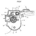
Fig. 4] Fig. 4 is a plan view of the wire feeding device; - [
Fig. 5] Fig. 5 is a perspective view of an essential portion of a reinforcing bar binding machine in a state where the window cover is opened; - [
Fig. 6] Fig. 6 is a back view of the essential portion of the reinforcing bar binding machine from the back side; and - [
Fig. 7] Fig. 7 is a front view of the essential portion of the reinforcing bar binding machine from the front side. -
- 5
- Wire
- 9, 10
- Feed gear
- 16
- Partition plate
- 18, 19
- Bulkhead (wall)
- 28, 29
- Discharge portion
- An exemplary embodiment of the invention is described in reference to drawings.
InFig. 1 to Fig. 3 , the reference numeral 1 denotes a reinforcing bar binding machine. In the reinforcing bar binding machine 1, in ahousing chamber 3 provided in abinding machine body 2, awire reel 4 around which a reinforcingbar binding wire 5 is wound is fitted, and a predetermined length of thewire 5 is fed to aguide part 6 provided on the tip end of thebinding machine body 2 while rotating thewire reel 4, and theguide part 6 curls thewire 5 and feeds out the wire to the circumference of the reinforcing bars a disposed on the inner side of theguide part 6 and winds the wire around the reinforcing bars a, and then the root side of thewire 5 is cut, and the wound portion is twisted to bind the reinforcing bars a. - Between the
housing chamber 3 and theguide part 6, aguide tube 7 through which thewire 5 is inserted is provided as shown inFig. 2 , and at the middle of theguide tube 7, a wire feeding device (described later) to be driven by anelectric motor 8 is disposed. At theguide part 6, a wire cutting device and a wire twisting device are disposed although these are not shown. When a switch is turned ON by a trigger, the wire feeding device is actuated, and thewire 5 wound around thewire reel 4 housed in thehousing chamber 3 is fed to theguide part 6 ahead of the bindingmachine body 2. - The
guide part 6 curls thewire 5 so that thewire 5 fed into the bindingmachine body 2 is delivered while being curled, and curls thewire 5 and then winds it around the reinforcing bars a between the guide part and alower guide 9. Then, after thewire 5 is wound around the reinforcing bars a, the wire is cut by a cutting device driven by another electric motor, and twisted by the twisting device to bind the reinforcing bars. - Actuations, etc. , of the wire feed gears, the wire cutting device, and the wire twisting device are sequence-controlled by a control circuit not shown. The control circuit also measures the feeding amount of the
wire 5. - The wire feeding device which pulls out the wire from the wire reel and feeds it to the
guide part 6 includes, as shown inFig. 2 , theguide tube 7 constituting a wire passage, a pair of feed gears 9 and 10 disposed oppositely at the middle portion of theguide tube 7, and anelectric motor 8 which drives the feed gears 9 and 10. - The
guide tube 7 includes aconical introduction tube 7a which introduces thewire 5 pulled out from the wire reel, and amain guide tube 7b which guides thewire 5 fed-out by the feed gears 9 and 10 to theguide part 6. - One
feed gear 9 is a drive gear and joined to theelectric motor 8, however, theother feed gear 10 is a free gear and provided on one end of anarm 13 which turns around ashaft 12. Thearm 13 is for spacing between the feed gears 9 and 10 and inserting thewire 5 therebetween, and applying a fixed pressing force to thewire 5 by pressing the other end of thearm 13 by a spring (not shown). On the outer peripheries of the feed gears 9 and 10, feedgrooves 14 are formed, and thewire 5 is sandwiched between thefeed grooves 14 of the twofeed gears feed grooves 14 and thewire 5 feed out thewire 5. - As shown in
Fig. 2 andFig. 3 , the feed gears 9 and 10 are partitioned from theelectric motor 8 and areduction gear 15 of theelectric motor 8 by thepartition plate 16. Above thepartition plate 16, theguide tube 7 and the pair of feed gears 9 and 10 for thewire 5 are disposed. Theseguide tube 7 and feed gears 9 and 10 are disposed at a deflected position on one side of thepartition plate 16, and theother side portion 17 is an empty space. - Next, most of the circumference of the
partition plate 16 is covered bybulkheads window cover 20, and between thepartition plate 16 andbulkheads window cover 20, a feed gear housing is formed. In other words, theside 21 on thefree gear 10 side of thepartition plate 16, theside 22 closer to thefree gear 10 side than theintroduction tube 7a, and thehalf 23 on themain guide tube 7b side of the side on themain guide tube 7b side, are in contact with thebulkhead 18 provided on the bindingmachine body 2. In theempty space 17, theside 24 opposite to thefree gear 10 is in contact with the inner wall of adoor cover 25 covering a housing of theelectric motor 8. The door cover 25 turns to open and close, and normally, it is fixed to the binding machine body by a screw 26 (seeFig. 5 ), and when maintenance is necessary, the door cover can be opened by removing thescrew 26. - The
partition plate 16 and thebulkheads like sealing member 27. At the portion at which thepartition plate 16 comes into contact with the bulkheads, the sealingmember 27 is disposed. The sealingmember 27 is sandwiched and fixed between thepartition plate 16 and asupport plate 30 disposed below the partition plate. Therefore, the sealingmember 27 is provided lower than the upper surface of thepartition plate 16. However, it is also possible that the sealingmember 27 is adhesively fixed to the peripheral surface of thepartition plate 16 so as to become flush with the upper surface of thepartition plate 16. - The sealing
member 27 is also attached to the circumference of themain guide tube 7b. - Between the
partition plate 16 and thebulkheads member 27 is interposed, so that dust does not enter the housing of theelectric motor 8 and the inside of the bindingmachine body 2. - In a front side and a rear side of the
partition plate 16,discharge portions 28, 29 (first andsecond discharge portions 28, 29). Portions of thepartition plate 16 adjacent to thedischarge portions bulkheads 18, 19 (wall). That is, in two positions between thebulkhead 18 and thebulkheads 19, thedischarge portions front discharge portion 28 and therear discharge portion 29 are disposed so that thepartition plate 16 is positions between thefront discharge portion 28 and therear discharge portion 29. A portion between thefront discharge portion 28 and therear discharge portion 29 is a part of theempty space 17. On an upper surface of thepartition plate 16, the portion adjacent to thefront discharge portion 28 is continued straight to the portion adjacent to therear discharge portion 29. In addition, thefront discharge portion 28 and therear discharge portion 29 are provided so as to be flush with the upper surface of the partition plate 16 (a surface in a side of the feed gears 9, 10) or in a lower position (in a side of the electric motor 8) than the upper surface of thepartition plate 16. - The upper portion of the
partition plate 16 is covered by awindow cover 20. Thewindow cover 20 is supported so as to turn up and down on the upper portion of the bindingmachine body 2, and accordingly, by opening the upper portion of the feed gear housing, awire 5 of a new wire reel is inserted into theguide tube 7 or maintenance and cleaning are performed. As well as the upper portions of the bulkheads, the opening of the discharge portions is also formed so as to open and close. When thewindow cover 20 is closed, the window cover is elastically engaged by astopper 31 on the tip end. - According to the configuration described above, as a result of repetition of feeding of the
wire 5, wire shavings are scattered and accumulated inside the feed gear housing. To remove the wire shavings, after thewindow cover 20 is opened, air is blown to the inside of the feed gear housing by an air blower. In this case, air is blown from therear discharge portion 29 to thefront discharge portion 28. Accordingly, air is smoothly blown, and wire shavings are blown off and discharged to the outside from thedischarge portion 28. Thedischarge portions partition plate 16, so that wire shavings are blown off at one time without being accumulated in the housing of the feed gears 9 and 10. On an upper surface of thepartition plate 16, the portion adjacent to thefront discharge portion 28 is continued straight to the portion adjacent to therear discharge portion 29, so that the air flow between therear discharge portion 29 and thefront discharge portion 28 is not interrupted. Further, by blowing air on thepartition plate 16 by an air blower, wire shavings accumulated by the side of the bulkheads are blown off from the discharge portions. At this time, between thepartition plate 16 and the bulkheads, the sealing member is disposed, so that even if wire shavings are strongly blown off, the wire shavings do not enter the housing of themotor 8 and the inside of the binding machine body. Of course, the wire shavings can be removed by a brush, etc. In every case, wire shavings can be easily and reliably removed. - While description has been made in connection with specific exemplary embodiment of the invention, it will be obvious to those skilled in the art that various changes and modification may be made therein without departing from the present invention.
It is aimed, therefore, to cover in the appended claims all such changes and modifications falling within the true spirit and scope of the present invention. - The present invention is applicable to a wire feeding mechanism of a reinforcing bar binding machine.
Claims (5)
- A reinforcing bar binding machine comprising:a pair of feed gears (9, 10) for feeding a wire (5) from a wire reel (4) mounted on a binding machine body (2);an electric motor (8) for driving the feed gears (9, 10);a partition plate (16) provided between the feed gears (9, 10) and the electric motor (8) to partition the feed gears (9, 10) and the electric motor (8); andfirst and second discharge portions (28, 29) for discharging wire shavings,wherein the partition plate (16) is surrounded by a wall (18, 19) except for portions of the partition plate (16) being adjacent to the first and second discharge portions, andwherein the first and second discharge portions (28, 29) are disposed so that the partition plate (16) positions between the first and second discharge portions (28, 29).
- The reinforcing bar binding machine according to Claim 1, wherein the discharge portions (28, 29) are flush with a surface of the partition plate (16) in a side of the feed gears (9, 10).
- The reinforcing bar binding machine according to Claim 1, wherein the discharge portions (28, 29) are disposed in a side of the electric motor (8) than a surface of the partition plate (16) in a side of the feed gears (9, 10).
- The reinforcing bar binding machine according to any one of Claims 1 to 3, wherein the partition plate (16) and the wall (18, 19) are brought into contact with each other via a sponge-like sealing member (27) interposing therebetween.
- The reinforcing bar binding machine according to any of Claims 1 to 4, wherein the discharge portions (28, 29) are capable of being opened and closed by a window cover (20) disposed on an upper portion of the partition plate (16).
Applications Claiming Priority (1)
| Application Number | Priority Date | Filing Date | Title |
|---|---|---|---|
| JP2008130639A JP5045547B2 (en) | 2008-05-19 | 2008-05-19 | Rebar binding machine |
Publications (2)
| Publication Number | Publication Date |
|---|---|
| EP2123403A1 true EP2123403A1 (en) | 2009-11-25 |
| EP2123403B1 EP2123403B1 (en) | 2011-12-14 |
Family
ID=40902589
Family Applications (1)
| Application Number | Title | Priority Date | Filing Date |
|---|---|---|---|
| EP09005841A Active EP2123403B1 (en) | 2008-05-19 | 2009-04-27 | Reinforcing bar binding machine |
Country Status (14)
| Country | Link |
|---|---|
| US (1) | US8397767B2 (en) |
| EP (1) | EP2123403B1 (en) |
| JP (1) | JP5045547B2 (en) |
| KR (1) | KR101563745B1 (en) |
| CN (1) | CN101585423B (en) |
| AR (1) | AR071820A1 (en) |
| AT (1) | ATE536962T1 (en) |
| BR (1) | BRPI0901549B1 (en) |
| CA (1) | CA2664888C (en) |
| CL (1) | CL2009001206A1 (en) |
| ES (1) | ES2378493T3 (en) |
| RU (1) | RU2490407C2 (en) |
| TW (1) | TWI485089B (en) |
| WO (1) | WO2009142210A1 (en) |
Cited By (1)
| Publication number | Priority date | Publication date | Assignee | Title |
|---|---|---|---|---|
| EP4296452A3 (en) * | 2022-05-30 | 2024-03-20 | Max Co., Ltd. | Binding machine and binding device |
Families Citing this family (25)
| Publication number | Priority date | Publication date | Assignee | Title |
|---|---|---|---|---|
| TWD136590S1 (en) * | 2009-04-14 | 2010-08-21 | 美克司股份有限公司 | Rebar tying machine |
| CN103982043B (en) * | 2013-12-17 | 2016-01-13 | 桐乡市景顺机电有限公司 | Electric steel binding machine |
| SMT202400349T1 (en) | 2015-07-22 | 2024-11-15 | Max Co Ltd | Reel for binding machine |
| EP4707184A2 (en) * | 2015-07-22 | 2026-03-11 | Max Co., Ltd. | Binding machine |
| KR102130394B1 (en) | 2015-07-22 | 2020-07-06 | 마크스 가부시기가이샤 | Binding machine |
| CN107472575B (en) * | 2015-08-11 | 2019-04-23 | 许修义 | A tailing discharge structure of an automatic cable tie tool |
| JP6674265B2 (en) * | 2016-01-28 | 2020-04-01 | 株式会社マキタ | Rebar binding machine |
| US10457429B1 (en) | 2016-09-03 | 2019-10-29 | Johnson International Corporation | Pair of jaws for a twist-tying machine |
| JP6790823B2 (en) | 2016-12-29 | 2020-11-25 | マックス株式会社 | Cable ties |
| JP6730940B2 (en) * | 2017-01-10 | 2020-07-29 | 株式会社マキタ | Binding machine |
| WO2018131218A1 (en) * | 2017-01-10 | 2018-07-19 | 株式会社マキタ | Binding machine |
| JP7017926B2 (en) * | 2017-12-25 | 2022-02-09 | 株式会社マキタ | Reinforcing bar binding machine |
| USD858239S1 (en) * | 2018-01-18 | 2019-09-03 | Max Co., Ltd. | Binding tool |
| JP7099089B2 (en) * | 2018-06-29 | 2022-07-12 | マックス株式会社 | Cable ties |
| JP7100568B2 (en) * | 2018-11-16 | 2022-07-13 | 株式会社マキタ | Reinforcing bar binding machine |
| JP1658513S (en) * | 2019-09-03 | 2020-04-27 | ||
| EP4051853B1 (en) * | 2019-10-28 | 2025-04-16 | Husqvarna Ab | Rebar tying device comprising a wire locking mechanism and a control unit for controlling the wire locking mechanism |
| SE543449C2 (en) * | 2019-10-28 | 2021-02-23 | Husqvarna Ab | Rebar tying device comprising a wire locking mechanism and a control unit for controlling the wire locking mechanism |
| TWI843938B (en) | 2020-02-10 | 2024-06-01 | 日商美克司股份有限公司 | Bundling Machine |
| JP7427994B2 (en) | 2020-02-10 | 2024-02-06 | マックス株式会社 | Binding machine |
| USD1042068S1 (en) * | 2021-05-19 | 2024-09-17 | Gustav Klauke Gmbh | Hydraulic press tool |
| CN114293782B (en) * | 2021-12-26 | 2023-05-02 | 中铁二十二局集团有限公司 | Wire binding winding equipment for building |
| CN115788077B (en) * | 2022-12-15 | 2023-09-15 | 广州珠江外资建筑设计院有限公司 | A construction method for prefabricated concrete bay windows with upper beam steel bars pre-tied |
| JP1768705S (en) * | 2023-06-13 | 2024-04-22 | Rebar Tying Machine | |
| JP1766305S (en) * | 2023-06-13 | 2024-03-25 | Rebar binding machine body |
Citations (3)
| Publication number | Priority date | Publication date | Assignee | Title |
|---|---|---|---|---|
| JP2001038647A (en) * | 1999-07-23 | 2001-02-13 | Max Co Ltd | Reinforcement binding machine |
| JP3574259B2 (en) | 1996-02-26 | 2004-10-06 | コニカミノルタホールディングス株式会社 | Rotation control device |
| WO2005037490A1 (en) * | 2003-10-17 | 2005-04-28 | Guifang Zhu | A wire bundling device for fixing and bundling reinforcing steels |
Family Cites Families (9)
| Publication number | Priority date | Publication date | Assignee | Title |
|---|---|---|---|---|
| US4534817A (en) * | 1983-04-08 | 1985-08-13 | Sullivan Denis P O | Automatic bundle-tying tool |
| JP2574259B2 (en) | 1986-09-17 | 1997-01-22 | 株式会社 アマダ | Stepping motor drive system |
| JPH053494A (en) | 1991-06-25 | 1993-01-08 | Nec Commun Syst Ltd | Private branch of exchange |
| JPH053494U (en) * | 1991-07-03 | 1993-01-19 | マツクス株式会社 | Wire guide device for binding machine |
| US5824984A (en) * | 1997-03-31 | 1998-10-20 | Morrow; John A. | Portable electric wire cutter |
| JP2002298995A (en) * | 2001-03-30 | 2002-10-11 | Jst Mfg Co Ltd | Coaxial cable bundling member using resin solder, coaxial cable electric connector, and method of connecting bundling member to coaxial cable or electric connector |
| CN1258410C (en) * | 2001-09-28 | 2006-06-07 | 美克司株式会社 | Rebar binding machine and reel for the machine |
| AU2002335474B2 (en) * | 2001-09-28 | 2007-08-30 | Max Kabushiki Kaisha | Reinforcement binding machine, reel, and method of detecting rotation of reel |
| TWM369304U (en) * | 2009-04-30 | 2009-11-21 | Xiao-Jie Yi | Electric portable strapping machine |
-
2008
- 2008-05-19 JP JP2008130639A patent/JP5045547B2/en active Active
-
2009
- 2009-04-24 TW TW098113586A patent/TWI485089B/en active
- 2009-04-27 EP EP09005841A patent/EP2123403B1/en active Active
- 2009-04-27 ES ES09005841T patent/ES2378493T3/en active Active
- 2009-04-27 AT AT09005841T patent/ATE536962T1/en active
- 2009-04-30 CA CA2664888A patent/CA2664888C/en active Active
- 2009-05-14 BR BRPI0901549-3A patent/BRPI0901549B1/en active IP Right Grant
- 2009-05-18 AR ARP090101774A patent/AR071820A1/en not_active Application Discontinuation
- 2009-05-18 RU RU2009118690/13A patent/RU2490407C2/en active
- 2009-05-18 CL CL2009001206A patent/CL2009001206A1/en unknown
- 2009-05-18 US US12/467,444 patent/US8397767B2/en active Active
- 2009-05-19 KR KR1020090043661A patent/KR101563745B1/en active Active
- 2009-05-19 WO PCT/JP2009/059214 patent/WO2009142210A1/en not_active Ceased
- 2009-05-19 CN CN2009102030848A patent/CN101585423B/en active Active
Patent Citations (4)
| Publication number | Priority date | Publication date | Assignee | Title |
|---|---|---|---|---|
| JP3574259B2 (en) | 1996-02-26 | 2004-10-06 | コニカミノルタホールディングス株式会社 | Rotation control device |
| JP2001038647A (en) * | 1999-07-23 | 2001-02-13 | Max Co Ltd | Reinforcement binding machine |
| JP3582411B2 (en) | 1999-07-23 | 2004-10-27 | マックス株式会社 | Rebar binding machine |
| WO2005037490A1 (en) * | 2003-10-17 | 2005-04-28 | Guifang Zhu | A wire bundling device for fixing and bundling reinforcing steels |
Cited By (1)
| Publication number | Priority date | Publication date | Assignee | Title |
|---|---|---|---|---|
| EP4296452A3 (en) * | 2022-05-30 | 2024-03-20 | Max Co., Ltd. | Binding machine and binding device |
Also Published As
| Publication number | Publication date |
|---|---|
| CN101585423B (en) | 2011-10-05 |
| RU2009118690A (en) | 2010-11-27 |
| ES2378493T3 (en) | 2012-04-13 |
| BRPI0901549A2 (en) | 2010-05-18 |
| CN101585423A (en) | 2009-11-25 |
| WO2009142210A1 (en) | 2009-11-26 |
| US20090283170A1 (en) | 2009-11-19 |
| JP5045547B2 (en) | 2012-10-10 |
| CL2009001206A1 (en) | 2010-09-21 |
| KR101563745B1 (en) | 2015-10-27 |
| BRPI0901549B1 (en) | 2019-06-04 |
| RU2490407C2 (en) | 2013-08-20 |
| AR071820A1 (en) | 2010-07-14 |
| CA2664888A1 (en) | 2009-11-19 |
| CA2664888C (en) | 2016-09-06 |
| EP2123403B1 (en) | 2011-12-14 |
| ATE536962T1 (en) | 2011-12-15 |
| TW201002575A (en) | 2010-01-16 |
| KR20090120426A (en) | 2009-11-24 |
| US8397767B2 (en) | 2013-03-19 |
| JP2009275485A (en) | 2009-11-26 |
| TWI485089B (en) | 2015-05-21 |
Similar Documents
| Publication | Publication Date | Title |
|---|---|---|
| EP2123403B1 (en) | Reinforcing bar binding machine | |
| EP2254452B1 (en) | Vacuum cleaner and dust separation apparatus thereof | |
| KR101731765B1 (en) | Reinforcing bar binding machine | |
| TWI530608B (en) | Reinforcing bar binding machine | |
| JP5294440B2 (en) | Air conditioner | |
| EP0839717A1 (en) | Automatic cable tie installation tool | |
| JP5272670B2 (en) | Bag medicine dispenser | |
| CN111874309B (en) | Electric adhesive tape harness wire device | |
| US12439895B2 (en) | Structure of a honeycomb frame | |
| CN212290458U (en) | Electric adhesive tape wire bundling device | |
| CN220795959U (en) | A sell subassembly for ration vending | |
| KR940002786B1 (en) | Toothpaste Automatic Extruder | |
| EP4296452A2 (en) | Binding machine and binding device | |
| CN215707390U (en) | Iron wire knob device is tied up to reinforcing bar | |
| JP2021021272A (en) | Reinforcement binding machine set | |
| CN215151983U (en) | Rivet feeding and riveting mechanism | |
| CN209453575U (en) | A kind of riveting robot control cabinet | |
| JP2022127498A (en) | Binding equipment and binding machine | |
| JP2005186260A (en) | Cutter for straight member | |
| JPH0351109Y2 (en) | ||
| JP2002127040A (en) | Cutter mechanism of remaining portion of connecting band in nailing machine | |
| JP2000251140A (en) | Merchandise pushing device | |
| JP2008309454A (en) | Component extraction device and air conditioner indoor unit equipped with component extraction device | |
| JPH0574642U (en) | Paper cutting machine | |
| DE10021416A1 (en) | Device to press plastics or paste matter from cartridge; has drive element surrounded by propulsion gears to push supply piston and driven by axial driving pinion of electric motor |
Legal Events
| Date | Code | Title | Description |
|---|---|---|---|
| PUAI | Public reference made under article 153(3) epc to a published international application that has entered the european phase |
Free format text: ORIGINAL CODE: 0009012 |
|
| AK | Designated contracting states |
Kind code of ref document: A1 Designated state(s): AT BE BG CH CY CZ DE DK EE ES FI FR GB GR HR HU IE IS IT LI LT LU LV MC MK MT NL NO PL PT RO SE SI SK TR |
|
| 17P | Request for examination filed |
Effective date: 20091216 |
|
| GRAP | Despatch of communication of intention to grant a patent |
Free format text: ORIGINAL CODE: EPIDOSNIGR1 |
|
| GRAS | Grant fee paid |
Free format text: ORIGINAL CODE: EPIDOSNIGR3 |
|
| GRAA | (expected) grant |
Free format text: ORIGINAL CODE: 0009210 |
|
| AK | Designated contracting states |
Kind code of ref document: B1 Designated state(s): AT BE BG CH CY CZ DE DK EE ES FI FR GB GR HR HU IE IS IT LI LT LU LV MC MK MT NL NO PL PT RO SE SI SK TR |
|
| REG | Reference to a national code |
Ref country code: GB Ref legal event code: FG4D |
|
| REG | Reference to a national code |
Ref country code: CH Ref legal event code: EP |
|
| REG | Reference to a national code |
Ref country code: IE Ref legal event code: FG4D |
|
| REG | Reference to a national code |
Ref country code: DE Ref legal event code: R096 Ref document number: 602009004113 Country of ref document: DE Effective date: 20120209 |
|
| REG | Reference to a national code |
Ref country code: NL Ref legal event code: VDEP Effective date: 20111214 |
|
| REG | Reference to a national code |
Ref country code: SE Ref legal event code: TRGR |
|
| REG | Reference to a national code |
Ref country code: ES Ref legal event code: FG2A Ref document number: 2378493 Country of ref document: ES Kind code of ref document: T3 Effective date: 20120413 |
|
| PG25 | Lapsed in a contracting state [announced via postgrant information from national office to epo] |
Ref country code: NO Free format text: LAPSE BECAUSE OF FAILURE TO SUBMIT A TRANSLATION OF THE DESCRIPTION OR TO PAY THE FEE WITHIN THE PRESCRIBED TIME-LIMIT Effective date: 20120314 Ref country code: LT Free format text: LAPSE BECAUSE OF FAILURE TO SUBMIT A TRANSLATION OF THE DESCRIPTION OR TO PAY THE FEE WITHIN THE PRESCRIBED TIME-LIMIT Effective date: 20111214 |
|
| LTIE | Lt: invalidation of european patent or patent extension |
Effective date: 20111214 |
|
| PG25 | Lapsed in a contracting state [announced via postgrant information from national office to epo] |
Ref country code: GR Free format text: LAPSE BECAUSE OF FAILURE TO SUBMIT A TRANSLATION OF THE DESCRIPTION OR TO PAY THE FEE WITHIN THE PRESCRIBED TIME-LIMIT Effective date: 20120315 Ref country code: NL Free format text: LAPSE BECAUSE OF FAILURE TO SUBMIT A TRANSLATION OF THE DESCRIPTION OR TO PAY THE FEE WITHIN THE PRESCRIBED TIME-LIMIT Effective date: 20111214 Ref country code: SI Free format text: LAPSE BECAUSE OF FAILURE TO SUBMIT A TRANSLATION OF THE DESCRIPTION OR TO PAY THE FEE WITHIN THE PRESCRIBED TIME-LIMIT Effective date: 20111214 Ref country code: HR Free format text: LAPSE BECAUSE OF FAILURE TO SUBMIT A TRANSLATION OF THE DESCRIPTION OR TO PAY THE FEE WITHIN THE PRESCRIBED TIME-LIMIT Effective date: 20111214 Ref country code: LV Free format text: LAPSE BECAUSE OF FAILURE TO SUBMIT A TRANSLATION OF THE DESCRIPTION OR TO PAY THE FEE WITHIN THE PRESCRIBED TIME-LIMIT Effective date: 20111214 |
|
| PG25 | Lapsed in a contracting state [announced via postgrant information from national office to epo] |
Ref country code: BE Free format text: LAPSE BECAUSE OF FAILURE TO SUBMIT A TRANSLATION OF THE DESCRIPTION OR TO PAY THE FEE WITHIN THE PRESCRIBED TIME-LIMIT Effective date: 20111214 Ref country code: CY Free format text: LAPSE BECAUSE OF FAILURE TO SUBMIT A TRANSLATION OF THE DESCRIPTION OR TO PAY THE FEE WITHIN THE PRESCRIBED TIME-LIMIT Effective date: 20111214 |
|
| PG25 | Lapsed in a contracting state [announced via postgrant information from national office to epo] |
Ref country code: SK Free format text: LAPSE BECAUSE OF FAILURE TO SUBMIT A TRANSLATION OF THE DESCRIPTION OR TO PAY THE FEE WITHIN THE PRESCRIBED TIME-LIMIT Effective date: 20111214 Ref country code: EE Free format text: LAPSE BECAUSE OF FAILURE TO SUBMIT A TRANSLATION OF THE DESCRIPTION OR TO PAY THE FEE WITHIN THE PRESCRIBED TIME-LIMIT Effective date: 20111214 Ref country code: BG Free format text: LAPSE BECAUSE OF FAILURE TO SUBMIT A TRANSLATION OF THE DESCRIPTION OR TO PAY THE FEE WITHIN THE PRESCRIBED TIME-LIMIT Effective date: 20120314 Ref country code: IS Free format text: LAPSE BECAUSE OF FAILURE TO SUBMIT A TRANSLATION OF THE DESCRIPTION OR TO PAY THE FEE WITHIN THE PRESCRIBED TIME-LIMIT Effective date: 20120414 Ref country code: CZ Free format text: LAPSE BECAUSE OF FAILURE TO SUBMIT A TRANSLATION OF THE DESCRIPTION OR TO PAY THE FEE WITHIN THE PRESCRIBED TIME-LIMIT Effective date: 20111214 |
|
| PG25 | Lapsed in a contracting state [announced via postgrant information from national office to epo] |
Ref country code: PL Free format text: LAPSE BECAUSE OF FAILURE TO SUBMIT A TRANSLATION OF THE DESCRIPTION OR TO PAY THE FEE WITHIN THE PRESCRIBED TIME-LIMIT Effective date: 20111214 Ref country code: PT Free format text: LAPSE BECAUSE OF FAILURE TO SUBMIT A TRANSLATION OF THE DESCRIPTION OR TO PAY THE FEE WITHIN THE PRESCRIBED TIME-LIMIT Effective date: 20120416 Ref country code: RO Free format text: LAPSE BECAUSE OF FAILURE TO SUBMIT A TRANSLATION OF THE DESCRIPTION OR TO PAY THE FEE WITHIN THE PRESCRIBED TIME-LIMIT Effective date: 20111214 |
|
| REG | Reference to a national code |
Ref country code: AT Ref legal event code: MK05 Ref document number: 536962 Country of ref document: AT Kind code of ref document: T Effective date: 20111214 |
|
| PLBE | No opposition filed within time limit |
Free format text: ORIGINAL CODE: 0009261 |
|
| STAA | Information on the status of an ep patent application or granted ep patent |
Free format text: STATUS: NO OPPOSITION FILED WITHIN TIME LIMIT |
|
| PG25 | Lapsed in a contracting state [announced via postgrant information from national office to epo] |
Ref country code: DK Free format text: LAPSE BECAUSE OF FAILURE TO SUBMIT A TRANSLATION OF THE DESCRIPTION OR TO PAY THE FEE WITHIN THE PRESCRIBED TIME-LIMIT Effective date: 20111214 |
|
| 26N | No opposition filed |
Effective date: 20120917 |
|
| PG25 | Lapsed in a contracting state [announced via postgrant information from national office to epo] |
Ref country code: IT Free format text: LAPSE BECAUSE OF FAILURE TO SUBMIT A TRANSLATION OF THE DESCRIPTION OR TO PAY THE FEE WITHIN THE PRESCRIBED TIME-LIMIT Effective date: 20111214 Ref country code: MC Free format text: LAPSE BECAUSE OF NON-PAYMENT OF DUE FEES Effective date: 20120430 |
|
| REG | Reference to a national code |
Ref country code: DE Ref legal event code: R097 Ref document number: 602009004113 Country of ref document: DE Effective date: 20120917 |
|
| PG25 | Lapsed in a contracting state [announced via postgrant information from national office to epo] |
Ref country code: AT Free format text: LAPSE BECAUSE OF FAILURE TO SUBMIT A TRANSLATION OF THE DESCRIPTION OR TO PAY THE FEE WITHIN THE PRESCRIBED TIME-LIMIT Effective date: 20111214 |
|
| PG25 | Lapsed in a contracting state [announced via postgrant information from national office to epo] |
Ref country code: MK Free format text: LAPSE BECAUSE OF FAILURE TO SUBMIT A TRANSLATION OF THE DESCRIPTION OR TO PAY THE FEE WITHIN THE PRESCRIBED TIME-LIMIT Effective date: 20111214 |
|
| PG25 | Lapsed in a contracting state [announced via postgrant information from national office to epo] |
Ref country code: IE Free format text: LAPSE BECAUSE OF NON-PAYMENT OF DUE FEES Effective date: 20120427 |
|
| PG25 | Lapsed in a contracting state [announced via postgrant information from national office to epo] |
Ref country code: FI Free format text: LAPSE BECAUSE OF FAILURE TO SUBMIT A TRANSLATION OF THE DESCRIPTION OR TO PAY THE FEE WITHIN THE PRESCRIBED TIME-LIMIT Effective date: 20111214 |
|
| PG25 | Lapsed in a contracting state [announced via postgrant information from national office to epo] |
Ref country code: MT Free format text: LAPSE BECAUSE OF FAILURE TO SUBMIT A TRANSLATION OF THE DESCRIPTION OR TO PAY THE FEE WITHIN THE PRESCRIBED TIME-LIMIT Effective date: 20111214 |
|
| REG | Reference to a national code |
Ref country code: CH Ref legal event code: PL |
|
| PG25 | Lapsed in a contracting state [announced via postgrant information from national office to epo] |
Ref country code: CH Free format text: LAPSE BECAUSE OF NON-PAYMENT OF DUE FEES Effective date: 20130430 Ref country code: LI Free format text: LAPSE BECAUSE OF NON-PAYMENT OF DUE FEES Effective date: 20130430 |
|
| PG25 | Lapsed in a contracting state [announced via postgrant information from national office to epo] |
Ref country code: TR Free format text: LAPSE BECAUSE OF FAILURE TO SUBMIT A TRANSLATION OF THE DESCRIPTION OR TO PAY THE FEE WITHIN THE PRESCRIBED TIME-LIMIT Effective date: 20111214 |
|
| PG25 | Lapsed in a contracting state [announced via postgrant information from national office to epo] |
Ref country code: LU Free format text: LAPSE BECAUSE OF NON-PAYMENT OF DUE FEES Effective date: 20120427 |
|
| PG25 | Lapsed in a contracting state [announced via postgrant information from national office to epo] |
Ref country code: HU Free format text: LAPSE BECAUSE OF FAILURE TO SUBMIT A TRANSLATION OF THE DESCRIPTION OR TO PAY THE FEE WITHIN THE PRESCRIBED TIME-LIMIT Effective date: 20090427 |
|
| REG | Reference to a national code |
Ref country code: FR Ref legal event code: PLFP Year of fee payment: 8 |
|
| REG | Reference to a national code |
Ref country code: FR Ref legal event code: PLFP Year of fee payment: 9 |
|
| REG | Reference to a national code |
Ref country code: FR Ref legal event code: PLFP Year of fee payment: 10 |
|
| PGFP | Annual fee paid to national office [announced via postgrant information from national office to epo] |
Ref country code: DE Payment date: 20250305 Year of fee payment: 17 |
|
| PGFP | Annual fee paid to national office [announced via postgrant information from national office to epo] |
Ref country code: ES Payment date: 20250506 Year of fee payment: 17 |
|
| PGFP | Annual fee paid to national office [announced via postgrant information from national office to epo] |
Ref country code: SE Payment date: 20260312 Year of fee payment: 18 |
|
| PGFP | Annual fee paid to national office [announced via postgrant information from national office to epo] |
Ref country code: GB Payment date: 20260313 Year of fee payment: 18 |
|
| PGFP | Annual fee paid to national office [announced via postgrant information from national office to epo] |
Ref country code: FR Payment date: 20260309 Year of fee payment: 18 |