EP2123209A1 - Electronic endoscope apparatus - Google Patents
Electronic endoscope apparatus Download PDFInfo
- Publication number
- EP2123209A1 EP2123209A1 EP09006685A EP09006685A EP2123209A1 EP 2123209 A1 EP2123209 A1 EP 2123209A1 EP 09006685 A EP09006685 A EP 09006685A EP 09006685 A EP09006685 A EP 09006685A EP 2123209 A1 EP2123209 A1 EP 2123209A1
- Authority
- EP
- European Patent Office
- Prior art keywords
- circuit board
- image pickup
- insertion portion
- endoscope apparatus
- electronic endoscope
- Prior art date
- Legal status (The legal status is an assumption and is not a legal conclusion. Google has not performed a legal analysis and makes no representation as to the accuracy of the status listed.)
- Granted
Links
Images




Classifications
-
- A—HUMAN NECESSITIES
- A61—MEDICAL OR VETERINARY SCIENCE; HYGIENE
- A61B—DIAGNOSIS; SURGERY; IDENTIFICATION
- A61B1/00—Instruments for performing medical examinations of the interior of cavities or tubes of the body by visual or photographical inspection, e.g. endoscopes; Illuminating arrangements therefor
- A61B1/04—Instruments for performing medical examinations of the interior of cavities or tubes of the body by visual or photographical inspection, e.g. endoscopes; Illuminating arrangements therefor combined with photographic or television appliances
- A61B1/05—Instruments for performing medical examinations of the interior of cavities or tubes of the body by visual or photographical inspection, e.g. endoscopes; Illuminating arrangements therefor combined with photographic or television appliances characterised by the image sensor, e.g. camera, being in the distal end portion
-
- A—HUMAN NECESSITIES
- A61—MEDICAL OR VETERINARY SCIENCE; HYGIENE
- A61B—DIAGNOSIS; SURGERY; IDENTIFICATION
- A61B1/00—Instruments for performing medical examinations of the interior of cavities or tubes of the body by visual or photographical inspection, e.g. endoscopes; Illuminating arrangements therefor
- A61B1/00112—Connection or coupling means
- A61B1/00114—Electrical cables in or with an endoscope
-
- A—HUMAN NECESSITIES
- A61—MEDICAL OR VETERINARY SCIENCE; HYGIENE
- A61B—DIAGNOSIS; SURGERY; IDENTIFICATION
- A61B1/00—Instruments for performing medical examinations of the interior of cavities or tubes of the body by visual or photographical inspection, e.g. endoscopes; Illuminating arrangements therefor
- A61B1/012—Instruments for performing medical examinations of the interior of cavities or tubes of the body by visual or photographical inspection, e.g. endoscopes; Illuminating arrangements therefor characterised by internal passages or accessories therefor
- A61B1/018—Instruments for performing medical examinations of the interior of cavities or tubes of the body by visual or photographical inspection, e.g. endoscopes; Illuminating arrangements therefor characterised by internal passages or accessories therefor for receiving instruments
-
- A—HUMAN NECESSITIES
- A61—MEDICAL OR VETERINARY SCIENCE; HYGIENE
- A61B—DIAGNOSIS; SURGERY; IDENTIFICATION
- A61B1/00—Instruments for performing medical examinations of the interior of cavities or tubes of the body by visual or photographical inspection, e.g. endoscopes; Illuminating arrangements therefor
- A61B1/04—Instruments for performing medical examinations of the interior of cavities or tubes of the body by visual or photographical inspection, e.g. endoscopes; Illuminating arrangements therefor combined with photographic or television appliances
- A61B1/042—Instruments for performing medical examinations of the interior of cavities or tubes of the body by visual or photographical inspection, e.g. endoscopes; Illuminating arrangements therefor combined with photographic or television appliances characterised by a proximal camera, e.g. a CCD camera
-
- A—HUMAN NECESSITIES
- A61—MEDICAL OR VETERINARY SCIENCE; HYGIENE
- A61B—DIAGNOSIS; SURGERY; IDENTIFICATION
- A61B1/00—Instruments for performing medical examinations of the interior of cavities or tubes of the body by visual or photographical inspection, e.g. endoscopes; Illuminating arrangements therefor
- A61B1/04—Instruments for performing medical examinations of the interior of cavities or tubes of the body by visual or photographical inspection, e.g. endoscopes; Illuminating arrangements therefor combined with photographic or television appliances
- A61B1/045—Control thereof
Definitions
- the present invention relates to an electronic endoscope apparatus having a solid-state image pickup device (charged coupled device (CCD)) at a distal end portion of the apparatus.
- CCD charge coupled device
- endoscopes have been widely used in medical and industrial fields.
- Mainstream endoscopes that have been used to date employ an image guide so that a user can look into an eyepiece to observe an inside of a patient's body cavity or an interior of a jet engine, for example.
- endoscopes of recent years are incorporated with an image pickup apparatus to take images of the inside of a patient's body cavity or the interior of a jet engine, for example, to display endoscopic images on a display of an external monitor or the like.
- a technique for using such an image pickup apparatus with an endoscope is disclosed, for example, in Japanese Patent Application Laid-Open Publication No. 2006-15078 .
- the reference suggests a medical apparatus in which a camera head incorporating a CCD is mounted on an eyepiece of a conventional endoscope, with operating switches being provided at the camera head to configure a grasping portion.
- the conventional medical apparatus mentioned above uses a technique for acquiring an endoscopic image with a camera head mounted on an eyepiece of an endoscope, which is a conventional rigid endoscope having an image guide.
- the endoscope disclosed in the reference is a rigid endoscope having no bending portion at a distal end part thereof.
- endoscopes have a soft insertion portion having a distal end part at which a CCD is arranged.
- endoscopes are provided with a bending portion at a distal end portion of an insertion portion and include an operation portion provided with a bending operation knob being arranged for subjecting the bending portion to bending operation.
- such an operation portion has an interior which is provided with a fixed board that has been obtained by injection molding of metal.
- the fixed board is disposed in the operation portion in order to rotatably hold a sprocket of the bending operation knob, and also to maintain predetermined rigidity of the operation portion and to retain electrical connection to the ground of the insertion portion and a universal code.
- a medical-use endoscope needs to perform low-invasive examination and treatment, and is desired to have a small-diameter insertion portion to mitigate the stress imposed on a patient.
- an electronic endoscope apparatus having an insertion portion whose distal end portion is provided with an image pickup apparatus suitable for high pixel density, is required to use a thicker communication cable.
- Use of a thicker communication cable will necessitate the increase of an outer diameter of the insertion portion by an amount corresponding to the increase in the thickness of the cable.
- use of a thicker communication cable may cause a problem of preventing reduction of the diameter of the insertion portion.
- the operation portion in the endoscope including a bending portion disclosed in Japanese Patent Application Laid-Open Publication No. 10-234654 may be integrally provided with the camera head disclosed in Japanese Patent Application Laid-Open Publication No. 2006-15078 .
- the incorporation of the sprocket interlocking with the bending operation knob for bending operation of the bending portion and the incorporation of the camera head will necessitate the operation portion to have a large size.
- a female medical doctor whose hands may be smaller than those of a male medical doctor may have a difficulty more than ever in grasping such a large-size operation portion, raising another problem of bad operability.
- the present invention has been made in light of the circumstances described above and has as its object to provide an electronic endoscope apparatus which is able to prevent increase of size even when an image pickup apparatus that can acquire high-quality images is arranged at a distal end portion of an insertion portion, and in particular, prevent increase of a diameter of the insertion portion.
- an electronic endoscope apparatus of the present invention comprises: an image pickup apparatus which is mounted on a distal end portion of an insertion portion; an operation portion which is consecutively provided at the insertion portion and incorporated with a frame member; and an electrical cable which is extended from the operation portion and connected to an external device, wherein: the frame member is provided with a circuit board portion which establishes electrical connection between shields of the insertion portion and the electrical cable, and on which various electronic parts are mounted to exchange signals with the image pickup apparatus.
- the present invention configured as described above can realize an electronic endoscope apparatus which is able to prevent increase of size even when an image pickup apparatus that can acquire high-quality images is arranged at a distal end portion of an insertion portion, and in particular, prevent increase of a diameter of the insertion portion.
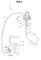
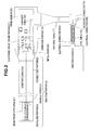
- Figs. 1 to 5 relate to the first embodiment of the present invention, in which: Fig. 1 is a view illustrating a configuration of an electronic endoscope system; Fig. 2 is a block diagram illustrating an electrical connection configuration of the electronic endoscope system; Fig. 3 is a view illustrating a configuration of an electronic circuit board; Fig. 4 is a cross-sectional view illustrating the electronic circuit board taken along IV-IV line of Fig. 3 ; Fig. 5 is a view illustrating an electrical connection of an insertion portion and an overall shield of a universal cable, with the electronic circuit board; Fig.
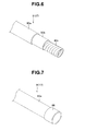
- FIG. 6 is an explanatory perspective view illustrating an internal configuration of the insertion portion and the universal cable
- Fig. 7 is a perspective view illustrating an end portion of the insertion portion and the universal cable
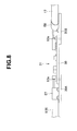
- Fig. 8 is a plan view illustrating a peripheral configuration of a circuit board portion according to a first modification
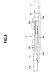
- Fig. 9 is a plan view illustrating a peripheral configuration of a circuit board portion according to a second modification.
- an electronic endoscope system 1 mainly includes an electronic endoscope apparatus 2, a light source device 3, a video processor 4 and a monitor 5.
- the electronic endoscope apparatus 2 includes an elongated insertion portion 9, an operation portion 10 and a universal cable 17 which is an electrical cable.
- the insertion portion 9 of the electronic endoscope apparatus 2 is sequentially configured, from a distal end, by a distal end portion 6, a bending portion 7 and a flexible tube portion 8.
- the operation portion 10 is connected to one end of the flexible tube portion 8 of the insertion portion 9, and includes a rear port 11, i.e. a bend preventing portion, a treatment instrument channel insertion portion 12, i.e. an opening portion of a treatment instrument channel, for inserting various treatment instruments arranged to the insertion portion 9, and an operation portion body 13.
- a rear port 11 i.e. a bend preventing portion
- a treatment instrument channel insertion portion 12 i.e. an opening portion of a treatment instrument channel, for inserting various treatment instruments arranged to the insertion portion 9, and an operation portion body 13.
- the operation portion body 13 is rotatably arranged with a bending operation knob 16 for bending operation of the bending portion 7 of the insertion portion 9, and also arranged with switches and the like associated with various endoscopic functions.
- the bending operation knob 16 is arranged in such a way that a UD bending operation knob 14 for performing vertical bending operation of the bending portion 7, and an RL bending operation knob 15 for performing horizontal bending operation of the bending portion 7, are overlapped one on the other.
- the universal cable 17 extended from the operation portion 10 has an extended end which is provided with an endoscope connector 18 which is detachable with the light source device 3.
- the electronic endoscope apparatus of the present embodiment is adapted to transmit illumination light from the light source device 3 to the distal end portion 6 by a light guide bundle.
- a coil cable 19 having a shape of a coil is extended from the endoscope connector 18.
- the coil cable 19 has an extended end which is provided with an electrical connector 20A which is detachable with the video processor 4.
- the video processor 4 is electrically connected to the monitor 5 for displaying endoscopic images, and processes image pickup signals that have been subjected to photoelectric conversion by an image pickup apparatus, which will be described later, of the electronic endoscope apparatus 2. The processed signals are then outputted to the monitor 5 as image signals.
- the insertion portion 9 of the electronic endoscope apparatus 2 has an entire length of about 2.5 m.
- the universal cable 17 connected to the electronic endoscope apparatus 2 through the operation portion 10 also has a length of about 2.5 m, with an entire length being 5.0 m or more.
- the electronic endoscope apparatus 2 is connected to the video processor 4 through the electrical connector 20A of the coil cable 19 having a length of about 2.0 m.
- the electronic endoscope apparatus 2 of the present embodiment has the insertion portion 9 whose distal end portion 6 is incorporated with an image pickup apparatus 21 provided with a solid-state image pickup device 22, such as a CCD and CMOS.
- a first composite cable 23 is extended from the solid-state image pickup device 22 and inserted into the operation portion 10 for arrangement therein, through the insertion portion 9.
- the first composite cable 23 is made up of a bundle of plural coaxial cables and is electrically connected to a circuit board portion 31 of a frame member 30 which is arranged in the operation portion 10.
- a second composite cable 32 which is inserted into the universal cable 17, is electrically connected to the circuit board portion 31.
- the second composite cable 32 is electrically connected to the video processor 4 through the endoscope connector 18 and through the coil cable having detachable electrical connectors 20A and 20B at both ends thereof.
- the frame member 30 arranged in the operation portion 10 is provided with a metal cover 35 which covers the circuit board portion 31 to ensure noninterference property and tolerance against electromagnetic influences on electronic parts mounted on the circuit board portion 31.
- the electronic parts mainly includes: an FPGA (field programmable gage array) 41, a solid-state image pickup device driver 42 and a solid-state image pickup device stabilized power source 43, which serve as input-side electronic parts for inputting signals into the solid-state image pickup device 22 through the first composite cable 23; and a plurality of, two here, transistors 44, a plurality of, two here, filters 45 and an amplifier 46, which serve as output-side electronic parts for outputting signals from the solid-state image pickup device 22 through the first composite cable 23.
- Other electronic parts include a resistor 47, a capacitor 48 and an LVDS (low voltage differential signaling) driver 49 which purposes, for example, stable transmission of transfer signals and noise reduction.
- An LVDS receiver is arranged in the video processor 4.
- the circuit board portion 31 is arranged with connectors 24 and 33 which electrically connect the first and second composite cables 23 and 32, respectively, to the electronic parts, and also electrically connect grounds of coaxial lines of the composite cables 23 and 32 as well as an overall shield, to grounds, which will be described later, formed on the frame member 30.
- an entirety of the frame member 30, including the circuit board portion 31, is configured by a rigid board which is made up of four ground layers 62 and 63, and a signal layer 64, with each of the layers and surfaces being ensured to be insulated by insulation layers 61.
- the frame member 30 of the present embodiment is a rigid board formed of a glass-epoxy board or a stacked ceramic board.
- ground layers 62 and 63 Of the four ground layers 62 and 63, two layers that sandwich the signal layer 64 are stacked as first ground layers 62 for shielding the coaxial lines of the composite cables 23 and 32, and two layers that are located on front and back surface sides are stacked as second ground layers 63 shielding overall the composite cables 23 and 32, the insertion portion 9 and the universal cable 17.
- the surface insulation layers 61 of the frame member 30 are edged and masked, for example, at four portions in front and back end surfaces to expose the second ground layers 63.
- the exposed second ground layers 63 can serve as fixing portions 52 and 54 to which the overall shields of the insertion portion 9 and the universal cable 17, respectively, are electrically connected.
- two fixing portions 52 are formed in the end surfaces, on the side to which the first composite cable 23 is connected.
- the two fixing portions 52 are each electrically connected to the overall shield of the insertion portion 9 (flexible tube portion 8) and are formed with holes 53 for fixedly screwing the rear port 11 of the operation portion 10 and the insertion portion 9.
- two fixing portions 54 are formed in the end surfaces, on the side to which the second composite cable 32 is connected.
- the two fixing portions 54 are each electrically connected to the overall shield of the universal cable 17 and are formed with holes 55 for fixedly screwing the operation portion body 13 of the operation portion 10 and the universal cable 17.
- the electrical connection of the insertion portion 9 and the universal cable 17 is established through bases 57 and 58, respectively, by which the overall shields are fixed to the respective end portions.
- the bases 57 and 58 are fixedly screwed to the corresponding fixing portions 52 and 54.
- each of the insertion portion 9 and the universal cable 17 is configured by inserting a braid 80b, i.e. a metal overall shield, and a metal flexible body 80c into a sheath 80a that is an outer enclosure.
- the braid 80b and the metal flexible body 80c are provided for adjusting the rigidity of the insertion portion 9 and the universal cable 17, but may be utilized as electrical shields.
- each of the insertion portion 9 and the universal cable 17 has an end portion which is provided with a metal annular body 88 that can be electrically connected to the braid 80b by soldering or crimping.
- the metal annular body 88 is electrically connected to the circuit board portion 31.
- the metal annular body 88 is electrically connected to each of the bases 57 and 58 provided at respective ends of the insertion portion 9 and the universal cable 17, which ends reside on the side of the frame member 30.
- the braid 80b serving as an overall shield of each of the insertion portion 9 and the universal cable 17 is electrically connected to each of the bases 57 and 58 fixed to the respective end portions.
- the electronic endoscope system 1 of the present embodiment configured as described above has the circuit board portion 31 arranged at the frame member 30 in the operation portion 10 of the electronic endoscope apparatus 2.
- the circuit board portion 31 is mounted with input/output electrical parts for exchanging electrical signals with the solid-state image pickup device 22 of the image pickup apparatus 21 which is loaded in the distal end portion 6 of the insertion portion 9.
- the composite cables 23 and 32 can be made thinner than conventional ones.
- use of the solid-state image pickup device 22 that can acquire high-quality endoscopic images of larger number of pixels than in the conventional devices may not necessitate the use of large-diameter composite cables 23 and 32.
- a transmission path may be made shorter than in the conventional apparatus.
- the entire transmission path from the video processor 4 to the solid-state image pickup device 22 of the image pickup apparatus 21 will be about 7.0 m.
- an input/output transmission path to/from the solid-state image pickup device 22 will be about 2.5 m, and an input/output transmission path to/from the video processor 4 will be about 4.5 m.
- the transfer path can be made shorter than in the conventional cases.
- the conventional electronic endoscope apparatus 2 had to use a driver in the video processor 4, for transmission of drive signals for driving the solid-state image pickup device 22 through a transmission path of 6.5 m, for example.
- Such transmission has caused drastic deterioration, such as attenuation or dullness, in the drive signals.
- the electronic endoscope apparatus 2 of the present embodiment has the operation portion 10 which is provided therein with a driver for relaying drive signals for driving the solid-state image pickup device 22. Therefore, the transmission path of the drive signals for the solid-state image pickup device 22 can be shortened to 2.5 m, here, which corresponds to a path from the operation portion 10 to the solid-state image pickup device 22.
- arranging the circuit board mounted with the driver in the operation portion 10 may contribute to mitigation of drive load, the mitigation being equal to the reduction in the length of the transmission path to 4.5 m, here, which corresponds to a path from the video processor 4 to the operation portion 10.
- circuits in the video processor 4 can be downsized. Further, since amplitude of the drive signals can be made small, radiation noise can be reduced.
- the conventional electronic endoscope apparatus 2 had to permit the video processor 4 to sample waveforms that have been dulled passing through the output-signal transmission path, which is 6.5 m long, for example, from the solid-state image pickup device 22 in the distal end portion 6.
- Such transmission can provide less sampling margin and thus it has been likely that the image qualities are deteriorated.
- the electronic endoscope apparatus 2 of the present embodiment can mount a sampling circuit as a relay in the operation portion 10. Accordingly, the distance up to the operation portion 10, which has been 6.5 m here, can be shortened to 2.5 m here. Thus, signal transmission to the video processor 4 can be stabilized to thereby obtain good images with less signal deterioration.
- arrangement of an A/D circuit in the operation portion 10 may also enable transmission with digital signals causing less deterioration, in the downstream of the operation portion 10.
- the composite cables 23 and 32 used for the electronic endoscope apparatus 2 of the present invention may be made thinner. Thinner composite cables can prevent increase of a diameter of the insertion portion 9 in the electronic endoscope apparatus 2 which is able to acquire higher-quality endoscopic images than in the conventional apparatus. In addition, as to the electronic endoscope apparatus 2 which acquires conventional-quality endoscopic images, thinner composite cables can also make a diameter of the insertion portion 9 small.
- the electronic endoscope apparatus 2 a conventionally used metal frame member incorporated in the operation portion 10 has been replaced by the frame member 30 of the present embodiment, which is in the form of a rigid stacked board.
- the replacement of the members has not increased the size of the operation portion 10, but the size and shape of the operation portion 10 have remained substantially the same as those of the conventionally used operation portion.
- the electronic endoscope apparatus 2 can provide a configuration which is so convenient for female medical doctors, in particular, as to prevent deterioration in grasping properties and operability.
- the video processor 4 can be configured by small-size electronic parts, whereby power consumption can be reduced and the size of the apparatus, per se, can be reduced.
- the insertion portion 9 and the universal cable 17 may not be directly fixed to the frame member 30 of the circuit board portion 31.
- metal frames 30A and 30B may be provided at both ends separately from the frame member 30, for connection with the insertion portion 9 and the universal cable 17, respectively.
- the metal frames 30A and 30B are located so that edge portions thereof may overlap with respective ends of the frame member 30 so as to be fixed by fixing screws 53a.
- the edge portions of the metal frames 30A and 30B are located so as to be overlapped with each other.
- the circuit board portion 31 formed of a stacked board and has a shape that matches the shape of a step formed by the metal frames 30A and 30b may be mounted on the metal frames 30A and 30B and fixed with fixing screws 53a.
- overlapping of the edge portions of the metal frames 30A and 30B can improve the strength and rigidity.
- use of a stacked board as the circuit board portion 31 can increase an area for mounting electronic parts.
- the electronic endoscope apparatus 2 may have a configuration in which the metal frames 30A and 30B are provided separately from the frame member 30 of the circuit board portion 31, for connection and fixation with the insertion portion 9 and the universal cable 17.
- the metal frames 30A and 30B are provided separately from the frame member 30 of the circuit board portion 31, for connection and fixation with the insertion portion 9 and the universal cable 17.
- Figs. 10 and 11 relate to the second embodiment of the present invention.
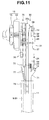
- Fig. 10 is an explanatory view illustrating a positional relationship chiefly between an electronic circuit board and a treatment instrument insertion channel in an operation portion.
- Fig. 11 is an explanatory view illustrating a positional relationship chiefly between the electronic circuit board and the treatment instrument insertion channel in the operation portion as viewed from an arrow VII of Fig. 10 .
- components having the same configurations as those in the first embodiment described above are designated with the same reference symbols to omit detailed description and operational advantages of the components.
- the electronic endoscope apparatus 2 of the present embodiment has the operation portion 10 which is incorporated with the frame member 30 having a frame board 30a made of metal, such as aluminum diecast, and having the circuit board portion 31 which is provided in parallel with the frame board 30a, at a position apart from one surface of the frame board 30a by a predetermined distance "d" (see Fig. 11 ).
- the circuit board portion 31 has a rigid board 37 on which the electronic parts explained in the first embodiment are mounted.
- the rigid board 37 is fixed at four corners using four leg members 38, i.e. stand spacers, so as to be parallel to the frame board 30a, being apart from the one surface of the frame board 30a by the predetermined distance "d".
- the distance "d" corresponds to a length of a step which is larger than a radius of a channel tube, so that runaway of the channel tube can be prevented.
- the four leg members 38 are adapted to fix the rigid board 37 and the frame board 30a by means of screws, for example, to establish electrical connection therebetween.
- the electronic endoscope apparatus 2 of the present embodiment has the operation portion 10 in which the frame member 30 is arranged, rotatably supporting the bending operation knob 16 and sprockets 75.
- the rigid board 37 of the circuit board portion 31 is provided in a space on a side opposed to the frame board 30a. Further, although not shown, top of the rigid board 37 of the circuit board portion 31 is provided with a metal cover to ensure noninterference property and tolerance against electromagnetic influences on electronic parts, as in the first embodiment.
- the electronic endoscope apparatus 2 includes: a metal treatment instrument channel 71 which is arranged being inserted into the insertion portion 9; and a channel tube 73 which is connected to the channel 71 in a water-tightly communicable manner through a connecting member 72 arranged at one diverged end of the treatment instrument channel 71.
- the channel tube 73 is a tubular body which is obtained by guarding a soft tube with a metal coil, the soft tube being formed of PTFE.
- the channel tube 73 is arranged being inserted into the universal cable 17, with a rear end portion thereof being detachably connected to a suction apparatus, not shown.
- the other diverged end of the treatment instrument channel 71 has an opening portion which provides a treatment instrument channel insertion portion 12 of the operation portion 10.
- the treatment instrument channel 71 and the channel tube 73 are arranged between the frame board 30a of the frame member 30 and the rigid board 37 of the circuit board portion 31.
- the treatment instrument channel insertion portion 12 of the treatment instrument channel 71 is arranged in a direction being away from the rigid board 37.
- the opening of the insertion portion 12 is positioned so as to have a predetermined distance "L" from a first connector 24 which is provided at the rigid board 37 to establish electrical connection with the first composite cable 23.
- the distance "L” is set so that the opening will not be positioned overlapping the board, at least in the longitudinal direction of the operation portion 10.
- the channel tube 73 is routed for arrangement, extending from a base 58 that fixes the universal cable 17 to the frame board 30a, running along one side portion of the rigid board 37, which side is far from the base 58, and passing an area between the frame board 30a and the rigid board 37 with the distance "L" therebetween.
- the channel tube 73 can be efficiently and stably arranged without wobbling in the operation portion 10.
- the channel tube 73 can be arranged at the same level as that of a position for establishing connection with the treatment instrument channel 71. Accordingly, the channel tube 73 can be prevented from being bent or being forcibly deformed.
- the bending operation knob 16 (15, 14) mentioned above is arranged on the other side of the frame board 30a.
- the bending operation knob 16 rotatably supports the two sprockets 75 and operates the sprockets 75 so that the sprockets can be individually rotated.
- the sprockets 75 each engage with chains 76 whose end portions are connected with respective bending operation wires 77.
- the bending operation wires 77 are inserted into respective coil tubes 78 which are arranged being inserted into the insertion portion 9, for extension up to the bending portion 7.
- the two bending operation knobs 14 and 15 are configured to individually rotate/operate the respective sprockets 75.
- rotation of the sprocket 75 concerned may permit the chain 76 interlocked with the sprocket 75 to move.
- the bending operation wire 77 concerned is pulled or slackened. In this way, the bending portion 7 of the insertion portion 9 is subjected to bending operation.
- the electronic endoscope apparatus 2 of the present embodiment configured as described above is provided with the rigid board 37 of the circuit board portion 31 in a space in the operation portion 10.
- Such a configuration can exert the advantages of the first embodiment, and at the same time can also prevent increase of size of the operation portion 10.
- the electronic endoscope apparatus 2 may be used together with a treatment instrument, such as an electric cautery, using high frequency, which instrument is inserted into the treatment instrument channel 71 from the treatment instrument channel insertion portion 12.
- a treatment instrument such as an electric cautery
- the treatment instrument channel insertion portion 12 of the treatment instrument channel 71 is provided in a direction being away from the circuit board portion 31 whose shield for preventing external electrical influences has been weakened.
- the treatment instrument channel insertion portion 12 is arranged so as to have the predetermined distance "L" from the first connector 24 for establishing electrical connection with the first composite cable 23. In this way, measures against noise are taken for the first composite cable 23, and at the same time, noninterference property and tolerance against electromagnetic influences on the circuit board portion 31 are improved.
- the electronic endoscope apparatus 2 of the present embodiment has a configuration with improved noninterference property and tolerance against electromagnetic influences which will be caused in the treatment using high frequency, such as by an electric cautery.
- Figs. 12 to 15 relate to the third embodiment of the present invention.
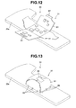
- Fig. 12 is a view illustrating a circuit board portion formed of a flexible printed board on which various electronic parts are mounted, the printed board being expanded on a frame member.
- Fig. 13 is a view illustrating the circuit board portion of Fig. 12 , in which the flexible printed board disposed on the frame member has been changed in shape to wrap the various electronic parts mounted on the flexible printed board.
- Fig. 14 is a cross-sectional view illustrating the circuit board portion disposed on the frame member, being in the state of Fig. 13 .
- Fig. 15 is a cross-sectional view illustrating a configuration of the flexible printed board. It should be noted that, in the following description as well, components having the same configurations as those in the first and second embodiments described above are designated with the same reference symbols to omit detailed description and operational advantages of the components.
- the circuit board portion 31 of the frame member 30 includes a flexible printed board (hereinafter abbreviated as "FPC") 81 on which the electronic parts explained in the first embodiment are mounted.
- the FPC 81 is arranged on one surface of the metal frame board 30a, with faces thereof, five here, being expanded. Of the five faces, the electronic parts are mounted on three faces, i.e. one face on the frame board 30a and two faces opposed to each other.
- One of the two opposed faces on which the electronic parts are mounted has an edge portion which is formed into a projected portion 82, and the other face has an edge portion which is formed into an engagement hole 83 for engagement with the projected portion 82.
- the projected portion 82 of the FPC 81 is brought into engagement first with the engagement hole 83 so that the two opposed faces can wrap the electronic parts.
- edge portions of two faces mounted with no electronic parts are changed in shapes to overlap with each other.
- the two overlapped edge portions are stuck by a tape 85 so as to press with each other.
- the circuit board portion 31 will have a shape of a deformed envelope, with the FPC 81 wrapping the electronic parts.
- the FPC 81 has a lower surface provided with a connecting pattern.
- the connecting pattern establishes electrical connection between the frame board 30a and ground layers that will be described later, through welded portions 86 which are obtained by soldering or the like, and is fixed to one surface of the frame board 30a.
- the FPC 81 is provided with through holes to electrically connect the frame board 30a with the ground layers.
- the FPC 81 is configured by four ground layers 92 and 93, and a signal layer 94, with each of the layers and surfaces being ensured to be insulated by insulation layers 91, similar to the first embodiment.
- the four ground layers 92 and 93 two layers that sandwich the signal layer 94 are stacked as first ground layers 92 to which shields of the coaxial lines of the composite cables 23 and 32 are connected for electrical connection, and two layers that are located on front and back surfaces are stacked as second ground layers 93 to which respective overall shields of the composite cables 23 and 32, the insertion portion 9 and the universal cable 17 are connected for electrical connection.
- the frame board 30a is provided with connectors which establish electrical connection for the composite cables 23 and 32.
- the composite cables 23 and 32 are configured to be electrically connected to the electronic parts on the circuit board portion 31 through conductive foils printed on the frame board 30a.
- the coaxial line shields and the overall shields are also electrically connected to the ground layers 92 and 93 of the FPC 81 through the conductive foils printed on the frame board 30a.
- the circuit board portion 31 of the present embodiment configured as described above wraps the electronic parts with the FPC 81 provided on the frame board 30a.
- the FPC 81 may have a configuration for ensuring noninterference property and tolerance against electromagnetic influences on the electronic parts.
- the second ground layers 93 structuring shield layers are located on the side of the surfaces of the enveloped shape.
- the FPC 81 configures a cover body for ensuring noninterference property and tolerance against electromagnetic influences from outside on the enclosed electronic parts.
- the electronic endoscope apparatus 2 of the present embodiment uses the FPC 81 for the circuit board portion 31 arranged in the operation portion 10.
- the FPC 81 for the circuit board portion 31 arranged in the operation portion 10.
- the metal cover has a shape that can form a space for distancing the cover from the electronic parts by a predetermined distance. For this reason, a space for providing the metal cover has to be ensured in the operation portion 10 according to thickness (size) of the metal cover. Thus, there has been a limitation in downsizing the operation portion 10 of the electronic endoscope apparatus 2.
- the FPC 81 which can freely change shape and can also serve as a metal cover, is arranged in the operation portion 10. Therefore, the space occupied by the circuit board portion 31 in the operation portion 10 can be made small. As a result, the operation portion 10 can be downsized compared with the case where a metal cover for covering electronic parts is provided. Further, owing to the absence of the metal cover from the circuit board portion 31, there is no necessity of providing the frame board 30a with a structure for fixing the metal cover. Thus, the number of parts can be reduced to thereby improve assembling properties.
- the present invention configured as described above, increase of size can be prevented in spite of the arrangement of an image pickup apparatus, which can acquire high-quality images, at the distal end portion of the insertion portion.
- the present invention can realize an electronic endoscope apparatus that can prevent increase of a diameter of the insertion portion.
- the configuration removed with the components may be extracted as an invention, provided the advantages as described can be obtained for the problems to be solved by the invention.
Landscapes
- Health & Medical Sciences (AREA)
- Life Sciences & Earth Sciences (AREA)
- Surgery (AREA)
- Biomedical Technology (AREA)
- Medical Informatics (AREA)
- Optics & Photonics (AREA)
- Pathology (AREA)
- Radiology & Medical Imaging (AREA)
- Biophysics (AREA)
- Engineering & Computer Science (AREA)
- Physics & Mathematics (AREA)
- Heart & Thoracic Surgery (AREA)
- Nuclear Medicine, Radiotherapy & Molecular Imaging (AREA)
- Molecular Biology (AREA)
- Animal Behavior & Ethology (AREA)
- General Health & Medical Sciences (AREA)
- Public Health (AREA)
- Veterinary Medicine (AREA)
- Endoscopes (AREA)
- Instruments For Viewing The Inside Of Hollow Bodies (AREA)
Abstract
Description
- The present invention relates to an electronic endoscope apparatus having a solid-state image pickup device (charged coupled device (CCD)) at a distal end portion of the apparatus.
- In recent years, endoscopes have been widely used in medical and industrial fields. Mainstream endoscopes that have been used to date employ an image guide so that a user can look into an eyepiece to observe an inside of a patient's body cavity or an interior of a jet engine, for example. Also, endoscopes of recent years are incorporated with an image pickup apparatus to take images of the inside of a patient's body cavity or the interior of a jet engine, for example, to display endoscopic images on a display of an external monitor or the like.
- A technique for using such an image pickup apparatus with an endoscope is disclosed, for example, in Japanese Patent Application Laid-Open Publication No.
2006-15078 - The conventional medical apparatus mentioned above uses a technique for acquiring an endoscopic image with a camera head mounted on an eyepiece of an endoscope, which is a conventional rigid endoscope having an image guide. The endoscope disclosed in the reference is a rigid endoscope having no bending portion at a distal end part thereof.
- As is well known, some electronic endoscope apparatus have a soft insertion portion having a distal end part at which a CCD is arranged. Generally, endoscopes are provided with a bending portion at a distal end portion of an insertion portion and include an operation portion provided with a bending operation knob being arranged for subjecting the bending portion to bending operation.
- As disclosed in Japanese Patent Application Laid-Open Publication No.
10-234654 - Meanwhile, in recent years, higher quality has been sought in endoscopic images acquired by an image pickup apparatus of an electronic endoscope apparatus. Accordingly, acquirement of high-resolution image necessitates increase of drive frequencies in an image pickup apparatus having increased number of pixels. In addition, if a distance is large from a video processor to an image pickup apparatus, as in the case of an endoscope, electrical resistance is reduced, necessitating use of a thick communication cable. In this case, output from the video processor has to be increased, which, coupled with the incorporated electronic parts therefor, will lead to the enlargement of a size of the video processor.
- On the other hand, a medical-use endoscope needs to perform low-invasive examination and treatment, and is desired to have a small-diameter insertion portion to mitigate the stress imposed on a patient. In particular, an electronic endoscope apparatus having an insertion portion whose distal end portion is provided with an image pickup apparatus suitable for high pixel density, is required to use a thicker communication cable. Use of a thicker communication cable will necessitate the increase of an outer diameter of the insertion portion by an amount corresponding to the increase in the thickness of the cable. Thus, use of a thicker communication cable may cause a problem of preventing reduction of the diameter of the insertion portion.
- For example, in order to shorten a distance from a video processor to an image pickup apparatus, the operation portion in the endoscope including a bending portion disclosed in Japanese Patent Application Laid-Open Publication No.
10-234654 2006-15078 - In particular, a female medical doctor whose hands may be smaller than those of a male medical doctor may have a difficulty more than ever in grasping such a large-size operation portion, raising another problem of bad operability.
- The present invention has been made in light of the circumstances described above and has as its object to provide an electronic endoscope apparatus which is able to prevent increase of size even when an image pickup apparatus that can acquire high-quality images is arranged at a distal end portion of an insertion portion, and in particular, prevent increase of a diameter of the insertion portion.
- In order to achieve above-described object, an electronic endoscope apparatus of the present invention comprises: an image pickup apparatus which is mounted on a distal end portion of an insertion portion; an operation portion which is consecutively provided at the insertion portion and incorporated with a frame member; and an electrical cable which is extended from the operation portion and connected to an external device, wherein: the frame member is provided with a circuit board portion which establishes electrical connection between shields of the insertion portion and the electrical cable, and on which various electronic parts are mounted to exchange signals with the image pickup apparatus.
- The present invention configured as described above can realize an electronic endoscope apparatus which is able to prevent increase of size even when an image pickup apparatus that can acquire high-quality images is arranged at a distal end portion of an insertion portion, and in particular, prevent increase of a diameter of the insertion portion.
- The above and other objects, features and advantages of the invention will become more clearly understood from the following description referring to the accompanying drawings.
-
-
Fig. 1 is a view illustrating a configuration of an electronic endoscope system, according to a first embodiment; -
Fig. 2 is a block diagram illustrating an electrical connection configuration of the electronic endoscope system, according to the first embodiment; -
Fig. 3 is a view illustrating a configuration of an electronic circuit board, according to the first embodiment; -
Fig. 4 is a cross-sectional view illustrating the electronic circuit board taken along IV-IV line ofFig. 3 , according to the first embodiment; -
Fig. 5 is a view illustrating an electrical connection of an insertion portion and an overall shield of a universal cable, with the electronic circuit board, according to the first embodiment; -
Fig. 6 is an explanatory perspective view illustrating an internal configuration of the insertion portion and the universal cable, according to the first embodiment; -
Fig. 7 is a perspective view illustrating an end portion of the insertion portion and the universal cable, according to the first embodiment; -
Fig. 8 is a plan view illustrating a peripheral configuration of a circuit board portion, according to a first modification; -
Fig. 9 is a plan view illustrating a peripheral configuration of a circuit board portion, according to a second modification; -
Fig. 10 is an explanatory view illustrating a positional relationship chiefly between an electronic circuit board and a treatment instrument insertion channel in an operation portion, according to a second embodiment; -
Fig. 11 is an explanatory view illustrating a positional relationship chiefly between the electronic circuit board and the treatment instrument insertion channel in the operation portion as viewed from an arrow VII ofFig. 10 , according to the second embodiment; -
Fig. 12 is a view illustrating a circuit board portion formed of a flexible printed board on which various electronic parts are mounted, the printed board being expanded on a frame member, according to a third embodiment; -
Fig. 13 is a view illustrating the circuit board portion ofFig. 12 , in which the flexible printed board disposed on the frame member has been changed in shape to wrap the various electronic parts mounted on the flexible printed board, according to the third embodiment; -
Fig. 14 is a cross-sectional view illustrating the circuit board portion disposed on the frame member, being in the state ofFig. 13 , according to the third embodiment; and -
Fig. 15 is a cross-sectional view illustrating a configuration of the flexible printed board, according to the third embodiment. - With reference to the drawings, hereinafter will be described an endoscope apparatus of the present invention.
- Referring to
Figs. 1 to 5 , a first embodiment of the present invention is described first.Figs. 1 to 5 relate to the first embodiment of the present invention, in which:Fig. 1 is a view illustrating a configuration of an electronic endoscope system;Fig. 2 is a block diagram illustrating an electrical connection configuration of the electronic endoscope system;Fig. 3 is a view illustrating a configuration of an electronic circuit board;Fig. 4 is a cross-sectional view illustrating the electronic circuit board taken along IV-IV line ofFig. 3 ;Fig. 5 is a view illustrating an electrical connection of an insertion portion and an overall shield of a universal cable, with the electronic circuit board;Fig. 6 is an explanatory perspective view illustrating an internal configuration of the insertion portion and the universal cable;Fig. 7 is a perspective view illustrating an end portion of the insertion portion and the universal cable;Fig. 8 is a plan view illustrating a peripheral configuration of a circuit board portion according to a first modification; andFig. 9 is a plan view illustrating a peripheral configuration of a circuit board portion according to a second modification. - As shown in
Fig. 1 , an electronic endoscope system 1 mainly includes anelectronic endoscope apparatus 2, alight source device 3, avideo processor 4 and amonitor 5. - The
electronic endoscope apparatus 2 includes anelongated insertion portion 9, anoperation portion 10 and auniversal cable 17 which is an electrical cable. Theinsertion portion 9 of theelectronic endoscope apparatus 2 is sequentially configured, from a distal end, by adistal end portion 6, abending portion 7 and aflexible tube portion 8. - The
operation portion 10 is connected to one end of theflexible tube portion 8 of theinsertion portion 9, and includes arear port 11, i.e. a bend preventing portion, a treatment instrumentchannel insertion portion 12, i.e. an opening portion of a treatment instrument channel, for inserting various treatment instruments arranged to theinsertion portion 9, and anoperation portion body 13. - The
operation portion body 13 is rotatably arranged with abending operation knob 16 for bending operation of thebending portion 7 of theinsertion portion 9, and also arranged with switches and the like associated with various endoscopic functions. Thebending operation knob 16 is arranged in such a way that a UDbending operation knob 14 for performing vertical bending operation of thebending portion 7, and an RLbending operation knob 15 for performing horizontal bending operation of thebending portion 7, are overlapped one on the other. - The
universal cable 17 extended from theoperation portion 10 has an extended end which is provided with anendoscope connector 18 which is detachable with thelight source device 3. The electronic endoscope apparatus of the present embodiment is adapted to transmit illumination light from thelight source device 3 to thedistal end portion 6 by a light guide bundle. Acoil cable 19 having a shape of a coil is extended from theendoscope connector 18. Thecoil cable 19 has an extended end which is provided with anelectrical connector 20A which is detachable with thevideo processor 4. - The
video processor 4 is electrically connected to themonitor 5 for displaying endoscopic images, and processes image pickup signals that have been subjected to photoelectric conversion by an image pickup apparatus, which will be described later, of theelectronic endoscope apparatus 2. The processed signals are then outputted to themonitor 5 as image signals. - Generally, the
insertion portion 9 of theelectronic endoscope apparatus 2 has an entire length of about 2.5 m. Theuniversal cable 17 connected to theelectronic endoscope apparatus 2 through theoperation portion 10 also has a length of about 2.5 m, with an entire length being 5.0 m or more. Further, theelectronic endoscope apparatus 2 is connected to thevideo processor 4 through theelectrical connector 20A of thecoil cable 19 having a length of about 2.0 m. - Referring now to
Figs. 2 to 4 , a detailed description will be provided on an electrical configuration of theelectronic endoscope apparatus 2 and a circuit board portion of a frame member which is arranged in theoperation portion 10. - As shown in
Fig. 2 , theelectronic endoscope apparatus 2 of the present embodiment has theinsertion portion 9 whosedistal end portion 6 is incorporated with an image pickup apparatus 21 provided with a solid-stateimage pickup device 22, such as a CCD and CMOS. A firstcomposite cable 23 is extended from the solid-stateimage pickup device 22 and inserted into theoperation portion 10 for arrangement therein, through theinsertion portion 9. The firstcomposite cable 23 is made up of a bundle of plural coaxial cables and is electrically connected to acircuit board portion 31 of aframe member 30 which is arranged in theoperation portion 10. - A second
composite cable 32, which is inserted into theuniversal cable 17, is electrically connected to thecircuit board portion 31. The secondcomposite cable 32 is electrically connected to thevideo processor 4 through theendoscope connector 18 and through the coil cable having detachableelectrical connectors - The
frame member 30 arranged in theoperation portion 10 is provided with ametal cover 35 which covers thecircuit board portion 31 to ensure noninterference property and tolerance against electromagnetic influences on electronic parts mounted on thecircuit board portion 31. - As shown in
Fig. 3 , a plurality of electronic parts are mounted on thecircuit board portion 31 of theframe member 30. The electronic parts mainly includes: an FPGA (field programmable gage array) 41, a solid-state imagepickup device driver 42 and a solid-state image pickup device stabilizedpower source 43, which serve as input-side electronic parts for inputting signals into the solid-stateimage pickup device 22 through the firstcomposite cable 23; and a plurality of, two here,transistors 44, a plurality of, two here, filters 45 and anamplifier 46, which serve as output-side electronic parts for outputting signals from the solid-stateimage pickup device 22 through the firstcomposite cable 23. Other electronic parts include aresistor 47, acapacitor 48 and an LVDS (low voltage differential signaling)driver 49 which purposes, for example, stable transmission of transfer signals and noise reduction. An LVDS receiver is arranged in thevideo processor 4. - The
circuit board portion 31 is arranged withconnectors composite cables composite cables frame member 30. - Specifically, as shown in
Fig. 4 , an entirety of theframe member 30, including thecircuit board portion 31, is configured by a rigid board which is made up of fourground layers 62 and 63, and asignal layer 64, with each of the layers and surfaces being ensured to be insulated by insulation layers 61. It should be noted that theframe member 30 of the present embodiment is a rigid board formed of a glass-epoxy board or a stacked ceramic board. - Of the four
ground layers 62 and 63, two layers that sandwich thesignal layer 64 are stacked as first ground layers 62 for shielding the coaxial lines of thecomposite cables composite cables insertion portion 9 and theuniversal cable 17. - Further, the surface insulation layers 61 of the
frame member 30 are edged and masked, for example, at four portions in front and back end surfaces to expose the second ground layers 63. The exposed second ground layers 63 can serve as fixingportions insertion portion 9 and theuniversal cable 17, respectively, are electrically connected. - To explain in detail, as shown in
Fig. 5 , two fixingportions 52 are formed in the end surfaces, on the side to which the firstcomposite cable 23 is connected. The two fixingportions 52 are each electrically connected to the overall shield of the insertion portion 9 (flexible tube portion 8) and are formed withholes 53 for fixedly screwing therear port 11 of theoperation portion 10 and theinsertion portion 9. Also, two fixingportions 54 are formed in the end surfaces, on the side to which the secondcomposite cable 32 is connected. The two fixingportions 54 are each electrically connected to the overall shield of theuniversal cable 17 and are formed withholes 55 for fixedly screwing theoperation portion body 13 of theoperation portion 10 and theuniversal cable 17. The electrical connection of theinsertion portion 9 and theuniversal cable 17 is established throughbases bases portions - As shown in
Fig. 6 , each of theinsertion portion 9 and theuniversal cable 17 is configured by inserting abraid 80b, i.e. a metal overall shield, and a metalflexible body 80c into asheath 80a that is an outer enclosure. Essentially, thebraid 80b and the metalflexible body 80c are provided for adjusting the rigidity of theinsertion portion 9 and theuniversal cable 17, but may be utilized as electrical shields. - Therefore, as shown in
Fig. 7 , each of theinsertion portion 9 and theuniversal cable 17 has an end portion which is provided with a metalannular body 88 that can be electrically connected to thebraid 80b by soldering or crimping. In theoperation portion 10, the metalannular body 88 is electrically connected to thecircuit board portion 31. In particular, the metalannular body 88 is electrically connected to each of thebases insertion portion 9 and theuniversal cable 17, which ends reside on the side of theframe member 30. Thus, thebraid 80b serving as an overall shield of each of theinsertion portion 9 and theuniversal cable 17 is electrically connected to each of thebases - The electronic endoscope system 1 of the present embodiment configured as described above has the
circuit board portion 31 arranged at theframe member 30 in theoperation portion 10 of theelectronic endoscope apparatus 2. Thecircuit board portion 31 is mounted with input/output electrical parts for exchanging electrical signals with the solid-stateimage pickup device 22 of the image pickup apparatus 21 which is loaded in thedistal end portion 6 of theinsertion portion 9. Thus, thecomposite cables image pickup device 22 that can acquire high-quality endoscopic images of larger number of pixels than in the conventional devices, may not necessitate the use of large-diameter composite cables - In other words, since the
circuit board portion 31 serving as a relay circuit, is provided in theoperation portion 10 of theelectronic endoscope apparatus 2, a transmission path may be made shorter than in the conventional apparatus. As described above, for example, in the case of theelectronic endoscope apparatus 2 having theinsertion portion 9 whose entire length is about 2.5 m, theuniversal cable 17 whose entire length is about 2.5 m and thecoil cable 19 whose entire length is about 2.0 m, the entire transmission path from thevideo processor 4 to the solid-stateimage pickup device 22 of the image pickup apparatus 21 will be about 7.0 m. In this regard, owing to the arrangement of thecircuit board portion 31 serving as a relay board in theoperation portion 10, an input/output transmission path to/from the solid-stateimage pickup device 22 will be about 2.5 m, and an input/output transmission path to/from thevideo processor 4 will be about 4.5 m. Thus, the transfer path can be made shorter than in the conventional cases. - Specifically, in inputting signals to the solid-state
image pickup device 22 of the image pickup apparatus 21, the conventionalelectronic endoscope apparatus 2 had to use a driver in thevideo processor 4, for transmission of drive signals for driving the solid-stateimage pickup device 22 through a transmission path of 6.5 m, for example. Such transmission has caused drastic deterioration, such as attenuation or dullness, in the drive signals. In this regard, theelectronic endoscope apparatus 2 of the present embodiment has theoperation portion 10 which is provided therein with a driver for relaying drive signals for driving the solid-stateimage pickup device 22. Therefore, the transmission path of the drive signals for the solid-stateimage pickup device 22 can be shortened to 2.5 m, here, which corresponds to a path from theoperation portion 10 to the solid-stateimage pickup device 22. Also, arranging the circuit board mounted with the driver in theoperation portion 10, may contribute to mitigation of drive load, the mitigation being equal to the reduction in the length of the transmission path to 4.5 m, here, which corresponds to a path from thevideo processor 4 to theoperation portion 10. As a result, circuits in thevideo processor 4 can be downsized. Further, since amplitude of the drive signals can be made small, radiation noise can be reduced. - Further, in outputting signals from the solid-state
image pickup device 22, the conventionalelectronic endoscope apparatus 2 had to permit thevideo processor 4 to sample waveforms that have been dulled passing through the output-signal transmission path, which is 6.5 m long, for example, from the solid-stateimage pickup device 22 in thedistal end portion 6. Such transmission can provide less sampling margin and thus it has been likely that the image qualities are deteriorated. In this regard, theelectronic endoscope apparatus 2 of the present embodiment can mount a sampling circuit as a relay in theoperation portion 10. Accordingly, the distance up to theoperation portion 10, which has been 6.5 m here, can be shortened to 2.5 m here. Thus, signal transmission to thevideo processor 4 can be stabilized to thereby obtain good images with less signal deterioration. It should be noted that arrangement of an A/D circuit in theoperation portion 10 may also enable transmission with digital signals causing less deterioration, in the downstream of theoperation portion 10. - The
composite cables electronic endoscope apparatus 2 of the present invention may be made thinner. Thinner composite cables can prevent increase of a diameter of theinsertion portion 9 in theelectronic endoscope apparatus 2 which is able to acquire higher-quality endoscopic images than in the conventional apparatus. In addition, as to theelectronic endoscope apparatus 2 which acquires conventional-quality endoscopic images, thinner composite cables can also make a diameter of theinsertion portion 9 small. - In the
electronic endoscope apparatus 2, a conventionally used metal frame member incorporated in theoperation portion 10 has been replaced by theframe member 30 of the present embodiment, which is in the form of a rigid stacked board. The replacement of the members, however, has not increased the size of theoperation portion 10, but the size and shape of theoperation portion 10 have remained substantially the same as those of the conventionally used operation portion. Thus, theelectronic endoscope apparatus 2 can provide a configuration which is so convenient for female medical doctors, in particular, as to prevent deterioration in grasping properties and operability. - Further, no high-power and large-size electronic parts are required to be incorporated into the
video processor 4, i.e. an external device, for exchanging electrical signals with the image pickup apparatus 21 of theelectronic endoscope apparatus 2. That is, thevideo processor 4 can be configured by small-size electronic parts, whereby power consumption can be reduced and the size of the apparatus, per se, can be reduced. - The
insertion portion 9 and theuniversal cable 17 may not be directly fixed to theframe member 30 of thecircuit board portion 31. Alternatively, as shown inFig. 8 ,metal frames frame member 30, for connection with theinsertion portion 9 and theuniversal cable 17, respectively. - Specifically, it may be so configured that the
metal frames frame member 30 so as to be fixed by fixingscrews 53a. With such a configuration, strength and rigidity of thefragile frame member 30 can be compensated, whichframe member 30 would otherwise be likely to be damaged by impact or the like. - Further, as shown in
Fig. 9 , it may be so configured that the edge portions of themetal frames circuit board portion 31 formed of a stacked board and has a shape that matches the shape of a step formed by themetal frames 30A and 30b, may be mounted on themetal frames screws 53a. - In this way, overlapping of the edge portions of the
metal frames circuit board portion 31 can increase an area for mounting electronic parts. - As described above and as shown in
Figs. 8 and9 , theelectronic endoscope apparatus 2 may have a configuration in which themetal frames frame member 30 of thecircuit board portion 31, for connection and fixation with theinsertion portion 9 and theuniversal cable 17. Thus, strength and rigidity of thefragile frame member 30 can be compensated. - Referring now to
Figs. 10 and11 , hereinafter is described a second embodiment of the present invention. -
Figs. 10 and11 relate to the second embodiment of the present invention.Fig. 10 is an explanatory view illustrating a positional relationship chiefly between an electronic circuit board and a treatment instrument insertion channel in an operation portion.Fig. 11 is an explanatory view illustrating a positional relationship chiefly between the electronic circuit board and the treatment instrument insertion channel in the operation portion as viewed from an arrow VII ofFig. 10 . It should be noted that, in the following description, components having the same configurations as those in the first embodiment described above are designated with the same reference symbols to omit detailed description and operational advantages of the components. - As shown in
Figs. 10 and11 , theelectronic endoscope apparatus 2 of the present embodiment has theoperation portion 10 which is incorporated with theframe member 30 having aframe board 30a made of metal, such as aluminum diecast, and having thecircuit board portion 31 which is provided in parallel with theframe board 30a, at a position apart from one surface of theframe board 30a by a predetermined distance "d" (seeFig. 11 ). Thecircuit board portion 31 has arigid board 37 on which the electronic parts explained in the first embodiment are mounted. - The
rigid board 37 is fixed at four corners using fourleg members 38, i.e. stand spacers, so as to be parallel to theframe board 30a, being apart from the one surface of theframe board 30a by the predetermined distance "d". The distance "d" corresponds to a length of a step which is larger than a radius of a channel tube, so that runaway of the channel tube can be prevented. The fourleg members 38 are adapted to fix therigid board 37 and theframe board 30a by means of screws, for example, to establish electrical connection therebetween. - Specifically, the
electronic endoscope apparatus 2 of the present embodiment has theoperation portion 10 in which theframe member 30 is arranged, rotatably supporting the bendingoperation knob 16 andsprockets 75. In theframe member 30, therigid board 37 of thecircuit board portion 31 is provided in a space on a side opposed to theframe board 30a. Further, although not shown, top of therigid board 37 of thecircuit board portion 31 is provided with a metal cover to ensure noninterference property and tolerance against electromagnetic influences on electronic parts, as in the first embodiment. - Also, although explanation has been omitted in the first embodiment, the
electronic endoscope apparatus 2 includes: a metaltreatment instrument channel 71 which is arranged being inserted into theinsertion portion 9; and achannel tube 73 which is connected to thechannel 71 in a water-tightly communicable manner through a connectingmember 72 arranged at one diverged end of thetreatment instrument channel 71. Thechannel tube 73 is a tubular body which is obtained by guarding a soft tube with a metal coil, the soft tube being formed of PTFE. Thechannel tube 73 is arranged being inserted into theuniversal cable 17, with a rear end portion thereof being detachably connected to a suction apparatus, not shown. - The other diverged end of the
treatment instrument channel 71 has an opening portion which provides a treatment instrumentchannel insertion portion 12 of theoperation portion 10. Thetreatment instrument channel 71 and thechannel tube 73 are arranged between theframe board 30a of theframe member 30 and therigid board 37 of thecircuit board portion 31. - The treatment instrument
channel insertion portion 12 of thetreatment instrument channel 71 is arranged in a direction being away from therigid board 37. In particular, the opening of theinsertion portion 12 is positioned so as to have a predetermined distance "L" from afirst connector 24 which is provided at therigid board 37 to establish electrical connection with the firstcomposite cable 23. The distance "L" is set so that the opening will not be positioned overlapping the board, at least in the longitudinal direction of theoperation portion 10. - Further, the
channel tube 73 is routed for arrangement, extending from a base 58 that fixes theuniversal cable 17 to theframe board 30a, running along one side portion of therigid board 37, which side is far from thebase 58, and passing an area between theframe board 30a and therigid board 37 with the distance "L" therebetween. Thus, thechannel tube 73 can be efficiently and stably arranged without wobbling in theoperation portion 10. Further, thechannel tube 73 can be arranged at the same level as that of a position for establishing connection with thetreatment instrument channel 71. Accordingly, thechannel tube 73 can be prevented from being bent or being forcibly deformed. - The bending operation knob 16 (15, 14) mentioned above is arranged on the other side of the
frame board 30a. The bendingoperation knob 16 rotatably supports the twosprockets 75 and operates thesprockets 75 so that the sprockets can be individually rotated. Thesprockets 75 each engage withchains 76 whose end portions are connected with respectivebending operation wires 77. The bendingoperation wires 77 are inserted intorespective coil tubes 78 which are arranged being inserted into theinsertion portion 9, for extension up to the bendingportion 7. - Specifically, the two bending operation knobs 14 and 15 are configured to individually rotate/operate the
respective sprockets 75. Thus, rotation of thesprocket 75 concerned may permit thechain 76 interlocked with thesprocket 75 to move. According to the amount of movement of thechain 76, the bendingoperation wire 77 concerned is pulled or slackened. In this way, the bendingportion 7 of theinsertion portion 9 is subjected to bending operation. - The
electronic endoscope apparatus 2 of the present embodiment configured as described above is provided with therigid board 37 of thecircuit board portion 31 in a space in theoperation portion 10. Such a configuration can exert the advantages of the first embodiment, and at the same time can also prevent increase of size of theoperation portion 10. - Also, the
electronic endoscope apparatus 2 may be used together with a treatment instrument, such as an electric cautery, using high frequency, which instrument is inserted into thetreatment instrument channel 71 from the treatment instrumentchannel insertion portion 12. For this reason, in theelectronic endoscope apparatus 2 of the present embodiment, the treatment instrumentchannel insertion portion 12 of thetreatment instrument channel 71 is provided in a direction being away from thecircuit board portion 31 whose shield for preventing external electrical influences has been weakened. Also, the treatment instrumentchannel insertion portion 12 is arranged so as to have the predetermined distance "L" from thefirst connector 24 for establishing electrical connection with the firstcomposite cable 23. In this way, measures against noise are taken for the firstcomposite cable 23, and at the same time, noninterference property and tolerance against electromagnetic influences on thecircuit board portion 31 are improved. In other words, theelectronic endoscope apparatus 2 of the present embodiment has a configuration with improved noninterference property and tolerance against electromagnetic influences which will be caused in the treatment using high frequency, such as by an electric cautery. - Referring now to
Figs. 12 to 15 , hereinafter is described a third embodiment of the present invention. -
Figs. 12 to 15 relate to the third embodiment of the present invention.Fig. 12 is a view illustrating a circuit board portion formed of a flexible printed board on which various electronic parts are mounted, the printed board being expanded on a frame member.Fig. 13 is a view illustrating the circuit board portion ofFig. 12 , in which the flexible printed board disposed on the frame member has been changed in shape to wrap the various electronic parts mounted on the flexible printed board.Fig. 14 is a cross-sectional view illustrating the circuit board portion disposed on the frame member, being in the state ofFig. 13 .Fig. 15 is a cross-sectional view illustrating a configuration of the flexible printed board. It should be noted that, in the following description as well, components having the same configurations as those in the first and second embodiments described above are designated with the same reference symbols to omit detailed description and operational advantages of the components. - As shown in
Figs. 12 to 14 , thecircuit board portion 31 of theframe member 30 according to the present embodiment includes a flexible printed board (hereinafter abbreviated as "FPC") 81 on which the electronic parts explained in the first embodiment are mounted. TheFPC 81 is arranged on one surface of themetal frame board 30a, with faces thereof, five here, being expanded. Of the five faces, the electronic parts are mounted on three faces, i.e. one face on theframe board 30a and two faces opposed to each other. - One of the two opposed faces on which the electronic parts are mounted, has an edge portion which is formed into a projected
portion 82, and the other face has an edge portion which is formed into anengagement hole 83 for engagement with the projectedportion 82. The projectedportion 82 of theFPC 81 is brought into engagement first with theengagement hole 83 so that the two opposed faces can wrap the electronic parts. As a result, edge portions of two faces mounted with no electronic parts are changed in shapes to overlap with each other. As shown inFig. 13 , the two overlapped edge portions are stuck by atape 85 so as to press with each other. - In this way, as shown in
Figs. 13 and14 , thecircuit board portion 31 will have a shape of a deformed envelope, with theFPC 81 wrapping the electronic parts. Also, theFPC 81 has a lower surface provided with a connecting pattern. The connecting pattern establishes electrical connection between theframe board 30a and ground layers that will be described later, through weldedportions 86 which are obtained by soldering or the like, and is fixed to one surface of theframe board 30a. Alternatively, it may be so configured that theFPC 81 is provided with through holes to electrically connect theframe board 30a with the ground layers. - As shown in
Fig. 15 , theFPC 81 is configured by fourground layers insulation layers 91, similar to the first embodiment. Of the fourground layers composite cables composite cables insertion portion 9 and theuniversal cable 17 are connected for electrical connection. - In the present embodiment, although the configuration for establishing electrical connection for the
composite cables frame board 30a is provided with connectors which establish electrical connection for thecomposite cables composite cables circuit board portion 31 through conductive foils printed on theframe board 30a. In addition, the coaxial line shields and the overall shields are also electrically connected to the ground layers 92 and 93 of theFPC 81 through the conductive foils printed on theframe board 30a. - The
circuit board portion 31 of the present embodiment configured as described above wraps the electronic parts with theFPC 81 provided on theframe board 30a. Accordingly, theFPC 81 may have a configuration for ensuring noninterference property and tolerance against electromagnetic influences on the electronic parts. In other words, in theFPC 81, the second ground layers 93 structuring shield layers are located on the side of the surfaces of the enveloped shape. Thus, theFPC 81 configures a cover body for ensuring noninterference property and tolerance against electromagnetic influences from outside on the enclosed electronic parts. - As described above, the
electronic endoscope apparatus 2 of the present embodiment uses theFPC 81 for thecircuit board portion 31 arranged in theoperation portion 10. Thus, there is no necessity of providing a metal cover for covering the electronic parts to ensure electromagnetic tolerance, leading to reduction in the entire height of thecircuit board portion 31 and thus leading to downsizing. - Specifically, in order to maintain insulation from the covered electronic parts, the metal cover has a shape that can form a space for distancing the cover from the electronic parts by a predetermined distance. For this reason, a space for providing the metal cover has to be ensured in the
operation portion 10 according to thickness (size) of the metal cover. Thus, there has been a limitation in downsizing theoperation portion 10 of theelectronic endoscope apparatus 2. - In this regard, in the
electronic endoscope apparatus 2 of the present embodiment, theFPC 81, which can freely change shape and can also serve as a metal cover, is arranged in theoperation portion 10. Therefore, the space occupied by thecircuit board portion 31 in theoperation portion 10 can be made small. As a result, theoperation portion 10 can be downsized compared with the case where a metal cover for covering electronic parts is provided. Further, owing to the absence of the metal cover from thecircuit board portion 31, there is no necessity of providing theframe board 30a with a structure for fixing the metal cover. Thus, the number of parts can be reduced to thereby improve assembling properties. - According to the present invention configured as described above, increase of size can be prevented in spite of the arrangement of an image pickup apparatus, which can acquire high-quality images, at the distal end portion of the insertion portion. In particular, the present invention can realize an electronic endoscope apparatus that can prevent increase of a diameter of the insertion portion.
- The invention described above is not limited to the above embodiments, but may be variously modified for implementation within a scope not departing from the spirit of the invention. Further, since inventions of various stages are included in the embodiments, various inventions may be extracted by adequately combining a plurality of disclosed components.
- For example, being removed with some components from all the components indicated in the embodiments, the configuration removed with the components may be extracted as an invention, provided the advantages as described can be obtained for the problems to be solved by the invention.
Claims (6)
- An electronic endoscope apparatus comprising:an image pickup apparatus which is mounted on a distal end portion of an insertion portion;an operation portion which is consecutively provided at the insertion portion and incorporated with a frame member; andan electrical cable which is extended from the operation portion and connected to an external device, wherein:the frame member is provided with a circuit board portion which establishes electrical connection between shields of the insertion portion and the electrical cable, and on which various electronic parts are mounted to exchange signals with the image pickup apparatus.
- The electronic endoscope apparatus according to claim 1, wherein:the various electronic parts include input-side electronic parts and output-side electronic parts for a solid-state image pickup device of the image pickup apparatus; andthe circuit board portion is a relay circuit that exchanges signals with the external device and the solid-state image pickup device.
- The electronic endoscope apparatus according to claim 1 or 2, wherein:the insertion portion has a treatment instrument channel through which a treatment instrument is inserted, the treatment instrument channel being arranged being inserted into the insertion portion; andan opening portion of the treatment instrument channel is arranged in the operation portion so as to be positioned being apart from a connector of the circuit board portion by a predetermined distance, the connector being connected to a cable extending to the solid-state image pickup device.
- The electronic endoscope apparatus according to any one of claims 1 to 3, wherein:the circuit board portion has a rigid board on which the various electronic parts are mounted, the rigid board being arranged parallel to the circuit board portion being apart from one surface of the frame member by a predetermined distance.
- The electronic endoscope apparatus according to claim 4, wherein:the treatment instrument channel is connected to a side of the external device so as to communicate with a tubular body which is extended in the electrical cable; andthe tubular body is arranged between the frame member along one side portion of the rigid board and the rigid board.
- The electronic endoscope apparatus according to claim 1 or 2, wherein:the circuit board portion has a flexible printed board on which the various electronic parts are mounted, the flexible printed board being a stack of signal layer and ground layers; andthe flexible printed board is arranged on the frame member, wrapping the various electronic parts and being changed into an enveloped shape, with the ground layers being positioned on respective surface sides, so that noninterference property and tolerance against electromagnetic influences from outside on the various electronic parts can be ensured.
Applications Claiming Priority (1)
| Application Number | Priority Date | Filing Date | Title |
|---|---|---|---|
| JP2008133488A JP5308716B2 (en) | 2008-05-21 | 2008-05-21 | Electronic endoscope device |
Publications (2)
| Publication Number | Publication Date |
|---|---|
| EP2123209A1 true EP2123209A1 (en) | 2009-11-25 |
| EP2123209B1 EP2123209B1 (en) | 2011-08-03 |
Family
ID=40848101
Family Applications (1)
| Application Number | Title | Priority Date | Filing Date |
|---|---|---|---|
| EP09006685A Active EP2123209B1 (en) | 2008-05-21 | 2009-05-18 | Electronic endoscope apparatus |
Country Status (6)
| Country | Link |
|---|---|
| US (1) | US8425405B2 (en) |
| EP (1) | EP2123209B1 (en) |
| JP (1) | JP5308716B2 (en) |
| KR (1) | KR20090121243A (en) |
| CN (1) | CN101587239B (en) |
| AT (1) | ATE518472T1 (en) |
Cited By (3)
| Publication number | Priority date | Publication date | Assignee | Title |
|---|---|---|---|---|
| EP2505116A4 (en) * | 2010-01-25 | 2012-12-19 | Olympus Medical Systems Corp | ELECTRONIC ENDOSCOPE |
| WO2014083959A1 (en) * | 2012-11-29 | 2014-06-05 | オリンパスメディカルシステムズ株式会社 | Connection structure for circuit boards |
| US9186042B2 (en) | 2012-08-09 | 2015-11-17 | Olympus Corporation | Electronic endoscope apparatus |
Families Citing this family (66)
| Publication number | Priority date | Publication date | Assignee | Title |
|---|---|---|---|---|
| US9492063B2 (en) | 2009-06-18 | 2016-11-15 | Endochoice Innovation Center Ltd. | Multi-viewing element endoscope |
| US8926502B2 (en) | 2011-03-07 | 2015-01-06 | Endochoice, Inc. | Multi camera endoscope having a side service channel |
| US11278190B2 (en) | 2009-06-18 | 2022-03-22 | Endochoice, Inc. | Multi-viewing element endoscope |
| US11864734B2 (en) | 2009-06-18 | 2024-01-09 | Endochoice, Inc. | Multi-camera endoscope |
| US9101268B2 (en) | 2009-06-18 | 2015-08-11 | Endochoice Innovation Center Ltd. | Multi-camera endoscope |
| WO2012077116A1 (en) | 2010-12-09 | 2012-06-14 | Peermedical Ltd. | Flexible electronic circuit board for a multi-camera endoscope |
| US12137873B2 (en) | 2009-06-18 | 2024-11-12 | Endochoice, Inc. | Compact multi-viewing element endoscope system |
| US9901244B2 (en) | 2009-06-18 | 2018-02-27 | Endochoice, Inc. | Circuit board assembly of a multiple viewing elements endoscope |
| US10165929B2 (en) | 2009-06-18 | 2019-01-01 | Endochoice, Inc. | Compact multi-viewing element endoscope system |
| US9713417B2 (en) | 2009-06-18 | 2017-07-25 | Endochoice, Inc. | Image capture assembly for use in a multi-viewing elements endoscope |
| US9872609B2 (en) | 2009-06-18 | 2018-01-23 | Endochoice Innovation Center Ltd. | Multi-camera endoscope |
| US9101287B2 (en) | 2011-03-07 | 2015-08-11 | Endochoice Innovation Center Ltd. | Multi camera endoscope assembly having multiple working channels |
| EP2442706B1 (en) | 2009-06-18 | 2014-11-12 | EndoChoice Innovation Center Ltd. | Multi-camera endoscope |
| US9642513B2 (en) | 2009-06-18 | 2017-05-09 | Endochoice Inc. | Compact multi-viewing element endoscope system |
| US11547275B2 (en) | 2009-06-18 | 2023-01-10 | Endochoice, Inc. | Compact multi-viewing element endoscope system |
| US9402533B2 (en) | 2011-03-07 | 2016-08-02 | Endochoice Innovation Center Ltd. | Endoscope circuit board assembly |
| US9706903B2 (en) | 2009-06-18 | 2017-07-18 | Endochoice, Inc. | Multiple viewing elements endoscope system with modular imaging units |
| JP4916595B2 (en) * | 2009-06-25 | 2012-04-11 | オリンパスメディカルシステムズ株式会社 | Imaging unit |
| JP5525780B2 (en) * | 2009-08-07 | 2014-06-18 | オリンパスメディカルシステムズ株式会社 | Electronic endoscope device |
| US8264848B2 (en) * | 2009-10-30 | 2012-09-11 | Research In Motion Limited | Electrical assembly having impedance controlled signal traces |
| JP2011212161A (en) * | 2010-03-31 | 2011-10-27 | Fujifilm Corp | Solid-state image pickup device and endoscopic device |
| US12220105B2 (en) * | 2010-06-16 | 2025-02-11 | Endochoice, Inc. | Circuit board assembly of a multiple viewing elements endoscope |
| EP2520216B1 (en) * | 2010-07-30 | 2014-02-26 | Olympus Medical Systems Corp. | Endoscope system |
| CA2941578A1 (en) | 2010-09-08 | 2012-03-15 | Covidien Lp | Catheter with imaging assembly |
| US9560953B2 (en) | 2010-09-20 | 2017-02-07 | Endochoice, Inc. | Operational interface in a multi-viewing element endoscope |
| EP4233680B1 (en) | 2010-09-20 | 2025-06-18 | EndoChoice, Inc. | Endoscope distal section comprising a unitary fluid channeling component |
| EP2635932B1 (en) | 2010-10-28 | 2019-06-05 | EndoChoice Innovation Center Ltd. | Optical systems for multi-sensor endoscopes |
| US12204087B2 (en) | 2010-10-28 | 2025-01-21 | Endochoice, Inc. | Optical systems for multi-sensor endoscopes |
| US11889986B2 (en) | 2010-12-09 | 2024-02-06 | Endochoice, Inc. | Flexible electronic circuit board for a multi-camera endoscope |
| EP3420886B8 (en) | 2010-12-09 | 2020-07-15 | EndoChoice, Inc. | Flexible electronic circuit board multi-camera endoscope |
| CN103491854B (en) | 2011-02-07 | 2016-08-24 | 恩多卓斯创新中心有限公司 | Multicomponent cover for many cameras endoscope |
| JP5650064B2 (en) * | 2011-06-20 | 2015-01-07 | 富士フイルム株式会社 | Electronic endoscope system and processor device for electronic endoscope |
| WO2013035374A1 (en) * | 2011-09-09 | 2013-03-14 | オリンパスメディカルシステムズ株式会社 | Ultrasonic endoscope |
| CA2798729A1 (en) | 2011-12-13 | 2013-06-13 | Peermedical Ltd. | Rotatable connector for an endoscope |
| CA2798716A1 (en) | 2011-12-13 | 2013-06-13 | Endochoice Innovation Center Ltd. | Removable tip endoscope |
| WO2013114703A1 (en) * | 2012-01-31 | 2013-08-08 | オリンパスメディカルシステムズ株式会社 | Endoscope |
| WO2013125114A1 (en) * | 2012-02-22 | 2013-08-29 | オリンパスメディカルシステムズ株式会社 | Endoscope |
| DE102012005037A1 (en) * | 2012-03-15 | 2013-09-19 | Olympus Winter & Ibe Gmbh | Endoscope, particularly video endoscope for use in laparoscopic surgery, comprises circuit divided into mechanically and electrically coupled modules that have circuit carriers, which are coupled to one another by mechanical coupling unit |
| US9560954B2 (en) | 2012-07-24 | 2017-02-07 | Endochoice, Inc. | Connector for use with endoscope |
| USD735343S1 (en) | 2012-09-07 | 2015-07-28 | Covidien Lp | Console |
| USD716841S1 (en) | 2012-09-07 | 2014-11-04 | Covidien Lp | Display screen with annotate file icon |
| USD717340S1 (en) | 2012-09-07 | 2014-11-11 | Covidien Lp | Display screen with enteral feeding icon |
| US9517184B2 (en) | 2012-09-07 | 2016-12-13 | Covidien Lp | Feeding tube with insufflation device and related methods therefor |
| US9198835B2 (en) | 2012-09-07 | 2015-12-01 | Covidien Lp | Catheter with imaging assembly with placement aid and related methods therefor |
| CN104582558B (en) * | 2012-10-22 | 2016-08-31 | 奥林巴斯株式会社 | Endoscope |
| US20140142383A1 (en) | 2012-11-22 | 2014-05-22 | Gyrus Acmi, Inc. (D.B.A. Olympus Surgical Technologies America) | Endoscope Camera Head Memory |
| CN103107463B (en) * | 2012-12-28 | 2015-09-16 | 深圳市得润电子股份有限公司 | LVDS line that a kind of characteristic impedance is controlled and preparation method thereof |
| US9993142B2 (en) | 2013-03-28 | 2018-06-12 | Endochoice, Inc. | Fluid distribution device for a multiple viewing elements endoscope |
| US9986899B2 (en) | 2013-03-28 | 2018-06-05 | Endochoice, Inc. | Manifold for a multiple viewing elements endoscope |
| JP5698877B1 (en) * | 2013-04-12 | 2015-04-08 | オリンパスメディカルシステムズ株式会社 | Electronic endoscope |
| JP5690455B1 (en) | 2013-04-16 | 2015-03-25 | オリンパスメディカルシステムズ株式会社 | Board connection structure |
| US10499794B2 (en) | 2013-05-09 | 2019-12-10 | Endochoice, Inc. | Operational interface in a multi-viewing element endoscope |
| JP6461816B2 (en) * | 2013-12-20 | 2019-01-30 | オリンパス株式会社 | Imaging apparatus and endoscope apparatus |
| CN106102543B (en) * | 2014-03-04 | 2018-04-06 | 奥林巴斯株式会社 | plug in device |
| JP6238844B2 (en) * | 2014-06-17 | 2017-11-29 | オリンパス株式会社 | Surgical manipulator operating device and surgical manipulator system |
| JP5861071B1 (en) | 2014-10-14 | 2016-02-16 | パナソニックIpマネジメント株式会社 | Endoscope |
| CN106998996B (en) * | 2014-12-03 | 2018-11-06 | 奥林巴斯株式会社 | endoscope |
| KR102612541B1 (en) * | 2016-10-18 | 2023-12-12 | 엘지이노텍 주식회사 | Camera module |
| WO2020003615A1 (en) | 2018-06-26 | 2020-01-02 | オリンパス株式会社 | Endoscope |
| JP6608022B2 (en) * | 2018-10-02 | 2019-11-20 | パナソニック株式会社 | Endoscope |
| CN109348614A (en) * | 2018-10-29 | 2019-02-15 | 苏州福莱盈电子有限公司 | A kind of circuit board structure and preparation method thereof for preventing high-frequency signal from revealing |
| DE102019003840A1 (en) * | 2019-06-03 | 2020-12-03 | Karl Storz Se & Co. Kg | Video endoscope and procedure for configuring a video endoscope |
| CN112956993B (en) * | 2021-02-20 | 2022-08-12 | 重庆金山医疗技术研究院有限公司 | Image processing system, endoscope system, and endoscope light source standby and start method |
| JP2024065892A (en) * | 2022-10-31 | 2024-05-15 | 富士フイルム株式会社 | Processing device, endoscope device, and processing method |
| JPWO2024095865A1 (en) * | 2022-10-31 | 2024-05-10 | ||
| US20250009208A1 (en) * | 2023-07-06 | 2025-01-09 | Boston Scientific Scimed, Inc. | Braided sheaths for medical devices |
Citations (9)
| Publication number | Priority date | Publication date | Assignee | Title |
|---|---|---|---|---|
| JPH02168928A (en) * | 1988-12-21 | 1990-06-29 | Olympus Optical Co Ltd | Electron endoscope device |
| US4996975A (en) * | 1989-06-01 | 1991-03-05 | Kabushiki Kaisha Toshiba | Electronic endoscope apparatus capable of warning lifetime of electronic scope |
| US5434615A (en) * | 1992-09-25 | 1995-07-18 | Fuji Photo Optical Co., Ltd. | Signal processing circuit adaptable to electronic endoscopes having different lengths |
| JPH10234654A (en) | 1997-02-27 | 1998-09-08 | Olympus Optical Co Ltd | Endoscope |
| FR2761561A1 (en) * | 1997-03-26 | 1998-10-02 | Tokendo Sarl | Video endoscopic probe assembly with umbilical cord providing optical and electrical supplies |
| EP1455216A1 (en) * | 2003-03-06 | 2004-09-08 | Olympus Corporation | Image pick-up device capable of being autoclaved |
| JP2006015078A (en) | 2004-07-05 | 2006-01-19 | Olympus Corp | Medical apparatus |
| US7355625B1 (en) * | 1999-03-17 | 2008-04-08 | Olympus Corporation | Endoscopic imaging system and endoscope system |
| US7365768B1 (en) * | 1999-01-21 | 2008-04-29 | Olympus Corporation | Endoscope apparatus and function adjusting circuit for endoscope |
Family Cites Families (18)
| Publication number | Priority date | Publication date | Assignee | Title |
|---|---|---|---|---|
| JPS5645629A (en) * | 1979-09-20 | 1981-04-25 | Olympus Optical Co | System for transmitting data of endoscope |
| JP3114239B2 (en) * | 1991-05-14 | 2000-12-04 | 富士写真光機株式会社 | Narrow place observation device |
| JP3236716B2 (en) * | 1993-10-15 | 2001-12-10 | 富士写真光機株式会社 | Shield structure of electronic endoscope device |
| JPH07313453A (en) * | 1994-05-26 | 1995-12-05 | Olympus Optical Co Ltd | Endoscope |
| JPH09266886A (en) * | 1996-03-29 | 1997-10-14 | Fuji Photo Optical Co Ltd | Noise eliminating structure for electron endoscope device |
| JPH11337839A (en) * | 1998-05-21 | 1999-12-10 | Fuji Photo Optical Co Ltd | Endoscope cable device |
| JP2001145099A (en) * | 1999-03-17 | 2001-05-25 | Olympus Optical Co Ltd | Endoscope device and endoscope system |
| US6697101B1 (en) * | 1999-09-20 | 2004-02-24 | Pentax Corporation | Electronic endoscope |
| US6635011B1 (en) * | 2000-01-14 | 2003-10-21 | Pentax Corporation | Electronic endoscope system |
| JP4172898B2 (en) * | 2000-05-31 | 2008-10-29 | Hoya株式会社 | Electronic endoscope device |
| JP2002291691A (en) * | 2001-04-02 | 2002-10-08 | Olympus Optical Co Ltd | Electronic endoscope device |
| JP2003010099A (en) * | 2001-06-29 | 2003-01-14 | Olympus Optical Co Ltd | Endoscope |
| JP2003116772A (en) * | 2001-10-18 | 2003-04-22 | Olympus Optical Co Ltd | Endoscope instrument and hood member for endoscope |
| JP3772107B2 (en) * | 2001-10-12 | 2006-05-10 | オリンパス株式会社 | Endoscope system |
| JP3748868B2 (en) * | 2003-09-30 | 2006-02-22 | 日本圧着端子製造株式会社 | Connection sheet for high-speed transmission |
| JP2005305124A (en) * | 2004-03-26 | 2005-11-04 | Media Technology:Kk | Electronic endoscope device |
| JP4212575B2 (en) * | 2005-06-06 | 2009-01-21 | オリンパス株式会社 | Ultrasound endoscope |
| JP5173164B2 (en) * | 2006-08-11 | 2013-03-27 | オリンパスメディカルシステムズ株式会社 | Endoscope |
-
2008
- 2008-05-21 JP JP2008133488A patent/JP5308716B2/en active Active
-
2009
- 2009-04-29 US US12/432,053 patent/US8425405B2/en active Active
- 2009-05-15 CN CN2009101409861A patent/CN101587239B/en active Active
- 2009-05-18 AT AT09006685T patent/ATE518472T1/en not_active IP Right Cessation
- 2009-05-18 EP EP09006685A patent/EP2123209B1/en active Active
- 2009-05-20 KR KR1020090043952A patent/KR20090121243A/en not_active Ceased
Patent Citations (9)
| Publication number | Priority date | Publication date | Assignee | Title |
|---|---|---|---|---|
| JPH02168928A (en) * | 1988-12-21 | 1990-06-29 | Olympus Optical Co Ltd | Electron endoscope device |
| US4996975A (en) * | 1989-06-01 | 1991-03-05 | Kabushiki Kaisha Toshiba | Electronic endoscope apparatus capable of warning lifetime of electronic scope |
| US5434615A (en) * | 1992-09-25 | 1995-07-18 | Fuji Photo Optical Co., Ltd. | Signal processing circuit adaptable to electronic endoscopes having different lengths |
| JPH10234654A (en) | 1997-02-27 | 1998-09-08 | Olympus Optical Co Ltd | Endoscope |
| FR2761561A1 (en) * | 1997-03-26 | 1998-10-02 | Tokendo Sarl | Video endoscopic probe assembly with umbilical cord providing optical and electrical supplies |
| US7365768B1 (en) * | 1999-01-21 | 2008-04-29 | Olympus Corporation | Endoscope apparatus and function adjusting circuit for endoscope |
| US7355625B1 (en) * | 1999-03-17 | 2008-04-08 | Olympus Corporation | Endoscopic imaging system and endoscope system |
| EP1455216A1 (en) * | 2003-03-06 | 2004-09-08 | Olympus Corporation | Image pick-up device capable of being autoclaved |
| JP2006015078A (en) | 2004-07-05 | 2006-01-19 | Olympus Corp | Medical apparatus |
Cited By (4)
| Publication number | Priority date | Publication date | Assignee | Title |
|---|---|---|---|---|
| EP2505116A4 (en) * | 2010-01-25 | 2012-12-19 | Olympus Medical Systems Corp | ELECTRONIC ENDOSCOPE |
| US8801604B2 (en) | 2010-01-25 | 2014-08-12 | Olympus Medical Systems Corp. | Electronic endoscope with laminated tube member |
| US9186042B2 (en) | 2012-08-09 | 2015-11-17 | Olympus Corporation | Electronic endoscope apparatus |
| WO2014083959A1 (en) * | 2012-11-29 | 2014-06-05 | オリンパスメディカルシステムズ株式会社 | Connection structure for circuit boards |
Also Published As
| Publication number | Publication date |
|---|---|
| KR20090121243A (en) | 2009-11-25 |
| JP5308716B2 (en) | 2013-10-09 |
| EP2123209B1 (en) | 2011-08-03 |
| CN101587239B (en) | 2011-08-10 |
| ATE518472T1 (en) | 2011-08-15 |
| JP2009279148A (en) | 2009-12-03 |
| US20090292169A1 (en) | 2009-11-26 |
| CN101587239A (en) | 2009-11-25 |
| US8425405B2 (en) | 2013-04-23 |
Similar Documents
| Publication | Publication Date | Title |
|---|---|---|
| EP2123209B1 (en) | Electronic endoscope apparatus | |
| CN102802497B (en) | Image Pickup Unit | |
| EP2351517B1 (en) | Signal output board and endoscope | |
| CN106886089B (en) | Endoscope with a detachable handle | |
| US20110245600A1 (en) | Solid-state image pickup device and endoscopic device | |
| US9226646B2 (en) | Substrate connecting structure | |
| WO2007087421A2 (en) | Endoscope | |
| EP1986541A2 (en) | Endoscope | |
| KR20070097522A (en) | Endoscopes, Endoscope Systems, and Endoscopic Switching Circuit Members | |
| JPS63270024A (en) | Electronic endoscopic apparatus | |
| WO2013145894A1 (en) | Cable connecting structure, ultrasound probe, and ultrasound endoscope system | |
| JP5525780B2 (en) | Electronic endoscope device | |
| JP2000232957A (en) | Endoscopic device | |
| US20170215702A1 (en) | Endoscope connector | |
| JP6153691B1 (en) | Endoscope connector | |
| JP3902267B2 (en) | Endoscope | |
| JP6321917B2 (en) | Imaging apparatus and electronic endoscope | |
| CN101115434B (en) | Endoscopes, endoscope systems and switching circuit components for endoscopes | |
| CN114938975A (en) | Ultrasonic endoscope | |
| JPH08131400A (en) | Endoscope device | |
| JP4445887B2 (en) | Endoscope and endoscope switching circuit member | |
| JP2004195269A (en) | Endoscopic equipment | |
| CN121400754A (en) | An endoscope's distal structure, an endoscope, and a medical system | |
| JP2004249119A (en) | Endoscopic apparatus |
Legal Events
| Date | Code | Title | Description |
|---|---|---|---|
| PUAI | Public reference made under article 153(3) epc to a published international application that has entered the european phase |
Free format text: ORIGINAL CODE: 0009012 |
|
| AK | Designated contracting states |
Kind code of ref document: A1 Designated state(s): AT BE BG CH CY CZ DE DK EE ES FI FR GB GR HR HU IE IS IT LI LT LU LV MC MK MT NL NO PL PT RO SE SI SK TR |
|
| 17P | Request for examination filed |
Effective date: 20100105 |
|
| 17Q | First examination report despatched |
Effective date: 20100205 |
|
| GRAP | Despatch of communication of intention to grant a patent |
Free format text: ORIGINAL CODE: EPIDOSNIGR1 |
|
| GRAC | Information related to communication of intention to grant a patent modified |
Free format text: ORIGINAL CODE: EPIDOSCIGR1 |
|
| GRAS | Grant fee paid |
Free format text: ORIGINAL CODE: EPIDOSNIGR3 |
|
| GRAA | (expected) grant |
Free format text: ORIGINAL CODE: 0009210 |
|
| AK | Designated contracting states |
Kind code of ref document: B1 Designated state(s): AT BE BG CH CY CZ DE DK EE ES FI FR GB GR HR HU IE IS IT LI LT LU LV MC MK MT NL NO PL PT RO SE SI SK TR |
|
| REG | Reference to a national code |
Ref country code: GB Ref legal event code: FG4D |
|
| REG | Reference to a national code |
Ref country code: CH Ref legal event code: EP |
|
| REG | Reference to a national code |
Ref country code: IE Ref legal event code: FG4D |
|
| REG | Reference to a national code |
Ref country code: DE Ref legal event code: R096 Ref document number: 602009001917 Country of ref document: DE Effective date: 20111006 |
|
| REG | Reference to a national code |
Ref country code: NL Ref legal event code: VDEP Effective date: 20110803 |
|
| LTIE | Lt: invalidation of european patent or patent extension |
Effective date: 20110803 |
|
| PG25 | Lapsed in a contracting state [announced via postgrant information from national office to epo] |
Ref country code: NO Free format text: LAPSE BECAUSE OF FAILURE TO SUBMIT A TRANSLATION OF THE DESCRIPTION OR TO PAY THE FEE WITHIN THE PRESCRIBED TIME-LIMIT Effective date: 20111103 Ref country code: FI Free format text: LAPSE BECAUSE OF FAILURE TO SUBMIT A TRANSLATION OF THE DESCRIPTION OR TO PAY THE FEE WITHIN THE PRESCRIBED TIME-LIMIT Effective date: 20110803 Ref country code: LT Free format text: LAPSE BECAUSE OF FAILURE TO SUBMIT A TRANSLATION OF THE DESCRIPTION OR TO PAY THE FEE WITHIN THE PRESCRIBED TIME-LIMIT Effective date: 20110803 Ref country code: HR Free format text: LAPSE BECAUSE OF FAILURE TO SUBMIT A TRANSLATION OF THE DESCRIPTION OR TO PAY THE FEE WITHIN THE PRESCRIBED TIME-LIMIT Effective date: 20110803 Ref country code: SE Free format text: LAPSE BECAUSE OF FAILURE TO SUBMIT A TRANSLATION OF THE DESCRIPTION OR TO PAY THE FEE WITHIN THE PRESCRIBED TIME-LIMIT Effective date: 20110803 Ref country code: IS Free format text: LAPSE BECAUSE OF FAILURE TO SUBMIT A TRANSLATION OF THE DESCRIPTION OR TO PAY THE FEE WITHIN THE PRESCRIBED TIME-LIMIT Effective date: 20111203 Ref country code: NL Free format text: LAPSE BECAUSE OF FAILURE TO SUBMIT A TRANSLATION OF THE DESCRIPTION OR TO PAY THE FEE WITHIN THE PRESCRIBED TIME-LIMIT Effective date: 20110803 Ref country code: PT Free format text: LAPSE BECAUSE OF FAILURE TO SUBMIT A TRANSLATION OF THE DESCRIPTION OR TO PAY THE FEE WITHIN THE PRESCRIBED TIME-LIMIT Effective date: 20111205 |
|
| REG | Reference to a national code |
Ref country code: AT Ref legal event code: MK05 Ref document number: 518472 Country of ref document: AT Kind code of ref document: T Effective date: 20110803 |
|
| PG25 | Lapsed in a contracting state [announced via postgrant information from national office to epo] |
Ref country code: GR Free format text: LAPSE BECAUSE OF FAILURE TO SUBMIT A TRANSLATION OF THE DESCRIPTION OR TO PAY THE FEE WITHIN THE PRESCRIBED TIME-LIMIT Effective date: 20111104 Ref country code: PL Free format text: LAPSE BECAUSE OF FAILURE TO SUBMIT A TRANSLATION OF THE DESCRIPTION OR TO PAY THE FEE WITHIN THE PRESCRIBED TIME-LIMIT Effective date: 20110803 Ref country code: CY Free format text: LAPSE BECAUSE OF FAILURE TO SUBMIT A TRANSLATION OF THE DESCRIPTION OR TO PAY THE FEE WITHIN THE PRESCRIBED TIME-LIMIT Effective date: 20110803 Ref country code: SI Free format text: LAPSE BECAUSE OF FAILURE TO SUBMIT A TRANSLATION OF THE DESCRIPTION OR TO PAY THE FEE WITHIN THE PRESCRIBED TIME-LIMIT Effective date: 20110803 Ref country code: AT Free format text: LAPSE BECAUSE OF FAILURE TO SUBMIT A TRANSLATION OF THE DESCRIPTION OR TO PAY THE FEE WITHIN THE PRESCRIBED TIME-LIMIT Effective date: 20110803 Ref country code: LV Free format text: LAPSE BECAUSE OF FAILURE TO SUBMIT A TRANSLATION OF THE DESCRIPTION OR TO PAY THE FEE WITHIN THE PRESCRIBED TIME-LIMIT Effective date: 20110803 |
|
| PG25 | Lapsed in a contracting state [announced via postgrant information from national office to epo] |
Ref country code: BE Free format text: LAPSE BECAUSE OF FAILURE TO SUBMIT A TRANSLATION OF THE DESCRIPTION OR TO PAY THE FEE WITHIN THE PRESCRIBED TIME-LIMIT Effective date: 20110803 |
|
| PG25 | Lapsed in a contracting state [announced via postgrant information from national office to epo] |
Ref country code: CZ Free format text: LAPSE BECAUSE OF FAILURE TO SUBMIT A TRANSLATION OF THE DESCRIPTION OR TO PAY THE FEE WITHIN THE PRESCRIBED TIME-LIMIT Effective date: 20110803 Ref country code: SK Free format text: LAPSE BECAUSE OF FAILURE TO SUBMIT A TRANSLATION OF THE DESCRIPTION OR TO PAY THE FEE WITHIN THE PRESCRIBED TIME-LIMIT Effective date: 20110803 |
|
| PG25 | Lapsed in a contracting state [announced via postgrant information from national office to epo] |
Ref country code: IT Free format text: LAPSE BECAUSE OF FAILURE TO SUBMIT A TRANSLATION OF THE DESCRIPTION OR TO PAY THE FEE WITHIN THE PRESCRIBED TIME-LIMIT Effective date: 20110803 Ref country code: RO Free format text: LAPSE BECAUSE OF FAILURE TO SUBMIT A TRANSLATION OF THE DESCRIPTION OR TO PAY THE FEE WITHIN THE PRESCRIBED TIME-LIMIT Effective date: 20110803 Ref country code: EE Free format text: LAPSE BECAUSE OF FAILURE TO SUBMIT A TRANSLATION OF THE DESCRIPTION OR TO PAY THE FEE WITHIN THE PRESCRIBED TIME-LIMIT Effective date: 20110803 |
|
| PLBE | No opposition filed within time limit |
Free format text: ORIGINAL CODE: 0009261 |
|
| STAA | Information on the status of an ep patent application or granted ep patent |
Free format text: STATUS: NO OPPOSITION FILED WITHIN TIME LIMIT |
|
| PG25 | Lapsed in a contracting state [announced via postgrant information from national office to epo] |
Ref country code: DK Free format text: LAPSE BECAUSE OF FAILURE TO SUBMIT A TRANSLATION OF THE DESCRIPTION OR TO PAY THE FEE WITHIN THE PRESCRIBED TIME-LIMIT Effective date: 20110803 |
|
| 26N | No opposition filed |
Effective date: 20120504 |
|
| REG | Reference to a national code |
Ref country code: DE Ref legal event code: R097 Ref document number: 602009001917 Country of ref document: DE Effective date: 20120504 |
|
| PG25 | Lapsed in a contracting state [announced via postgrant information from national office to epo] |
Ref country code: MC Free format text: LAPSE BECAUSE OF NON-PAYMENT OF DUE FEES Effective date: 20120531 |
|
| REG | Reference to a national code |
Ref country code: IE Ref legal event code: MM4A |
|
| PG25 | Lapsed in a contracting state [announced via postgrant information from national office to epo] |
Ref country code: MK Free format text: LAPSE BECAUSE OF FAILURE TO SUBMIT A TRANSLATION OF THE DESCRIPTION OR TO PAY THE FEE WITHIN THE PRESCRIBED TIME-LIMIT Effective date: 20110803 |
|
| PG25 | Lapsed in a contracting state [announced via postgrant information from national office to epo] |
Ref country code: IE Free format text: LAPSE BECAUSE OF NON-PAYMENT OF DUE FEES Effective date: 20120518 Ref country code: ES Free format text: LAPSE BECAUSE OF FAILURE TO SUBMIT A TRANSLATION OF THE DESCRIPTION OR TO PAY THE FEE WITHIN THE PRESCRIBED TIME-LIMIT Effective date: 20111114 |
|
| PG25 | Lapsed in a contracting state [announced via postgrant information from national office to epo] |
Ref country code: BG Free format text: LAPSE BECAUSE OF FAILURE TO SUBMIT A TRANSLATION OF THE DESCRIPTION OR TO PAY THE FEE WITHIN THE PRESCRIBED TIME-LIMIT Effective date: 20111103 |
|
| PG25 | Lapsed in a contracting state [announced via postgrant information from national office to epo] |
Ref country code: MT Free format text: LAPSE BECAUSE OF FAILURE TO SUBMIT A TRANSLATION OF THE DESCRIPTION OR TO PAY THE FEE WITHIN THE PRESCRIBED TIME-LIMIT Effective date: 20110803 |
|
| REG | Reference to a national code |
Ref country code: CH Ref legal event code: PL |
|
| PG25 | Lapsed in a contracting state [announced via postgrant information from national office to epo] |
Ref country code: CH Free format text: LAPSE BECAUSE OF NON-PAYMENT OF DUE FEES Effective date: 20130531 Ref country code: LI Free format text: LAPSE BECAUSE OF NON-PAYMENT OF DUE FEES Effective date: 20130531 |
|
| PG25 | Lapsed in a contracting state [announced via postgrant information from national office to epo] |
Ref country code: TR Free format text: LAPSE BECAUSE OF FAILURE TO SUBMIT A TRANSLATION OF THE DESCRIPTION OR TO PAY THE FEE WITHIN THE PRESCRIBED TIME-LIMIT Effective date: 20110803 |
|
| PG25 | Lapsed in a contracting state [announced via postgrant information from national office to epo] |
Ref country code: LU Free format text: LAPSE BECAUSE OF NON-PAYMENT OF DUE FEES Effective date: 20120518 |
|
| PG25 | Lapsed in a contracting state [announced via postgrant information from national office to epo] |
Ref country code: HU Free format text: LAPSE BECAUSE OF FAILURE TO SUBMIT A TRANSLATION OF THE DESCRIPTION OR TO PAY THE FEE WITHIN THE PRESCRIBED TIME-LIMIT Effective date: 20090518 |
|
| PGFP | Annual fee paid to national office [announced via postgrant information from national office to epo] |
Ref country code: GB Payment date: 20140514 Year of fee payment: 6 |
|
| PGFP | Annual fee paid to national office [announced via postgrant information from national office to epo] |
Ref country code: FR Payment date: 20140509 Year of fee payment: 6 |
|
| REG | Reference to a national code |
Ref country code: DE Ref legal event code: R082 Ref document number: 602009001917 Country of ref document: DE Representative=s name: WUESTHOFF & WUESTHOFF, PATENTANWAELTE PARTG MB, DE Ref country code: DE Ref legal event code: R081 Ref document number: 602009001917 Country of ref document: DE Owner name: OLYMPUS CORPORATION, JP Free format text: FORMER OWNER: OLYMPUS MEDICAL SYSTEMS CORP., TOKIO/TOKYO, JP |
|
| GBPC | Gb: european patent ceased through non-payment of renewal fee |
Effective date: 20150518 |
|
| REG | Reference to a national code |
Ref country code: FR Ref legal event code: ST Effective date: 20160129 |
|
| PG25 | Lapsed in a contracting state [announced via postgrant information from national office to epo] |
Ref country code: GB Free format text: LAPSE BECAUSE OF NON-PAYMENT OF DUE FEES Effective date: 20150518 |
|
| PG25 | Lapsed in a contracting state [announced via postgrant information from national office to epo] |
Ref country code: FR Free format text: LAPSE BECAUSE OF NON-PAYMENT OF DUE FEES Effective date: 20150601 |
|
| P01 | Opt-out of the competence of the unified patent court (upc) registered |
Effective date: 20230528 |
|
| PGFP | Annual fee paid to national office [announced via postgrant information from national office to epo] |
Ref country code: DE Payment date: 20250521 Year of fee payment: 17 |