EP2120290A1 - Antenna coil for mounting on circuit board - Google Patents
Antenna coil for mounting on circuit board Download PDFInfo
- Publication number
- EP2120290A1 EP2120290A1 EP08703766A EP08703766A EP2120290A1 EP 2120290 A1 EP2120290 A1 EP 2120290A1 EP 08703766 A EP08703766 A EP 08703766A EP 08703766 A EP08703766 A EP 08703766A EP 2120290 A1 EP2120290 A1 EP 2120290A1
- Authority
- EP
- European Patent Office
- Prior art keywords
- coil
- antenna
- conductor
- flexible substrate
- magnetic core
- Prior art date
- Legal status (The legal status is an assumption and is not a legal conclusion. Google has not performed a legal analysis and makes no representation as to the accuracy of the status listed.)
- Withdrawn
Links
Images



Classifications
-
- H—ELECTRICITY
- H01—ELECTRIC ELEMENTS
- H01Q—ANTENNAS, i.e. RADIO AERIALS
- H01Q7/00—Loop antennas with a substantially uniform current distribution around the loop and having a directional radiation pattern in a plane perpendicular to the plane of the loop
- H01Q7/06—Loop antennas with a substantially uniform current distribution around the loop and having a directional radiation pattern in a plane perpendicular to the plane of the loop with core of ferromagnetic material
-
- H—ELECTRICITY
- H01—ELECTRIC ELEMENTS
- H01Q—ANTENNAS, i.e. RADIO AERIALS
- H01Q1/00—Details of, or arrangements associated with, antennas
- H01Q1/36—Structural form of radiating elements, e.g. cone, spiral, umbrella; Particular materials used therewith
- H01Q1/38—Structural form of radiating elements, e.g. cone, spiral, umbrella; Particular materials used therewith formed by a conductive layer on an insulating support
-
- H—ELECTRICITY
- H01—ELECTRIC ELEMENTS
- H01Q—ANTENNAS, i.e. RADIO AERIALS
- H01Q11/00—Electrically-long antennas having dimensions more than twice the shortest operating wavelength and consisting of conductive active radiating elements
- H01Q11/02—Non-resonant antennas, e.g. travelling-wave antenna
- H01Q11/08—Helical antennas
-
- H—ELECTRICITY
- H01—ELECTRIC ELEMENTS
- H01Q—ANTENNAS, i.e. RADIO AERIALS
- H01Q7/00—Loop antennas with a substantially uniform current distribution around the loop and having a directional radiation pattern in a plane perpendicular to the plane of the loop
- H01Q7/06—Loop antennas with a substantially uniform current distribution around the loop and having a directional radiation pattern in a plane perpendicular to the plane of the loop with core of ferromagnetic material
- H01Q7/08—Ferrite rod or like elongated core
Definitions
- the present invention relates to an antenna coil mounted to a board for use in a radio frequency identification (RFID) system that communicates with an external apparatus using an electromagnetic signal and to an antenna device including the antenna coil.
- RFID radio frequency identification
- a mobile electronic device e.g., a mobile phone
- a reader/writer both have an antenna for information communications mounted therein and exchange data therebetween.
- FIG. 1 is an illustration that shows an example structure of an antenna coil described in Patent Document 1.
- an electrical insulating film 13 including conductors 14 and 16 formed on its surfaces is bent such that a flat-shaped magnetic core member 12 is sandwiched, and the ends are connected to form a coil.
- the use of an electrical insulating film in such a way enables the antenna coil to have a structure that is thinner than that in which a conductor is wound around a magnetic core member.
- the antenna coil described in Patent Document 1 is embedded in a mobile phone while the main surface of the antenna coil is arranged so as to be parallel with the main surface of the mobile phone, because the coil axis of the coil is parallel with the main surface of the mobile phone and the main surface of the antenna coil has no portion for allowing an intrusion of magnetic flux, only magnetic flux from the side of the antenna coil will pass through the coil axis of the antenna coil. Therefore, in actuality, communications cannot be performed.
- preferred embodiments of the present invention provide an antenna coil mounted to a board and a highly sensitive antenna device including the antenna coil, the antenna coil allowing communications to be performed while magnetic flux intrudes into the antenna coil from a direction perpendicular or substantially perpendicular to the main surface of the antenna coil and being readily embeddable in an electronic apparatus.
- a structure of an antenna coil mounted to a board (hereinafter referred to simply as an antenna coil) according to a first preferred embodiment is described with reference to Fig. 2A and Fig. 8 .
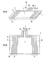
- Fig. 2A and Fig. 2B are illustrations that show a structure of an antenna coil 20 according to the first preferred embodiment.
- Fig. 2A is a perspective view thereof
- Fig. 2B is a developed plan view that shows a structure of a flexible substrate before it is wound on a magnetic core.
- the antenna coil 20 includes a magnetic core 4 and a single flexible substrate 5 wound around the magnetic core 4.
- a ferrite core that preferably has a rectangular or substantially rectangular main surface of about 30 mm in a horizontal direction and about 10 mm in a vertical direction thereof and having a thickness of about 1.5 mm is preferably used in the magnetic core 4, for example.
- a polyimide film for example, is suited for the flexible substrate 5.
- a bendable electric insulating film such as a resin film (e.g., a glass epoxy film) can also be used.
- a conductor is provided on the surface of the flexible substrate 5.
- the conductor preferably defines and includes a first coil portion 2a and a second coil portion 2b around the magnetic core 4.
- the first coil portion 2a includes, for example, a first coil 21 including 6 turns of about 1 mm pitch in the vicinity of the left edge of the magnetic core 4 such that the first coil 21 is arranged at and inside the position about 1 mm in from the left edge of the magnetic core 4.
- the second coil portion 2b includes, for example, a second coil 22 including 6 turns of about 1 mm pitch in the vicinity of the right edge of the magnetic core 4 such that the second coil 22 is arranged at and inside the position about 1 mm in from the right edge of the magnetic core 4.
- the winding direction of the first coil 21 to the coil axis is opposite to that of the second coil 22.
- the flexible substrate 5 includes a projection 6 located at an intermediate position of one longer side thereof. At the projection 6, both ends of the first coil 21 are drawn out as first connections 21a and 21b, and similarly, both ends of the second coil 22 are drawn out as second connections 22a and 22b.
- the flexible substrate 5 includes a conductor-free portion 8 between the first coil portion 2a and the second coil portion 2b.
- each of the conductor sections is illustrated with a single line, the conductor section preferably has a width of about 0.5 mm to about 1 mm and a thickness of about 0.01 mm to about 0.05 mm in actuality, for example.
- each of the conductor sections is in contact with the lower end of the flexible substrate 5, but is separated from the upper end thereof.
- These conductor sections are formed by, for example, screen printing.
- the flexible substrate 5 illustrated in Fig. 2B is bent so as to sandwich the magnetic core 4 such that the upper ends of the conductor sections and the lower ends thereof overlap each other and so as to arrange the surface where the conductor sections are formed outside.
- the overlapping points for example, the point P1 and point P2 indicated by circles in Fig. 2B are electrically connected together by, for example, soldering. This forms the conductor sections as a continuous coil. Because the flexible substrate 5 is significantly thin, even if the overlapping points are not directly bonded together, these points can be electrically connected through the flexible substrate 5.
- the antenna coil 20 illustrated in Fig. 2A and Fig. 2B are mounted to a circuit board, and the first connections 21a and 21b and the second connections 22a and 22b at the projection 6 of the flexible substrate 5 are connected to a wiring pattern on the circuit board.
- the first coil 21 and the second coil 22 are connected in series or parallel in a direction in which induced voltages are added, in accordance with the wiring pattern.
- the inner end of the first coil 21 and the inner end of the second coil 22, i.e., the first connection 21b and the second connection 22b are connected.
- the inner end of the first coil 21 and the outer end of the second coil 22, and the outer end of the first coil 21 and the inner end of the second coil 22, i.e., the first connection 21b and the second connection 22a are connected, and the first connection 21a and the second connection 22b are connected.
- induced voltages occurring in the first coil 21 and the second coil 22 can be added.
- the conductor-free portion 8 is configured to have a sufficient size.
- it is necessary for the magnetic flux intruding into the conductor-free portion 8 to pass through the magnetic core 4 toward the opposite ends thereof it is also required that a structure in which too large of an area of the conductor-free portion 8 causes difficulty in guiding the magnetic flux to the opposite ends of the magnetic core 4 be avoided.
- the opposite ends of the magnetic core 4 on which the magnetic flux is focused are formed as the first coil portion 2a and the second coil portion 2b, thus resulting in a structure in which the magnetic flux intruding into the magnetic core 4 from the conductor-free portion 8 facilitates the first coil 21 and the second coil 22 to induce voltage.
- first coil 21 and the second coil 22 are not connected on the flexible substrate 5, it is possible to change characteristics in accordance with a connecting method even after the antenna coil 20 is produced.
- the series resistance is smaller and the Q factor is larger than those occurring when they are connected in series. If the first coil 21 and the second coil 22 are connected in parallel on the flexible substrate 5, the pattern will be complicated. However, connecting them on the circuit board raises no such problem.
- the first coil 21 and the second coil 22 preferably are symmetrically arranged with respect to the magnetic core 4. Therefore, the magnetic fluxes intruding into both the coils can be the same. Because the number of turns and the coil axis of the first coil 21 is the same as those of the second coil 22, a voltage induced in the first coil 21 and that in the second coil 22 can be the same.
- the magnetic core 4 preferably has a rectangular parallelepiped shape, for example.
- the present invention is not limited to this preferred embodiment, so the magnetic core 4 may be in the form of a polygonal column or a circular cylinder, or other suitable shape.
- the size of the first coil 21 and the number of turns in the first coil 21 may be different from those of the second coil 22. If the number of turns in the second coil 22 is larger than that in the first coil 21, a voltage induced in the second coil 22 is larger than that in the first coil 21.
- This configuration enables linkage not only to the magnetic flux perpendicular to the direction of the coil axis of the antenna coil but also to the magnetic flux parallel with the direction of the coil axis of the antenna coil. That is, when the magnetic flux parallel with the direction of the coil axis with respect to the antenna coil passes, a voltage induced in the first coil 21 and that in the second coil 22 are opposite to each other. However, the induced voltages have different magnitudes, so they are not fully cancelled. Therefore, even when magnetic flux parallel with the direction of the coil axis of the antenna coil intrudes, the magnetic flux enables communications.
- the coil axis of the first coil 21 coincides with that of the second coil 22.
- magnetic flux perpendicular to the direction of the coil axis of the antenna coil can be guided to each coil portion.
- the flexible substrate 5 in producing the antenna coil 20, can also be bent such that the surface where the conductor sections are formed is arranged inside. In this case, the conductor sections are not exposed at the front surface of the antenna coil 20, so the antenna coil has the structure in which the conductor sections are less prone to peeling off.
- the flexible substrate 5 includes the projection 6 used for drawing the first and second coil connections.
- connection between the coil connections and the wiring pattern of the circuit board is not limited to this preferred embodiment.
- the winding direction of the first coil 21 to the coil axis is opposite to that of the second coil 22.
- the winding directions may be the same as long as the coils are connected using the wiring pattern of the circuit board to which the antenna coil is mounted such that induced voltages are added.
- the resonant frequency of a resonant circuit defined by the inductance value of the antenna coil and the capacitance value of a capacitor match with the frequency of a communication signal.
- adjustment (trimming) of the inductance value of the antenna coil is necessary in general.
- the use of a magnetic core that has relative permeability equal to or larger than 100 can provide satisfactory characteristics of communications without adjustment.
- the L (inductance) value increases with an increase in permeability of the magnetic core, when the relative permeability exceeds 100, the rate of change in L value decreases and it is in saturation. Therefore, when an antenna coil is produced such that the target value of relative permeability exceeds 100, even if the relative permeability of the magnetic core of the actually produced antenna coil varies in a wide range from 100, the L value falls within a given range. Specifically, in order to stabilize characteristics of communications of the antenna coil, it is preferable to restrict variations in the L value to approximately ⁇ 1%. However, even if the relative permeability of the magnetic core of the antenna coil produced such that the target value of the relative permeability is 100 varies in a range of about ⁇ 10%, variations in the L value can be restricted to a range of about ⁇ 1%.
- the following table shows results of an investigation of a relationship between the inductance value L of an antenna coil in which a 5-turn first coil is arranged in one end of a magnetic core of 40 ⁇ 10 ⁇ 1 [mm] and a 5-turn second coil is arranged in the other end thereof with respect to relative permeability ⁇ of the magnetic core and its variations.
- ⁇ Center Value of L ⁇ for -1% of L Value ⁇ for +1% of L Value 60 1.166 56.5(-3.5) 64.0(+4.0) 80 1.215 74.2(-5.8) 86.5(+6.5) 100 1.246 90.7(-9.3) 111.8(+11.8)
- Fig. 8 illustrates a range of relative permeability ⁇ for ⁇ 1% of the above inductance value L.
- ⁇ has a range of about 21.1. Accordingly, it is possible to restrict variations in inductance value to about ⁇ 1% or less merely by the use of the magnetic core in which variations in permeability are approximately 20%, so this obviates the necessity to trim the inductance value.
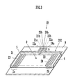
- Fig. 3 is a perspective view that illustrates a structure of an antenna device 10 according to the second preferred embodiment:
- Fig. 4 is a developed plan view that illustrates a flexible substrate before the flexible substrate is wound on a magnetic core of an antenna coil defining a portion of the antenna device.
- the antenna device 10 illustrated in Fig. 3 is preferably formed by mounting of an antenna coil 202 to a circuit board 9.
- the antenna coil 202 includes a magnetic core 4 and a single flexible substrate 5 wound around the magnetic core 4.
- a conductor is provided on the surface of the flexible substrate 5.
- the conductor defines a first coil portion 2a and a second coil portion 2b around the magnetic core 4.
- the first coil portion 2a includes, for example, a third coil 23 including 4 turns and a first coil 21 including 3 turns at about 2 mm pitch from the location about 1 mm inside the left edge of the magnetic core 4.
- the second coil portion 2b includes, for example, a fourth coil 24 including 4 turns and a second coil 22 including 3 turns at about 2 mm pitch from the location about 1 mm inside the right edge of the magnetic core 4.
- the winding direction of the first coil 21 to the coil axis is opposite to that of the second coil 22.
- the winding direction of the third coil 23 to the coil axis is opposite to that of the fourth coil 24.
- the flexible substrate 5 includes a projection 6 formed in an intermediate position of one longer side thereof.
- both ends of the first coil 21 are drawn out as first connections 21a and 21b, and similarly, both ends of the second coil 22 are drawn out as second connections 22a and 22b.
- Both ends of the third coil 23 are drawn out as third connections 23a and 23b.
- both ends of the fourth coil 24 are drawn out as fourth connections 24a and 24b.
- the flexible substrate 5 includes a conductor-free portion 8 between the first coil portion 2a and the second coil portion 2b.
- the flexible substrate 5 illustrated in Fig. 4 is bent so as to sandwich the magnetic core 4 such that the upper ends of the conductor sections and the lower ends thereof overlap each other and so as to arrange the surface where the conductor sections are located outside.
- the overlapping points are electrically connected together by, for example, soldering. This forms the conductor sections as a continuous coil.
- Structures of the other components preferably are substantially the same as those in the first preferred embodiment.
- the antenna coil 202 illustrated in Fig. 3 is mounted to the circuit board 9, and the first connections 21a and 21b, the second connections 22a and 22b, the third connections 23a and 23b, and the fourth connections 24a and 24b at the projection 6 of the flexible substrate 5 are connected to a wiring pattern on the circuit board.
- the set of the first and second coils is used as a receiving antenna, and the set of the third and fourth coils is used as a transmitting antenna.
- the first coil 21 and the second coil 22 are connected in series or parallel using the wiring pattern of the circuit board in a direction in which induced voltages are added.
- the third coil 23 and the fourth coil 24 are connected in series or parallel in a direction in which induced voltages are added.
- the set of the first and second coils is used as a receiving antenna.
- the set of the third and fourth coils is used as a transmitting antenna.
- Providing a receiving antenna and a transmitting antenna independently obviates the necessity to switch the antenna coil using a control circuit between a case where it functions as the one for reception and a case where it functions as the one for transmission.
- the first coil portion 2a preferably includes an arrangement of the first coil 21 and the third coil 23 in an alternating manner
- the second coil portion 2b includes an arrangement of the second coil 22 and the fourth coil 24 in an alternating manner. Therefore, all of a total of four coils can be disposed on a single side of the flexible substrate. Accordingly, the cost of the flexible substrate 5 can be reduced. Alternately arranging the coils allows the coil unit for transmission and the coil unit for reception to be located in substantially the same region. Therefore, the position that can provide the highest sensitivity when the antenna device is held over a reader/writer for reception and that for transmission can be the same. Of course, two coils for transmission and another two coils for reception may be disposed on different surfaces of the flexible substrate. In this case, the cost of the flexible substrate 5 is increased, but the region for the first coil portion 2a and the region for the second coil portion 2b can be reduced.
- a structure of an antenna device according to a third preferred embodiment will be described with reference to Fig. 5 .
- Fig. 5 is a perspective view that illustrates a structure of an antenna device 101 according to the third preferred embodiment.
- the antenna device 101 is preferably formed by mounting of an antenna coil 203 to a circuit board 9.
- the antenna coil 203 includes a first core piece 4a, a second core piece 4b, and a flexible substrate 5 wound around the first core piece 4a and the second core piece 4b.
- a ferrite plate having, for example, a substantially rectangular main surface of about 8 mm in a horizontal direction and about 10 mm in a vertical direction and a thickness of about 1.5 mm is preferably used in each of the first core piece 4a and the second core piece 4b.
- the side of the main surface in the horizontal direction of the first core piece 4a and that in the vertical direction are collinear.
- the distance between the first core piece 4a and the second core piece 4b was about 24 mm.
- a conductor-free portion 8 is provided between the first core piece 4a and the second core piece 4b, which are arranged in such a way.
- a first coil portion 2a and a second coil portion 2b are defined by conductor sections on the surface of the flexible substrate 5 around the first core piece 4a and the second core piece 4b, respectively.
- the first coil portion 2a includes, for example, a third coil 23 including 4 turns and a first coil 21 including 3 turns at about 2 mm pitch from the location about 1 mm inside the left edge of the first core piece 4a.
- the second coil portion 2b includes, for example, a fourth coil 24 including 4 turns and a second coil 22 including 3 turns at about 2 mm pitch from the location about 1 mm inside the right edge of the second core piece 4b.
- the winding direction of the first coil 21 to the coil axis is opposite to that of the second coil 22. Similarly, the winding direction of the first coil 21 to the coil axis is opposite to that of the second coil 22.
- the coil axis of each coil in the first coil portion 2a and that in the second coil portion 2b are parallel or substantially parallel with a horizontal direction of the first core piece 4a and that of the second core piece 4b, respectively.
- the inner end of the third coil 23 and the inner end of the fourth coil 24 are connected by a connecting conductor 25 on the surface of the flexible substrate 5. Additionally, the connecting conductor 25 includes two inductance adjustment conductors 26 and 27.
- the flexible substrate 5 includes a projection 6 located at an intermediate position of one longer side thereof. At the projection 6, both ends of the first coil 21 are drawn out as first connections 21a and 21b, and similarly, both ends of the second coil 22 are drawn out as second connections 22a and 22b. A single end of the third coil 23 is drawn out as a third connection 23a. Similarly, a single end of the fourth coil 24 is drawn out as a fourth connection 24a.
- Structures of the other components preferably are substantially the same as those in the first and second preferred embodiments.
- the inductance adjustment conductor 26 preferably includes three current paths 26a, 26b, and 26c. Three different current paths are selectable by maintaining one path and trimming (disconnecting) the other two paths among them.
- the inductance adjustment conductor 27 includes three current paths 27a, 27b, and 27c. Three different current paths are selectable by maintaining one path and trimming (disconnecting) the other two paths among them. Selecting a combination of these current paths can adjust the inductance of the antenna coil unit for the set of the third and fourth coils.
- the outer end of the first core piece 4a is provided with a magnetic-core bend 4ac extending in a direction that is perpendicular or substantially perpendicular to the direction of the coil axis.
- the outer end of the second core piece 4b is provided with a bend 4bc.
- Each of the bends 4ac and 4bc is made of ferrite, as in the case of the first core piece 4a and the second core piece 4b.
- the bends 4ac and 4bc are bonded to the end of the first core piece 4a and that of the bend 4bc, respectively.
- the provision of the bends 4ac and 4bc increases the cross-sectional area of each of the first and second core pieces in a direction perpendicular or substantially perpendicular to the circuit board 9 at the respective ends of the first and second core pieces. Therefore, the magnetic reluctance in the end of the antenna coil 203 in the direction of the coil axis can be reduced.
- the magnetic-core bends 4ac and 4bc are arranged outside the opposite ends of the circuit board 9 when the antenna coil 203 is mounted to the circuit board 9. This configuration avoids the magnetic-core bends 4ac and 4bc from being affected by the conductor provided on the circuit board 9, the magnetic reluctance in the end of the antenna coil 203 in the direction of the coil axis can be further reduced. Accordingly, the flux gathering effect of the antenna coil is improved, so the antenna device can have high communication sensitivity. Because the antenna coil 203 can be formed so as to be fitted with the shape of the circuit board 9, the antenna device 101 including the antenna coil 203 and the circuit board 9 can be miniaturized.
- each of the bends 4ac and 4bc is not limited to a rectangular parallelepiped and can be any suitable shape.
- the magnetic core divided into the first core piece 4a and the second core piece 4b was preferably used. It is believed that the antenna sensitivity is not reduced even when the conductor-free portion 8 for allowing intrusion of magnetic flux has no magnetic core. Therefore, the division of the magnetic core reduces the volume of the antenna coil, so the size and weight of the antenna coil can be reduced while the antenna sensitivity is maintained.
- a structure of an antenna device according to a fourth preferred embodiment will be described with reference to Fig. 6 .
- Fig. 6 illustrates a structure of an antenna coil 204 according to the fourth preferred embodiment.
- Fig. 6 is a developed plan view that shows a structure of a flexible substrate before the flexible substrate is wound on a magnetic core and also illustrates a portion of a conductor pattern on a circuit board to which the antenna coil is to be mounted.
- the magnetic core preferably is substantially the same as in the first and second preferred embodiments, so it is omitted in the drawing.
- the antenna coil 204 includes a single flexible substrate 5 to be wound around the magnetic core.
- a conductor is provided on the surface of the flexible substrate 5.
- the conductor defines a first coil portion 2a and a second coil portion 2b around the magnetic core.
- the first coil portion 2a includes, for example, a first coil 21 including 2 turns and a third coil 23 including 8 turns.
- the second coil portion 2b includes, for example, a second coil 22 including 2 turns and a fourth coil 24 including 8 turns.
- the winding direction of the first coil 21 to the coil axis is opposite to that of the second coil 22.
- the winding direction of the third coil 23 to the coil axis is opposite to that of the fourth coil 24.
- the flexible substrate 5 includes a projection 6 located at an intermediate position of one longer side thereof. At the projection 6, both ends of the first coil 21 and both ends of the second coil 22 are drawn out. A single outer end of the third coil 23 and that of the fourth coil 24 and a single inner end of the inductance adjustment conductor 26 and that of the inductance adjustment conductor 27 are drawn out.
- Each of the inductance adjustment conductors 26 and 27 preferably includes three current paths. Selectively trimming the current paths produces combinations of the current paths. The selection enables the adjustment of the inductance of the antenna coil unit for the set of the third coil 23 and the fourth coil 24.
- Structures of the other components preferably are substantially the same as those in the first to third preferred embodiments.
- the wiring pattern illustrated outside the flexible substrate 5 is a wiring pattern provided on a circuit board to which the antenna coil 204 is to be mounted.
- This wiring pattern on the circuit board connects the inner end of the first coil 21 to the inner end of the second coil 22. That is, the first coil and the second coil are connected in series.
- the inner end of the inductance adjustment conductor 27 is connected to the outer end of the third coil 23, and the inner end of the inductance adjustment conductor 26 is connected to the outer end of the fourth coil 24. That is, the third coil and the fourth coil are connected in parallel.
- eight terminals of the coil connections of the antenna coil 204 are converted into four terminals on the circuit board.
- the set of the first and second coils is used as a transmitting antenna
- the set of the third and fourth coils is used as a receiving antenna.
- an antenna coil unit for reception and an antenna coil unit for transmission can be freely formed by the use of the wiring pattern on the circuit board to which the antenna coil is mounted.
- the circuit board is typically a multilayer wiring board, for example. Accordingly, it is fairly easy to connect the third coil and the fourth coil using a wiring pattern on the circuit board.
- a structure of an antenna device according to a fifth preferred embodiment will be described with reference to Fig. 7 .
- Fig. 7 illustrates a structure of an antenna coil 205 according to the fifth preferred embodiment.
- Fig. 7 is a developed plan view that shows a structure of a flexible substrate before the flexible substrate is wound on a magnetic core and also illustrates a portion of a conductor pattern on a circuit board to which the antenna coil is to be mounted.
- the magnetic core is substantially the same as in the first, second and fourth preferred embodiments, so it is omitted in the drawing.
- the antenna coil 205 includes a single flexible substrate 5 to be wound around the magnetic core.
- a conductor is provided on the surface of the flexible substrate 5.
- the conductor defines a first coil portion 2a and a second coil portion 2b around the magnetic core.
- the first coil portion 2a includes, for example, a first coil 21 including 2.5 turns and a third coil 23 including 8 turns.
- the second coil portion 2b includes, for example, a second coil 22 including 2.5 turns and a fourth coil 24 including 8 turns.
- the winding direction of the first coil 21 to the coil axis is opposite to that of the second coil 22.
- the winding direction of the third coil 23 to the coil axis is opposite to that of the fourth coil 24.
- the inner end of the first coil 21 and the inner end of the second coil 22 are electrically connected using a connecting conductor 25.
- the flexible substrate 5 includes a projection 6 located at an intermediate position of one longer side thereof. At the projection 6, a single outer end of the first coil 21 and that of the second coil 22 are drawn out. A single outer end of the third coil 23 and that of the fourth coil 24 and a single inner end of the inductance adjustment conductor 26 and that of the inductance adjustment conductor 27 are drawn out.
- Structures of the other components preferably are substantially the same as those in the first to fourth preferred embodiments.
- the wiring pattern illustrated outside the flexible substrate 5 is a wiring pattern disposed on a circuit board to which the antenna coil 205 is to be mounted.
- This wiring pattern on the circuit board connects the inner end of the inductance adjustment conductor 27 to the outer end of the third coil 23 and connects the inner end of the inductance adjustment conductor 26 to the outer end of the fourth coil 24. That is, the third and fourth coils are connected in parallel. In such a way, six terminals of the coil connections of the antenna coil 205 are converted into four terminals on the circuit board.
- the set of the first and second coils is used as a transmitting antenna
- the set of the third and fourth coils is used as a receiving antenna.
- an antenna coil unit for reception and an antenna coil unit for transmission can be freely formed by the use of the wiring pattern on the circuit board to which the antenna coil is mounted.
Landscapes
- Details Of Aerials (AREA)
- Support Of Aerials (AREA)
Abstract
An antenna device is constructed such that an antenna coil (202) including a magnetic core (4) and a flexible substrate (5) is mounted to a circuit board (9). A first coil portion (2a) having a coil axis parallel with a main surface of the magnetic core (4) includes a first coil (21) and a third coil (23). A second coil portion (2b) includes a second coil (22) and a fourth coil (24). A conductor-free portion (8) is located between the first and second coil portions (2a, 2b). The flexible substrate (5) includes a projection (6), and first to fourth coil connections are drawn out at the projection (6). The antenna device is constructed such that each of the coils is connected on the circuit board by connecting to a conductor pattern on the circuit board (9) at the projection (6) of the flexible substrate (5).
Description
- The present invention relates to an antenna coil mounted to a board for use in a radio frequency identification (RFID) system that communicates with an external apparatus using an electromagnetic signal and to an antenna device including the antenna coil.
- In RFID systems, which are being increasingly used in recent years, a mobile electronic device (e.g., a mobile phone) and a reader/writer both have an antenna for information communications mounted therein and exchange data therebetween.
- An antenna coil for use in a tag employing the RFID technique is disclosed in
Patent Document 1.Fig. 1 is an illustration that shows an example structure of an antenna coil described inPatent Document 1. In thisantenna coil 11, an electricalinsulating film 13 includingconductors magnetic core member 12 is sandwiched, and the ends are connected to form a coil. The use of an electrical insulating film in such a way enables the antenna coil to have a structure that is thinner than that in which a conductor is wound around a magnetic core member. - Patent Document 1: Japanese Unexamined Patent Application Publication No.
2002-252518 - However, if the antenna coil described in
Patent Document 1 is embedded in a mobile phone while the main surface of the antenna coil is arranged so as to be parallel with the main surface of the mobile phone, because the coil axis of the coil is parallel with the main surface of the mobile phone and the main surface of the antenna coil has no portion for allowing an intrusion of magnetic flux, only magnetic flux from the side of the antenna coil will pass through the coil axis of the antenna coil. Therefore, in actuality, communications cannot be performed. In order to utilize the antenna coil described inPatent Document 1 in a mobile phone, it is necessary to arrange the antenna coil in a direction perpendicular to the main surface of the mobile phone. Such a structure cannot allow the antenna coil to be used as one that can be mounted on a circuit board, and a structure for embedding and an operation therefor are inevitably complicated. - In view of the above, preferred embodiments of the present invention provide an antenna coil mounted to a board and a highly sensitive antenna device including the antenna coil, the antenna coil allowing communications to be performed while magnetic flux intrudes into the antenna coil from a direction perpendicular or substantially perpendicular to the main surface of the antenna coil and being readily embeddable in an electronic apparatus.
-
- (1) An antenna coil mounted to a board according to a preferred embodiment of the present invention includes:
- a flat-shaped magnetic core;
- a flexible substrate wound around the magnetic core, a conductor provided on a surface of the flexible substrate;
- a first coil portion defined by the conductor and having a coil axis parallel or substantially parallel with a main surface of the magnetic core;
- a second coil portion defined by the conductor and having a coil axis parallel or substantially parallel with the main surface of the magnetic core, the second coil portion being paired with the first coil portion;
- a first coil connection defined by the conductor and being part of the first coil portion; and
- a second coil connection defined by the conductor and being part of the second coil portion,
- wherein the flexible substrate includes a conductor-free portion where the conductor is not formed, the conductor-free portion being disposed between the first coil portion and the second coil portion.
- (2) Two sets of coils may be provided by configuring the first coil portion including a first coil and a third coil and configuring the second coil portion including a second coil paired with the first coil and a fourth coil paired with the third coil.
- (3) The flexible substrate may be provided with a connecting conductor that connects inner ends of the first and second coils or inner ends of the third and fourth coils in advance and is defined by the conductor.
- (4) Preferably, the coil portions may be arranged on the flexible substrate such that conductor sections defining the first coil and the third coil may be alternately arranged and conductor sections defining the second coil and the fourth coil may be alternately arranged.
- (5) Preferably, the flexible substrate may include a projection, and each of the first and second coil connections may be located at the projection.
- (6) The magnetic core may preferably include a first core piece and a second core piece. The first coil portion may be arranged around the first core piece. The second coil portion may be arranged around the second core piece.
- (7) The magnetic core may be bent at an end thereof in a direction in which the first coil portion and the second coil portion are aligned.
- (8) An antenna device according to a preferred embodiment of the present invention includes the antenna coil mounted to a board and a circuit board having a wiring pattern to be connected to each of the coil connection of the first coil portion and the coil connection of the second coil portion. The antenna device is preferably arranged such that the antenna coil is mounted to the circuit board in such a way that a main surface of the antenna coil and a main surface of the circuit board are parallel or substantially parallel with each other.
- According to various preferred embodiments of the present invention, the following advantages are provided.
- (1) The use of the flexible substrate in forming the coil enables the antenna coil to have a reduced thickness. The structure that allows magnetic flux to intrude into the conductor-free portion disposed between the first coil portion and the second coil portion enables communications to be performed while magnetic flux intrudes from a direction perpendicular or substantially perpendicular to the main surface of the antenna coil.
The first coil portion and the second coil portion are not connected on the flexible substrate, but they are connected using wiring connected to the connection of each of the first coil portion and the second coil portion on the circuit board. Thus, for example, the first coil portion and the second coil portion are connectable both in series and in parallel. Accordingly, the characteristics of the antenna coil can be changed in accordance with circuit design. If the first and second coils are connected in parallel using conductor wiring disposed on the flexible substrate, the pattern will be significantly complicated. However, when the first and second coils are connected on the circuit board to which the antenna coil is mounted, a simple pattern is sufficient. - (2) The provision of the two sets of coils such that the first coil portion includes the first coil and the third coil, and the second coil portion includes the second coil paired with the first coil and the fourth coil paired with the third coil obviates the necessity to switch one set of coils between the one for reception and the one for transmission and can optimize an antenna coil unit for transmission and that for reception, so high sensitivity is achieved.
- (3) The provision of the connecting conductor connecting the inner ends of the first and second coils or the inner ends of the third and fourth coils on the flexible substrate enables the first and second coils or the third and fourth coils to be connected in series and also the number of terminals for connecting to the circuit board to be reduced. The adjustment of the connecting conductor by trimming enables the inductance of the antenna coil by the use of the first and second coils or the third and fourth coils.
- (4) The arrangement of the conductor sections defining the first and second coils and the conductor sections defining the third and fourth coils are alternately arranged, respectively, enables the position that can provide the highest sensitivity when the antenna device is held over a reader/writer for reception and that for transmission to be the same when one set of the first and second coils and the third and fourth coils is used as a reception coil unit and the other set of first and second coils and the third and fourth coils is used as a transmission coil unit.
- (5) The provision of the projection on the flexible substrate enables each coil in each of the first and second coil portions to be readily and easily connected to a wiring pattern provided on the circuit board.
- (6) An experiment conducted by the inventors reveals that, even if no magnetic core is present in the conductor-free portion disposed between the first coil portion and the second coil portion, it does not affect the antenna sensitivity (communication distance). Therefore, the division of the magnetic core into the first core piece and the second core piece reduces the volume of the antenna coil, so the size and weight of the antenna coil can be reduced while the antenna sensitivity is maintained.
- (7) The structure in which the magnetic core is bent at the end in the direction in which the first coil portion and the second coil portion are aligned increases the cross-sectional area of the end in the direction of the coil axis of the antenna coil and reduces the magnetic reluctance occurring when the magnetic flux radiates. Therefore, the antenna sensitivity can be improved.
- (8) Connecting the antenna coil mounted to a board and a circuit on the circuit board and connecting the coils can be readily performed merely by mounting of the antenna coil to the circuit board.
-
-
Fig. 1 is an illustration that shows an example structure of an antenna coil described inPatent Document 1. -
Fig. 2A and Fig. 2B are illustrations that show a structure of an antenna coil mounted to a board according to a first preferred embodiment of the present invention. -
Fig. 3 is a perspective view that shows a structure of an antenna device according to a second preferred embodiment of the present invention. -
Fig. 4 is another illustration that shows a structure of the antenna coil mounted to a board according to the second preferred embodiment of the present invention. -
Fig. 5 is an illustration that shows a structure of an antenna device according to a third preferred embodiment of the present invention. -
Fig. 6 is an illustration that shows a structure of an antenna coil mounted to a board according to a fourth preferred embodiment of the present invention. -
Fig. 7 is an illustration that shows a structure of an antenna coil mounted to a board according to a fifth preferred embodiment of the present invention. -
Fig. 8 is an illustration that shows a range of relative permeability µ of a magnetic core for ±1% of inductance value L of the antenna coil. -
- 2a
- first coil portion
- 2b
- second coil portion
- 4
- magnetic core
- 4a
- first core piece
- 4b
- second core piece
- 4ac, 4bc
- bend
- 5
- flexible substrate
- 6
- projection
- 8
- conductor-unformed portion
- 9
- circuit board
- 10, 101
- antenna device
- 20, 202, 203, 204, 205
- antenna coil mounted to board
- 21
- first coil
- 21a, 21b
- first coil connection
- 22
- second coil
- 22a, 22b
- second coil connection
- 23
- third coil
- 24
- fourth coil
- 25
- connecting conductor
- 26, 27
- inductance adjustment conductor
- A structure of an antenna coil mounted to a board (hereinafter referred to simply as an antenna coil) according to a first preferred embodiment is described with reference to
Fig. 2A andFig. 8 . -
Fig. 2A and Fig. 2B are illustrations that show a structure of anantenna coil 20 according to the first preferred embodiment.Fig. 2A is a perspective view thereof, andFig. 2B is a developed plan view that shows a structure of a flexible substrate before it is wound on a magnetic core. - As illustrated in
Fig. 2A and Fig. 2B , theantenna coil 20 according to the first preferred embodiment includes amagnetic core 4 and a singleflexible substrate 5 wound around themagnetic core 4. - A ferrite core that preferably has a rectangular or substantially rectangular main surface of about 30 mm in a horizontal direction and about 10 mm in a vertical direction thereof and having a thickness of about 1.5 mm is preferably used in the
magnetic core 4, for example. - A polyimide film, for example, is suited for the
flexible substrate 5. Aside from it, a bendable electric insulating film, such as a resin film (e.g., a glass epoxy film) can also be used. A conductor is provided on the surface of theflexible substrate 5. The conductor preferably defines and includes afirst coil portion 2a and asecond coil portion 2b around themagnetic core 4. Specifically, thefirst coil portion 2a includes, for example, afirst coil 21 including 6 turns of about 1 mm pitch in the vicinity of the left edge of themagnetic core 4 such that thefirst coil 21 is arranged at and inside the position about 1 mm in from the left edge of themagnetic core 4. Similarly, thesecond coil portion 2b includes, for example, asecond coil 22 including 6 turns of about 1 mm pitch in the vicinity of the right edge of themagnetic core 4 such that thesecond coil 22 is arranged at and inside the position about 1 mm in from the right edge of themagnetic core 4. The winding direction of thefirst coil 21 to the coil axis is opposite to that of thesecond coil 22. - The
flexible substrate 5 includes aprojection 6 located at an intermediate position of one longer side thereof. At theprojection 6, both ends of thefirst coil 21 are drawn out asfirst connections second coil 22 are drawn out assecond connections - The
flexible substrate 5 includes a conductor-free portion 8 between thefirst coil portion 2a and thesecond coil portion 2b. - In
Fig. 2B , six conductor sections, for example, are provided in the vicinity of each of both right and left ends of theflexible substrate 5 on the surface thereof. Although each of the conductor sections is illustrated with a single line, the conductor section preferably has a width of about 0.5 mm to about 1 mm and a thickness of about 0.01 mm to about 0.05 mm in actuality, for example. InFig. 2B , each of the conductor sections is in contact with the lower end of theflexible substrate 5, but is separated from the upper end thereof. These conductor sections are formed by, for example, screen printing. - The
flexible substrate 5 illustrated inFig. 2B is bent so as to sandwich themagnetic core 4 such that the upper ends of the conductor sections and the lower ends thereof overlap each other and so as to arrange the surface where the conductor sections are formed outside. The overlapping points, for example, the point P1 and point P2 indicated by circles inFig. 2B are electrically connected together by, for example, soldering. This forms the conductor sections as a continuous coil. Because theflexible substrate 5 is significantly thin, even if the overlapping points are not directly bonded together, these points can be electrically connected through theflexible substrate 5. - The
antenna coil 20 illustrated inFig. 2A and Fig. 2B are mounted to a circuit board, and thefirst connections second connections projection 6 of theflexible substrate 5 are connected to a wiring pattern on the circuit board. For the circuit board, thefirst coil 21 and thesecond coil 22 are connected in series or parallel in a direction in which induced voltages are added, in accordance with the wiring pattern. In the present preferred embodiment, because the winding direction of thefirst coil 21 to the coil axis and that of thesecond coil 22 are opposite to each other, in order to connect them in series, the inner end of thefirst coil 21 and the inner end of thesecond coil 22, i.e., thefirst connection 21b and thesecond connection 22b are connected. In order to connect them in parallel, the inner end of thefirst coil 21 and the outer end of thesecond coil 22, and the outer end of thefirst coil 21 and the inner end of thesecond coil 22, i.e., thefirst connection 21b and thesecond connection 22a are connected, and thefirst connection 21a and thesecond connection 22b are connected. By use of such a connection, induced voltages occurring in thefirst coil 21 and thesecond coil 22 can be added. - When communications with a reader/writer for use in an RFID system are performed using the
antenna coil 20 having the unique structure as described above, magnetic flux intrudes into the conductor-free portion 8 of theantenna coil 20 from the reader/writer. Therefore, the conductor-free portion 8 is configured to have a sufficient size. However, because it is necessary for the magnetic flux intruding into the conductor-free portion 8 to pass through themagnetic core 4 toward the opposite ends thereof, it is also required that a structure in which too large of an area of the conductor-free portion 8 causes difficulty in guiding the magnetic flux to the opposite ends of themagnetic core 4 be avoided. In the present preferred embodiment, the opposite ends of themagnetic core 4 on which the magnetic flux is focused are formed as thefirst coil portion 2a and thesecond coil portion 2b, thus resulting in a structure in which the magnetic flux intruding into themagnetic core 4 from the conductor-free portion 8 facilitates thefirst coil 21 and thesecond coil 22 to induce voltage. - Because the
first coil 21 and thesecond coil 22 are not connected on theflexible substrate 5, it is possible to change characteristics in accordance with a connecting method even after theantenna coil 20 is produced. In particular, when thefirst coil 21 and thesecond coil 22 are connected in parallel, the series resistance is smaller and the Q factor is larger than those occurring when they are connected in series. If thefirst coil 21 and thesecond coil 22 are connected in parallel on theflexible substrate 5, the pattern will be complicated. However, connecting them on the circuit board raises no such problem. - In the first preferred embodiment, the
first coil 21 and thesecond coil 22 preferably are symmetrically arranged with respect to themagnetic core 4. Therefore, the magnetic fluxes intruding into both the coils can be the same. Because the number of turns and the coil axis of thefirst coil 21 is the same as those of thesecond coil 22, a voltage induced in thefirst coil 21 and that in thesecond coil 22 can be the same. - In the first preferred embodiment, the
magnetic core 4 preferably has a rectangular parallelepiped shape, for example. However, the present invention is not limited to this preferred embodiment, so themagnetic core 4 may be in the form of a polygonal column or a circular cylinder, or other suitable shape. - The size of the
first coil 21 and the number of turns in thefirst coil 21 may be different from those of thesecond coil 22. If the number of turns in thesecond coil 22 is larger than that in thefirst coil 21, a voltage induced in thesecond coil 22 is larger than that in thefirst coil 21. This configuration enables linkage not only to the magnetic flux perpendicular to the direction of the coil axis of the antenna coil but also to the magnetic flux parallel with the direction of the coil axis of the antenna coil. That is, when the magnetic flux parallel with the direction of the coil axis with respect to the antenna coil passes, a voltage induced in thefirst coil 21 and that in thesecond coil 22 are opposite to each other. However, the induced voltages have different magnitudes, so they are not fully cancelled. Therefore, even when magnetic flux parallel with the direction of the coil axis of the antenna coil intrudes, the magnetic flux enables communications. - In this preferred embodiment, the coil axis of the
first coil 21 coincides with that of thesecond coil 22. However, even if the coil axes do not exactly coincide with each other, magnetic flux perpendicular to the direction of the coil axis of the antenna coil can be guided to each coil portion. - In this preferred embodiment, in producing the
antenna coil 20, theflexible substrate 5 can also be bent such that the surface where the conductor sections are formed is arranged inside. In this case, the conductor sections are not exposed at the front surface of theantenna coil 20, so the antenna coil has the structure in which the conductor sections are less prone to peeling off. - In this preferred embodiment, the
flexible substrate 5 includes theprojection 6 used for drawing the first and second coil connections. However, connection between the coil connections and the wiring pattern of the circuit board is not limited to this preferred embodiment. Additionally, in this preferred embodiment, the winding direction of thefirst coil 21 to the coil axis is opposite to that of thesecond coil 22. However, the winding directions may be the same as long as the coils are connected using the wiring pattern of the circuit board to which the antenna coil is mounted such that induced voltages are added. - When the above-described antenna coil is used in the antenna device for use in communications, it is preferable that the resonant frequency of a resonant circuit defined by the inductance value of the antenna coil and the capacitance value of a capacitor match with the frequency of a communication signal. However, because the resonant frequency varies with variations in permeability of the magnetic core, adjustment (trimming) of the inductance value of the antenna coil is necessary in general. However, as described below, the use of a magnetic core that has relative permeability equal to or larger than 100 can provide satisfactory characteristics of communications without adjustment. Although the L (inductance) value increases with an increase in permeability of the magnetic core, when the relative permeability exceeds 100, the rate of change in L value decreases and it is in saturation. Therefore, when an antenna coil is produced such that the target value of relative permeability exceeds 100, even if the relative permeability of the magnetic core of the actually produced antenna coil varies in a wide range from 100, the L value falls within a given range. Specifically, in order to stabilize characteristics of communications of the antenna coil, it is preferable to restrict variations in the L value to approximately ±1%. However, even if the relative permeability of the magnetic core of the antenna coil produced such that the target value of the relative permeability is 100 varies in a range of about ±10%, variations in the L value can be restricted to a range of about ±1%.
- The following table shows results of an investigation of a relationship between the inductance value L of an antenna coil in which a 5-turn first coil is arranged in one end of a magnetic core of 40×10×1 [mm] and a 5-turn second coil is arranged in the other end thereof with respect to relative permeability µ of the magnetic core and its variations.
µ Center Value of L µ for -1% of L Value µ for +1% of L Value 60 1.166 56.5(-3.5) 64.0(+4.0) 80 1.215 74.2(-5.8) 86.5(+6.5) 100 1.246 90.7(-9.3) 111.8(+11.8) -
Fig. 8 illustrates a range of relative permeability µ for ±1% of the above inductance value L. As described above, when the relative permeability of the magnetic core is at or above 100, µ has a range of about 21.1. Accordingly, it is possible to restrict variations in inductance value to about ±1% or less merely by the use of the magnetic core in which variations in permeability are approximately 20%, so this obviates the necessity to trim the inductance value. - A structure of an antenna device according to a second preferred embodiment will be described with reference to
Figs. 3 and4 . -
Fig. 3 is a perspective view that illustrates a structure of anantenna device 10 according to the second preferred embodiment:Fig. 4 is a developed plan view that illustrates a flexible substrate before the flexible substrate is wound on a magnetic core of an antenna coil defining a portion of the antenna device. - The
antenna device 10 illustrated inFig. 3 is preferably formed by mounting of anantenna coil 202 to acircuit board 9. - The
antenna coil 202 includes amagnetic core 4 and a singleflexible substrate 5 wound around themagnetic core 4. - A conductor is provided on the surface of the
flexible substrate 5. The conductor defines afirst coil portion 2a and asecond coil portion 2b around themagnetic core 4. Specifically, thefirst coil portion 2a includes, for example, athird coil 23 including 4 turns and afirst coil 21 including 3 turns at about 2 mm pitch from the location about 1 mm inside the left edge of themagnetic core 4. Similarly, thesecond coil portion 2b includes, for example, afourth coil 24 including 4 turns and asecond coil 22 including 3 turns at about 2 mm pitch from the location about 1 mm inside the right edge of themagnetic core 4. - The winding direction of the
first coil 21 to the coil axis is opposite to that of thesecond coil 22. The winding direction of thethird coil 23 to the coil axis is opposite to that of thefourth coil 24. - The
flexible substrate 5 includes aprojection 6 formed in an intermediate position of one longer side thereof. At theprojection 6, both ends of thefirst coil 21 are drawn out asfirst connections second coil 22 are drawn out assecond connections third coil 23 are drawn out asthird connections fourth coil 24 are drawn out asfourth connections - The
flexible substrate 5 includes a conductor-free portion 8 between thefirst coil portion 2a and thesecond coil portion 2b. - The
flexible substrate 5 illustrated inFig. 4 is bent so as to sandwich themagnetic core 4 such that the upper ends of the conductor sections and the lower ends thereof overlap each other and so as to arrange the surface where the conductor sections are located outside. The overlapping points are electrically connected together by, for example, soldering. This forms the conductor sections as a continuous coil. - Structures of the other components preferably are substantially the same as those in the first preferred embodiment.
- The
antenna coil 202 illustrated inFig. 3 is mounted to thecircuit board 9, and thefirst connections second connections third connections fourth connections projection 6 of theflexible substrate 5 are connected to a wiring pattern on the circuit board. The set of the first and second coils is used as a receiving antenna, and the set of the third and fourth coils is used as a transmitting antenna. - When communications with a reader/writer for use in an RFID system are performed using the
antenna device 10 structured in the above-described way, magnetic flux intrudes into the conductor-free portion 8 of theantenna coil 202 from the reader/writer. The magnetic flux not only passes across themagnetic core 4 but also is blocked by the conductor sections on the circuit board, thus changes its path, and passes through the coil axis of each of the first tofourth coils 21 to 24. - By connecting the connections at the
projection 6 to the circuit board, thefirst coil 21 and thesecond coil 22 are connected in series or parallel using the wiring pattern of the circuit board in a direction in which induced voltages are added. Similarly, thethird coil 23 and thefourth coil 24 are connected in series or parallel in a direction in which induced voltages are added. The set of the first and second coils is used as a receiving antenna. The set of the third and fourth coils is used as a transmitting antenna. - Providing a receiving antenna and a transmitting antenna independently obviates the necessity to switch the antenna coil using a control circuit between a case where it functions as the one for reception and a case where it functions as the one for transmission.
- In this preferred embodiment, the
first coil portion 2a preferably includes an arrangement of thefirst coil 21 and thethird coil 23 in an alternating manner, and thesecond coil portion 2b includes an arrangement of thesecond coil 22 and thefourth coil 24 in an alternating manner. Therefore, all of a total of four coils can be disposed on a single side of the flexible substrate. Accordingly, the cost of theflexible substrate 5 can be reduced. Alternately arranging the coils allows the coil unit for transmission and the coil unit for reception to be located in substantially the same region. Therefore, the position that can provide the highest sensitivity when the antenna device is held over a reader/writer for reception and that for transmission can be the same. Of course, two coils for transmission and another two coils for reception may be disposed on different surfaces of the flexible substrate. In this case, the cost of theflexible substrate 5 is increased, but the region for thefirst coil portion 2a and the region for thesecond coil portion 2b can be reduced. - A structure of an antenna device according to a third preferred embodiment will be described with reference to
Fig. 5 . -
Fig. 5 is a perspective view that illustrates a structure of anantenna device 101 according to the third preferred embodiment. - As illustrated in
Fig. 5 , theantenna device 101 according to the third preferred embodiment is preferably formed by mounting of anantenna coil 203 to acircuit board 9. - The
antenna coil 203 includes afirst core piece 4a, asecond core piece 4b, and aflexible substrate 5 wound around thefirst core piece 4a and thesecond core piece 4b. - A ferrite plate having, for example, a substantially rectangular main surface of about 8 mm in a horizontal direction and about 10 mm in a vertical direction and a thickness of about 1.5 mm is preferably used in each of the
first core piece 4a and thesecond core piece 4b. The side of the main surface in the horizontal direction of thefirst core piece 4a and that in the vertical direction are collinear. The distance between thefirst core piece 4a and thesecond core piece 4b was about 24 mm. A conductor-free portion 8 is provided between thefirst core piece 4a and thesecond core piece 4b, which are arranged in such a way. - A
first coil portion 2a and asecond coil portion 2b are defined by conductor sections on the surface of theflexible substrate 5 around thefirst core piece 4a and thesecond core piece 4b, respectively. Specifically, thefirst coil portion 2a includes, for example, athird coil 23 including 4 turns and afirst coil 21 including 3 turns at about 2 mm pitch from the location about 1 mm inside the left edge of thefirst core piece 4a. Similarly, thesecond coil portion 2b includes, for example, afourth coil 24 including 4 turns and asecond coil 22 including 3 turns at about 2 mm pitch from the location about 1 mm inside the right edge of thesecond core piece 4b. - The winding direction of the
first coil 21 to the coil axis is opposite to that of thesecond coil 22. Similarly, the winding direction of thefirst coil 21 to the coil axis is opposite to that of thesecond coil 22. - The coil axis of each coil in the
first coil portion 2a and that in thesecond coil portion 2b are parallel or substantially parallel with a horizontal direction of thefirst core piece 4a and that of thesecond core piece 4b, respectively. - The inner end of the
third coil 23 and the inner end of thefourth coil 24 are connected by a connectingconductor 25 on the surface of theflexible substrate 5. Additionally, the connectingconductor 25 includes twoinductance adjustment conductors - The
flexible substrate 5 includes aprojection 6 located at an intermediate position of one longer side thereof. At theprojection 6, both ends of thefirst coil 21 are drawn out asfirst connections second coil 22 are drawn out assecond connections third coil 23 is drawn out as athird connection 23a. Similarly, a single end of thefourth coil 24 is drawn out as afourth connection 24a. - Structures of the other components preferably are substantially the same as those in the first and second preferred embodiments.
- The
inductance adjustment conductor 26 preferably includes threecurrent paths inductance adjustment conductor 27 includes threecurrent paths - The outer end of the
first core piece 4a is provided with a magnetic-core bend 4ac extending in a direction that is perpendicular or substantially perpendicular to the direction of the coil axis. Similarly, the outer end of thesecond core piece 4b is provided with a bend 4bc. Each of the bends 4ac and 4bc is made of ferrite, as in the case of thefirst core piece 4a and thesecond core piece 4b. The bends 4ac and 4bc are bonded to the end of thefirst core piece 4a and that of the bend 4bc, respectively. The provision of the bends 4ac and 4bc increases the cross-sectional area of each of the first and second core pieces in a direction perpendicular or substantially perpendicular to thecircuit board 9 at the respective ends of the first and second core pieces. Therefore, the magnetic reluctance in the end of theantenna coil 203 in the direction of the coil axis can be reduced. - The magnetic-core bends 4ac and 4bc are arranged outside the opposite ends of the
circuit board 9 when theantenna coil 203 is mounted to thecircuit board 9. This configuration avoids the magnetic-core bends 4ac and 4bc from being affected by the conductor provided on thecircuit board 9, the magnetic reluctance in the end of theantenna coil 203 in the direction of the coil axis can be further reduced. Accordingly, the flux gathering effect of the antenna coil is improved, so the antenna device can have high communication sensitivity. Because theantenna coil 203 can be formed so as to be fitted with the shape of thecircuit board 9, theantenna device 101 including theantenna coil 203 and thecircuit board 9 can be miniaturized. - Such advantages are obtainable not only when the bends 4ac and 4bc are bonded to their respective ends, as in the present preferred embodiment, but also when the bends 4ac and 4bc are formed integrally with the
first core piece 4a and thesecond core piece 4b, respectively. The shape of each of the bends 4ac and 4bc is not limited to a rectangular parallelepiped and can be any suitable shape. - In this preferred embodiment, the magnetic core divided into the
first core piece 4a and thesecond core piece 4b was preferably used. It is believed that the antenna sensitivity is not reduced even when the conductor-free portion 8 for allowing intrusion of magnetic flux has no magnetic core. Therefore, the division of the magnetic core reduces the volume of the antenna coil, so the size and weight of the antenna coil can be reduced while the antenna sensitivity is maintained. - A structure of an antenna device according to a fourth preferred embodiment will be described with reference to
Fig. 6 . -
Fig. 6 illustrates a structure of anantenna coil 204 according to the fourth preferred embodiment.Fig. 6 is a developed plan view that shows a structure of a flexible substrate before the flexible substrate is wound on a magnetic core and also illustrates a portion of a conductor pattern on a circuit board to which the antenna coil is to be mounted. The magnetic core preferably is substantially the same as in the first and second preferred embodiments, so it is omitted in the drawing. - As illustrated in
Fig. 6 , theantenna coil 204 according to the fourth preferred embodiment includes a singleflexible substrate 5 to be wound around the magnetic core. A conductor is provided on the surface of theflexible substrate 5. The conductor defines afirst coil portion 2a and asecond coil portion 2b around the magnetic core. Specifically, thefirst coil portion 2a includes, for example, afirst coil 21 including 2 turns and athird coil 23 including 8 turns. Similarly, thesecond coil portion 2b includes, for example, asecond coil 22 including 2 turns and afourth coil 24 including 8 turns. - The winding direction of the
first coil 21 to the coil axis is opposite to that of thesecond coil 22. The winding direction of thethird coil 23 to the coil axis is opposite to that of thefourth coil 24. -
Inductance adjustment conductors third coil 23 and the inner end of thefourth coil 24, respectively, are provided on the surface of theflexible substrate 5. - The
flexible substrate 5 includes aprojection 6 located at an intermediate position of one longer side thereof. At theprojection 6, both ends of thefirst coil 21 and both ends of thesecond coil 22 are drawn out. A single outer end of thethird coil 23 and that of thefourth coil 24 and a single inner end of theinductance adjustment conductor 26 and that of theinductance adjustment conductor 27 are drawn out. - Each of the
inductance adjustment conductors third coil 23 and thefourth coil 24. - Structures of the other components preferably are substantially the same as those in the first to third preferred embodiments.
- In
Fig. 6 , the wiring pattern illustrated outside theflexible substrate 5 is a wiring pattern provided on a circuit board to which theantenna coil 204 is to be mounted. This wiring pattern on the circuit board connects the inner end of thefirst coil 21 to the inner end of thesecond coil 22. That is, the first coil and the second coil are connected in series. The inner end of theinductance adjustment conductor 27 is connected to the outer end of thethird coil 23, and the inner end of theinductance adjustment conductor 26 is connected to the outer end of thefourth coil 24. That is, the third coil and the fourth coil are connected in parallel. In such a way, eight terminals of the coil connections of theantenna coil 204 are converted into four terminals on the circuit board. For example, the set of the first and second coils is used as a transmitting antenna, and the set of the third and fourth coils is used as a receiving antenna. - As described above, an antenna coil unit for reception and an antenna coil unit for transmission can be freely formed by the use of the wiring pattern on the circuit board to which the antenna coil is mounted. The circuit board is typically a multilayer wiring board, for example. Accordingly, it is fairly easy to connect the third coil and the fourth coil using a wiring pattern on the circuit board.
- A structure of an antenna device according to a fifth preferred embodiment will be described with reference to
Fig. 7 . -
Fig. 7 illustrates a structure of anantenna coil 205 according to the fifth preferred embodiment.Fig. 7 is a developed plan view that shows a structure of a flexible substrate before the flexible substrate is wound on a magnetic core and also illustrates a portion of a conductor pattern on a circuit board to which the antenna coil is to be mounted. The magnetic core is substantially the same as in the first, second and fourth preferred embodiments, so it is omitted in the drawing. - As illustrated in
Fig. 7 , theantenna coil 205 according to the fifth preferred embodiment includes a singleflexible substrate 5 to be wound around the magnetic core. A conductor is provided on the surface of theflexible substrate 5. The conductor defines afirst coil portion 2a and asecond coil portion 2b around the magnetic core. Specifically, thefirst coil portion 2a includes, for example, afirst coil 21 including 2.5 turns and athird coil 23 including 8 turns. Similarly, thesecond coil portion 2b includes, for example, asecond coil 22 including 2.5 turns and afourth coil 24 including 8 turns. - The winding direction of the
first coil 21 to the coil axis is opposite to that of thesecond coil 22. The winding direction of thethird coil 23 to the coil axis is opposite to that of thefourth coil 24. - The inner end of the
first coil 21 and the inner end of thesecond coil 22 are electrically connected using a connectingconductor 25. -
Inductance adjustment conductors third coil 23 and the inner end of thefourth coil 24, respectively, are provided on the surface of theflexible substrate 5. - The
flexible substrate 5 includes aprojection 6 located at an intermediate position of one longer side thereof. At theprojection 6, a single outer end of thefirst coil 21 and that of thesecond coil 22 are drawn out. A single outer end of thethird coil 23 and that of thefourth coil 24 and a single inner end of theinductance adjustment conductor 26 and that of theinductance adjustment conductor 27 are drawn out. - Structures of the other components preferably are substantially the same as those in the first to fourth preferred embodiments.
- In
Fig. 7 , the wiring pattern illustrated outside theflexible substrate 5 is a wiring pattern disposed on a circuit board to which theantenna coil 205 is to be mounted. This wiring pattern on the circuit board connects the inner end of theinductance adjustment conductor 27 to the outer end of thethird coil 23 and connects the inner end of theinductance adjustment conductor 26 to the outer end of thefourth coil 24. That is, the third and fourth coils are connected in parallel. In such a way, six terminals of the coil connections of theantenna coil 205 are converted into four terminals on the circuit board. For example, the set of the first and second coils is used as a transmitting antenna, and the set of the third and fourth coils is used as a receiving antenna. - As described above, an antenna coil unit for reception and an antenna coil unit for transmission can be freely formed by the use of the wiring pattern on the circuit board to which the antenna coil is mounted.
Claims (8)
- An antenna coil mounted to a board comprising:a flat-shaped magnetic core;a flexible substrate wound around the magnetic core, and including a conductor on a surface of the flexible substrate;a first coil portion defined by the conductor and having a coil axis parallel with a main surface of the magnetic core;a second coil portion defined by the conductor and having a coil axis parallel or substantially parallel with the main surface of the magnetic core, the second coil portion being paired with the first coil portion;a first coil connection defined by the conductor and defining a portion of the first coil portion; anda second coil connection defined by the conductor and defining a portion of the second coil portion,wherein the flexible substrate includes a conductor-free portion where the conductor is not formed, the conductor-free portion being disposed between the first coil portion and the second coil portion.
- The antenna coil mounted to a board according to Claim 1, wherein the first coil portion includes a first coil and a third coil, and the second coil portion includes a second coil paired with the first coil and a fourth coil paired with the third coil.
- The antenna coil mounted to a board according to Claim 2, wherein a connecting conductor that connects inner ends of the first and second coils or inner ends of the third and fourth coils is defined by the conductor.
- The antenna coil mounted to a board according to Claim 2 or 3, wherein the first coil and the third coil are alternately arranged in the first coil portion, and the second coil and the fourth coil are alternately arranged in the second coil portion.
- The antenna coil mounted to a board according to any one of Claims 1 to 4, wherein the flexible substrate includes a projection, wherein each of the first and second coil connections is located at the projection.
- The antenna coil mounted to a board according to any one of Claims 1 to 5, wherein the magnetic core includes a first core piece and a second core piece, and the first coil portion is arranged around the first core piece, and the second coil portion is arranged around the second core piece.
- The antenna coil mounted to a board according to any one of Claims 1 to 6, wherein the magnetic core is bent at an end thereof in a direction in which the first coil portion and the second coil portion are aligned.
- An antenna device comprising:a board;an antenna coil mounted to a board according to any one of Claims 1 to 7 mounted to the board;anda circuit board having a wiring pattern to be connected to each of the coil connection of the first coil portion and the coil connection of the second coil portion; whereinthe antenna device is arranged such that the antenna coil is mounted to the circuit board in such a way that a main surface of the antenna coil and a main surface of the circuit board are parallel or substantially parallel with each other.
Applications Claiming Priority (2)
| Application Number | Priority Date | Filing Date | Title |
|---|---|---|---|
| JP2007060063 | 2007-03-09 | ||
| PCT/JP2008/050937 WO2008111330A1 (en) | 2007-03-09 | 2008-01-24 | Antenna coil for mounting on circuit board |
Publications (2)
| Publication Number | Publication Date |
|---|---|
| EP2120290A1 true EP2120290A1 (en) | 2009-11-18 |
| EP2120290A4 EP2120290A4 (en) | 2011-05-11 |
Family
ID=39759273
Family Applications (1)
| Application Number | Title | Priority Date | Filing Date |
|---|---|---|---|
| EP08703766A Withdrawn EP2120290A4 (en) | 2007-03-09 | 2008-01-24 | Antenna coil for mounting on circuit board |
Country Status (5)
| Country | Link |
|---|---|
| US (2) | US8179332B2 (en) |
| EP (1) | EP2120290A4 (en) |
| JP (1) | JP5024366B2 (en) |
| CN (1) | CN101622756A (en) |
| WO (1) | WO2008111330A1 (en) |
Cited By (5)
| Publication number | Priority date | Publication date | Assignee | Title |
|---|---|---|---|---|
| EP2416446A4 (en) * | 2009-03-31 | 2013-03-13 | Toda Kogyo Corp | Composite rf tag and tool provided with the composite rf tag |
| EP2600362A3 (en) * | 2011-11-30 | 2013-07-31 | Panasonic Corporation | Antenna, antenna apparatus, and communication apparatus |
| KR20130142991A (en) * | 2010-08-04 | 2013-12-30 | 도다 고교 가부시끼가이샤 | Rf tag, magnetic antenna, substrate with the rf tag mounted thereon, and communication system |
| EP2851999A4 (en) * | 2012-05-17 | 2015-06-03 | Equos Res Co Ltd | Antenna coil |
| US10027017B2 (en) | 2009-01-30 | 2018-07-17 | Toda Kogyo Corporation | Magnetic antenna, and RF tag and board mounted with the RF tag |
Families Citing this family (10)
| Publication number | Priority date | Publication date | Assignee | Title |
|---|---|---|---|---|
| CN102598412B (en) * | 2009-09-25 | 2015-05-27 | 株式会社村田制作所 | Antenna device and portable terminal |
| JP5848120B2 (en) * | 2010-12-28 | 2016-01-27 | デクセリアルズ株式会社 | ANTENNA MODULE, COMMUNICATION DEVICE, AND ANTENNA MODULE MANUFACTURING METHOD |
| JP2013138345A (en) * | 2011-12-28 | 2013-07-11 | Panasonic Corp | Antenna, antenna device, and communication device |
| WO2014144674A1 (en) * | 2013-03-15 | 2014-09-18 | Senseonics, Incorporated | Mini flat antenna system |
| CN204315730U (en) * | 2013-03-25 | 2015-05-06 | 株式会社村田制作所 | Antenna device and communication device |
| CN103647143B (en) * | 2013-11-25 | 2015-11-18 | 深圳市新国都技术股份有限公司 | A kind of tubbiness antenna for POS and preparation method thereof |
| TWI559616B (en) * | 2014-09-15 | 2016-11-21 | 佳邦科技股份有限公司 | Antenna structure |
| CN105811083B (en) * | 2014-12-30 | 2020-09-01 | 上海伯乐电子有限公司 | Flexible RFID antenna and POS machine device and electronic equipment applying same |
| CN209590845U (en) * | 2016-12-02 | 2019-11-05 | 株式会社村田制作所 | Auxiliary antenna, RFID system |
| CN111211407B (en) * | 2018-11-21 | 2024-05-28 | 法雷奥舒适驾驶助手公司 | Antenna assembly and wireless charging device comprising such an antenna assembly |
Family Cites Families (27)
| Publication number | Priority date | Publication date | Assignee | Title |
|---|---|---|---|---|
| US4805232A (en) * | 1987-01-15 | 1989-02-14 | Ma John Y | Ferrite-core antenna |
| JPS6413710A (en) * | 1987-07-08 | 1989-01-18 | Toyoda Automatic Loom Works | Manufacture of thin coil provided with core |
| US5638080A (en) * | 1993-01-22 | 1997-06-10 | Texas Instruments Incorporated | Manufacture of a flexible antenna, with or without an inner permeable magnetic layer |
| JPH08204432A (en) * | 1995-01-27 | 1996-08-09 | Citizen Watch Co Ltd | Antenna structure for portable electronic equipment |
| KR100459839B1 (en) * | 1995-08-22 | 2005-02-07 | 미쓰비시 마테리알 가부시키가이샤 | Antennas and transponders for transponders |
| JPH0964634A (en) * | 1995-08-22 | 1997-03-07 | Mitsubishi Materials Corp | Antenna for transponder |
| US5923300A (en) * | 1997-04-03 | 1999-07-13 | Destron-Fearing Corporation | Multi-phase transmitter with single receive antenna for transponder interrogator |
| WO2002005236A1 (en) * | 2000-07-06 | 2002-01-17 | C. Crane Company | Twin coil antenna |
| JP4117443B2 (en) | 2000-12-21 | 2008-07-16 | 三菱マテリアル株式会社 | Method of manufacturing antenna coil for RFID |
| JP3772778B2 (en) * | 2001-03-30 | 2006-05-10 | 三菱マテリアル株式会社 | Antenna coil, identification tag using the same, reader / writer device, reader device and writer device |
| JP3882595B2 (en) * | 2001-11-28 | 2007-02-21 | アイシン精機株式会社 | Antenna device |
| EP1586135A1 (en) * | 2003-01-23 | 2005-10-19 | Vacuumschmelze GmbH & Co. KG | Antenna core |
| JP2004235701A (en) * | 2003-01-28 | 2004-08-19 | Casio Comput Co Ltd | Antenna and wristwatch with antenna |
| JP2004364199A (en) | 2003-06-06 | 2004-12-24 | Sony Corp | Antenna module and portable communication terminal having the same |
| JP2005033461A (en) * | 2003-07-11 | 2005-02-03 | Mitsubishi Materials Corp | RFID system and antenna structure in the system |
| US7123206B2 (en) * | 2003-10-24 | 2006-10-17 | Medtronic Minimed, Inc. | System and method for multiple antennas having a single core |
| JP4349319B2 (en) * | 2004-09-30 | 2009-10-21 | パナソニック株式会社 | Wireless communication medium processing apparatus |
| US7446729B2 (en) | 2004-09-22 | 2008-11-04 | Matsushita Electric Industrial Co., Ltd. | Loop antenna unit and radio communication medium processor |
| JP4513685B2 (en) * | 2005-07-29 | 2010-07-28 | Tdk株式会社 | Antenna and wireless IC memory |
| JP2007041666A (en) * | 2005-08-01 | 2007-02-15 | Ricoh Co Ltd | RFID tag and manufacturing method thereof |
| WO2007015353A1 (en) * | 2005-08-03 | 2007-02-08 | Matsushita Electric Industrial Co., Ltd. | Storage medium with built-in antenna |
| JP2007043527A (en) * | 2005-08-04 | 2007-02-15 | Murata Mfg Co Ltd | Coil antenna |
| JP3957000B1 (en) * | 2006-07-07 | 2007-08-08 | 株式会社村田製作所 | Antenna coil for board mounting and antenna device |
| TW200805794A (en) * | 2006-07-07 | 2008-01-16 | Murata Manufacturing Co | Antenna coil for mounting on substrate and antenna device with such antenna coil |
| JP4013987B1 (en) * | 2006-07-07 | 2007-11-28 | 株式会社村田製作所 | Antenna device |
| CN101501929B (en) * | 2006-08-09 | 2012-12-05 | 株式会社村田制作所 | Antenna coil and antenna device |
| TW200826366A (en) * | 2006-11-02 | 2008-06-16 | Murata Manufacturing Co | Antenna coil and antenna unit |
-
2008
- 2008-01-24 WO PCT/JP2008/050937 patent/WO2008111330A1/en not_active Ceased
- 2008-01-24 EP EP08703766A patent/EP2120290A4/en not_active Withdrawn
- 2008-01-24 JP JP2009503919A patent/JP5024366B2/en not_active Expired - Fee Related
- 2008-01-24 CN CN200880006123A patent/CN101622756A/en active Pending
-
2009
- 2009-08-17 US US12/542,026 patent/US8179332B2/en not_active Expired - Fee Related
-
2012
- 2012-04-05 US US13/439,918 patent/US8405565B2/en not_active Expired - Fee Related
Cited By (9)
| Publication number | Priority date | Publication date | Assignee | Title |
|---|---|---|---|---|
| US10027017B2 (en) | 2009-01-30 | 2018-07-17 | Toda Kogyo Corporation | Magnetic antenna, and RF tag and board mounted with the RF tag |
| EP2416446A4 (en) * | 2009-03-31 | 2013-03-13 | Toda Kogyo Corp | Composite rf tag and tool provided with the composite rf tag |
| KR20130142991A (en) * | 2010-08-04 | 2013-12-30 | 도다 고교 가부시끼가이샤 | Rf tag, magnetic antenna, substrate with the rf tag mounted thereon, and communication system |
| EP2602868A4 (en) * | 2010-08-04 | 2014-08-06 | Toda Kogyo Corp | RF LABEL, MAGNETIC ANTENNA, SUBSTRATE ON WHICH THE RF LABEL IS MOUNTED, AND COMMUNICATION SYSTEM |
| EP2600362A3 (en) * | 2011-11-30 | 2013-07-31 | Panasonic Corporation | Antenna, antenna apparatus, and communication apparatus |
| US8669909B2 (en) | 2011-11-30 | 2014-03-11 | Panasonic Corporation | Antenna, antenna apparatus, and communication apparatus |
| US9172141B2 (en) | 2011-11-30 | 2015-10-27 | Panasonic Corporation | Antenna, antenna apparatus, and communication apparatus |
| EP2851999A4 (en) * | 2012-05-17 | 2015-06-03 | Equos Res Co Ltd | Antenna coil |
| US9318258B2 (en) | 2012-05-17 | 2016-04-19 | Equos Research Co., Ltd. | Antenna coil comprising plurality of coil portions |
Also Published As
| Publication number | Publication date |
|---|---|
| JP5024366B2 (en) | 2012-09-12 |
| CN101622756A (en) | 2010-01-06 |
| US20090295664A1 (en) | 2009-12-03 |
| EP2120290A4 (en) | 2011-05-11 |
| US8179332B2 (en) | 2012-05-15 |
| US20120188139A1 (en) | 2012-07-26 |
| US8405565B2 (en) | 2013-03-26 |
| WO2008111330A1 (en) | 2008-09-18 |
| JPWO2008111330A1 (en) | 2010-06-24 |
Similar Documents
| Publication | Publication Date | Title |
|---|---|---|
| EP2120290A1 (en) | Antenna coil for mounting on circuit board | |
| JP6168198B2 (en) | Antenna device and communication terminal device | |
| US8928547B2 (en) | Antenna coil to be mounted on a circuit board and antenna device | |
| US8259023B2 (en) | Antenna coil and antenna device | |
| US10181637B2 (en) | Antenna device and communication apparatus | |
| KR20110025995A (en) | Antenna device | |
| WO2008004326A1 (en) | Antenna coil for mounting on substrate and antenna device with such antenna coil |
Legal Events
| Date | Code | Title | Description |
|---|---|---|---|
| PUAI | Public reference made under article 153(3) epc to a published international application that has entered the european phase |
Free format text: ORIGINAL CODE: 0009012 |
|
| 17P | Request for examination filed |
Effective date: 20090729 |
|
| AK | Designated contracting states |
Kind code of ref document: A1 Designated state(s): AT BE BG CH CY CZ DE DK EE ES FI FR GB GR HR HU IE IS IT LI LT LU LV MC MT NL NO PL PT RO SE SI SK TR |
|
| DAX | Request for extension of the european patent (deleted) | ||
| A4 | Supplementary search report drawn up and despatched |
Effective date: 20110413 |
|
| STAA | Information on the status of an ep patent application or granted ep patent |
Free format text: STATUS: THE APPLICATION IS DEEMED TO BE WITHDRAWN |
|
| 18D | Application deemed to be withdrawn |
Effective date: 20111115 |