EP2120019A2 - Absolute position length measurement type encoder - Google Patents
Absolute position length measurement type encoder Download PDFInfo
- Publication number
- EP2120019A2 EP2120019A2 EP09158944A EP09158944A EP2120019A2 EP 2120019 A2 EP2120019 A2 EP 2120019A2 EP 09158944 A EP09158944 A EP 09158944A EP 09158944 A EP09158944 A EP 09158944A EP 2120019 A2 EP2120019 A2 EP 2120019A2
- Authority
- EP
- European Patent Office
- Prior art keywords
- abs
- circuit
- signal
- light
- receiving element
- Prior art date
- Legal status (The legal status is an assumption and is not a legal conclusion. Google has not performed a legal analysis and makes no representation as to the accuracy of the status listed.)
- Ceased
Links
- 238000005259 measurement Methods 0.000 title claims abstract description 46
- CBCKQZAAMUWICA-UHFFFAOYSA-N 1,4-phenylenediamine Chemical compound NC1=CC=C(N)C=C1 CBCKQZAAMUWICA-UHFFFAOYSA-N 0.000 claims abstract description 32
- 238000012545 processing Methods 0.000 claims abstract description 29
- 238000006243 chemical reaction Methods 0.000 claims abstract description 27
- 238000001514 detection method Methods 0.000 claims description 37
- 238000013461 design Methods 0.000 claims description 15
- 230000014509 gene expression Effects 0.000 claims description 14
- 230000002194 synthesizing effect Effects 0.000 claims description 12
- 238000000034 method Methods 0.000 claims description 9
- 238000012937 correction Methods 0.000 claims description 8
- 238000005315 distribution function Methods 0.000 claims description 6
- 230000003321 amplification Effects 0.000 description 7
- 238000003199 nucleic acid amplification method Methods 0.000 description 7
- 230000008569 process Effects 0.000 description 5
- 230000006870 function Effects 0.000 description 3
- 230000008859 change Effects 0.000 description 2
- 230000003247 decreasing effect Effects 0.000 description 2
- 238000004519 manufacturing process Methods 0.000 description 2
- 230000015654 memory Effects 0.000 description 2
- 230000002411 adverse Effects 0.000 description 1
- 238000003491 array Methods 0.000 description 1
- 230000005540 biological transmission Effects 0.000 description 1
- 238000004364 calculation method Methods 0.000 description 1
- 230000000694 effects Effects 0.000 description 1
- 230000002349 favourable effect Effects 0.000 description 1
- 238000012986 modification Methods 0.000 description 1
- 230000004048 modification Effects 0.000 description 1
- 230000003287 optical effect Effects 0.000 description 1
- 238000005070 sampling Methods 0.000 description 1
- 239000000126 substance Substances 0.000 description 1
- 238000010408 sweeping Methods 0.000 description 1
Images



Classifications
-
- G—PHYSICS
- G01—MEASURING; TESTING
- G01D—MEASURING NOT SPECIALLY ADAPTED FOR A SPECIFIC VARIABLE; ARRANGEMENTS FOR MEASURING TWO OR MORE VARIABLES NOT COVERED IN A SINGLE OTHER SUBCLASS; TARIFF METERING APPARATUS; MEASURING OR TESTING NOT OTHERWISE PROVIDED FOR
- G01D5/00—Mechanical means for transferring the output of a sensing member; Means for converting the output of a sensing member to another variable where the form or nature of the sensing member does not constrain the means for converting; Transducers not specially adapted for a specific variable
- G01D5/26—Mechanical means for transferring the output of a sensing member; Means for converting the output of a sensing member to another variable where the form or nature of the sensing member does not constrain the means for converting; Transducers not specially adapted for a specific variable characterised by optical transfer means, i.e. using infrared, visible, or ultraviolet light
- G01D5/32—Mechanical means for transferring the output of a sensing member; Means for converting the output of a sensing member to another variable where the form or nature of the sensing member does not constrain the means for converting; Transducers not specially adapted for a specific variable characterised by optical transfer means, i.e. using infrared, visible, or ultraviolet light with attenuation or whole or partial obturation of beams of light
- G01D5/34—Mechanical means for transferring the output of a sensing member; Means for converting the output of a sensing member to another variable where the form or nature of the sensing member does not constrain the means for converting; Transducers not specially adapted for a specific variable characterised by optical transfer means, i.e. using infrared, visible, or ultraviolet light with attenuation or whole or partial obturation of beams of light the beams of light being detected by photocells
- G01D5/347—Mechanical means for transferring the output of a sensing member; Means for converting the output of a sensing member to another variable where the form or nature of the sensing member does not constrain the means for converting; Transducers not specially adapted for a specific variable characterised by optical transfer means, i.e. using infrared, visible, or ultraviolet light with attenuation or whole or partial obturation of beams of light the beams of light being detected by photocells using displacement encoding scales
- G01D5/34776—Absolute encoders with analogue or digital scales
- G01D5/34792—Absolute encoders with analogue or digital scales with only digital scales or both digital and incremental scales
-
- G—PHYSICS
- G01—MEASURING; TESTING
- G01D—MEASURING NOT SPECIALLY ADAPTED FOR A SPECIFIC VARIABLE; ARRANGEMENTS FOR MEASURING TWO OR MORE VARIABLES NOT COVERED IN A SINGLE OTHER SUBCLASS; TARIFF METERING APPARATUS; MEASURING OR TESTING NOT OTHERWISE PROVIDED FOR
- G01D5/00—Mechanical means for transferring the output of a sensing member; Means for converting the output of a sensing member to another variable where the form or nature of the sensing member does not constrain the means for converting; Transducers not specially adapted for a specific variable
- G01D5/12—Mechanical means for transferring the output of a sensing member; Means for converting the output of a sensing member to another variable where the form or nature of the sensing member does not constrain the means for converting; Transducers not specially adapted for a specific variable using electric or magnetic means
- G01D5/244—Mechanical means for transferring the output of a sensing member; Means for converting the output of a sensing member to another variable where the form or nature of the sensing member does not constrain the means for converting; Transducers not specially adapted for a specific variable using electric or magnetic means influencing characteristics of pulses or pulse trains; generating pulses or pulse trains
- G01D5/24409—Interpolation using memories
-
- G—PHYSICS
- G01—MEASURING; TESTING
- G01D—MEASURING NOT SPECIALLY ADAPTED FOR A SPECIFIC VARIABLE; ARRANGEMENTS FOR MEASURING TWO OR MORE VARIABLES NOT COVERED IN A SINGLE OTHER SUBCLASS; TARIFF METERING APPARATUS; MEASURING OR TESTING NOT OTHERWISE PROVIDED FOR
- G01D5/00—Mechanical means for transferring the output of a sensing member; Means for converting the output of a sensing member to another variable where the form or nature of the sensing member does not constrain the means for converting; Transducers not specially adapted for a specific variable
- G01D5/12—Mechanical means for transferring the output of a sensing member; Means for converting the output of a sensing member to another variable where the form or nature of the sensing member does not constrain the means for converting; Transducers not specially adapted for a specific variable using electric or magnetic means
- G01D5/244—Mechanical means for transferring the output of a sensing member; Means for converting the output of a sensing member to another variable where the form or nature of the sensing member does not constrain the means for converting; Transducers not specially adapted for a specific variable using electric or magnetic means influencing characteristics of pulses or pulse trains; generating pulses or pulse trains
- G01D5/24457—Failure detection
- G01D5/24461—Failure detection by redundancy or plausibility
-
- G—PHYSICS
- G01—MEASURING; TESTING
- G01D—MEASURING NOT SPECIALLY ADAPTED FOR A SPECIFIC VARIABLE; ARRANGEMENTS FOR MEASURING TWO OR MORE VARIABLES NOT COVERED IN A SINGLE OTHER SUBCLASS; TARIFF METERING APPARATUS; MEASURING OR TESTING NOT OTHERWISE PROVIDED FOR
- G01D5/00—Mechanical means for transferring the output of a sensing member; Means for converting the output of a sensing member to another variable where the form or nature of the sensing member does not constrain the means for converting; Transducers not specially adapted for a specific variable
- G01D5/12—Mechanical means for transferring the output of a sensing member; Means for converting the output of a sensing member to another variable where the form or nature of the sensing member does not constrain the means for converting; Transducers not specially adapted for a specific variable using electric or magnetic means
- G01D5/244—Mechanical means for transferring the output of a sensing member; Means for converting the output of a sensing member to another variable where the form or nature of the sensing member does not constrain the means for converting; Transducers not specially adapted for a specific variable using electric or magnetic means influencing characteristics of pulses or pulse trains; generating pulses or pulse trains
- G01D5/24471—Error correction
- G01D5/24476—Signal processing
Definitions
- the present invention relates to an absolute position length measurement type encoder that includes a scale in which an ABS pattern based on a pseudorandom code is provided, a light-receiving element for receiving bright and dark patterns formed by the scale, and a signal processing circuit for processing signals in compliance with output of the light-receiving element and measuring an absolute position of the scale with respect to the light-receiving element, and in particular to an absolute position length measurement type encoder capable of measuring a moving distance at high accuracy by arithmetic operations for correlation without being influenced by an array interval of ABS light-receiving element array of the light-receiving element.
- Accurate position control and measurement are indispensable in measuring instruments and apparatuses. Therefore, an absolute position length measurement type encoder capable of executing absolute position measurement over some length has been used. In particular, where high accuracy is required, a photoelectric type encoder has been used.
- an absolute position length measurement type photoelectric encoder has an absolute pattern (hereinafter called anABS pattern) to roughly measure a moving distance and an incremental pattern (hereinafter called an INC pattern) to measure a moving distance at high resolution power by interpolating the interval of a roughly obtained moving distance on a scale.
- the light-receiving element includes ABS light-receiving element array for ABS pattern and INC light-receiving element array for INC pattern.
- the moving distance can be measured at high accuracy by processing the change in a signal processing circuit.
- the ABS pattern is prepared based on a pseudorandom code, and patterns to be used can be made into one, wherein the absolute position length measurement type encoder itself can be downsized. Also, since highly accurate measurement is enabled for a moving distance in measurement of the absolute position, a method for arithmetic operation for correlation has been used (For example, Japanese Published Unexamined Patent Application No. 2002-230560 (hereinafter called Patent Document 1), and Japanese Published Unexamined Patent Application No. 2006-226987 (hereinafter called Patent Document 2)).
- the present invention was developed to solve the above-described problems of the prior arts, and it is therefore an object to provide an absolute position length measurement type encoder capable of carrying out arithmetic operations for correlation even where the minimum line width of ABS pattern is not an integral multiple of the array interval of ABS light-receiving element array and measuring a moving distance at high accuracy.
- a first aspect of the present invention is an absolute position length measurement type encoder including:
- a second aspect of the present invention is featured in that the array interval P PDA of the ABS light-receiving element array is made into one-third or less the minimum line width P ABS of the ABS pattern.
- a third aspect of the present invention is featured in that the signal processing circuit further includes a correlation circuit for executing arithmetic operations for correlation between a digital value subjected to output of the space-dividing number conversion circuit and a design value of the pseudorandom code.
- a fourth aspect of the present invention is featured in that the interval D is made into the maximum real number value, which satisfies expressions (1) and (2) with respect to the array interval P PDA and the minimum line width P ABS of the ABS pattern.
- P PDA D * k ⁇ 1 where k ⁇ 1 is an integral number greater than 1
- P ABS D * k ⁇ 2 where k ⁇ 2 is an integral number
- a fifth aspect of the present invention is featured in that the digital values for each of the intervals D are obtained by linearly interpolating two digital values adjacent to each other in digital values subjected to output of the ABS light-receiving element array.
- a sixth aspect of the present invention is featured in that the scale is provided with an INC pattern.
- a seventh aspect of the present invention is featured in further including:
- An eighth aspect of the present invention is featured in that the absolute position outputting circuit normally selects the signal output from the incremental position detection circuit, references the same signal to the ABS position signal once every predetermined time interval, outputs the ABS position signal as the position data signal if there is a difference between the positions obtained from the two signals, feeds the position data signal back to the incremental position detection circuit, and simultaneously sets the same position data signal in the inside of the incremental position detection circuit as the current value.
- a ninth aspect of the present invention is featured in that the feedback is carried out when the data are not renewed at a data refreshing rate in the correlation circuit.
- a tenth aspect of the present invention is featured in that the digital value subj ected to arithmetic operations for correlation by the correlation circuit is made into a value binarized by the unit of the minimum line width P ABS of the ABS pattern.
- the signal processing circuit includes; in the front stage of the correlation circuit,
- a twelfth aspect of the present invention is featured in that the peak position detection circuit obtains the peak position PK by interpolating respective values of the histogram by fitting a probability distribution function by the least-squares method.
- a thirteenth aspect of the present invention is featured in that the decoding circuit obtains respective total sums of the binarized values in the minimum line width P ABS , determines and decodes the code of the minimum line width P ABS with a value having a greater total sum.
- a fourteenth aspect of the present invention is featured in that the correlation circuit carries out arithmetic operations for correlation between the decoded pseudorandom code and the design value of the pseudorandom code, and obtains the absolute position of the scale with respect to the light-receiving element.
- a fifteenth aspect of the present invention is featured in that the position data synthesizing circuit synthesizes position data by adding the peak position PK of the peak position signal to the absolute position of the absolute position signal.
- the minimum line width P ABS of the ABS pattern is not an integral multiple of the array interval P PDA of the ABS light-receiving element array
- a finer interval than the array interval P PDA may be made into a minimum resolution power, wherein the moving distance can be measured without lowering the accuracy. Therefore, the degree of freedom in design of the minimum line width of the ABS pattern and range of selection of the light-receiving element can be widened, wherein it becomes possible to compose an absolute position length measurement type encoder having a greater degree of freedom with respect to the size, performance and cost thereof.
- an absolute position length measurement type encoder can be composed, which, where an arithmetic operation for correlation is carried out, is robust and capable of correctly measuring the moving distance even if there is an error in output of the ABS light-receiving element array.
- interval D is the maximum real number value that satisfies the expressions (1) and (2), it becomes possible to quickly measure the moving distance at a further higher accuracy without increasing the arithmetic operation amount more than necessary.
- Fig. 1 is a schematic view showing the entirety of an absolute position length measurement type encoder according to Embodiment 1 of the present invention
- Fig. 2 is a perspective view schematically showing the relationship between a light-emitting element, a scale and a light-receiving element
- Fig. 3 is a schematic view showing the scale
- Fig. 4 is a schematic view of a light-receiving element.
- an absolute position length measurement type encoder 100 includes
- the signal processing circuit 118 includes
- the scale 102 includes the ABS pattern 104 and the INC pattern 106.
- the ABS pattern 104 and the INC pattern 106 can form bright and dark patterns by being brought into a transparent state where the projection light R0 is not interrupted, if the code is 1, and into a non-transparent state where the projection light R0 is interrupted, if the code is 0, for example.
- a pseudorandom code is used for the ABS pattern 104.
- M-sequence code which becomes the longest cycle, of the code series generated by a shift register may be used as the pseudorandom code.
- the line width per one pseudorandom code becomes the minimum line width P ABS of the ABS pattern 104 as shown in FIG. 3 .
- the INC pattern 106 is a pattern consisting of cyclically formed 1 and 0.
- the ABS pattern 104 is disposed upside in the Z-axis direction in FIG. 3 while the INC pattern 106 is disposed downside.
- an LED may be used as the light-emitting element 108.
- the lens 110 may be composed of a single lens (for example, cylindrical lens, etc.) by which two patterns 104 and 106 are simultaneously imaged as shown in FIG. 2 .
- the lens 110 may be composed of two lenses, by which the ABS pattern 104 and the INC pattern 106 are individually imaged.
- the lens 110 may not necessarily be used.
- the light-receiving element 112 includes two light-receiving element arrays 114 and 116, one of which is the ABS light-receiving element array 114, and the other of which is a light-receiving element array 116 for the INC pattern (hereinafter referred to as an INC light-receiving element array).
- the array arrangement pitch P PDA of the ABS light-receiving element array 114 is as shown in FIG. 4 . That is, the spatial resolution power of the ABS light-receiving element array 114 becomes an array arrangement pitch P PDA .
- the array arrangement pitch P PDA is narrower than the minimum line width P ABS of the ABS pattern 104, and may be made into, for example, one-third thereof or less. If the array arrangement pitch P PDA is made still narrower, the number of samplings in the minimum line width P ABS is increased, and further highly accurate measurement of the absolute position can be carried out.
- the ABS light-receiving element array 114 outputs an ABS bright and dark signal SA1 by sweeping the bright and dark patterns formed by the ABS pattern 104 in the array direction (the X-axis direction) .
- the INC light-receiving element array 116 has a four-phase output with a phase difference of 90° (not illustrated).
- the INC light-receiving element array 116 sweeps the bright and dark patterns formed by the INC pattern 106 in the array direction (the X-axis direction), and outputs the INC bright and dark signal SI1. Where the bright and dark patterns formed by the INC pattern 106 are detected by the INC light-receiving element array 116 consisting of four phases with a phase difference of 90°, a four-phase sinusoidal wave signal with a phase difference of 90° is output.
- the array arrangement pitch of the INC light-receiving element array 116 is narrower than the array arrangement pitch P PDA of the ABS light-receiving element array 114 in order to interpolate between an obtained absolute position and the absolute position.
- anoise filter/amplificationcircuit 120 processes the ABS bright and dark signal SA1 output from the light-receiving element 112. At this time, the noise filter/amplification circuit 120 cuts off high frequency noise by its low-pass filter, carries out amplification at a predetermined gain, and outputs a signal SA2.
- an A/D conversion circuit 122 converts the signal SA2 output from the noise filter/amplification circuit 120 from analog signals to digital signals, and outputs a signal SA3.
- the space-dividing number conversion circuit 124 matches the intervals between a signal SA3 of the array interval P PDA output from the A/D conversion circuit 122 and the design value of the ABS pattern based on the pseudorandom code, in order to clearly distinguish the correlation, when an arithmetic operation for correlation is carried out between both data in a correlation circuit 126.
- the maximum real number value D that satisfies the expressions (1) and (2) at the same time is obtained as the interval D.
- P PDA D * k ⁇ 1 k ⁇ 1 is an integral number greater than 1
- P ABS D * k ⁇ 2 K ⁇ 2 is an integral number
- the interval D is made finer than the array interval P PDA .
- the interval D becomes 0.5 ⁇ m.
- the expressions (1) and (2) may be used. Therefore, even when the minimum line width P ABS becomes an integral multiple of the array interval P PDA , no disadvantage is brought about if the space-dividing number conversion circuit 124 is used.
- the space-dividing number conversion circuit 124 newly obtains a digital value for each of the intervals D from the digital value (Signal SA3) subjected to output of the ABS light-receiving element array 114.
- digital values F (P PDA *x+D*i) for each of the intervals D can be obtained by linearly interpolating two digital values (Signal SA3) adj acent to each other.
- the following expression (4) may be used.
- F ⁇ P PDA * x + D * i F P PDA * x + F ⁇ P PDA * x + 1 - F P PDA * x ⁇ k ⁇ 1 * i
- i is an integral number (0 ⁇ i ⁇ k1)
- F(P PDA *x) and F(P PDA *(x+1)) respectively show digital values obtained at the xth time and at the (x+1)th time of the array interval P PDA .
- a digital value F for each of the intervals D may be obtained by partially approximating by a high-order function. For example, by applying a three-order polynomial expression to digital values (Signal SA3) at four points adjacent to each other, the interval between the second point and the third point, which becomes just the middle, is interpolated, whereby the digital value F for each of the intervals D may be obtained.
- the digital value F of the interval D thus obtained is output as a signal SA4.
- the correlation circuit 126 processes the signal SA4 output from the space-dividing number conversion circuit 124.
- an arithmetic operation for correlation is carried out between the digitalized signal SA4 (the digital value subjected to output of the space-dividing number conversion circuit 124) of the interval D and the design value of the pseudorandom code used to form the ABS pattern 104, and calculates the absolute position of the scale 102 with respect to the light-receiving element 112 and outputs the ABS position signal SA9.
- the noise filter/amplification circuit 140 processes a four-phase sinusoidal wave signal with a phase difference of 90°, which is an INC bright and dark signal SI1, as shown in FIG. 1 .
- the noise filter/amplification circuit 140 cuts off high frequency noise by its low pass filter with respect to the INC bright and dark signal SI1, carries out amplification at a predetermined gain, and outputs a signal SI2.
- the INC position detection circuit 142 processes the signal SI2 output from the noise filter/amplification circuit 140 as shown in FIG. 1 .
- the INC position detection circuit 142 generates a two-phase sinusoidal wave signal with a phase difference of 90° from the four-phase sinusoidal wave signal with a phase difference of 90°, carries out an arc tangent operation, obtains the relative position and outputs the result as a signal SI3.
- the absolute position output circuit 144 selects, as shown in FIG. 1 , which of the signal SI3 output from the INC position detection circuit 142 or the ABS position signal SA9 output from the correlation circuit 126 is output as a position data signal Sout.
- the signal SI3 is selected, and the ABS position signal SA9 is output as the position data signal Sout if there is a difference in the positions obtained from two signals by referencing the signal SI3 to the ABS position signal SA9 once every predetermined interval of time (which is appropriately set by the use conditions).
- the position data signal Sout is fed back to the INC position detection circuit 142 and is set as the current value inside the INC position detection circuit 142.
- the feedback is carried out when data are not renewed by a data refreshing rate in the correlation circuit 126.
- the interval D which is finer than the array interval P PDA , may be made into the minimum resolution power. Therefore, since it is possible to obtain the absolute position at least further finer than the resolution power of the array interval P PDA , the moving distance can be measured without lowering the accuracy. Accordingly, the degree of freedom in design of the minimum line width P ABS of the ABS pattern 104 and the range of selection of the light-receiving element 112 can be widened, wherein it becomes possible to compose an absolute position length measurement type encoder 100 having a higher degree of freedom with respect to the size, performance, and production costs thereof.
- the absolute position is obtained by carrying out an arithmetic operation for correlation in the correlation circuit 126. That is, since the absolute position is obtained with the highest correlation value, it is possible to correctly measure the moving distance even if there is some margin for error in output of the ABS light-receiving element array 114. That is, even if the scale 102 is subjected to damage and/or foreign substances and the bright and dark patterns based on the ABS pattern 104 are thereby influenced, it is possible to compose a robust absolute position length measurement type encoder 100 capable of securing the measurement accuracy.
- the interval D is the maximum real number value that satisfies the expressions (1) and (2), it becomes possible to quickly measure the moving distance at a further higher accuracy without increasing the arithmetic operation amount more than necessary.
- Embodiment 2 according to the present invention with reference to Fig. 5 through Fig. 7 .
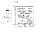
- Fig. 5 is a schematic view showing the entirety of an absolute position length measurement type encoder according to Embodiment 2
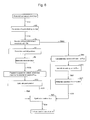
- Fig. 6 is a flowchart showing actions from a space-dividing number conversion circuit to a position data synthesizing circuit
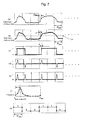
- Fig. 7 is a schematic view showing signals corresponding to respective steps of Fig. 6 .
- the absolute position length measurement type encoder 101 has a configuration similar to the absolute position length measurement type encoder 100 as the entirety according to Embodiment 1. However, the encoder 101 differs from the encoder 100 in that the signal processing circuit 119 includes anedge position detection circuit 128, a peak position detection circuit 130, and a decoding circuit 132 in the front stage of a correlation circuit 134, and includes a position data synthesizing circuit 136 in the back stage of the correlation circuit 134.
- Fig. 5 that shows Embodiment 2
- the same reference numerals are given to the same components as those of Embodiment 1 shown in Fig. 1 .
- a description thereof is omitted, and the description of Embodiment 1 is quoted.
- a detailed description is given of the edge position detection circuit 128, the peak position detection circuit 130, the decoding circuit 132, the correlation circuit 134 and the position data synthesizing circuit 136.
- the edge position detection circuit 128 first binarizes a signal SA4 output from the space-dividing number conversion circuit 124, and when carrying out binarization, it is necessary to provide a predetermined threshold value TH.
- a predetermined threshold value TH For example, in the present embodiment, the middle value between the minimum value and the maximum value of signal SA4 may be used as the predetermined threshold value TH.
- Another predetermined threshold value TH may be obtained based on a histogram or a threshold value TH may be obtained for each of the zones with the zones classified.
- the binarized value is output as signal SA51.
- the binarized value is made into an absolute value after being differentiated. The value is output as signal SA52.
- the peak position detection circuit 130 prepares a histogram in regard to the position that becomes a local maximum value (the maximum value in the minimum line width P ABS ) of a value obtained from signal SA52 for each of the minimum line width P ABS of the ABS pattern 104, and obtains the peak position PK from the histogram.
- the obtained value is output as signal SA6.
- the decoding circuit 132 carries out processing based on a binarized value of the signal SA51 as the peak position PK of the signal SA6 as the position (reference position) where the pseudorandom code to be decoded is changed over as shown in FIG. 5 .
- the decoding circuit 132 decodes the code to the pseudorandom code of 0 or 1 by the unit of the minimum line width P ABS of the ABS pattern 104 from the position shifted only by the peak position PK.
- the decoded code is output as the ABS decoding signal SA7.
- the correlation circuit 134 processes the ABS decoding signal SA7 output from the decoding circuit 132.
- the correlation circuit 134 carries out an arithmetic operation for correlation between the ABS decoding signal SA7 (a digital value subj ected to output of the space-dividing number conversion circuit 124) being a binary value by the unit of the input maximum line width P ABS and a design value of the pseudorandom code used to form the ABS pattern 104.
- the correlation circuit 134 calculates the absolute position of the scale 102 with respect to the light-receiving element 112 and outputs a before-ABS-correction position signal SA8.
- the position data synthesizing circuit 136 obtains an accurate absolute position by shifting the before-ABS-correction position signal SA8 output from the ABS position detection circuit (position detection circuit) 130 only by the peak position PK at the peak position signal SA6 obtained in the peak position detection circuit 130 the and correcting the same.
- the obtained absolute position is output as the ABS synthesization position signal SA9.
- FIG. 7 a description is given of a signal processing flow from the space-dividing number conversion circuit 124 to the position data synthesizing circuit 136 based on FIG. 6 .
- the signal SA3 (Refer to Fig. 7 (A)) digitalized by the A/D conversion circuit 122 is input into the space-dividing number conversion circuit 124, the maximum real number value D is obtained, which satisfies the expressions (1) and (2) with respect to the minimum line width P ABS of the ABS pattern 104 and the array interval P PDA of the ABS light-receiving element array 114.
- the signal SA4 being a digital value for each of the intervals D is obtained based on, for example, the expression (4), and a space-dividing number conversion is carried out (Step 2).
- the signal is output as the signal SA4 in a pattern of Fig. 7(B) .
- the signal SA4 becomes a digital value sampled at a newly obtained interval D.
- the signal SA4 output from the space-dividing number conversion circuit 124 is binarized using a predetermined threshold value TH in the edge position detection circuit 128 (Step S4). And, a binarized and output signal SA51 is brought into a pattern shown in FIG. 7 (C) .
- the binarized value is differentiated in the same edge position detection circuit 128, wherein a rise position and a fall position are detected (Step S6).
- the signal at this time is brought into a pattern shown in FIG. 7(D) .
- the obtained differential signal is made into an absolute value in the same edge position detection circuit 128 (Step S8).
- the signal at this time is brought into a pattern shown in FIG. 7(E) .
- the value at this time is the signal SA52.
- Step S10 With respect to positions where the value made into an absolute value per minimum line width P ABS of the ABS pattern 104 is locally maximized (the maximum value by the unit of the minimum line width P ABS ), a histogram is prepared at a zone of the minimum line width P ABS of the ABS pattern 104 in the peak position detection circuit 126 (Step S10).
- FIG. 7 (F) shows a histogram with respect to the positions where the value is locally maximized in a zone of the minimum line width P ABS of the ABS pattern 104.
- the position where the frequency is maximized is the peak position PK.
- a probability distribution function for example, Gaussian distribution function
- respective values of the histogram are interpolated, and the peak position PK is obtained.
- other probability distribution functions may be adopted, or fitting of not only the probability distribution function but also interpolation between adjacent two points and multiple-order functions may be carried out.
- a position of high frequency may be simply used as the peak position PK as it is.
- the obtained peak position PK is output to the decoding circuit 132 and the position data synthesizing circuit 136 as the peak position signal SA6.
- the numbers of 1 and 0 are added up in the minimum line width P ABS of the respective ABS pattern 104 for every zone of the minimum line width P ABS from the position where shifted only by the peak position PK of the peak position signal SA6, and the total numbers thereof are obtained (Step S14).
- the same decoding circuit 132 compares whether the total number of 1 is greater or the total number of 0 is greater by the unit of the minimum line width P ABS of the ABS pattern 104, and determines the code based on the value of the total number of which is greater. Based on the determined code, the code is decoded (Step S16).
- the ABS decoding signal SA7 output decoded and output from the decoding circuit 132 is brought into a pattern shown in FIG. 7(G) .
- the correlation circuit 134 carries out an arithmetic operation for correlation between the decoded pseudorandom code of the ABS decoding signal SA7 and the design value of the pseudorandom code, and obtains the absolute position of the scale 102 with respect to the light-receiving element 112 (Step S18).
- the value is output as the before-ABS-correction position signal SA8.
- position data are synthesized by adding the peak position PK of the peak position signal SA6 to the absolute position of the before-ABS-correction position signal SA8 in the position data synthesizing circuit 136 (Step S20) .
- the synthesized value is output to the absolute position output circuit 144 as the ABS position data signal SA9.
- the arithmetic operation for correlation is not executed based on the bit number of the A/D converted digital value but is executed by the correlation circuit 134 after binarization and decoding to a code. That is, the digital value subjected to output of the space-dividing number conversion circuit 124 is a value binarized by the unit of the minimum line width P ABS of the ABS pattern 104, and an arithmetic operation for correlation is carried out with the value and the pseudorandom code of the design value, wherein the arithmetic operation amount can be remarkably decreased.
- the arithmetic operation for correlation has conventionally been carried out using a 4-bit digital value by the unit of the array internal P PDA of the ABS light-receiving element array 114, in the present embodiment, it is possible to carry out the arithmetic operation for correlation at a remarkably small amount of data, which is based on only 1-bit, by the unit of the minimum line width P ABS of the ABS pattern 104. That is, even if the absolute position is frequently measured using the ABS pattern 104, stabilized measurement having favorable slaved tracking is enabled for the moving distance.
- the decoding is carried out by the unit of the minimum line width P ABS of the ABS pattern 104, which is the same as the minimum unit of the pseudorandom code of the design value. Therefore, since the lengths of mutual codes are matched with each other when the arithmetic operation for correlation is carried out, it is possible to remarkably clearly determine whether or not there is any correlation. And, since the absolute position is corrected by the peak position PK, highly accurate measurement of the absolute position is enabled.
- the absolute position can be calculated at high accuracy with a small arithmetic operation amount even if the pseudorandom code is used for the ABS pattern 104. Therefore, the absolute position can be frequently calculated from the ABS pattern 104, wherein, for example, if the scale 102 quickly moves greatly, measurement of the moving distance of the scale with respect to the light-receiving element 112 can be carried out with a good slaved tracking performance and the accuracy kept.
- the present invention is not limited thereto.
- a lens array in which a plurality of minor lenses 109A through 109E are juxtaposed in the lens 109 is used.
- images 111 of bright and dark patterns are left-right reversed on the ABS light-receiving element array 115, it is necessary that the reading direction of image data is reversed to the moving direction for each of the minor array 115A through 115E of the ABS light-receiving element array 115.
- the ABS pattern 104 and the ABS light-receiving element array 115 may be disposed in proximity to each other, the absolute position length measurement type encoder itself can be thinned, and can be made durable against disturbance.
- the absolute position was obtained by carrying out an arithmetic operation for correlation using the correlation circuits 126 and 134
- the present invention is not limited thereto.
- a circuit for obtaining an absolute position by referencing a table may be provided instead of the correlation circuits 126 and 134.
- the digital values subjected to output of the space-dividing number conversion circuit are regarded as address signals, and reference is made to memories shown by the respective address signals.
- absolute positions corresponding to the respective address signals are stored in the respective memories in advance, whereby it becomes possible to obtain the absolute positions from the address signals.
- it is difficult to obtain accurate absolute positions if an error occurs in the address signals it is possible to obtain absolute positions at a high speed since no complicated arithmetic operations are carried out.
- the bright and dark patterns formed by the scale 102 are formed by transmission light of the scale 102, for example, the present invention is not limited thereto.
- the present invention is not limited thereto.
- such a configuration may be adopted, in which bright and dark patterns are formed by the projection light R0 to the scale 102A being reflected, and are imaged on the light-receiving element 112.
- decoding is carried out in such a manner that the total numbers of 1 and 0 are obtained at a cycle of the minimum line width P ABS , comparison is carried out with respect to whether the total number of 1 is greater or the total number of 0 is greater, and the code is determined by the value the total number of which is greater.
- the code of the minimum line width P ABS may be determined and decoded by determining that the value at a specified position (for example, the center) of the cycle of the minimum line width P ABS is 1 or 0.
- the interval D is the maximum real number value D that satisfies the expressions (1) and (2)
- the present invention is not limited thereto. It is sufficient that the interval D is smaller than the array internal P PDA . If so, since the correlation can be obtained by the resolution power of the interval D when carrying out an arithmetic operation for correlation, the absolute positions can be measured further minutely than the array interval P PDA , and the total amount of calculation can be further decreased, wherein the absolute positions can be measured at a further higher speed.
Landscapes
- Physics & Mathematics (AREA)
- General Physics & Mathematics (AREA)
- Engineering & Computer Science (AREA)
- Signal Processing (AREA)
- Optical Transform (AREA)
Abstract
Description
- The present invention relates to an absolute position length measurement type encoder that includes a scale in which an ABS pattern based on a pseudorandom code is provided, a light-receiving element for receiving bright and dark patterns formed by the scale, and a signal processing circuit for processing signals in compliance with output of the light-receiving element and measuring an absolute position of the scale with respect to the light-receiving element, and in particular to an absolute position length measurement type encoder capable of measuring a moving distance at high accuracy by arithmetic operations for correlation without being influenced by an array interval of ABS light-receiving element array of the light-receiving element.
- Accurate position control and measurement are indispensable in measuring instruments and apparatuses. Therefore, an absolute position length measurement type encoder capable of executing absolute position measurement over some length has been used. In particular, where high accuracy is required, a photoelectric type encoder has been used.
- Generally, an absolute position length measurement type photoelectric encoder has an absolute pattern (hereinafter called anABS pattern) to roughly measure a moving distance and an incremental pattern (hereinafter called an INC pattern) to measure a moving distance at high resolution power by interpolating the interval of a roughly obtained moving distance on a scale. The light-receiving element includes ABS light-receiving element array for ABS pattern and INC light-receiving element array for INC pattern.
- Since bright and dark patterns formed by ABS pattern and INC pattern, which are formed on the scale, change on the light-receiving element, which receives the bright and dark patterns, the moving distance can be measured at high accuracy by processing the change in a signal processing circuit. The ABS pattern is prepared based on a pseudorandom code, and patterns to be used can be made into one,
wherein the absolute position length measurement type encoder itself can be downsized. Also, since highly accurate measurement is enabled for a moving distance in measurement of the absolute position, a method for arithmetic operation for correlation has been used (For example, Japanese Published Unexamined Patent Application No.2002-230560 2006-226987 - However, digital signals used for arithmetic operations for correlation are discrete data obtained per array interval of the ABS light-receiving element array. Therefore, when carrying out an arithmetic operation for correlation using the discrete data, it was assumed that an integral multiple of the array interval of the ABS light-receiving element array is equal to the minimum line width of the ABS pattern based on the pseudorandom code being an object of the arithmetic operation for correlation (
Patent Documents 1 and 2). However, there is a restriction in the array interval of the ABS light-receiving element array, freedom for selection of the light-receiving elements was necessarily reduced. Also, the degree of freedom in design for the minimum line width of the ABS pattern could not be sufficiently secured. As a result, there is a problem in that adverse influences are given to the size and performance of the absolute position length measurement type encoder and to the production cost thereof. - The present invention was developed to solve the above-described problems of the prior arts, and it is therefore an object to provide an absolute position length measurement type encoder capable of carrying out arithmetic operations for correlation even where the minimum line width of ABS pattern is not an integral multiple of the array interval of ABS light-receiving element array and measuring a moving distance at high accuracy.
- A first aspect of the present invention is an absolute position length measurement type encoder including:
- a scale in which an ABS pattern based on a pseudorandom code is provided;
- a light-receiving element for receiving bright and dark patterns formed by the scale; and
- a signal processing circuit for processing signals subjected to output of the light-receiving element and measuring an absolute position of the scale to the light-receiving element;
- A second aspect of the present invention is featured in that the array interval PPDA of the ABS light-receiving element array is made into one-third or less the minimum line width PABS of the ABS pattern.
- A third aspect of the present invention is featured in that the signal processing circuit further includes a correlation circuit for executing arithmetic operations for correlation between a digital value subjected to output of the space-dividing number conversion circuit and a design value of the pseudorandom code.
- A fourth aspect of the present invention is featured in that the interval D is made into the maximum real number value, which satisfies expressions (1) and (2) with respect to the array interval PPDA and the minimum line width PABS of the ABS pattern.


- A fifth aspect of the present invention is featured in that the digital values for each of the intervals D are obtained by linearly interpolating two digital values adjacent to each other in digital values subjected to output of the ABS light-receiving element array.
- A sixth aspect of the present invention is featured in that the scale is provided with an INC pattern.
- A seventh aspect of the present invention is featured in further including:
- a light-receiving element for receiving bright and dark patterns formed by the INC pattern;
- an incremental position detection circuit for detecting an incremental position by processing signals output from the light-receiving element; and
- an absolute position outputting circuit for selecting which one of a signal output from the incremental position detection circuit and an ABS position signal output from a correlation circuit in the signal processing circuit is to be output as a position data signal.
- An eighth aspect of the present invention is featured in that the absolute position outputting circuit normally selects the signal output from the incremental position detection circuit, references the same signal to the ABS position signal once every predetermined time interval, outputs the ABS position signal as the position data signal if there is a difference between the positions obtained from the two signals, feeds the position data signal back to the incremental position detection circuit, and simultaneously sets the same position data signal in the inside of the incremental position detection circuit as the current value.
- A ninth aspect of the present invention is featured in that the feedback is carried out when the data are not renewed at a data refreshing rate in the correlation circuit.
- Also, a tenth aspect of the present invention is featured in that the digital value subj ected to arithmetic operations for correlation by the correlation circuit is made into a value binarized by the unit of the minimum line width PABS of the ABS pattern.
- An eleventh aspect of the present invention is featured in that the signal processing circuit includes; in the front stage of the correlation circuit,
- an edge position detection circuit for first binarizing a signal output from the space-dividing number conversion circuit;
- a peak position detection circuit for preparing a histogram with respect to a position where a value obtained from a signal differentiated and made into an absolute value after being binarized becomes a local maximum value, for each of the minimum line width PABS of the ABS pattern and for obtaining a peak position PK from the histogram; and
- a decoding circuit for processing the peak position PK based on the binarized value of a signal as the position where the pseudorandom code to be decoded is changed over; and includes: in the back stage of the correlation circuit,
- a position data synthesizing circuit for obtaining an accurate absolute position, with respect to the before-ABS-correction position signal output from the correlation circuit, through position correction by shifting the absolute position only by the peak position PK by means of a peak position signal obtained by the peak position detection circuit.
- A twelfth aspect of the present invention is featured in that the peak position detection circuit obtains the peak position PK by interpolating respective values of the histogram by fitting a probability distribution function by the least-squares method.
- A thirteenth aspect of the present invention is featured in that the decoding circuit obtains respective total sums of the binarized values in the minimum line width PABS, determines and decodes the code of the minimum line width PABS with a value having a greater total sum.
- A fourteenth aspect of the present invention is featured in that the correlation circuit carries out arithmetic operations for correlation between the decoded pseudorandom code and the design value of the pseudorandom code, and obtains the absolute position of the scale with respect to the light-receiving element.
- A fifteenth aspect of the present invention is featured in that the position data synthesizing circuit synthesizes position data by adding the peak position PK of the peak position signal to the absolute position of the absolute position signal.
- According to the present invention, where the minimum line width PABS of the ABS pattern is not an integral multiple of the array interval PPDA of the ABS light-receiving element array, a finer interval than the array interval PPDA may be made into a minimum resolution power, wherein the moving distance can be measured without lowering the accuracy. Therefore, the degree of freedom in design of the minimum line width of the ABS pattern and range of selection of the light-receiving element can be widened, wherein it becomes possible to compose an absolute position length measurement type encoder having a greater degree of freedom with respect to the size, performance and cost thereof.
- Also, an absolute position length measurement type encoder can be composed, which, where an arithmetic operation for correlation is carried out, is robust and capable of correctly measuring the moving distance even if there is an error in output of the ABS light-receiving element array.
- In particular, where the interval D is the maximum real number value that satisfies the expressions (1) and (2), it becomes possible to quickly measure the moving distance at a further higher accuracy without increasing the arithmetic operation amount more than necessary.
- These and other novel features and advantages of the present invention will become apparent from the following detailed description of preferred embodiments.
- The preferred embodiments will be described with reference to the drawings, wherein like elements have been denoted throughout the figures with like reference numerals, and wherein;
-
Fig. 1 is a schematic view showing the entirety of an absolute position length measurement type encoder according toEmbodiment 1 of the present invention; -
Fig. 2 is a perspective view schematically showing the relationship between a light-emitting element, a scale and a light-receiving element according thereto; -
Fig. 3 is a schematic view showing the scale according thereto; -
Fig. 4 is a schematic view showing the light-receiving element according thereto; -
Fig. 5 is a schematic view showing the entirety of an absolute position length measurement type encoder according to Embodiment 2 of the present invention; -
Fig. 6 is a flowchart showing actions from a space-dividing number conversion circuit to a position data synthesizing circuit according thereto; -
Fig. 7 is a schematic view showing signals corresponding to respective steps ofFig. 6 according thereto; -
Fig. 8 is a schematic view exemplarily showing the relationship between an ABS pattern, a lens array and a light-receiving element according to Embodiment 3 of the present invention; and -
Fig. 9 is a schematic view exemplarily showing the relationship between a light-emitting element, a scale and a light-receiving element according toEmbodiment 4 of the present invention. - Hereinafter, a detailed description is given of embodiments of the present invention with reference to the drawings.
-
Embodiment 1 according to the present invention will be described usingFig. 1 through Fig. 4 .Fig. 1 is a schematic view showing the entirety of an absolute position length measurement type encoder according toEmbodiment 1 of the present invention,Fig. 2 is a perspective view schematically showing the relationship between a light-emitting element, a scale and a light-receiving element, andFig. 3 is a schematic view showing the scale,Fig. 4 is a schematic view of a light-receiving element. - First, a brief description is given of the entire configuration of the present embodiment.
- Mainly as shown in
Fig. 1 , an absolute position lengthmeasurement type encoder 100 includes - a scale 102 (Refer to
Figs. 2 and3 ) in which anABS pattern 104 based on a pseudorandom code is provided, - a light-receiving
element 112 for receiving bright and dark patterns formed by thescale 102 and - a
signal processing circuit 118 for processing signals subjected to output of the light-receivingelement 112 and for measuring the absolute position of thescale 102 with respect to the light-receivingelement 112. - Here, the
signal processing circuit 118 includes - a space-dividing
number conversion circuit 124 for obtaining a finer interval D than the array interval PPDA of the ABS light-receivingelement array 114 of the light-receivingelement 112 and obtaining and outputting a digital value for each of the intervals D in compliance with output of the ABS light-receivingelement array 114; and - a
correlation circuit 126 for carrying out arithmetic operations for correlation between a digital value subjected to output of the space-dividingnumber conversion circuit 124 and the design value of a pseudorandom code. - A detailed description is given below of respective components.
- As shown in
FIG. 2 andFIG. 3 , thescale 102 includes theABS pattern 104 and theINC pattern 106. As shown inFIG. 2 , as light R0 projected from the light-emittingelement 108 is irradiated onto thescale 102 orthogonal to the optical axis direction (Y-axis direction), bright and dark patterns are imaged on the light-receivingelement 112 via thelens 110 by means of theABS pattern 104 and theINC pattern 106. TheABS pattern 104 and theINC pattern 106 can form bright and dark patterns by being brought into a transparent state where the projection light R0 is not interrupted, if the code is 1, and into a non-transparent state where the projection light R0 is interrupted, if the code is 0, for example. - A pseudorandom code is used for the
ABS pattern 104. Here, for example, M-sequence code, which becomes the longest cycle, of the code series generated by a shift register may be used as the pseudorandom code. At this time, the line width per one pseudorandom code becomes the minimum line width PABS of theABS pattern 104 as shown inFIG. 3 . TheINC pattern 106 is a pattern consisting of cyclically formed 1 and 0. In the present embodiment, theABS pattern 104 is disposed upside in the Z-axis direction inFIG. 3 while theINC pattern 106 is disposed downside. For example, an LED may be used as the light-emittingelement 108. - The
lens 110 may be composed of a single lens (for example, cylindrical lens, etc.) by which twopatterns FIG. 2 . Or, thelens 110 may be composed of two lenses, by which theABS pattern 104 and theINC pattern 106 are individually imaged. In addition, thelens 110 may not necessarily be used. - As shown in
FIG. 4 , the light-receivingelement 112 includes two light-receivingelement arrays element array 114, and the other of which is a light-receivingelement array 116 for the INC pattern (hereinafter referred to as an INC light-receiving element array). The array arrangement pitch PPDA of the ABS light-receivingelement array 114 is as shown inFIG. 4 . That is, the spatial resolution power of the ABS light-receivingelement array 114 becomes an array arrangement pitch PPDA. Here, the array arrangement pitch PPDA is narrower than the minimum line width PABS of theABS pattern 104, and may be made into, for example, one-third thereof or less. If the array arrangement pitch PPDA is made still narrower, the number of samplings in the minimum line width PABS is increased, and further highly accurate measurement of the absolute position can be carried out. The ABS light-receivingelement array 114 outputs an ABS bright and dark signal SA1 by sweeping the bright and dark patterns formed by theABS pattern 104 in the array direction (the X-axis direction) . - The INC light-receiving
element array 116 has a four-phase output with a phase difference of 90° (not illustrated). The INC light-receivingelement array 116 sweeps the bright and dark patterns formed by theINC pattern 106 in the array direction (the X-axis direction), and outputs the INC bright and dark signal SI1. Where the bright and dark patterns formed by theINC pattern 106 are detected by the INC light-receivingelement array 116 consisting of four phases with a phase difference of 90°, a four-phase sinusoidal wave signal with a phase difference of 90° is output. In addition, the array arrangement pitch of the INC light-receivingelement array 116 is narrower than the array arrangement pitch PPDA of the ABS light-receivingelement array 114 in order to interpolate between an obtained absolute position and the absolute position. - As showninFIG. 1, anoise filter/amplificationcircuit 120 processes the ABS bright and dark signal SA1 output from the light-receiving
element 112. At this time, the noise filter/amplification circuit 120 cuts off high frequency noise by its low-pass filter, carries out amplification at a predetermined gain, and outputs a signal SA2. - As shown in
FIG. 1 , an A/D conversion circuit 122 converts the signal SA2 output from the noise filter/amplification circuit 120 from analog signals to digital signals, and outputs a signal SA3. - As shown in
Fig. 1 , the space-dividingnumber conversion circuit 124 matches the intervals between a signal SA3 of the array interval PPDA output from the A/D conversion circuit 122 and the design value of the ABS pattern based on the pseudorandom code, in order to clearly distinguish the correlation, when an arithmetic operation for correlation is carried out between both data in acorrelation circuit 126. In detail, based on a thought similar to the greatest common divisor of an integral number in elementary mathematics, the maximum real number value D that satisfies the expressions (1) and (2) at the same time is obtained as the interval D. -


- That is, since k1 is greater than 1, the interval D is made finer than the array interval PPDA.
- As a detailed example, when the minimum line width PABS of the
ABS pattern 104 is 50µm, and the array interval PPDA of the ABS light-receivingelement array 114 is 3.5µm, the interval D becomes 0.5µm. - Also, although not corresponding to the present invention, where k1=1, since the array interval PPDA is made equal to the interval D, the expression (2) may be expressed by the expression (3) below.

- That is, when the minimum line width PABS becomes an integral multiple of the array interval PPDA, the expressions (1) and (2) may be used. Therefore, even when the minimum line width PABS becomes an integral multiple of the array interval PPDA, no disadvantage is brought about if the space-dividing
number conversion circuit 124 is used. - If the interval D is obtained by the expressions (1) and (2), the space-dividing
number conversion circuit 124 newly obtains a digital value for each of the intervals D from the digital value (Signal SA3) subjected to output of the ABS light-receivingelement array 114. In its most simplistic form, for example, digital values F (PPDA*x+D*i) for each of the intervals D can be obtained by linearly interpolating two digital values (Signal SA3) adj acent to each other. At this time, the following expression (4) may be used.
- Here, i is an integral number (0<i<k1), F(PPDA*x) and F(PPDA*(x+1)) respectively show digital values obtained at the xth time and at the (x+1)th time of the array interval PPDA. Also, a digital value F for each of the intervals D may be obtained by partially approximating by a high-order function. For example, by applying a three-order polynomial expression to digital values (Signal SA3) at four points adjacent to each other, the interval between the second point and the third point, which becomes just the middle, is interpolated, whereby the digital value F for each of the intervals D may be obtained.
- The digital value F of the interval D thus obtained is output as a signal SA4.
- As shown in
Fig. 1 , thecorrelation circuit 126 processes the signal SA4 output from the space-dividingnumber conversion circuit 124. In detail, an arithmetic operation for correlation is carried out between the digitalized signal SA4 (the digital value subjected to output of the space-dividing number conversion circuit 124) of the interval D and the design value of the pseudorandom code used to form theABS pattern 104, and calculates the absolute position of thescale 102 with respect to the light-receivingelement 112 and outputs the ABS position signal SA9. - The noise filter/
amplification circuit 140 processes a four-phase sinusoidal wave signal with a phase difference of 90°, which is an INC bright and dark signal SI1, as shown inFIG. 1 . In detail, the noise filter/amplification circuit 140 cuts off high frequency noise by its low pass filter with respect to the INC bright and dark signal SI1, carries out amplification at a predetermined gain, and outputs a signal SI2. - The INC
position detection circuit 142 processes the signal SI2 output from the noise filter/amplification circuit 140 as shown inFIG. 1 . In detail, the INCposition detection circuit 142 generates a two-phase sinusoidal wave signal with a phase difference of 90° from the four-phase sinusoidal wave signal with a phase difference of 90°, carries out an arc tangent operation, obtains the relative position and outputs the result as a signal SI3. - The absolute
position output circuit 144 selects, as shown inFIG. 1 , which of the signal SI3 output from the INCposition detection circuit 142 or the ABS position signal SA9 output from thecorrelation circuit 126 is output as a position data signal Sout. In the present embodiment, for example, usually the signal SI3 is selected, and the ABS position signal SA9 is output as the position data signal Sout if there is a difference in the positions obtained from two signals by referencing the signal SI3 to the ABS position signal SA9 once every predetermined interval of time (which is appropriately set by the use conditions). Along therewith, the position data signal Sout is fed back to the INCposition detection circuit 142 and is set as the current value inside the INCposition detection circuit 142. In addition, the feedback is carried out when data are not renewed by a data refreshing rate in thecorrelation circuit 126. - Thus, even where the minimum line width PABS of the
ABS pattern 104 is not an integral multiple of the array interval PPDA of the light-receivingelement array 114, the interval D, which is finer than the array interval PPDA, may be made into the minimum resolution power. Therefore, since it is possible to obtain the absolute position at least further finer than the resolution power of the array interval PPDA, the moving distance can be measured without lowering the accuracy. Accordingly, the degree of freedom in design of the minimum line width PABS of theABS pattern 104 and the range of selection of the light-receivingelement 112 can be widened, wherein it becomes possible to compose an absolute position lengthmeasurement type encoder 100 having a higher degree of freedom with respect to the size, performance, and production costs thereof. - Also, the absolute position is obtained by carrying out an arithmetic operation for correlation in the
correlation circuit 126. That is, since the absolute position is obtained with the highest correlation value, it is possible to correctly measure the moving distance even if there is some margin for error in output of the ABS light-receivingelement array 114. That is, even if thescale 102 is subjected to damage and/or foreign substances and the bright and dark patterns based on theABS pattern 104 are thereby influenced, it is possible to compose a robust absolute position lengthmeasurement type encoder 100 capable of securing the measurement accuracy. - In particular, in the present embodiment, since the interval D is the maximum real number value that satisfies the expressions (1) and (2), it becomes possible to quickly measure the moving distance at a further higher accuracy without increasing the arithmetic operation amount more than necessary.
- Next, a description is given of Embodiment 2 according to the present invention with reference to
Fig. 5 through Fig. 7 . -
Fig. 5 is a schematic view showing the entirety of an absolute position length measurement type encoder according to Embodiment 2,Fig. 6 is a flowchart showing actions from a space-dividing number conversion circuit to a position data synthesizing circuit, andFig. 7 is a schematic view showing signals corresponding to respective steps ofFig. 6 . - As shown in
Fig. 5 , the absolute position lengthmeasurement type encoder 101 has a configuration similar to the absolute position lengthmeasurement type encoder 100 as the entirety according toEmbodiment 1. However, theencoder 101 differs from theencoder 100 in that thesignal processing circuit 119 includes anedgeposition detection circuit 128, a peakposition detection circuit 130, and adecoding circuit 132 in the front stage of acorrelation circuit 134, and includes a positiondata synthesizing circuit 136 in the back stage of thecorrelation circuit 134. - Therefore, in
Fig. 5 that shows Embodiment 2, the same reference numerals are given to the same components as those ofEmbodiment 1 shown inFig. 1 . A description thereof is omitted, and the description ofEmbodiment 1 is quoted. In the present embodiment, a detailed description is given of the edgeposition detection circuit 128, the peakposition detection circuit 130, thedecoding circuit 132, thecorrelation circuit 134 and the positiondata synthesizing circuit 136. - As shown in
FIG. 5 , the edgeposition detection circuit 128 first binarizes a signal SA4 output from the space-dividingnumber conversion circuit 124, and when carrying out binarization, it is necessary to provide a predetermined threshold value TH. For example, in the present embodiment, the middle value between the minimum value and the maximum value of signal SA4 may be used as the predetermined threshold value TH. Another predetermined threshold value TH may be obtained based on a histogram or a threshold value TH may be obtained for each of the zones with the zones classified.
And, the binarized value is output as signal SA51. The binarized value is made into an absolute value after being differentiated. The value is output as signal SA52. - As shown in
FIG. 5 , the peakposition detection circuit 130 prepares a histogram in regard to the position that becomes a local maximum value (the maximum value in the minimum line width PABS) of a value obtained from signal SA52 for each of the minimum line width PABS of theABS pattern 104, and obtains the peak position PK from the histogram. The obtained value is output as signal SA6. - The
decoding circuit 132 carries out processing based on a binarized value of the signal SA51 as the peak position PK of the signal SA6 as the position (reference position) where the pseudorandom code to be decoded is changed over as shown inFIG. 5 . In detail, thedecoding circuit 132 decodes the code to the pseudorandom code of 0 or 1 by the unit of the minimum line width PABS of theABS pattern 104 from the position shifted only by the peak position PK. The decoded code is output as the ABS decoding signal SA7. - As shown in
Fig. 5 , thecorrelation circuit 134 processes the ABS decoding signal SA7 output from thedecoding circuit 132. In detail, thecorrelation circuit 134 carries out an arithmetic operation for correlation between the ABS decoding signal SA7 (a digital value subj ected to output of the space-dividing number conversion circuit 124) being a binary value by the unit of the input maximum line width PABS and a design value of the pseudorandom code used to form theABS pattern 104. And, thecorrelation circuit 134 calculates the absolute position of thescale 102 with respect to the light-receivingelement 112 and outputs a before-ABS-correction position signal SA8. - As shown in
FIG. 5 , the positiondata synthesizing circuit 136 obtains an accurate absolute position by shifting the before-ABS-correction position signal SA8 output from the ABS position detection circuit (position detection circuit) 130 only by the peak position PK at the peak position signal SA6 obtained in the peakposition detection circuit 130 the and correcting the same. The obtained absolute position is output as the ABS synthesization position signal SA9. - Next, referring to
FIG. 7 , a description is given of a signal processing flow from the space-dividingnumber conversion circuit 124 to the positiondata synthesizing circuit 136 based onFIG. 6 . - First, when the signal SA3 (Refer to
Fig. 7 (A)) digitalized by the A/D conversion circuit 122 is input into the space-dividingnumber conversion circuit 124, the maximum real number value D is obtained, which satisfies the expressions (1) and (2) with respect to the minimum line width PABS of theABS pattern 104 and the array interval PPDA of the ABS light-receivingelement array 114. And, the signal SA4 being a digital value for each of the intervals D is obtained based on, for example, the expression (4), and a space-dividing number conversion is carried out (Step 2). As a result, the signal is output as the signal SA4 in a pattern ofFig. 7(B) . As shown inFig. 7(B) , the signal SA4 becomes a digital value sampled at a newly obtained interval D. - Next, the signal SA4 output from the space-dividing
number conversion circuit 124 is binarized using a predetermined threshold value TH in the edge position detection circuit 128 (Step S4). And, a binarized and output signal SA51 is brought into a pattern shown inFIG. 7 (C) . - Next, the binarized value is differentiated in the same edge
position detection circuit 128, wherein a rise position and a fall position are detected (Step S6). The signal at this time is brought into a pattern shown inFIG. 7(D) . - Next, the obtained differential signal is made into an absolute value in the same edge position detection circuit 128 (Step S8). The signal at this time is brought into a pattern shown in
FIG. 7(E) . The value at this time is the signal SA52. - Next, with respect to positions where the value made into an absolute value per minimum line width PABS of the
ABS pattern 104 is locally maximized (the maximum value by the unit of the minimum line width PABS), a histogram is prepared at a zone of the minimum line width PABS of theABS pattern 104 in the peak position detection circuit 126 (Step S10). - Next, the peak position PK for frequency in the histogram is calculated in the same peak position detection circuit 130 (Step S12).
FIG. 7 (F) shows a histogram with respect to the positions where the value is locally maximized in a zone of the minimum line width PABS of theABS pattern 104. In the drawing, the position where the frequency is maximized is the peak position PK. In the present embodiment, by fitting a probability distribution function (for example, Gaussian distribution function) by the least-squares method, respective values of the histogram are interpolated, and the peak position PK is obtained. Also, other probability distribution functions may be adopted, or fitting of not only the probability distribution function but also interpolation between adjacent two points and multiple-order functions may be carried out. Further, a position of high frequency may be simply used as the peak position PK as it is. The obtained peak position PK is output to thedecoding circuit 132 and the positiondata synthesizing circuit 136 as the peak position signal SA6. - Next, in the
decoding circuit 132, the numbers of 1 and 0 are added up in the minimum line width PABS of therespective ABS pattern 104 for every zone of the minimum line width PABS from the position where shifted only by the peak position PK of the peak position signal SA6, and the total numbers thereof are obtained (Step S14). - Next, with respect to the added-up result, the
same decoding circuit 132 compares whether the total number of 1 is greater or the total number of 0 is greater by the unit of the minimum line width PABS of theABS pattern 104, and determines the code based on the value of the total number of which is greater. Based on the determined code, the code is decoded (Step S16). The ABS decoding signal SA7 output decoded and output from thedecoding circuit 132 is brought into a pattern shown inFIG. 7(G) . - Next, the
correlation circuit 134 carries out an arithmetic operation for correlation between the decoded pseudorandom code of the ABS decoding signal SA7 and the design value of the pseudorandom code, and obtains the absolute position of thescale 102 with respect to the light-receiving element 112 (Step S18). The value is output as the before-ABS-correction position signal SA8. - Next, position data are synthesized by adding the peak position PK of the peak position signal SA6 to the absolute position of the before-ABS-correction position signal SA8 in the position data synthesizing circuit 136 (Step S20) . The synthesized value is output to the absolute
position output circuit 144 as the ABS position data signal SA9. - Thus, in the present embodiment, in addition to the effects obtained in
Embodiment 1, the arithmetic operation for correlation is not executed based on the bit number of the A/D converted digital value but is executed by thecorrelation circuit 134 after binarization and decoding to a code. That is, the digital value subjected to output of the space-dividingnumber conversion circuit 124 is a value binarized by the unit of the minimum line width PABS of theABS pattern 104, and an arithmetic operation for correlation is carried out with the value and the pseudorandom code of the design value, wherein the arithmetic operation amount can be remarkably decreased. For example, if it is assumed that the arithmetic operation for correlation has conventionally been carried out using a 4-bit digital value by the unit of the array internal PPDA of the ABS light-receivingelement array 114, in the present embodiment, it is possible to carry out the arithmetic operation for correlation at a remarkably small amount of data, which is based on only 1-bit, by the unit of the minimum line width PABS of theABS pattern 104. That is, even if the absolute position is frequently measured using theABS pattern 104, stabilized measurement having favorable slaved tracking is enabled for the moving distance. - Simultaneously, the decoding is carried out by the unit of the minimum line width PABS of the
ABS pattern 104, which is the same as the minimum unit of the pseudorandom code of the design value. Therefore, since the lengths of mutual codes are matched with each other when the arithmetic operation for correlation is carried out, it is possible to remarkably clearly determine whether or not there is any correlation. And, since the absolute position is corrected by the peak position PK, highly accurate measurement of the absolute position is enabled. - That is, in the present embodiment, the absolute position can be calculated at high accuracy with a small arithmetic operation amount even if the pseudorandom code is used for the
ABS pattern 104. Therefore, the absolute position can be frequently calculated from theABS pattern 104, wherein, for example, if thescale 102 quickly moves greatly, measurement of the moving distance of the scale with respect to the light-receivingelement 112 can be carried out with a good slaved tracking performance and the accuracy kept. - The present invention has been described based on
Embodiments 1 and 2 described above. However, the present invention is not limited to the above-described embodiments. That is, it is a matter of course that the present invention may be subjected to various modifications and variations in design within the scope not departing from the gist of the present invention. - In the above-described embodiments, it was configured that bright and dark patterns are imaged all in the X-axis direction of the ABS light-receiving
element array 114 by asingle lens 110. However, the present invention is not limited thereto. For example, as in Embodiment 3 shown inFig. 8 , it may be possible that a lens array in which a plurality ofminor lenses 109A through 109E are juxtaposed in thelens 109 is used. In this case, sinceimages 111 of bright and dark patterns are left-right reversed on the ABS light-receivingelement array 115, it is necessary that the reading direction of image data is reversed to the moving direction for each of theminor array 115A through 115E of the ABS light-receivingelement array 115. However, since theABS pattern 104 and the ABS light-receivingelement array 115 may be disposed in proximity to each other, the absolute position length measurement type encoder itself can be thinned, and can be made durable against disturbance. - Also, in the above-described embodiments, although the absolute position was obtained by carrying out an arithmetic operation for correlation using the
correlation circuits correlation circuits - Further, although, in the embodiments described above, the bright and dark patterns formed by the
scale 102 are formed by transmission light of thescale 102, for example, the present invention is not limited thereto. For example, as inEmbodiment 4 shown inFIG. 9 , such a configuration may be adopted, in which bright and dark patterns are formed by the projection light R0 to thescale 102A being reflected, and are imaged on the light-receivingelement 112. - Also, for example, in the embodiment described above, in order to decode the pseudorandom code from the binarized values, decoding is carried out in such a manner that the total numbers of 1 and 0 are obtained at a cycle of the minimum line width PABS, comparison is carried out with respect to whether the total number of 1 is greater or the total number of 0 is greater, and the code is determined by the value the total number of which is greater. However, the present invention is not limited thereto. For example, the code of the minimum line width PABS may be determined and decoded by determining that the value at a specified position (for example, the center) of the cycle of the minimum line width PABS is 1 or 0.
- In addition, in the above-described embodiments, although the interval D is the maximum real number value D that satisfies the expressions (1) and (2), the present invention is not limited thereto. It is sufficient that the interval D is smaller than the array internal PPDA. If so, since the correlation can be obtained by the resolution power of the interval D when carrying out an arithmetic operation for correlation, the absolute positions can be measured further minutely than the array interval PPDA, and the total amount of calculation can be further decreased, wherein the absolute positions can be measured at a further higher speed.
Claims (15)
- An absolute position length measurement type encoder (100) comprising:a scale (102) in which an ABS pattern (104) based on a pseudorandom code is provided;a light-receiving element (112) for receiving bright and dark patterns formed by the scale; anda signal processing circuit (118) for processing signals subjected to output of the light-receiving element and measuring an absolute position of the scale to the light-receiving element;wherein the signal processing circuit includes a space-dividing number conversion circuit (124) that obtains finer intervals D than the array interval PPDA of the ABS light-receiving element array (114) of the light-receiving element, and simultaneously obtains and outputs a digital value (SA4) for each of the intervals D subjected to output of the ABS light-receiving element array.
- The absolute position length measurement type encoder according to claim 1, wherein the array interval PPDA of the ABS light-receiving element array is made into one-third or less the minimum line width PABS of the ABS pattern.
- The absolute position length measurement type encoder according to claim 1 or claim 2, wherein the signal processing circuit further includes a correlation circuit (126) for executing arithmetic operations for correlation between a digital value subjected to output of the space-dividing number conversion circuit and a design value of the pseudorandom code.
- The absolute position length measurement type encoder according to any of the preceding claims, wherein the interval D is made into the maximum real number value, which satisfies expressions (1) and (2) with respect to the array interval PPDA and the minimum line width PABS of the ABS pattern.


- The absolute position length measurement type encoder according to any of the preceding claims, wherein the digital values for each of the intervals D are obtained by linearly interpolating two digital values adjacent to each other in the digital values (SA3) subjected to output of the ABS light-receiving element array.
- The absolute position length measurement type encoder according to any of the preceding claims, wherein the scale is provided with an INC pattern (106).
- The absolute position length measurement type encoder according to claim 6, further comprising:a light-receiving element (116) for receiving bright and dark patterns formed by the INC pattern;an incremental position detection circuit (142) for detecting an incremental position by processing signals (SI1) output from the light-receiving element; andan absolute position outputting circuit (144) for selecting which one of a signal (SI3) output from the incremental position detection circuit and an ABS position signal (SA9) output from a correlation circuit (126) in the signal processing circuit (118) is to be output as a position data signal (Sout).
- The absolute position length measurement type encoder according to claim 7, wherein the absolute position outputting circuit (144) usually select the signal (SI3) output from the incremental position detection circuit, references the same signal (SI3) to the ABS position signal (SA9) once every predetermined time interval, outputs the ABS position signal (SA9) as the position data signal (Sout) if there is a difference between the positions obtained from the two signals, feeds the position data signal (Sout) back to the incremental position detection circuit (142), and simultaneously sets the same position data signal in the inside of the incremental position detection circuit (142) as the current value.
- The absolute position length measurement type encoder according to claim 8, wherein the feedback is carried out when the data are not renewed at a data refreshing rate in the correlation data circuit (126).
- The absolute position length measurement type encoder according to at least claim 3, wherein the digital value subjected to arithmetic operations for correlation by the correlation circuit is made into a value (SA7) binarized by the unit of the minimum line width PABS of the ABS pattern.
- The absolute position length measurement type encoder according to claim 10, wherein the signal processing circuit comprising; in the front stage of the correlation circuit (134),an edge position detection circuit (128) for first binarizing a signal (SA4) output from the space-dividing number conversion circuit (124);a peak position detection circuit (130) for preparing a histogram with respect to a position where a value obtained from a signal (SA52) differentiated and made into an absolute value after being binarized becomes a local maximum value, for each of the minimum line width PABS of the ABS pattern and for obtaining a peak position PK from the histogram; anda decoding circuit (132) for processing the peak position PK based on the binarized value of a signal as the position where the pseudorandom code to be decoded is changed over; and includes:
in the back stage of the correlation circuit (134),a position data synthesizing circuit (136) for obtaining an accurate absolute position, with respect to a before-ABS-correction position signal (SA8) output from the correlation circuit, through position correction by shifting the absolute position only by the peak position PK by means of a peak position signal (SA6) obtained by the peak position detection circuit (130). - The absolute position length measurement type encoder according to claim11, wherein the peak position detection circuit (126) obtains the peak position PK by interpolating respective values of the histogram by fitting a probability distribution function by the least-squares method.
- The absolute position length measurement type encoder according to claim 11 or claim 12, wherein the decoding circuit (132) obtains respective total number of the binarized values in the minimum line width PABS, determines and decodes the code of the minimum line width PABS with a value having a greater total number.
- The absolute position length measurement type encoder according to any of claims 11 to 13, wherein the correlation circuit (134) carries out arithmetic operations for correlation between the decoded pseudorandom code and the design value of the pseudorandom code, and obtains the absolute position of the scale (102) with respect to the light-receiving element (112).
- The absolute position length measurement type encoder according to any of claims 11 to 14, wherein the position data synthesizing circuit (136) synthesizes position data by adding the peak position PK of the peak position signal (SA6) to the absolute position of the absolute position signal (SA8).
Applications Claiming Priority (1)
| Application Number | Priority Date | Filing Date | Title |
|---|---|---|---|
| JP2008125631A JP5103267B2 (en) | 2008-05-13 | 2008-05-13 | Absolute position measuring encoder |
Publications (2)
| Publication Number | Publication Date |
|---|---|
| EP2120019A2 true EP2120019A2 (en) | 2009-11-18 |
| EP2120019A3 EP2120019A3 (en) | 2011-07-27 |
Family
ID=40786306
Family Applications (1)
| Application Number | Title | Priority Date | Filing Date |
|---|---|---|---|
| EP09158944A Ceased EP2120019A3 (en) | 2008-05-13 | 2009-04-28 | Absolute position length measurement type encoder |
Country Status (3)
| Country | Link |
|---|---|
| US (1) | US8110792B2 (en) |
| EP (1) | EP2120019A3 (en) |
| JP (1) | JP5103267B2 (en) |
Cited By (2)
| Publication number | Priority date | Publication date | Assignee | Title |
|---|---|---|---|---|
| EP2565590A1 (en) * | 2011-09-01 | 2013-03-06 | Mitutoyo Corporation | Absolute position measuring encoder |
| CN108088376A (en) * | 2018-01-09 | 2018-05-29 | 广州广日电气设备有限公司 | Grating scale, photoelectric encoder, distance measurement method and distance-measuring device |
Families Citing this family (13)
| Publication number | Priority date | Publication date | Assignee | Title |
|---|---|---|---|---|
| JP5103267B2 (en) * | 2008-05-13 | 2012-12-19 | 株式会社ミツトヨ | Absolute position measuring encoder |
| JP5641746B2 (en) * | 2010-02-12 | 2014-12-17 | 株式会社ミツトヨ | Photoelectric encoder |
| JP5553667B2 (en) * | 2010-04-09 | 2014-07-16 | 株式会社ミツトヨ | Optical reference position detection type encoder |
| CN102506718A (en) * | 2011-10-28 | 2012-06-20 | 黄继祥 | Accurate displacement measurement device with real scales |
| JP6533360B2 (en) * | 2013-10-30 | 2019-06-19 | キヤノン株式会社 | Position detection device, lens apparatus having the same, and imaging apparatus |
| US9605981B1 (en) * | 2015-09-22 | 2017-03-28 | Mitsubishi Electric Corporation | Absolute encoder |
| US9792688B2 (en) | 2015-10-02 | 2017-10-17 | Mitsubishi Electric Corporation | Position detection device |
| JP6705649B2 (en) * | 2015-12-22 | 2020-06-03 | 株式会社ミツトヨ | Encoder |
| JP6664211B2 (en) * | 2015-12-22 | 2020-03-13 | 株式会社ミツトヨ | Encoder |
| JP6744066B2 (en) | 2016-03-25 | 2020-08-19 | 株式会社ミツトヨ | Photoelectric encoder |
| KR102082476B1 (en) * | 2018-10-17 | 2020-02-27 | 한국표준과학연구원 | 2D Absolute Position Measuring Method And Absolute Position Measuring Apparatus |
| CN116507885A (en) * | 2020-11-06 | 2023-07-28 | 松下知识产权经营株式会社 | Encoder |
| CN116164645B (en) * | 2023-02-20 | 2023-08-08 | 浙江禾川科技股份有限公司 | An absolute position detection method, device, equipment and storage medium |
Citations (4)
| Publication number | Priority date | Publication date | Assignee | Title |
|---|---|---|---|---|
| WO2002001160A1 (en) | 2000-06-23 | 2002-01-03 | Bishop Innovation Limited | Position encoder using statistically biased pseudorandom sequence |
| JP2002230560A (en) | 2000-12-08 | 2002-08-16 | Mitsutoyo Corp | Displacement detection method and reading head in image correlation position transducer |
| EP1398244A2 (en) | 2002-09-10 | 2004-03-17 | TRW Automotive U.S. LLC | Steering wheel angle sensor |
| JP2006226987A (en) | 2005-01-18 | 2006-08-31 | Mitsutoyo Corp | Photoelectric encoder and scale therefor |
Family Cites Families (15)
| Publication number | Priority date | Publication date | Assignee | Title |
|---|---|---|---|---|
| JPS6324110A (en) * | 1986-07-04 | 1988-02-01 | Mitsutoyo Corp | Optical position detecting device |
| US5068529A (en) * | 1988-12-22 | 1991-11-26 | Nikon Corporation | Absolute position detection encoder |
| JPH06251194A (en) * | 1993-02-25 | 1994-09-09 | Sumitomo Electric Ind Ltd | Optical information reader |
| US5825307A (en) * | 1997-02-05 | 1998-10-20 | Perception Incorporated | Absolute linear encoder and method of production utilizing index and counter channels |
| US6271661B2 (en) * | 1999-03-16 | 2001-08-07 | Mitutoyo Corporation | Absolute position transducer having a non-binary code-track-type scale |
| GB0127491D0 (en) * | 2001-11-16 | 2002-01-09 | Trw Lucas Varity Electric | Angular position sensor |
| JP4938265B2 (en) * | 2004-09-03 | 2012-05-23 | ライカ ジオシステムズ アクチェンゲゼルシャフト | Method and apparatus for accurately measuring rotation angle |
| JP4953653B2 (en) * | 2006-02-15 | 2012-06-13 | 株式会社ミツトヨ | Photoelectric encoder |
| JP4960133B2 (en) * | 2007-04-11 | 2012-06-27 | 株式会社ミツトヨ | Absolute position measuring encoder |
| IL183471A0 (en) * | 2007-05-28 | 2007-09-20 | Yaskawa Europ Technology Ltd | Absolute encoder |
| JP5286584B2 (en) * | 2007-06-19 | 2013-09-11 | 株式会社ミツトヨ | Absolute position measuring encoder |
| JP5203024B2 (en) * | 2008-04-15 | 2013-06-05 | 株式会社ミツトヨ | Absolute position measuring encoder |
| JP5011201B2 (en) * | 2008-05-01 | 2012-08-29 | 株式会社ミツトヨ | Absolute position measuring encoder |
| JP5103267B2 (en) * | 2008-05-13 | 2012-12-19 | 株式会社ミツトヨ | Absolute position measuring encoder |
| JP2009293949A (en) * | 2008-06-02 | 2009-12-17 | Mitsutoyo Corp | Absolute position detection type photoelectric encoder |
-
2008
- 2008-05-13 JP JP2008125631A patent/JP5103267B2/en not_active Expired - Fee Related
-
2009
- 2009-04-28 EP EP09158944A patent/EP2120019A3/en not_active Ceased
- 2009-05-12 US US12/464,358 patent/US8110792B2/en not_active Expired - Fee Related
Patent Citations (4)
| Publication number | Priority date | Publication date | Assignee | Title |
|---|---|---|---|---|
| WO2002001160A1 (en) | 2000-06-23 | 2002-01-03 | Bishop Innovation Limited | Position encoder using statistically biased pseudorandom sequence |
| JP2002230560A (en) | 2000-12-08 | 2002-08-16 | Mitsutoyo Corp | Displacement detection method and reading head in image correlation position transducer |
| EP1398244A2 (en) | 2002-09-10 | 2004-03-17 | TRW Automotive U.S. LLC | Steering wheel angle sensor |
| JP2006226987A (en) | 2005-01-18 | 2006-08-31 | Mitsutoyo Corp | Photoelectric encoder and scale therefor |
Cited By (5)
| Publication number | Priority date | Publication date | Assignee | Title |
|---|---|---|---|---|
| EP2565590A1 (en) * | 2011-09-01 | 2013-03-06 | Mitutoyo Corporation | Absolute position measuring encoder |
| CN102967321A (en) * | 2011-09-01 | 2013-03-13 | 株式会社三丰 | Absolute position measuring encoder |
| US8809764B2 (en) | 2011-09-01 | 2014-08-19 | Mitutoyo Corporation | Absolute position measuring encoder |
| CN102967321B (en) * | 2011-09-01 | 2016-02-24 | 株式会社三丰 | Absolute position measurement type scrambler |
| CN108088376A (en) * | 2018-01-09 | 2018-05-29 | 广州广日电气设备有限公司 | Grating scale, photoelectric encoder, distance measurement method and distance-measuring device |
Also Published As
| Publication number | Publication date |
|---|---|
| US20090283667A1 (en) | 2009-11-19 |
| US8110792B2 (en) | 2012-02-07 |
| JP2009276113A (en) | 2009-11-26 |
| JP5103267B2 (en) | 2012-12-19 |
| EP2120019A3 (en) | 2011-07-27 |
Similar Documents
| Publication | Publication Date | Title |
|---|---|---|
| US8110792B2 (en) | Absolute position length measurement type encoder | |
| EP2113748B1 (en) | Absolute position measurement type encoder | |
| US8570621B2 (en) | Position measuring device | |
| EP2439498B1 (en) | Encoder | |
| EP2416126B1 (en) | Absolute encoder | |
| EP1876424B1 (en) | Displacement detecting encoder | |
| EP2110645B1 (en) | Absolute position length measurement type encoder | |
| JP4274751B2 (en) | Encoder | |
| JP5641746B2 (en) | Photoelectric encoder | |
| JP4846331B2 (en) | Photoelectric encoder and its scale | |
| JP2008008903A (en) | Circuit arrangement and method for calculating inclination error in position measuring instrument | |
| EP2733469B1 (en) | Measurement apparatus, measurement method, and absolute encoder | |
| JP2008076284A (en) | Origin detection method of optical encoder | |
| JP4885630B2 (en) | Two-dimensional encoder and its scale | |
| WO2014132631A1 (en) | Absolute encoder | |
| US9322675B2 (en) | Absolute encoder and method of obtaining absolute position by a plurality of quantized data based on a plurality of extrema | |
| WO2017043249A1 (en) | Method and apparatus for determining position on scale | |
| JPH06294611A (en) | Optical displacement gauge | |
| JP2002286509A (en) | Optical encoder | |
| JP2004347358A (en) | Displacement measuring apparatus | |
| JPS6310768B2 (en) |
Legal Events
| Date | Code | Title | Description |
|---|---|---|---|
| PUAI | Public reference made under article 153(3) epc to a published international application that has entered the european phase |
Free format text: ORIGINAL CODE: 0009012 |
|
| AK | Designated contracting states |
Kind code of ref document: A2 Designated state(s): AT BE BG CH CY CZ DE DK EE ES FI FR GB GR HR HU IE IS IT LI LT LU LV MC MK MT NL NO PL PT RO SE SI SK TR |
|
| PUAL | Search report despatched |
Free format text: ORIGINAL CODE: 0009013 |
|
| AK | Designated contracting states |
Kind code of ref document: A3 Designated state(s): AT BE BG CH CY CZ DE DK EE ES FI FR GB GR HR HU IE IS IT LI LT LU LV MC MK MT NL NO PL PT RO SE SI SK TR |
|
| RIC1 | Information provided on ipc code assigned before grant |
Ipc: G01D 5/347 20060101AFI20090701BHEP Ipc: G01D 5/244 20060101ALI20110621BHEP |
|
| 17P | Request for examination filed |
Effective date: 20120124 |
|
| 17Q | First examination report despatched |
Effective date: 20121203 |
|
| STAA | Information on the status of an ep patent application or granted ep patent |
Free format text: STATUS: THE APPLICATION HAS BEEN REFUSED |
|
| 18R | Application refused |
Effective date: 20170117 |