EP2120006B1 - Système et procédé de détection d'excentricité de récipient - Google Patents
Système et procédé de détection d'excentricité de récipient Download PDFInfo
- Publication number
- EP2120006B1 EP2120006B1 EP09158966.3A EP09158966A EP2120006B1 EP 2120006 B1 EP2120006 B1 EP 2120006B1 EP 09158966 A EP09158966 A EP 09158966A EP 2120006 B1 EP2120006 B1 EP 2120006B1
- Authority
- EP
- European Patent Office
- Prior art keywords
- container
- proximity sensor
- sensor
- distance
- output signal
- Prior art date
- Legal status (The legal status is an assumption and is not a legal conclusion. Google has not performed a legal analysis and makes no representation as to the accuracy of the status listed.)
- Not-in-force
Links
Images
Classifications
-
- G—PHYSICS
- G01—MEASURING; TESTING
- G01B—MEASURING LENGTH, THICKNESS OR SIMILAR LINEAR DIMENSIONS; MEASURING ANGLES; MEASURING AREAS; MEASURING IRREGULARITIES OF SURFACES OR CONTOURS
- G01B11/00—Measuring arrangements characterised by the use of optical techniques
- G01B11/24—Measuring arrangements characterised by the use of optical techniques for measuring contours or curvatures
- G01B11/2408—Measuring arrangements characterised by the use of optical techniques for measuring contours or curvatures for measuring roundness
-
- G—PHYSICS
- G01—MEASURING; TESTING
- G01B—MEASURING LENGTH, THICKNESS OR SIMILAR LINEAR DIMENSIONS; MEASURING ANGLES; MEASURING AREAS; MEASURING IRREGULARITIES OF SURFACES OR CONTOURS
- G01B17/00—Measuring arrangements characterised by the use of infrasonic, sonic or ultrasonic vibrations
- G01B17/06—Measuring arrangements characterised by the use of infrasonic, sonic or ultrasonic vibrations for measuring contours or curvatures
Definitions
- the present invention relates generally to systems and methods for automatically inspecting the quality of newly-manufactured containers, and more particularly to an improved system and method for detecting whether or not containers are out-of-round by more than a predetermined amount.
- Glass containers are made in a manufacturing process that has three parts, namely the batch house, the hot end, and the cold end.
- the batch house is where the raw materials for glass (which comprise cullet (crushed, recycled glass), sand, soda ash, limestone, and other raw materials) are prepared and mixed into batches.
- the hot end begins with a furnace, in which the batched materials are melted into molten glass, and from which a stream of molten glass flows.
- the molten glass is cut into cylinders of glass called gobs, which fall by gravity into blank molds.
- a pre-container referred to as a parison is formed, either by using a metal plunger to push the glass into the blank mold, or by blowing the glass from below into the blank mold.
- the parison is inverted and transferred to a mold, where the parison is blown out into the shape of the container.
- the manufacturing process is performed in an Individual Section or IS forming machine, which contains between five and sixteen identical sections, each of which is capable of making one, two, three, or four containers simultaneously.
- the hot end also includes an annealing process which prevents the containers from having weakened glass caused by stresses caused by uneven cooling.
- the annealing process is used to achieve even cooling, using an annealing oven or Lehr to heat the containers, and then slowly cool them over a twenty to sixty minute period. If the containers are to be used for certain uses such as containing alcoholic spirits, an internal treatment or dealkalization is performed prior to annealing to render the container more resistant to alkali extraction.
- the role of the cold end of the glass container manufacturing process is inspection of the containers to ensure that they are of acceptable quality. All glass containers are inspected by automated machines after manufacturing for a variety of faults, typically including small cracks in the glass referred to as checks, foreign inclusions referred to as stones, bubbles in the glass referred to as blisters, and excessively thin walls.
- An example of one such inspection is taught in U.S. Patent No. 6,031,221, to Furnas , which patent is assigned to the applicant of the present patent application.
- inspectors carry out a number of checks manually on samples of the containers, which commonly include visual and dimensional checks.
- US-2003/0177850-A1 discloses a system for verifying the out-of-roundness of cylindrical objects, specifically rolls of paper for newspaper printing. Instead of using angularly spaced discrete ultrasonic transmitter and receiver transducers as described above, a number of ultrasonic sensors are distributed in the direction of the axis of rotation of the roll, with each sensor taking distance readings as the roll rotates. The distance readings taken by the sensors are processed to determine out-of-roundness of the roll.
- the present invention consists in a system and method as defined in the independent claims 1 and 13 respectively.
- one or more ultrasonic sensors are located at fixed positions with reference to a container that is being checked.
- the container is rotated at least one full revolution (one and one-half revolutions in a preferred embodiment) while the ultrasonic sensors are directed at one or more locations on the container.
- the distance between the sensor(s) and the container can be evaluated continuously as the container is rotated. If the distance between the sensor and the container varies more than a predetermined amount, the container is determined to be unacceptable, and it may be discarded.
- the nominal distance to a container at the location at which it will be rotated is known, and a tolerance for an acceptable deviation from perfect roundness may be established. This establishes both a minimum distance between the sensor and a container and a maximum distance between the sensor and a container.
- the sensor may either be a simple ultrasonic sensor that requires a system to operate it, or, preferably, it may be a self-contained ultrasonic proximity sensor that provides a first digital output when the distance between the sensor and a container falls within the desired range and a second digital output when the distance between the sensor and a container is either less than the determined minimum distance or greater than the determined maximum distance.
- the orientation of the sensor with respect to the container being evaluated is an orthogonal orientation; any other orientation will result in the sensor not operating properly.
- the sensor is oriented toward a particular location on the container where it is important to have roundness within tolerances, such as, for example, the body of the container upon which a label may be placed.
- the sensor can, however, instead be directed at other locations on the container, such as, for example, the shoulder of the container, which is a location at which it is common to place molded-in logos.
- a single sensor can be used in the out-of-round detection system of the present invention, it is also possible to use multiple sensors. For example, two or three sensors may each be directed at a different portion of the body of a container (the top, middle, and bottom of the body of the container). In addition to one or more sensors directed at the body of a container, an additional sensor may be directed at the shoulder, or some other element, of the container.
- the system is operated in a manner whereby an unacceptable signal from any of the sensors will be sufficient to reject the container being evaluated.
- the out-of-round detection system of the present invention is used to remove defective containers from the production line, with rejected containers typically being crushed and recycled.
- the out-of-round detection system of the present invention may also be used in conjunction with other inspections (such as optical inspections) being performed, with containers failing either the out-of-round test of the present invention or any other test(s) being rejected.
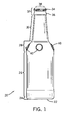
- FIG. 1 is a side plan view of a container showing the various elements of the container several of which are relevant to the out-of-round detection system of the present invention
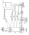
- FIG. 2 is a functional schematic showing the various components of the out-of-round detection system of the present invention.
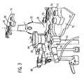
- FIG. 3 is an isometric view of a portion of a first type of an inspection station of a container manufacturing system having the sensor of the out-of-round detection system of the present invention installed therein, also showing a first type of container rotation drive for rotating containers;
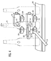
- FIG. 4 is an isometric view of a portion of a second type of an inspection station of a container manufacturing system having two sensors of the out-of-round detection system of the present invention installed therein, also showing a second type of container rotation drive for rotating containers;
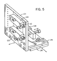
- FIG. 5 is an isometric view of a panel having two sensors mounted thereupon, the panel being adjustable in position to facilitate use of the sensors with different types of containers;
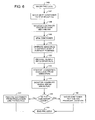
- FIG. 6 is a flow diagram describing the operation of the out-of-round detection system of the present invention.
- An exemplary embodiment of the present invention may be used with containers including, but not limited to glass bottles.
- containers including, but not limited to glass bottles.
- the container 20 illustrated in FIG. 1 is a glass beverage bottle, and the elements of its construction will be referred to from the bottom to the top.
- the bottom of the container 20 is referred to as the base 22 of the container 20, and the rounded portion where the horizontal plane of the base 22 transitions into a vertical cylinder is referred to as the heel 24 (and is also known as the insweep) of the container 20.
- the main content containing portion of the container 20, which is located above the heel 24, is the body 26 of the container 20.
- the body 26 of the container 20, which is essentially cylindrical in configuration, is also referred to as the label panel, since it is the body 26 upon which a label (not shown herein) will typically be placed.
- the shoulder 28 of the container 20 Located above the body 26 is the portion of the container 20 that curves inwardly to a reduced diameter, which is referred to as the shoulder 28 of the container 20.
- the shoulder 28 is the transition between the body 26 of the container 20 and the neck 30 of the container 20, and the neck 30 lies above the shoulder 28 and typically tapers inwardly toward the top of the container 20.
- the neck 30 of the container 20 is typically at least somewhat constricted as compared to the body 26 of the container 20.
- the portion of the container 20 that is located above the neck 30 of the container 20 is referred to as the finish 32 of the container 20.
- the finish 32 of the container 20 illustrated in FIG. 1 has two subcomponents. The uppermost of these two subcomponents of the finish 32 is referred to as the lip 34 (and is also known as the rim), and is located at the top of the container 20. It may be seen that the lip 34 on the container 20 shown in FIG. 1 is threaded, although other containers may have closure arrangements differing from that of the container 20 shown in FIG. 1 .
- the lowermost subcomponent of the finish 32 is referred to as the collar 36 (and is also known as the string rim), and the collar 36 on the container 20 may be seen to be somewhat outwardly projecting.
- the bore 38 (also known as the throat), which is the opening in the container 20 from which the contents of the container 20 will be accessed.
- the container 20 also has several raised embossed logos 40 located on the shoulder 28 of the container 20 that are evenly distributed around the circumference of the shoulder 28.
- an exemplary out-of-round detection system constructed according to the teachings of the present invention is illustrated as a functional schematic that shows the various components of the exemplary out-of-round detection system.
- the sensors used by the out-of-round detection system of the present invention are ultrasonic proximity sensors that are capable of sensing the distance from the sensor to an object with a high degree of accuracy and processing that information to provide a continuous digital output indicative of whether or not the distance detected is within a programmed range.
- One such sensor is the Model SC650A-B00 ultrasonic proximity sensor from Hyde Park Electronics LLC, of Dayton, Ohio. (Those skilled in the art will appreciate that the proximity sensor and the processing function could instead be located in two discreet devices.)
- the Model SC650A-B00 ultrasonic proximity sensor is a self-contained ultrasonic proximity sensor that is software configurable using a configurator interface module such as the Model AC441A configurator interface module, also available from Hyde Park Electronics LLC.
- the configurator interface module is used to program a desired distance range into the ultrasonic proximity sensor(s).
- the container 20 being checked will be a nominal distance X away from the ultrasonic proximity sensor(s).
- a range of distances between the ultrasonic proximity sensor(s) and the container 20 that is between X-Y and X+Y may be established.
- the ultrasonic proximity sensor(s) will produce a first output (high or low) when the distance between the ultrasonic proximity sensor(s) and the container 20 is between X-Y and X+Y, and a different second output (low or high) when the distance between the ultrasonic proximity sensor(s) and the container 20 is either less than X-Y or more than X+Y.
- the ultrasonic proximity sensor(s) By rotating the container 20 while operating the ultrasonic proximity sensor(s), it can thereby be determined whether the container 20 is within the established out-of-round tolerance, in which case the first output will be continuously produced, or outside of the established out-of-round tolerance, in which case the second output will occur during at least a portion of the rotation of the container 20, indicating that the container 20 is unacceptable from a quality standpoint.
- the software configurable ultrasonic proximity sensor also has a hysteresis function programmed thereinto.
- the purpose of using such a function is to allow the out-of-round detection system of the present invention to avoid making a false rejection of a container due to a normal container characteristic such as container seams that are located at the position at which the mold halves met each other. This is accomplished by requiring that any occurrence of a sensed distance between the ultrasonic proximity sensor and the container that is either less than X-Y or more than X+Y occur for a sufficient duration (which may be either a rotational duration or a time duration) to ensure that it is an out-of-round container that is being detected rather than merely the detection of the presence of a seam or other normal container characteristic.
- a first sensor 50 is positioned the nominal distance X away from the position at which the container 20 to be checked will be located.
- the first sensor 50 of the preferred embodiment includes both a sensor and a processor, which could instead be in two separate elements.
- the first sensor 50 is oriented orthogonally with respect to the axis of the container 20.
- the first sensor 50 will be used to check the roundness of the body 26 of the container 20.
- the operational parameters of the first sensor 50 are set using a configurator interface module 52, which, as indicated by the dotted line between the configurator interface module 52 and the first sensor 50, need only be connected to the first sensor 50 when the operational parameters of the first sensor 50 are initially being set or are being changed for a different size container.
- the output of the first sensor 50 is supplied to a signal combiner / conditioner 54, which, in the case of the first example, functions only as a signal conditioner since only the input from the first sensor 50 is supplied to it.
- the output of the signal combiner / conditioner 54 is supplied through a channel card 56 to a control / processing system 58.
- the channel card 56 is one of a plurality of inputs to the control / processing system 58, the others of which are not shown herein.
- the control / processing system 58 operates a container rotation drive 60 that is used to selectively rotate the container 20. It will be appreciated by those skilled in the art that a container is moved into a position for the out-of-round detection system of the present invention to check its roundness. The container rotation drive 60 then rotates the container 20, typically approximately one and one-half rotations in order to ensure that the roundness of the entire container 20 is checked.
- the first sensor 50 will continuously monitor the distance between the container 20 and the first sensor 50, and will provide its output signal to the signal combiner / conditioner 54, which provides an output through the channel card 56 to the control / processing system 58. If the output of the first sensor 50 at any point during the rotation of the container 20 produces the second output indicating that the distance between the first sensor 50 and the container 20 is either less than X-Y or more than X+Y, the control / processing system 58 will initiate the operation of a reject mechanism 62 that will cause the container 20 to be rejected (and, typically, recycled).
- control / processing system 58 includes data correlation and container tracking capabilities, which enable a rejected container to be removed from the stream of containers that pass the roundness check at a point downstream of the out-of-round detection system of the present invention. It will also be understood that the control / processing system 58 may also have inputs from other types of sensors that may be used to monitor other quality standards, such as, for example, the optical inspection taught in the above-incorporated by reference U.S. Patent No. 6,031,221, to Furnas . Should a container fail any one or more of the inspections being carried out upon it, it will be rejected. The operation of the reject mechanism 62 is also of conventional design in the art, and will therefore not be described in detail herein.
- a second sensor 64 as well as the first sensor 50 is positioned the nominal distance X away from the position at which the container 20 to be checked will be located.
- both the first sensor 50 and the second sensor 64 of the preferred embodiment each include both a sensor and a processor, which could instead be in two separate elements.
- the second sensor 64 and the first sensor 50 are respectively located such that they will scan different portions of the body 26 of the container 20.
- the first sensor 50 and the second sensor 64 are oriented orthogonally with respect to the axis of the container 20.
- the second sensor 64 and the first sensor 50 are shown respectively scanning the bottom portion and the intermediate portion of the body 26 of the container 20, if only these two sensors are used, they will likely be positioned to respectively scan the lower portion and the upper portion of the body 26 of the container 20. In this case, both the second sensor 64 and the first sensor 50 will be used to check the roundness of the body 26 of the container 20.
- the operational parameters of the second sensor 64 are also set using the configurator interface module 52, which, as indicated by the dotted line between the configurator interface module 52 and the second sensor 64, need only be connected to the second sensor 64 when the operational parameters of the second sensor 64 are initially being set or are being changed for a different size container.
- the outputs of the first sensor 50 and the second sensor 64 are supplied to the signal combiner / conditioner 54, which will provide an output indicating a defect whenever either one (or both) of the first sensor 50 and the second sensor 64 produces the second output indicating that the distance between the sensor in question and the container 20 is either less than X-Y or more than X+Y, thereby causing the control /processing system 58 to initiate the operation of the reject mechanism 62 to cause the container 20 to be rejected.
- a third sensor 66 as well as the first sensor 50 and the second sensor 64 is positioned the nominal distance X away from the position at which the container 20 to be checked will be located.
- the first sensor 50, the second sensor 64, and the third sensor 66 and of the preferred embodiment each include both a sensor and a processor, which could instead be in two separate elements.
- the first sensor 50, the second sensor 64, and the third sensor 66 are respectively located such that they will scan different portions of the body 26 of the container 20.
- the first sensor 50, the second sensor 64, and the third sensor 66 are oriented orthogonally with respect to the axis of the container 20.
- the first sensor 50, the second sensor 64, and the third sensor 66 will respectively scan the intermediate portion, the bottom portion, and the top portion of the body 26 of the container 20. In this case, all three of the first sensor 50, the second sensor 64, and the third sensor 66 will be used to check the roundness of the body 26 of the container 20.
- the operational parameters of the third sensor 66 are also set using the configurator interface module 52, which, as indicated by the dotted line between the configurator interface module 52 and the third sensor 66, need only be connected to the third sensor 66 when the operational parameters of the third sensor 66 are initially being set or are being changed for a different size container.
- the outputs of the first sensor 50, the second sensor 64, and the third sensor 66 are supplied to the signal combiner /conditioner 54, which will provide an output indicating a defect whenever any one (or more) of the first sensor 50, the second sensor 64, and the third sensor 66 produces the second output indicating that the distance between the sensor in question and the container 20 is either less than X-Y or more than X+Y, thereby causing the control / processing system 58 to initiate the operation of the reject mechanism 62 to cause the container 20 to be rejected.
- a fourth sensor 68 is positioned the nominal distance X away from the shoulder 28 of the container 20 to be checked will be located.
- the first sensor 50, the second sensor 64, the third sensor 66, and the fourth sensor 68 of the preferred embodiment each include both a sensor and a processor, which could instead be in two separate elements.
- the fourth sensor 68 is positioned as orthogonally to the surface of the container 20 at the shoulder 28 (and the location of the raised embossed logos 40 on the shoulder 28) as is possible.
- the axis of the fourth sensor 68 will intersect the axis of the container 20, it will do so at an angle rather than orthogonally.
- the fourth sensor 68 can be used in conjunction with any one, two, or all three of the first sensor 50, the second sensor 64, and the third sensor 66.
- the operational parameters of the fourth sensor 68 are also set using the configurator interface module 52, which, as indicated by the dotted line between the configurator interface module 52 and the fourth sensor 68, need only be connected to the fourth sensor 68 when the operational parameters of the fourth sensor 68 are initially being set or are being changed for a different size container.
- the outputs of the first sensor 50, the second sensor 64 (if used), the third sensor 66 (if used), and the fourth sensor 68 are supplied to the signal combiner /conditioner 54, which will provide an output indicating a defect whenever any one (or more) of the first sensor 50, the second sensor 64 (if used), the third sensor 66 (if used), and the fourth sensor 68 produces the second output indicating that the distance between the sensor in question and the container 20 is either less than X-Y or more than X+Y, thereby causing the control / processing system 58 to initiate the operation of the reject mechanism 62 to cause the container 20 to be rejected.
- FIG. 3 part of a first type of an inspection station used in a container manufacturing system and having a first type of container rotation drive for rotating containers is illustrated.
- a container 20 is shown to be resting on a deadplate 70 and is engaged by a starwheel 72 near the bottom of the container 20 and by a second starwheel 74 near the top of the container.
- Two rollers 76 and 78 are located on the starwheel 72, and the container 20 is engaged near its bottom by these rollers 76 and 78.
- Two additional rollers 80 and 82 are located on the starwheel 74, and the container 20 is engaged near its top by these rollers 80 and 82. It will be appreciated by those skilled in the art that the starwheels 72 and 74 both rotate to bring the container 20 into position in the inspection station for the out-of-round check.
- a drive roller 84 contacts the container 20 on the side opposite its support by the rollers 76 and 78 on the starwheel 72 and the rollers 80 and the roller 82 on the starwheel 74.
- the drive roller 84 is driven by a drive mechanism 86 which is supported by support apparatus indicated generally by the reference numeral 88.
- the first sensor 50 is mounted on a sensor clamp 90, which is supported in its fixed position by a support apparatus 92. The first sensor 50 is oriented toward the midpoint of the body 26 of the container 20, and is located orthogonal to the surface of the body 26 of the container 20.
- the drive roller 84 will cause the container 20 to rotate between the drive roller 84 and the rollers 76 and 78 (at the bottom of the container 20) and the rollers 80 and 82 (at the top of the container 20).
- the distance between the body 26 of the container 20 and the first sensor 50 will be detected by the first sensor 50, and from this it may be determined whether or not the container 20 is out-of-round by more than a predetermined amount.
- the construction and operation of the apparatus to rotate the container 20 in FIG. 3 is of conventional design, and that it may be used with another type of sensor (not shown herein) located at the same inspection station if desired.
- FIG. 4 part of a second type of an inspection station used in a container manufacturing system and having a second type of container rotation drive for rotating containers is illustrated.
- a container 20 is shown to be resting on a conveyer 100 at the location of an inspection station.
- the container 20 is engaged by two rollers 102 and 104 on the far side as shown in FIG. 4 and near its bottom.
- Two additional rollers 106 and 108 engage the container 20 near its top on the far side as shown in FIG. 4 and near its bottom.
- a drive roller 110 contacts the container 20 on the side opposite its support by the rollers 102 and 104 at the bottom and the rollers 106 and the roller 108 at the top (its front side as shown in FIG. 4 ).
- the drive roller 110 is driven by a drive mechanism 112 which is supported by support apparatus indicated generally by the reference numeral 114.
- the first sensor 50 and the second sensor 64 are integrally mounted in sensor mounting boxes 116 and 118, which are supported adjacent to the back of the conveyer 100 as shown in FIG. 4 .
- This configuration of the first sensor 50 and the sensor mounting box 116, and the second sensor 64 and the sensor mounting box 118, is a commercially available one-piece flat pack sensor assembly from Hyde Park Electronics LLC.
- the first sensor 50 is oriented toward the upper portion of the body 26 of the container 20, and the second sensor 64 is oriented toward the lower portion of the body 26 of the container 20. Both the first sensor 50 and the second sensor 64 are located orthogonal to the surface of the body 26 of the container 20.
- the drive roller 110 will cause the container 20 to rotate between the drive roller 110 and the rollers 102 and 104 (at the bottom of the container 20) and the rollers 106 and 108 (at the top of the container 20).
- the distance between the upper portion of the body 26 of the container 20 and the first sensor 50 will be detected by the first sensor 50
- the distance between the lower portion of the body 26 of the container 20 and the second sensor 64 will be detected by the second sensor 64, and from this it may be determined whether or not the container 20 is out-of-round by more than a predetermined amount.
- the construction and operation of the apparatus to rotate the container 20 in FIG. 4 is also of conventional design, and that it may be used with another type of sensor (not shown herein) located at the same inspection station if desired.
- FIG. 5 an alternative mounting system for the first sensor 50 and the second sensor 64 is illustrated.
- the objective of this mounting system is to allow adjustment of the position of the first sensor 50 and the second sensor 64.
- the first sensor 50 is mounted in a first sensor mounting box 120
- the second sensor 64 is mounted in a second sensor mounting box 122.
- the first sensor mounting box 120 and the second sensor mounting box 122 are mounted on a panel 124 having foot members 126 and 128.
- the foot members 126 and 128 are mounted on a base member 130 in a manner allowing lateral adjustment of the panel 124 as well as the first sensor 50 and the second sensor 64.
- the panel 124 itself has multiple mount positions for the first sensor 50 and the second sensor 64 to allow vertical position adjustment, and placement of the base member 130 relative to the position at which a container 20 will be located allows an adjustment of the distance between the first sensor 50 and the second sensor 64 and the container 20 to be checked. Such adjustments are shown schematically in FIG. 5 .
- the process begins with a process initiation step 140.
- a container 20 (shown in FIGS. 1 through 4 ) is brought into position for testing by the out-of-round detection system of the present invention in an inspection station (such as the ones shown in FIGS. 3 and 4 ) in a move next container to test position step 142.
- the container 20 is engaged by the rotation mechanism at the testing station (such as the rotation mechanisms shown in FIGS. 3 and 4 ) in an engage container with rotation mechanism step 144.
- the container 20 is rotated by the rotation mechanism in a spin container step 146.
- the container 20 is typically rotated approximately one and one-half rotations in order to ensure that the roundness of the entire container 20 is checked.
- the proximity sensor(s) (which may be any one or more of the first sensor 50, the second sensor 64, the third sensor 66, and the fourth sensor 68) is (are) operated to continuously monitor the distance between the sensor(s) and the container 20 in an operate sensor(s) to detect bottle surface position step 148.
- the sensor(s) monitor the distance between the sensor(s) and the container 20, the sensor(s) continuously provide an output indicating whether the distance between the proximity sensor(s) and the container 20 is within the desired tolerance or outside the desired tolerance in a provide output from sensor(s) step 150.
- the signals from the sensors will be combined and conditioned in a combine / condition signal(s) from sensor(s) step 152 (which is performed by the signal combiner / conditioner 54 shown in FIG. 2 ).
- the output of the combine / condition signal(s) from sensor(s) step 152 will indicate that the container 20 is outside the desired tolerance.
- the output of that sensor will be the output of the combine / condition signal(s) from sensor(s) step 152, and only signal conditioning will be provided therein.
- the combined signal from the sensor(s) is monitored in a monitor combined signal from sensor(s) step 154 (which is performed by the channel card 56 and the control / processing system 58 shown in FIG. 2 ).
- the control / processing system 58 will also make a determination as to whether the container is good based upon the combined signal in an is the container good determination step 156. If it is determined that the container 20 is good, the container 20 is allowed to move to finished goods in a move container to finished product location step 158, with the process then terminating in a process termination step 160.
- the container good determination step 156 determines whether the container 20 is out-of-round and thus is defective. If, on the other hand, it is determined in the is the container good determination step 156 that the container 20 is out-of-round and thus is defective, the container 20 is discarded in a remove container from production line to recycle step 162, with the process then moving to the process termination step 160.
- the out-of-round detection system of the present invention is capable of making such a determination without physically contacting the containers, and the determination is made both quickly and with a high degree of accuracy.
- the out-of-round detection system of the present invention is also capable of implementation in a large scale container production facility.
- the out-of-round detection system of the present invention is adaptable to different types of containers that may be manufactured at different times in a container production facility.
- the out-of-round detection system of the present invention is adjustable in tolerance to accommodate the inspection of different types of containers that have tighter or less stringent roundness requirements.
- the out-of-round detection system of the present invention is also capable of evaluating the roundness of different elements of containers.
- the out-of-round detection system of the present invention is of a construction which is both durable and long lasting, and which will require little or no maintenance to be provided by the user throughout its operating lifetime.
- the out-of-round detection system of the present invention is also of inexpensive construction to enhance its market appeal and to thereby afford it the broadest possible market.
Landscapes
- Physics & Mathematics (AREA)
- General Physics & Mathematics (AREA)
- Length Measuring Devices With Unspecified Measuring Means (AREA)
- Length Measuring Devices Characterised By Use Of Acoustic Means (AREA)
Claims (13)
- Système d'inspection automatique de la rondeur de récipients, comprenant :un appareil (60) pour faire tourner un récipient autour d'un axe du récipient pendant que le récipient est en cours d'inspection à une station d'inspection ;un premier capteur de proximité ultrasonique (50) positionné à un emplacement fixe par rapport à ladite station d'inspection pour détecter la distance entre ledit premier capteur de proximité et le récipient en cours d'inspection à la station d'inspection pendant que le récipient est tourné ;ledit premier capteur de proximité ultrasonique étant orienté orthogonalement à l'axe du récipient ; etun premier processeur qui traite la distance détectée par ledit premier capteur de proximité (50) et fournit un premier signal de sortie qui indique si la distance détectée par ledit premier capteur de proximité est à l'intérieur d'une première plage prédéterminée de distances ou pas ;dans lequel :le récipient (20), lorsqu'il est inspecté à la station d'inspection, est situé à une distance nominale X dudit premier capteur de proximité (50), et une tolérance Y de rondeur parfaite est acceptable pour le récipient, et ladite première plage prédéterminée de distances comprend :la plage de distances entre X-Y et X+Y ;le premier processeur fournit un premier signal de sortie lorsque la distance entre ledit premier capteur de proximité (50) et le récipient (20) est entre X-Y et X+Y, et un deuxième signal de sortie différent lorsque la distance entre ledit premier capteur de proximité et le récipient est soit inférieure à X-Y soit supérieure à X+Y ; etledit premier processeur a une fonction d'hystérésis de telle manière que toute survenance d'une distance détectée entre ledit premier capteur de proximité (50) et le récipient (20) en cours d'inspection qui est soit inférieure à X-Y soit supérieure à X+Y doit survenir pendant une durée minimale de rotation de récipient avant que ledit premier processeur ne fournisse ledit deuxième signal de sortie.
- Système selon la revendication 1, dans lequel ledit appareil (60) de rotation d'un récipient (20) est actionné pour faire tourner un récipient d'au moins un tour pendant que ledit premier capteur de proximité (50) détecte la distance entre ledit capteur et le récipient en cours d'inspection.
- Système selon la revendication 1 ou 2, dans lequel ledit appareil de rotation du récipient comprend :deux paires de rouleaux espacés l'un de l'autre (76, 78, 80, 82 ; 102, 104, 106, 108) pour se mettre en prise avec le récipient à l'extérieur de celui-ci ; etun rouleau d'entraînement (84 ; 110) pour se mettre en prise avec le récipient et le faire tourner tout en maintenant le récipient contre lesdites deux paires de rouleaux espacés l'un de l'autre, en définissant de ce fait un axe de rotation moyen en fonction de la géométrie du récipient et de l'espacement entre lesdites deux paires de rouleaux espacés l'un de l'autre et ledit rouleau d'entraînement.
- Système selon la revendication 1, 2 ou 3, dans lequel ledit premier capteur de proximité (50) est situé orthogonalement à une surface du récipient vers laquelle ledit premier capteur de proximité est orienté.
- Système selon l'une quelconque des revendications précédentes, dans lequel le récipient (20) comporte un épaulement (28) situé entre un corps (26) du récipient et un goulot (30) du récipient, et dans lequel ledit premier capteur de proximité (50) est orienté vers le corps ou l'épaulement du récipient, ou vers au moins un logo gaufré en relief (40) s'il est fourni sur le récipient.
- Système selon l'une quelconque des revendications précédentes, dans lequel ledit premier capteur de proximité (50) et ledit premier processeur sont intégrés dans un dispositif unique.
- Système selon l'une quelconque des revendications précédentes, comprenant en outre :un dispositif de programmation (52) pour une liaison amovible avec ledit premier processeur afin de programmer ladite première plage prédéterminée de distances.
- Système selon l'une quelconque des revendications précédentes, comprenant en outre :un processeur de commande (58), dans lequel ledit processeur de commande (58) actionne ledit appareil (60) pour faire tourner un récipient ; etune carte de canal d'interface (56) pour fournir ledit premier signal de sortie au dit processeur de commande (58) ;dans lequel ledit processeur de commande est capable d'accepter un signal de sortie d'un autre type de capteur en plus dudit premier signal de sortie.
- Système selon l'une quelconque des revendications précédentes, comprenant en outre :un deuxième capteur de proximité (64) positionné à un emplacement fixe par rapport à ladite station d'inspection pour détecter la distance entre ledit deuxième capteur de proximité et le récipient en cours d'inspection à la station d'inspection pendant que le récipient est tourné ; etun deuxième processeur qui traite la distance détectée par ledit deuxième capteur de proximité (64) et fournit un deuxième signal de sortie indiquant si la distance détectée par ledit deuxième capteur de proximité est à l'intérieur d'une deuxième plage prédéterminée de distances.
- Système selon la revendication 9, dans lequel ledit premier capteur de proximité (50) est orienté vers un premier emplacement sur la surface du récipient (20) et ledit deuxième capteur de proximité (64) est orienté vers un deuxième emplacement sur la surface du récipient qui est différent dudit premier emplacement sur la surface du récipient.
- Système selon la revendication 9 ou 10, comprenant en outre :un combineur de signaux (54) pour combiner ledit premier signal de sortie et ledit deuxième signal de sortie, dans lequel ledit combineur de signaux produit un premier signal de sortie de combineur de signaux ou un deuxième signal de sortie de combineur de signaux, dans lequel ledit premier signal de sortie de combineur de signaux indique que la distance détectée par ledit premier capteur de proximité (50) est à l'intérieur de la première plage prédéterminée de distances et la distance détectée par ledit deuxième capteur de proximité (64) est à l'intérieur de la deuxième plage prédéterminée de distances, et dans lequel ledit deuxième signal de sortie de combineur de signaux indique que la distance détectée par ledit premier capteur de proximité (50) n'est pas à l'intérieur de la première plage prédéterminée de distances ou la distance détectée par ledit deuxième capteur de proximité (64) n'est pas à l'intérieur de la deuxième plage prédéterminée de distances.
- Système selon la revendication 9, 10 ou 11, comprenant en outre :au moins un autre capteur de proximité (66, 68) positionné à un emplacement fixe par rapport à ladite station d'inspection pour détecter la distance entre ledit au moins un autre capteur de proximité et le récipient en cours d'inspection à la station d'inspection pendant que le récipient est tourné ; etau moins un autre processeur qui traite la distance détectée par ledit au moins un autre capteur de proximité (66, 68) et fournit au moins un autre signal de sortie indiquant si la distance détectée par ledit au moins un autre capteur de proximité est à l'intérieur d'au moins une autre plage prédéterminée de distances.
- Procédé d'inspection automatique de la rondeur de récipients, comprenant :la rotation d'un récipient autour d'un axe du récipient, le récipient étant en cours d'inspection à une station d'inspection ;la détection de la distance entre un capteur de proximité ultrasonique (50) et le récipient en cours d'inspection à la station d'inspection pendant que le récipient est tourné, ledit capteur de proximité étant positionné à un emplacement fixe par rapport à ladite station d'inspection et étant orienté orthogonalement à l'axe du récipient ; etle traitement de la distance détectée par ledit capteur de proximité (50) et la détermination si la distance détectée entre le capteur et le récipient est à l'intérieur d'une plage prédéterminée de distances et la délivrance d'un signal de sortie indiquant si la distance détectée par ledit capteur de proximité est à l'intérieur de la plage prédéterminée de distances ;dans lequel :le procédé comprend la fourniture d'une fonction d'hystérésis de telle manière que toute survenance d'une distance détectée entre le capteur de proximité (50) et le récipient (20) en cours d'inspection qui est à l'extérieur de ladite plage prédéterminée doit survenir pendant une durée minimale spécifiée de rotation de récipient avant de fournir un signal de sortie indiquant que la distance détectée est à l'extérieur de ladite plage prédéterminée.
Applications Claiming Priority (1)
| Application Number | Priority Date | Filing Date | Title |
|---|---|---|---|
| US12/120,025 US8548771B2 (en) | 2008-05-13 | 2008-05-13 | Out-of-round container detection system and method |
Publications (2)
| Publication Number | Publication Date |
|---|---|
| EP2120006A1 EP2120006A1 (fr) | 2009-11-18 |
| EP2120006B1 true EP2120006B1 (fr) | 2015-08-12 |
Family
ID=40911026
Family Applications (1)
| Application Number | Title | Priority Date | Filing Date |
|---|---|---|---|
| EP09158966.3A Not-in-force EP2120006B1 (fr) | 2008-05-13 | 2009-04-28 | Système et procédé de détection d'excentricité de récipient |
Country Status (3)
| Country | Link |
|---|---|
| US (1) | US8548771B2 (fr) |
| EP (1) | EP2120006B1 (fr) |
| JP (1) | JP2009276348A (fr) |
Families Citing this family (3)
| Publication number | Priority date | Publication date | Assignee | Title |
|---|---|---|---|---|
| US9574864B2 (en) | 2015-03-27 | 2017-02-21 | International Business Machines Corporation | Gauge for installation of liners in substrate spin coating tools |
| US10012598B2 (en) | 2015-07-17 | 2018-07-03 | Emhart S.A. | Multi-wavelength laser check detection tool |
| CN110319981B (zh) * | 2019-08-15 | 2021-01-12 | 浙江万众消防器材有限公司 | 一种阀门生产制造密封性通用检测设备及方法 |
Family Cites Families (19)
| Publication number | Priority date | Publication date | Assignee | Title |
|---|---|---|---|---|
| US3221544A (en) * | 1963-06-10 | 1965-12-07 | Southwest Res Inst | Ultrasonic inspection system |
| US4046258A (en) | 1976-07-02 | 1977-09-06 | Owens-Illinois, Inc. | Method and apparatus for measuring the eccentricity of containers |
| US4378494A (en) * | 1980-11-07 | 1983-03-29 | Owens-Illinois, Inc. | Apparatus and method for detecting defects in glass bottles using event proximity |
| US4368641A (en) | 1981-01-30 | 1983-01-18 | Powers Manufacturing, Inc. | Out-of-round detector |
| US4557386A (en) * | 1983-06-27 | 1985-12-10 | Cochlea Corporation | System to measure geometric and electromagnetic characteristics of objects |
| JPS61189444A (ja) * | 1985-02-18 | 1986-08-23 | Daiwa Senko Kk | 織物等シ−ト状物の表面傷検出方法 |
| JPS62167402A (ja) * | 1986-09-08 | 1987-07-23 | Toyo Glass Kk | びん胴径検査装置 |
| US4820972A (en) | 1987-07-02 | 1989-04-11 | Emhart Industries, Inc. | Wall thickness detector |
| CH687482A5 (de) * | 1994-01-19 | 1996-12-13 | Martin Lehmann | Verfahren zum Inspizieren rotationssymmetrischer, insbesondere zylindrischer Behaeltnisse und Inspektionsanordnung hierfuer. |
| US5591462A (en) | 1994-11-21 | 1997-01-07 | Pressco Technology, Inc. | Bottle inspection along molder transport path |
| US6031221A (en) | 1998-02-19 | 2000-02-29 | Emhart Glass S.A. | Container inspection machine |
| US6662961B2 (en) * | 2002-03-07 | 2003-12-16 | Graham Packaging Company, L.P. | Plastic container having structural ribs |
| US20030177850A1 (en) | 2002-03-19 | 2003-09-25 | The Washington Post Company | System and method for verifying the roll roundness of rolls of paper used for newspapers |
| US6808060B1 (en) | 2003-06-30 | 2004-10-26 | Emhart Glass S.A. | Container inspection machine |
| US6915894B2 (en) | 2003-06-30 | 2005-07-12 | Emhart Glass S.A. | Container inspection machine |
| US6989857B2 (en) | 2003-06-30 | 2006-01-24 | Emhart Glass S.A. | Container inspection machine |
| US7321679B2 (en) | 2004-07-02 | 2008-01-22 | Emhart Glass Sa | Machine for inspecting glass bottles |
| US7060999B2 (en) | 2004-07-09 | 2006-06-13 | Owens-Brockway Glass Container Inc. | Apparatus and method for inspecting ribbed containers |
| US20070115467A1 (en) | 2005-11-23 | 2007-05-24 | Owens-Brockway Glass Container | Apparatus and method for ensuring rotation of a container during inspection |
-
2008
- 2008-05-13 US US12/120,025 patent/US8548771B2/en not_active Expired - Fee Related
-
2009
- 2009-04-28 EP EP09158966.3A patent/EP2120006B1/fr not_active Not-in-force
- 2009-05-13 JP JP2009116109A patent/JP2009276348A/ja active Pending
Also Published As
| Publication number | Publication date |
|---|---|
| US8548771B2 (en) | 2013-10-01 |
| US20090287439A1 (en) | 2009-11-19 |
| EP2120006A1 (fr) | 2009-11-18 |
| JP2009276348A (ja) | 2009-11-26 |
Similar Documents
| Publication | Publication Date | Title |
|---|---|---|
| JP3040376B2 (ja) | 容器密封面領域検査方法及び装置 | |
| EP0793569B1 (fr) | Verification des bouteilles sur le chemin de transport de la machine a mouler | |
| EP1348932B1 (fr) | Procédé et machine pour vérifier l'épaisseur de la parois d'un récipient soufflé en matière synthétique | |
| US7329855B2 (en) | Optical inspection of glass bottles using multiple cameras | |
| US6473169B1 (en) | Integrated leak and vision inspection system | |
| US7330251B2 (en) | Method and apparatus for producing reference image in glass bottle inspecting apparatus | |
| EP2743689B1 (fr) | Procédé et appareil pour inspecter des produits en verre pendant la production | |
| US6049379A (en) | Method for inspecting translucent objects using imaging techniques | |
| WO2017204766A2 (fr) | Système de contrôle de qualité pour produits en verre semi-finis | |
| CN1102793A (zh) | 容器的检验和区分系统 | |
| EP2120006B1 (fr) | Système et procédé de détection d'excentricité de récipient | |
| WO2007061852A1 (fr) | Procede et appareil destines a l'inspection du profil des parois laterales d'un recipient | |
| JP7382519B2 (ja) | ガラスびんの検査方法及びガラスびんの製造方法並びにガラスびんの検査装置 | |
| TWI413754B (zh) | 用於確定於檢查期間容器旋轉的設備及方法 | |
| US11813644B2 (en) | Method and system for determining the manufacture of a glass container with its mold number | |
| JP2010133824A (ja) | キャップ検査装置及びキャップ検査方法 | |
| JP7185819B2 (ja) | 容器の検査方法 | |
| JP4815244B2 (ja) | びん検査機および製びん装置 | |
| JP2000103039A (ja) | 円筒容器の印刷検査装置 | |
| US20050015212A1 (en) | Multi machine inspection system | |
| JP3216720B2 (ja) | 透明容器におけるプレスしわのような欠陥の検出方法および装置 | |
| JP2024111741A (ja) | 搬送検査装置 | |
| JP2001074429A (ja) | ガラス壜の肉薄不良検査装置および検査方法 | |
| JP2003057014A (ja) | フランジ変形缶の検出方法 | |
| MXPA98003794A (en) | Inspection of the superficial sealing area of a recipie |
Legal Events
| Date | Code | Title | Description |
|---|---|---|---|
| PUAI | Public reference made under article 153(3) epc to a published international application that has entered the european phase |
Free format text: ORIGINAL CODE: 0009012 |
|
| AK | Designated contracting states |
Kind code of ref document: A1 Designated state(s): AT BE BG CH CY CZ DE DK EE ES FI FR GB GR HR HU IE IS IT LI LT LU LV MC MK MT NL NO PL PT RO SE SI SK TR |
|
| 17P | Request for examination filed |
Effective date: 20100507 |
|
| 17Q | First examination report despatched |
Effective date: 20100528 |
|
| GRAP | Despatch of communication of intention to grant a patent |
Free format text: ORIGINAL CODE: EPIDOSNIGR1 |
|
| INTG | Intention to grant announced |
Effective date: 20150303 |
|
| GRAS | Grant fee paid |
Free format text: ORIGINAL CODE: EPIDOSNIGR3 |
|
| GRAA | (expected) grant |
Free format text: ORIGINAL CODE: 0009210 |
|
| AK | Designated contracting states |
Kind code of ref document: B1 Designated state(s): AT BE BG CH CY CZ DE DK EE ES FI FR GB GR HR HU IE IS IT LI LT LU LV MC MK MT NL NO PL PT RO SE SI SK TR |
|
| REG | Reference to a national code |
Ref country code: GB Ref legal event code: FG4D |
|
| REG | Reference to a national code |
Ref country code: CH Ref legal event code: EP |
|
| REG | Reference to a national code |
Ref country code: AT Ref legal event code: REF Ref document number: 742565 Country of ref document: AT Kind code of ref document: T Effective date: 20150815 |
|
| REG | Reference to a national code |
Ref country code: IE Ref legal event code: FG4D |
|
| REG | Reference to a national code |
Ref country code: DE Ref legal event code: R096 Ref document number: 602009032766 Country of ref document: DE |
|
| REG | Reference to a national code |
Ref country code: LT Ref legal event code: MG4D |
|
| REG | Reference to a national code |
Ref country code: AT Ref legal event code: MK05 Ref document number: 742565 Country of ref document: AT Kind code of ref document: T Effective date: 20150812 |
|
| REG | Reference to a national code |
Ref country code: NL Ref legal event code: MP Effective date: 20150812 |
|
| PG25 | Lapsed in a contracting state [announced via postgrant information from national office to epo] |
Ref country code: GR Free format text: LAPSE BECAUSE OF FAILURE TO SUBMIT A TRANSLATION OF THE DESCRIPTION OR TO PAY THE FEE WITHIN THE PRESCRIBED TIME-LIMIT Effective date: 20151113 Ref country code: NO Free format text: LAPSE BECAUSE OF FAILURE TO SUBMIT A TRANSLATION OF THE DESCRIPTION OR TO PAY THE FEE WITHIN THE PRESCRIBED TIME-LIMIT Effective date: 20151112 Ref country code: LT Free format text: LAPSE BECAUSE OF FAILURE TO SUBMIT A TRANSLATION OF THE DESCRIPTION OR TO PAY THE FEE WITHIN THE PRESCRIBED TIME-LIMIT Effective date: 20150812 Ref country code: FI Free format text: LAPSE BECAUSE OF FAILURE TO SUBMIT A TRANSLATION OF THE DESCRIPTION OR TO PAY THE FEE WITHIN THE PRESCRIBED TIME-LIMIT Effective date: 20150812 Ref country code: LV Free format text: LAPSE BECAUSE OF FAILURE TO SUBMIT A TRANSLATION OF THE DESCRIPTION OR TO PAY THE FEE WITHIN THE PRESCRIBED TIME-LIMIT Effective date: 20150812 |
|
| PG25 | Lapsed in a contracting state [announced via postgrant information from national office to epo] |
Ref country code: PT Free format text: LAPSE BECAUSE OF FAILURE TO SUBMIT A TRANSLATION OF THE DESCRIPTION OR TO PAY THE FEE WITHIN THE PRESCRIBED TIME-LIMIT Effective date: 20151214 Ref country code: PL Free format text: LAPSE BECAUSE OF FAILURE TO SUBMIT A TRANSLATION OF THE DESCRIPTION OR TO PAY THE FEE WITHIN THE PRESCRIBED TIME-LIMIT Effective date: 20150812 Ref country code: IS Free format text: LAPSE BECAUSE OF FAILURE TO SUBMIT A TRANSLATION OF THE DESCRIPTION OR TO PAY THE FEE WITHIN THE PRESCRIBED TIME-LIMIT Effective date: 20151212 Ref country code: SE Free format text: LAPSE BECAUSE OF FAILURE TO SUBMIT A TRANSLATION OF THE DESCRIPTION OR TO PAY THE FEE WITHIN THE PRESCRIBED TIME-LIMIT Effective date: 20150812 Ref country code: HR Free format text: LAPSE BECAUSE OF FAILURE TO SUBMIT A TRANSLATION OF THE DESCRIPTION OR TO PAY THE FEE WITHIN THE PRESCRIBED TIME-LIMIT Effective date: 20150812 Ref country code: AT Free format text: LAPSE BECAUSE OF FAILURE TO SUBMIT A TRANSLATION OF THE DESCRIPTION OR TO PAY THE FEE WITHIN THE PRESCRIBED TIME-LIMIT Effective date: 20150812 Ref country code: ES Free format text: LAPSE BECAUSE OF FAILURE TO SUBMIT A TRANSLATION OF THE DESCRIPTION OR TO PAY THE FEE WITHIN THE PRESCRIBED TIME-LIMIT Effective date: 20150812 |
|
| PG25 | Lapsed in a contracting state [announced via postgrant information from national office to epo] |
Ref country code: NL Free format text: LAPSE BECAUSE OF FAILURE TO SUBMIT A TRANSLATION OF THE DESCRIPTION OR TO PAY THE FEE WITHIN THE PRESCRIBED TIME-LIMIT Effective date: 20150812 |
|
| REG | Reference to a national code |
Ref country code: FR Ref legal event code: PLFP Year of fee payment: 8 |
|
| PG25 | Lapsed in a contracting state [announced via postgrant information from national office to epo] |
Ref country code: DK Free format text: LAPSE BECAUSE OF FAILURE TO SUBMIT A TRANSLATION OF THE DESCRIPTION OR TO PAY THE FEE WITHIN THE PRESCRIBED TIME-LIMIT Effective date: 20150812 Ref country code: SK Free format text: LAPSE BECAUSE OF FAILURE TO SUBMIT A TRANSLATION OF THE DESCRIPTION OR TO PAY THE FEE WITHIN THE PRESCRIBED TIME-LIMIT Effective date: 20150812 Ref country code: EE Free format text: LAPSE BECAUSE OF FAILURE TO SUBMIT A TRANSLATION OF THE DESCRIPTION OR TO PAY THE FEE WITHIN THE PRESCRIBED TIME-LIMIT Effective date: 20150812 |
|
| REG | Reference to a national code |
Ref country code: DE Ref legal event code: R097 Ref document number: 602009032766 Country of ref document: DE |
|
| PG25 | Lapsed in a contracting state [announced via postgrant information from national office to epo] |
Ref country code: RO Free format text: LAPSE BECAUSE OF FAILURE TO SUBMIT A TRANSLATION OF THE DESCRIPTION OR TO PAY THE FEE WITHIN THE PRESCRIBED TIME-LIMIT Effective date: 20150812 |
|
| PLBE | No opposition filed within time limit |
Free format text: ORIGINAL CODE: 0009261 |
|
| STAA | Information on the status of an ep patent application or granted ep patent |
Free format text: STATUS: NO OPPOSITION FILED WITHIN TIME LIMIT |
|
| 26N | No opposition filed |
Effective date: 20160513 |
|
| PGFP | Annual fee paid to national office [announced via postgrant information from national office to epo] |
Ref country code: DE Payment date: 20160427 Year of fee payment: 8 Ref country code: CZ Payment date: 20160413 Year of fee payment: 8 Ref country code: GB Payment date: 20160427 Year of fee payment: 8 |
|
| PG25 | Lapsed in a contracting state [announced via postgrant information from national office to epo] |
Ref country code: BE Free format text: LAPSE BECAUSE OF NON-PAYMENT OF DUE FEES Effective date: 20160430 Ref country code: SI Free format text: LAPSE BECAUSE OF FAILURE TO SUBMIT A TRANSLATION OF THE DESCRIPTION OR TO PAY THE FEE WITHIN THE PRESCRIBED TIME-LIMIT Effective date: 20150812 |
|
| PGFP | Annual fee paid to national office [announced via postgrant information from national office to epo] |
Ref country code: FR Payment date: 20160425 Year of fee payment: 8 Ref country code: IT Payment date: 20160421 Year of fee payment: 8 |
|
| REG | Reference to a national code |
Ref country code: CH Ref legal event code: PL |
|
| PG25 | Lapsed in a contracting state [announced via postgrant information from national office to epo] |
Ref country code: BE Free format text: LAPSE BECAUSE OF FAILURE TO SUBMIT A TRANSLATION OF THE DESCRIPTION OR TO PAY THE FEE WITHIN THE PRESCRIBED TIME-LIMIT Effective date: 20150812 Ref country code: LU Free format text: LAPSE BECAUSE OF FAILURE TO SUBMIT A TRANSLATION OF THE DESCRIPTION OR TO PAY THE FEE WITHIN THE PRESCRIBED TIME-LIMIT Effective date: 20160428 |
|
| REG | Reference to a national code |
Ref country code: IE Ref legal event code: MM4A |
|
| PG25 | Lapsed in a contracting state [announced via postgrant information from national office to epo] |
Ref country code: LI Free format text: LAPSE BECAUSE OF NON-PAYMENT OF DUE FEES Effective date: 20160430 Ref country code: CH Free format text: LAPSE BECAUSE OF NON-PAYMENT OF DUE FEES Effective date: 20160430 |
|
| PG25 | Lapsed in a contracting state [announced via postgrant information from national office to epo] |
Ref country code: IE Free format text: LAPSE BECAUSE OF NON-PAYMENT OF DUE FEES Effective date: 20160428 |
|
| REG | Reference to a national code |
Ref country code: DE Ref legal event code: R119 Ref document number: 602009032766 Country of ref document: DE |
|
| GBPC | Gb: european patent ceased through non-payment of renewal fee |
Effective date: 20170428 |
|
| REG | Reference to a national code |
Ref country code: FR Ref legal event code: ST Effective date: 20171229 |
|
| PG25 | Lapsed in a contracting state [announced via postgrant information from national office to epo] |
Ref country code: CZ Free format text: LAPSE BECAUSE OF NON-PAYMENT OF DUE FEES Effective date: 20170428 Ref country code: FR Free format text: LAPSE BECAUSE OF NON-PAYMENT OF DUE FEES Effective date: 20170502 Ref country code: DE Free format text: LAPSE BECAUSE OF NON-PAYMENT OF DUE FEES Effective date: 20171103 |
|
| PG25 | Lapsed in a contracting state [announced via postgrant information from national office to epo] |
Ref country code: GB Free format text: LAPSE BECAUSE OF NON-PAYMENT OF DUE FEES Effective date: 20170428 |
|
| PG25 | Lapsed in a contracting state [announced via postgrant information from national office to epo] |
Ref country code: CY Free format text: LAPSE BECAUSE OF FAILURE TO SUBMIT A TRANSLATION OF THE DESCRIPTION OR TO PAY THE FEE WITHIN THE PRESCRIBED TIME-LIMIT Effective date: 20150812 Ref country code: HU Free format text: LAPSE BECAUSE OF FAILURE TO SUBMIT A TRANSLATION OF THE DESCRIPTION OR TO PAY THE FEE WITHIN THE PRESCRIBED TIME-LIMIT; INVALID AB INITIO Effective date: 20090428 Ref country code: IT Free format text: LAPSE BECAUSE OF NON-PAYMENT OF DUE FEES Effective date: 20170428 |
|
| PG25 | Lapsed in a contracting state [announced via postgrant information from national office to epo] |
Ref country code: MK Free format text: LAPSE BECAUSE OF FAILURE TO SUBMIT A TRANSLATION OF THE DESCRIPTION OR TO PAY THE FEE WITHIN THE PRESCRIBED TIME-LIMIT Effective date: 20150812 Ref country code: TR Free format text: LAPSE BECAUSE OF FAILURE TO SUBMIT A TRANSLATION OF THE DESCRIPTION OR TO PAY THE FEE WITHIN THE PRESCRIBED TIME-LIMIT Effective date: 20150812 Ref country code: MT Free format text: LAPSE BECAUSE OF NON-PAYMENT OF DUE FEES Effective date: 20160430 Ref country code: MC Free format text: LAPSE BECAUSE OF FAILURE TO SUBMIT A TRANSLATION OF THE DESCRIPTION OR TO PAY THE FEE WITHIN THE PRESCRIBED TIME-LIMIT Effective date: 20150812 |
|
| PG25 | Lapsed in a contracting state [announced via postgrant information from national office to epo] |
Ref country code: BG Free format text: LAPSE BECAUSE OF FAILURE TO SUBMIT A TRANSLATION OF THE DESCRIPTION OR TO PAY THE FEE WITHIN THE PRESCRIBED TIME-LIMIT Effective date: 20150812 |