EP2119943A2 - Control apparatus for hydraulic driving vehicle - Google Patents
Control apparatus for hydraulic driving vehicle Download PDFInfo
- Publication number
- EP2119943A2 EP2119943A2 EP09160017A EP09160017A EP2119943A2 EP 2119943 A2 EP2119943 A2 EP 2119943A2 EP 09160017 A EP09160017 A EP 09160017A EP 09160017 A EP09160017 A EP 09160017A EP 2119943 A2 EP2119943 A2 EP 2119943A2
- Authority
- EP
- European Patent Office
- Prior art keywords
- set value
- zone
- speed
- manipulated
- engine
- Prior art date
- Legal status (The legal status is an assumption and is not a legal conclusion. Google has not performed a legal analysis and makes no representation as to the accuracy of the status listed.)
- Granted
Links
- 238000006073 displacement reaction Methods 0.000 claims abstract description 65
- 239000010720 hydraulic oil Substances 0.000 claims abstract description 4
- 230000001133 acceleration Effects 0.000 claims description 16
- 239000000446 fuel Substances 0.000 abstract description 22
- 230000003247 decreasing effect Effects 0.000 description 7
- 238000001816 cooling Methods 0.000 description 3
- 239000003921 oil Substances 0.000 description 3
- 230000005540 biological transmission Effects 0.000 description 2
- 230000006866 deterioration Effects 0.000 description 2
- 238000010586 diagram Methods 0.000 description 2
- 230000000694 effects Effects 0.000 description 1
- 238000002347 injection Methods 0.000 description 1
- 239000007924 injection Substances 0.000 description 1
- 238000000034 method Methods 0.000 description 1
Images


Classifications
-
- F—MECHANICAL ENGINEERING; LIGHTING; HEATING; WEAPONS; BLASTING
- F16—ENGINEERING ELEMENTS AND UNITS; GENERAL MEASURES FOR PRODUCING AND MAINTAINING EFFECTIVE FUNCTIONING OF MACHINES OR INSTALLATIONS; THERMAL INSULATION IN GENERAL
- F16H—GEARING
- F16H61/00—Control functions within control units of change-speed- or reversing-gearings for conveying rotary motion ; Control of exclusively fluid gearing, friction gearing, gearings with endless flexible members or other particular types of gearing
- F16H61/38—Control of exclusively fluid gearing
- F16H61/40—Control of exclusively fluid gearing hydrostatic
- F16H61/46—Automatic regulation in accordance with output requirements
- F16H61/465—Automatic regulation in accordance with output requirements for achieving a target input speed
-
- B—PERFORMING OPERATIONS; TRANSPORTING
- B60—VEHICLES IN GENERAL
- B60W—CONJOINT CONTROL OF VEHICLE SUB-UNITS OF DIFFERENT TYPE OR DIFFERENT FUNCTION; CONTROL SYSTEMS SPECIALLY ADAPTED FOR HYBRID VEHICLES; ROAD VEHICLE DRIVE CONTROL SYSTEMS FOR PURPOSES NOT RELATED TO THE CONTROL OF A PARTICULAR SUB-UNIT
- B60W10/00—Conjoint control of vehicle sub-units of different type or different function
- B60W10/04—Conjoint control of vehicle sub-units of different type or different function including control of propulsion units
- B60W10/06—Conjoint control of vehicle sub-units of different type or different function including control of propulsion units including control of combustion engines
-
- B—PERFORMING OPERATIONS; TRANSPORTING
- B60—VEHICLES IN GENERAL
- B60W—CONJOINT CONTROL OF VEHICLE SUB-UNITS OF DIFFERENT TYPE OR DIFFERENT FUNCTION; CONTROL SYSTEMS SPECIALLY ADAPTED FOR HYBRID VEHICLES; ROAD VEHICLE DRIVE CONTROL SYSTEMS FOR PURPOSES NOT RELATED TO THE CONTROL OF A PARTICULAR SUB-UNIT
- B60W30/00—Purposes of road vehicle drive control systems not related to the control of a particular sub-unit, e.g. of systems using conjoint control of vehicle sub-units
- B60W30/18—Propelling the vehicle
- B60W30/188—Controlling power parameters of the driveline, e.g. determining the required power
- B60W30/1882—Controlling power parameters of the driveline, e.g. determining the required power characterised by the working point of the engine, e.g. by using engine output chart
-
- F—MECHANICAL ENGINEERING; LIGHTING; HEATING; WEAPONS; BLASTING
- F16—ENGINEERING ELEMENTS AND UNITS; GENERAL MEASURES FOR PRODUCING AND MAINTAINING EFFECTIVE FUNCTIONING OF MACHINES OR INSTALLATIONS; THERMAL INSULATION IN GENERAL
- F16H—GEARING
- F16H61/00—Control functions within control units of change-speed- or reversing-gearings for conveying rotary motion ; Control of exclusively fluid gearing, friction gearing, gearings with endless flexible members or other particular types of gearing
- F16H61/38—Control of exclusively fluid gearing
- F16H61/40—Control of exclusively fluid gearing hydrostatic
- F16H61/42—Control of exclusively fluid gearing hydrostatic involving adjustment of a pump or motor with adjustable output or capacity
- F16H61/431—Pump capacity control by electro-hydraulic control means, e.g. using solenoid valves
-
- F—MECHANICAL ENGINEERING; LIGHTING; HEATING; WEAPONS; BLASTING
- F16—ENGINEERING ELEMENTS AND UNITS; GENERAL MEASURES FOR PRODUCING AND MAINTAINING EFFECTIVE FUNCTIONING OF MACHINES OR INSTALLATIONS; THERMAL INSULATION IN GENERAL
- F16H—GEARING
- F16H61/00—Control functions within control units of change-speed- or reversing-gearings for conveying rotary motion ; Control of exclusively fluid gearing, friction gearing, gearings with endless flexible members or other particular types of gearing
- F16H61/38—Control of exclusively fluid gearing
- F16H61/40—Control of exclusively fluid gearing hydrostatic
- F16H61/46—Automatic regulation in accordance with output requirements
- F16H61/47—Automatic regulation in accordance with output requirements for achieving a target output speed
-
- B—PERFORMING OPERATIONS; TRANSPORTING
- B60—VEHICLES IN GENERAL
- B60W—CONJOINT CONTROL OF VEHICLE SUB-UNITS OF DIFFERENT TYPE OR DIFFERENT FUNCTION; CONTROL SYSTEMS SPECIALLY ADAPTED FOR HYBRID VEHICLES; ROAD VEHICLE DRIVE CONTROL SYSTEMS FOR PURPOSES NOT RELATED TO THE CONTROL OF A PARTICULAR SUB-UNIT
- B60W2520/00—Input parameters relating to overall vehicle dynamics
- B60W2520/10—Longitudinal speed
-
- F—MECHANICAL ENGINEERING; LIGHTING; HEATING; WEAPONS; BLASTING
- F16—ENGINEERING ELEMENTS AND UNITS; GENERAL MEASURES FOR PRODUCING AND MAINTAINING EFFECTIVE FUNCTIONING OF MACHINES OR INSTALLATIONS; THERMAL INSULATION IN GENERAL
- F16H—GEARING
- F16H59/00—Control inputs to control units of change-speed-, or reversing-gearings for conveying rotary motion
- F16H59/36—Inputs being a function of speed
- F16H2059/366—Engine or motor speed
-
- F—MECHANICAL ENGINEERING; LIGHTING; HEATING; WEAPONS; BLASTING
- F16—ENGINEERING ELEMENTS AND UNITS; GENERAL MEASURES FOR PRODUCING AND MAINTAINING EFFECTIVE FUNCTIONING OF MACHINES OR INSTALLATIONS; THERMAL INSULATION IN GENERAL
- F16H—GEARING
- F16H59/00—Control inputs to control units of change-speed-, or reversing-gearings for conveying rotary motion
- F16H59/68—Inputs being a function of gearing status
- F16H2059/6838—Sensing gearing status of hydrostatic transmissions
- F16H2059/6876—Sensing gearing status of hydrostatic transmissions the motor speed
-
- F—MECHANICAL ENGINEERING; LIGHTING; HEATING; WEAPONS; BLASTING
- F16—ENGINEERING ELEMENTS AND UNITS; GENERAL MEASURES FOR PRODUCING AND MAINTAINING EFFECTIVE FUNCTIONING OF MACHINES OR INSTALLATIONS; THERMAL INSULATION IN GENERAL
- F16H—GEARING
- F16H59/00—Control inputs to control units of change-speed-, or reversing-gearings for conveying rotary motion
- F16H59/36—Inputs being a function of speed
- F16H59/38—Inputs being a function of speed of gearing elements
- F16H59/42—Input shaft speed
-
- F—MECHANICAL ENGINEERING; LIGHTING; HEATING; WEAPONS; BLASTING
- F16—ENGINEERING ELEMENTS AND UNITS; GENERAL MEASURES FOR PRODUCING AND MAINTAINING EFFECTIVE FUNCTIONING OF MACHINES OR INSTALLATIONS; THERMAL INSULATION IN GENERAL
- F16H—GEARING
- F16H59/00—Control inputs to control units of change-speed-, or reversing-gearings for conveying rotary motion
- F16H59/36—Inputs being a function of speed
- F16H59/44—Inputs being a function of speed dependent on machine speed of the machine, e.g. the vehicle
Definitions
- the present invention relates to a control apparatus for a hydraulic driving vehicle, for example a wheel loader, a wheel crane and so on.
- a hydraulic transmission (HST) is used in this kind of hydraulic driving vehicle.
- an engine drives a variable displacement hydraulic pump.
- a hydraulic motor is driven by hydraulic oil supplied from the hydraulic pump.
- a driving speed detecting means detects a driving speed
- an engine rotating speed detecting means detects a rotation number of the engine.
- a control means controls a pump displacement based on a set value for pump displacement.
- the control means determines the set value for pump displacement by a certain function and the engine rotating speed.
- the function is set so as to make the set value in a high speed zone larger than the set value in a low speed zone.
- the high and low speed zones are determined by the driving speed detected by the driving speed detecting means.
- the engine rotating speed can be decreased by increasing the pump displacement in a high speed zone more than that in a low speed zone, it is possible to improve the fuel efficiency in a high speed vehicle like a wheel crane which frequently drives at a high speed. Moreover, it is possible to improve pump efficiency by increasing the pump displacement.
- rotating speeds of a cooling fan and an auxiliary pump also goes down because these devices are also driven by the engine. For this reason, energy loss caused by these devices is also decreased, so that the fuel efficiency becomes much better.
- the function of the control means is kept constant regardless of a change of the driving speed, either in a high speed zone where the driving speed is higher than an upper limit or in a low speed zone where it is lower than a lower limit, or both in the zones.
- control means controls the engine so as to keep the driving speed lower than the upper limit.
- an acceleration inputting means for inputting an acceleration signal and a manipulated accelerator amount detecting means are further provided.
- the manipulated acceleration amount detecting means detects the manipulated amount of the acceleration inputting means.
- the control means determines the set value for pump displacement with the function which sets the set value for pump displacement in a little manipulated accelerator zone so as to be larger than the set value for pump displacement in a large manipulated accelerator zone.
- the amount of manipulated accelerator is not more than a set value for manipulated accelerator amount.
- the amount is more than the set value for manipulated accelerator amount.
- control means keeps the function constant regardless of a change of manipulated accelerator amount, in an extra little acceleration zone where the manipulated accelerator amount is less than a lower limit of the little manipulated accelerator zone.
- FIG. 1 shows a driving system and a control system of the first embodiment.
- an engine 1 drives a variable displacement hydraulic pump 2.
- a variable displacement hydraulic motor 3 is driven by discharged oil of the hydraulic pump 2.
- the hydraulic pump 2 and the hydraulic motor 3 are connected each other with pipe lines 4 and 5 so as to form a close circuit.
- the rotation power of the hydraulic motor 3 is transmitted to wheels 7 via an axel 6.
- a power divider 8 divides a power of the engine 1 into powers for the hydraulic pump 2, for an auxiliary pump 9 and for a cooling fan 10.
- An acceleration inputting means 11 outputs to the engine 1 a signal showing the amount of accelerator manipulation.
- the acceleration inputting means 11 is an accelerator pedal.
- the signal from the acceleration inputting means 11 is inputted to an engine control portion 13 of a control means 12.
- the engine 1 rotates by conducting fuel injection at an accelerator opening degree corresponding to the signal.
- An engine rotation detecting means 15 detects a rotation number of the engine, and a driving speed detecting means 16 detects a driving speed.
- the engine rotation number and the driving speed, which are detected by both detecting means 15 and 16, are inputted to a pump control portion 14 of the control means 12.
- the pump control portion 14 selects a function deciding a set value for pump displacement, based on the detected engine rotation number and the detected driving speed. Based on the set value for pump displacement which is calculated with the function, the pump control portion 14 controls the displacement of the hydraulic pump 2.
- the displacement of the hydraulic pump 2 is controlled by the set value for pump displacement.
- the set value is calculated by multiplying the engine rotating speed by the determined function. Accordingly, the set value for pump displacement is determined, based on only the engine rotating speed. As shown with the mark "a” in Fig.2 , in the driving speed "V", the set value for pump displacement is determined by multiplying the engine rotating speed by the function "f1".
- the function regarding the engine rotating speed is varied in accordance with the driving speed. Accordingly, in a high driving speed zone where the driving speed is more than the set value "V", as shown with the mark "b" in Fig. 2 , the set value for pump displacement is determined by a function "f2" which is set so as to make the set value for pump displacement more than that of the function "f1". On the other hand, in a low driving speed zone where driving speed is less than the set value "V", as shown with the mark "c" in Fig.2 , the set value for pump displacement is determined by a function "f3" which is set so as to make the set value for pump displacement less than that of the function "f1". In other words, the set value for pump displacement in the high driving speed zone is larger than that in the low driving speed zone.
- the above-mentioned control changing the function is executed. For this reason, as shown in Fig.5 , because it is possible to decrease the engine rotating speed to a greater extent, the fuel efficiency is more improved in case of driving at a predetermined speed limit.
- the function keeps constant regardless of the change of driving speed in the zones where the driving speed is more than the upper limit or it is less than the lower limit.
- the pump displacement keeps within a constant range both in the high and low speed zones. Accordingly, it is possible to remove the disadvantage that the accelerating performance becomes worse by reason of too little pump displacement in the low speed zone. Moreover, it is also possible to remove the disadvantage that shortage of power or deterioration of engine efficiency by reason of too little engine rotating speed in the high speed zone makes fuel efficiency worse.
- the fuel efficiency is improved by decreasing the engine rotating speed.
- the amount of manipulated accelerator corresponds to a load occurred in driving.
- a manipulated accelerator amount detecting means 17 is added as another detecting means.
- the manipulated accelerator amount detecting means 17 detects the amount of manipulated accelerator by a signal from the acceleration inputting means 11.
- the amount of manipulated accelerator is transmitted to the pump control portion 14 together with the engine rotating speed and the driving speed.
- the pump control portion 14 determines the set value for pump displacement based on these signals.
- the set value for pump displacement is determined by a function "g1" in response to the engine rotating speed.
- the function varies in accordance with the manipulated accelerator amount. Accordingly, in a little manipulated accelerator zone where the manipulated accelerator amount is less than the set value "X”, as shown with the mark "b" in Fig.7 , the set value for pump displacement is determined by a function "g2" which is set so as to become larger than the set value for pump displacement determined by the function"g1".
- the set value for pump displacement is determined by a function "g3" which is set so as to become smaller than the set value for pump displacement determined by the function "g1".
- the control which uses the function corresponding to the driving speed as explained above as the first embodiment is executed as being in a high speed zone.
- a step S1 the detected manipulated accelerator amount and the set value "X" are compared each other.
- a step S2 is executed.
- a step S3 is executed.
- the set value for pump displacement is determined by the function "g2”.
- the set value for pump displacement is determined by the function "g3".
- the processes explained in the first embodiment are executed as being in the high speed zone. That is to say, in a step S4, the detected driving speed and the set value "V" are compared each other. In the case that the driving speed is not less than "V”, the set value for pump displacement is determined by the function "f2" in a step S5. In the case that the driving speed is less than "V”, the set value for pump displacement is determined by the function "f3" in a step S6.
- step S7 the set value for pump displacement is outputted, which is determined in one of the above steps S2, S5, S6.
- an engine 1 drives a variable displacement hydraulic pump 2.
- a hydraulic motor 3 is driven by hydraulic oil supplied from the hydraulic pump 2.
- a rotation number of the engine 1 is detected by an engine rotating speed detecting means 15, and a driving speed is detected by a driving speed detecting means 16.
- a control means 12 determines a set value for pump displacement of the hydraulic pump 2 by calculating with a function. The function is set so as to make the set value in a high speed zone larger than the set value in a low speed zone. Accordingly, in a HST type hydraulic driven vehicle, fuel efficiency is improved in the high speed zone.
Landscapes
- Engineering & Computer Science (AREA)
- General Engineering & Computer Science (AREA)
- Mechanical Engineering (AREA)
- Chemical & Material Sciences (AREA)
- Combustion & Propulsion (AREA)
- Transportation (AREA)
- Automation & Control Theory (AREA)
- Control Of Fluid Gearings (AREA)
- Motor Power Transmission Devices (AREA)
- Control Of Vehicle Engines Or Engines For Specific Uses (AREA)
Abstract
Description
- The present invention relates to a control apparatus for a hydraulic driving vehicle, for example a wheel loader, a wheel crane and so on.
- In general, a hydraulic transmission (HST) is used in this kind of hydraulic driving vehicle.
- In general HST technology, a relationship between an engine rotating speed and a pump displacement is previously determined. When the vehicle drives at a constant speed, the pump displacement is increased or decreased in accordance with a change of the engine rotating speed. In other words, the pump displacement is increased when the engine rotating speed becomes higher, and the pump displacement is decreased when it becomes lower.
- However, in the conventional technology which determines the pump displacement based on only the engine rotating speed, since it is impossible to control the pump displacement in response to the relationship with the driving speed, there was a problem that fuel consumption rate becomes worse, in particular, especially in high speed driving condition.
- As a technology whose object is to improve fuel consumption rate of a low speed vehicle like a folk-lift in a low driving speed zone, the technology described in Japanese Patent Laid-Open No.
Hei9-301016 - However, although the above-mentioned conventional technology is effective to the low speed vehicle, it was a problem that it is impossible to apply the technology for a high speed vehicle which frequently drives at a high speed, like a wheel loader or a wheel crane. In these kinds of high speed vehicles, the fuel efficiency becomes worse because the engine rotating speed becomes high in the high speed zone.
- It is an object of the present invention to provide a control apparatus for a hydraulic driving vehicle using the hydraulic transmission, which enables to improve the fuel efficiency in the high speed zone.
- In a control apparatus of a hydraulic driven vehicle of the present invention, an engine drives a variable displacement hydraulic pump. A hydraulic motor is driven by hydraulic oil supplied from the hydraulic pump. A driving speed detecting means detects a driving speed, and an engine rotating speed detecting means detects a rotation number of the engine. A control means controls a pump displacement based on a set value for pump displacement. The control means determines the set value for pump displacement by a certain function and the engine rotating speed. The function is set so as to make the set value in a high speed zone larger than the set value in a low speed zone. The high and low speed zones are determined by the driving speed detected by the driving speed detecting means.
- In the present invention, because the engine rotating speed can be decreased by increasing the pump displacement in a high speed zone more than that in a low speed zone, it is possible to improve the fuel efficiency in a high speed vehicle like a wheel crane which frequently drives at a high speed. Moreover, it is possible to improve pump efficiency by increasing the pump displacement. In addition to these merits, by lowering the engine rotating speed, rotating speeds of a cooling fan and an auxiliary pump also goes down because these devices are also driven by the engine. For this reason, energy loss caused by these devices is also decreased, so that the fuel efficiency becomes much better.
- In a preferable embodiment of the present invention, the function of the control means is kept constant regardless of a change of the driving speed, either in a high speed zone where the driving speed is higher than an upper limit or in a low speed zone where it is lower than a lower limit, or both in the zones.
- In this case, it is possible to keep the pump displacement within a certain range at least one of in the high speed zone and in the low speed zone. Accordingly, it is possible to remove a disadvantage that the accelerating performance becomes worse by reason of too small pump displacement in the low speed zone. Moreover, it is also possible to remove another disadvantage that shortage of power or deterioration of engine efficiency caused by too low engine rotating speed makes the fuel efficiency worse in the high speed zone.
- In another preferable embodiment of the present invention, the control means controls the engine so as to keep the driving speed lower than the upper limit.
- In this case, in a vehicle limiting the engine rotating speed, by executing the control using the above-mentioned function, it is possible to decrease the engine rotating speed to a greater extent so that the fuel efficiency is more improved in case of driving at a predetermined speed limit.
- In further another preferable embodiment of the present invention, an acceleration inputting means for inputting an acceleration signal and a manipulated accelerator amount detecting means are further provided. The manipulated acceleration amount detecting means detects the manipulated amount of the acceleration inputting means. The control means determines the set value for pump displacement with the function which sets the set value for pump displacement in a little manipulated accelerator zone so as to be larger than the set value for pump displacement in a large manipulated accelerator zone. In the little manipulated accelerator zone, the amount of manipulated accelerator is not more than a set value for manipulated accelerator amount. In the large manipulated accelerator zone, the amount is more than the set value for manipulated accelerator amount.
- In this case, even in the little manipulated accelerator zone, it is possible to decrease the engine rotating speed by increasing the pump displacement. Accordingly, even in the driving condition where the energy and load necessary for driving are low, for example, in driving at a low speed or in driving on an uphill road, the fuel efficiency is improved.
- In further another preferable embodiment of the present invention, the control means keeps the function constant regardless of a change of manipulated accelerator amount, in an extra little acceleration zone where the manipulated accelerator amount is less than a lower limit of the little manipulated accelerator zone.
- In this case, because the set value for pump displacement can be kept within a certain range, in the extra little manipulated accelerator zone, it is possible to remove a disadvantage, engine stopping, which is caused by too much pump displacement.
-
-
Figure 1 is a block diagram showing a driving system and a control system in the first embodiment of the present invention; -
Figure 2 is a graph showing a relationship between an engine rotating speed and a set value for pump displacement; -
Figure 3 is a graph showing a relationship between an engine rotating speed and a fuel consumption rate; -
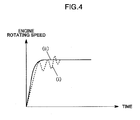
Figure 4 is a graph showing a change of the engine rotating speed in accelerating at a maximum rate; -
Figure 5 is a graph showing an effect of decrease of engine rotating speed in limiting an upper driving speed; -
Figure 6 is a block diagram showing a driving system and a control system in the second embodiment of the present invention; -
Figure 7 is a graph showing a relationship between an engine rotating speed and a set value for pump displacement; and -
Figure 8 is a flow chart for explaining an operation flow of the second embodiment of the present invention. -
Figure 1 shows a driving system and a control system of the first embodiment. InFig.1 , anengine 1 drives a variable displacementhydraulic pump 2. A variable displacementhydraulic motor 3 is driven by discharged oil of thehydraulic pump 2. Thehydraulic pump 2 and thehydraulic motor 3 are connected each other withpipe lines hydraulic motor 3 is transmitted towheels 7 via anaxel 6. Apower divider 8 divides a power of theengine 1 into powers for thehydraulic pump 2, for an auxiliary pump 9 and for acooling fan 10. - An acceleration inputting means 11 outputs to the engine 1 a signal showing the amount of accelerator manipulation. In this embodiment, the acceleration inputting means 11 is an accelerator pedal. The signal from the acceleration inputting means 11 is inputted to an
engine control portion 13 of a control means 12. Theengine 1 rotates by conducting fuel injection at an accelerator opening degree corresponding to the signal. An engine rotation detecting means 15 detects a rotation number of the engine, and a driving speed detecting means 16 detects a driving speed. The engine rotation number and the driving speed, which are detected by both detectingmeans pump control portion 14 of the control means 12. Thepump control portion 14 selects a function deciding a set value for pump displacement, based on the detected engine rotation number and the detected driving speed. Based on the set value for pump displacement which is calculated with the function, thepump control portion 14 controls the displacement of thehydraulic pump 2. - This point is described in detail hereinafter. Conventionally, when a HST type vehicle drives at a constant speed, the displacement of the
hydraulic pump 2 is controlled by the set value for pump displacement. The set value is calculated by multiplying the engine rotating speed by the determined function. Accordingly, the set value for pump displacement is determined, based on only the engine rotating speed. As shown with the mark "a" inFig.2 , in the driving speed "V", the set value for pump displacement is determined by multiplying the engine rotating speed by the function "f1". - In this embodiment, the function regarding the engine rotating speed is varied in accordance with the driving speed. Accordingly, in a high driving speed zone where the driving speed is more than the set value "V", as shown with the mark "b" in
Fig. 2 , the set value for pump displacement is determined by a function "f2" which is set so as to make the set value for pump displacement more than that of the function "f1". On the other hand, in a low driving speed zone where driving speed is less than the set value "V", as shown with the mark "c" inFig.2 , the set value for pump displacement is determined by a function "f3" which is set so as to make the set value for pump displacement less than that of the function "f1". In other words, the set value for pump displacement in the high driving speed zone is larger than that in the low driving speed zone. - In this embodiment, comparing with the conventional technology whose function can not be changed, it is possible to decrease the engine rotating speed which can obtain the same amount of discharged oil from the pump in the high driving speed zone. For this reason, as shown in
Fig.3 , it is possible to improve fuel consumption rate in response to the amount of engine rotating speed decreasing. As the amount of discharged oil from the pump corresponds to the driving speed, it is possible to improve fuel efficiency in a high speed vehicle like a wheel crane which often drives at a high speed. - In addition to this merit, it is possible to improve efficiency of the pump because of increasing the pump displacement. Moreover, because the rotating speeds of the auxiliary pump 9 and the cooling
fan 10 which are driven by thepower divider 8 also goes down in response to the decrease of the engine rotating speed, energy loss occurred in these devices is also decreased. For these reasons, the fuel efficiency becomes much better. - On the other hand, in the control as shown with the mark "b" in
Fig.2 , the changing rate of the set value for pump displacement in response to the engine rotating speed is relatively large. In the case that only this control is executed, a disadvantage occurs so that the engine rotating speed becomes instable at the start stage. As shown with the mark (i) inFig.4 , in accelerating from a stopping condition to a full speed driving condition, the engine rotating speed at the start stage becomes instable. - In this first embodiment, in the low speed zone, as shown with the mark "c" in
Fig.2 , a control is executed so as to decrease the changing rate of the set value for pump displacement in response to the engine rotating speed. For this reason, as shown with the mark (ii) inFig.4 , the engine rotating speed at the start stage becomes stable. - In the case that the engine rotating speed is limited so that the driving speed is less than a certain value, in the first embodiment, in addition to the control limiting the engine rotating speed, the above-mentioned control changing the function is executed. For this reason, as shown in
Fig.5 , because it is possible to decrease the engine rotating speed to a greater extent, the fuel efficiency is more improved in case of driving at a predetermined speed limit. - By the way, in this embodiment, it is preferable that, setting an upper limit in a high speed zone and a lower limit in a low speed zone, the function keeps constant regardless of the change of driving speed in the zones where the driving speed is more than the upper limit or it is less than the lower limit. In this case, it is possible that the pump displacement keeps within a constant range both in the high and low speed zones. Accordingly, it is possible to remove the disadvantage that the accelerating performance becomes worse by reason of too little pump displacement in the low speed zone. Moreover, it is also possible to remove the disadvantage that shortage of power or deterioration of engine efficiency by reason of too little engine rotating speed in the high speed zone makes fuel efficiency worse.
- Only the differences from the first embodiment are explained hereinafter. In the second embodiment, not only in addition to the improvement of the fuel efficiency in the high speed zone, but also in the low speed zone where the amount of manipulated accelerator is a little, the fuel efficiency is improved by decreasing the engine rotating speed. The amount of manipulated accelerator corresponds to a load occurred in driving.
- As shown in
Fig.6 , a manipulated acceleratoramount detecting means 17 is added as another detecting means. The manipulated acceleratoramount detecting means 17 detects the amount of manipulated accelerator by a signal from the acceleration inputting means 11. The amount of manipulated accelerator is transmitted to thepump control portion 14 together with the engine rotating speed and the driving speed. Thepump control portion 14 determines the set value for pump displacement based on these signals. - This point is explained in detail hereinafter. As shown with the mark "a" in
Fig.7 , in a set value "X" for manipulated accelerator amount, the set value for pump displacement is determined by a function "g1" in response to the engine rotating speed. In the second embodiment, the function varies in accordance with the manipulated accelerator amount. Accordingly, in a little manipulated accelerator zone where the manipulated accelerator amount is less than the set value "X", as shown with the mark "b" inFig.7 , the set value for pump displacement is determined by a function "g2" which is set so as to become larger than the set value for pump displacement determined by the function"g1". On the other hand, within a large manipulated accelerator zone where the manipulated accelerator amount is less than X1 and more than X, denoted by "X-X1" inFig.8 , the set value for pump displacement is determined by a function "g3" which is set so as to become smaller than the set value for pump displacement determined by the function "g1". Moreover, in an extra large manipulated accelerator zone where the manipulated accelerator amount is not less than X1, the control which uses the function corresponding to the driving speed as explained above as the first embodiment is executed as being in a high speed zone. - This control is explained in detail hereinafter by the flow chart
Fig.8 , InFig.8 , in a step S1, the detected manipulated accelerator amount and the set value "X" are compared each other. In the case that the accelerator amount is not more than "X", a step S2 is executed. On the other hand, in the case that the accelerator amount is within the range of "X ∼X1", a step S3 is executed. In the step S2, the set value for pump displacement is determined by the function "g2". On the other hand, in the step S3, the set value for pump displacement is determined by the function "g3". - In the case that the accelerator amount is not less than "X1", the processes explained in the first embodiment are executed as being in the high speed zone. That is to say, in a step S4, the detected driving speed and the set value "V" are compared each other. In the case that the driving speed is not less than "V", the set value for pump displacement is determined by the function "f2" in a step S5. In the case that the driving speed is less than "V", the set value for pump displacement is determined by the function "f3" in a step S6.
- In a step S7, the set value for pump displacement is outputted, which is determined in one of the above steps S2, S5, S6.
- In this second embodiment, it is possible to decrease the engine rotating speed by increasing the pump displacement even in the little manipulated accelerator zone. Accordingly, even in the driving condition where energy and load necessary for driving is low, for example, in driving at low speed or in driving on an uphill road, the fuel efficiency is improved.
- Here, also in the second embodiment, as in the first embodiment, setting a lower limit in the little manipulated accelerator zone, it is possible to keep the function constant regardless of the manipulated accelerator amount in an extra little manipulated accelerator zone where the amount is less than the lower limit. In this case, since the set value for pump displacement can be kept within a certain range, in the extra little manipulated accelerator zone, it is possible to remove a disadvantage of engine stopping which is caused by reason of too much pump displacement.
- In a hydraulic driven vehicle of the present invention, an
engine 1 drives a variable displacementhydraulic pump 2. Ahydraulic motor 3 is driven by hydraulic oil supplied from thehydraulic pump 2. A rotation number of theengine 1 is detected by an engine rotatingspeed detecting means 15, and a driving speed is detected by a drivingspeed detecting means 16. A control means 12 determines a set value for pump displacement of thehydraulic pump 2 by calculating with a function. The function is set so as to make the set value in a high speed zone larger than the set value in a low speed zone. Accordingly, in a HST type hydraulic driven vehicle, fuel efficiency is improved in the high speed zone.
Claims (5)
- A control apparatus of a hydraulic driven vehicle, comprising:an engine (1);a variable displacement hydraulic pump (2) driven by said engine (1);a hydraulic motor (3) driven by hydraulic oil supplied from said hydraulic pump (2);a driving speed detecting means (16) for detecting a driving speed of the hydraulic driven vehicle; andan engine rotating speed detecting means (15) for detecting a rotation number of said engine (1);characterized in thatthe control apparatus further comprising:a control means (12) for controlling a displacement of said variable displacement hydraulic pump (2) based on a set value for pump displacement which is determined by a function and an engine rotating speed detected by said engine rotating speed detecting means (15), the function making the set value in a high speed zone larger than the set value in a low speed, the high and low speed zones determined by the driving speed detected by said driving speed detecting means (16).
- The control apparatus according to claim 1, wherein
said control means (12) keeps the function constant regardless of a change of the driving speed, either in the high speed zone where the driving speed is higher than an upper limit for driving speed or in the low speed zone where the driving speed is lower than a lower limit for driving speed, or both in the zones. - The control apparatus according to claim 1 or 2, wherein
said control means (12) controls said engine (1) so as to keep the driving speed lower than the upper limit. - The control apparatus according to any one of claims 1 through 3, wherein
the function of said control means (12) regulates so that the set value for pump displacement in a little manipulated accelerator zone is larger than the set value for pump displacement in a large manipulated acceleration zone, and
the little manipulated acceleration zone where a manipulated acceleration amount detected by a manipulated accelerator amount detecting means (17) and inputted by an acceleration inputting means (11) is not more than a set value for manipulated accelerator amount, and
the large manipulated acceleration zone where the manipulated accelerator amount is more than the set value for manipulated accelerator amount. - The control apparatus according to claim 4, wherein
said control means (12) keeps the function constant regardless of a change of manipulated accelerator amount in an extra little manipulated accelerator zone where the manipulated accelerator amount is less than a lower limit of the little manipulated accelerator zone.
Applications Claiming Priority (1)
| Application Number | Priority Date | Filing Date | Title |
|---|---|---|---|
| JP2008126367A JP4589979B2 (en) | 2008-05-13 | 2008-05-13 | Control device for hydraulic traveling vehicle |
Publications (3)
| Publication Number | Publication Date |
|---|---|
| EP2119943A2 true EP2119943A2 (en) | 2009-11-18 |
| EP2119943A3 EP2119943A3 (en) | 2010-05-05 |
| EP2119943B1 EP2119943B1 (en) | 2011-10-12 |
Family
ID=40886470
Family Applications (1)
| Application Number | Title | Priority Date | Filing Date |
|---|---|---|---|
| EP09160017A Not-in-force EP2119943B1 (en) | 2008-05-13 | 2009-05-12 | Control apparatus for hydraulic driving vehicle |
Country Status (3)
| Country | Link |
|---|---|
| EP (1) | EP2119943B1 (en) |
| JP (1) | JP4589979B2 (en) |
| AT (1) | ATE528554T1 (en) |
Cited By (8)
| Publication number | Priority date | Publication date | Assignee | Title |
|---|---|---|---|---|
| CN102101436A (en) * | 2011-01-26 | 2011-06-22 | 江苏嘉捷特种车辆制造有限公司 | Walking transmission system for airport equipment |
| CN102126429A (en) * | 2011-01-26 | 2011-07-20 | 江苏嘉捷特种车辆制造有限公司 | Special self-propelled chassis for airport |
| CN102555805A (en) * | 2011-12-15 | 2012-07-11 | 中联重科股份有限公司 | Motor vehicle, control system of rear vehicle part of motor vehicle and vehicle speed control method |
| WO2014210260A1 (en) * | 2013-06-27 | 2014-12-31 | Robert Bosch Gmbh | Speed-based hydraulic pump control system and method for noise reduction in hybrid vehicles |
| IT202000016066A1 (en) * | 2020-07-02 | 2022-01-02 | Cnh Ind Italia Spa | CONTROL SYSTEM OF A HYDRAULIC TRANSMISSION OF A WORK OR AGRICULTURAL MACHINE |
| IT202000023857A1 (en) * | 2020-10-09 | 2022-04-09 | Cnh Ind Italia Spa | METHOD AND SYSTEM OF BRAKING AN AGRICULTURAL OR WORK VEHICLE EQUIPPED WITH HYDRAULIC TRANSMISSION |
| IT202200013528A1 (en) * | 2022-06-27 | 2023-12-27 | Cnh Ind Italia Spa | CONTROL SYSTEM OF A HYDRAULIC TRANSMISSION OF A WORK OR AGRICULTURAL MACHINE |
| EP4375104A1 (en) | 2022-11-23 | 2024-05-29 | CNH Industrial Italia S.p.A. | Method and system for controlling a propulsion system of a work or agricultural vehicle |
Families Citing this family (2)
| Publication number | Priority date | Publication date | Assignee | Title |
|---|---|---|---|---|
| JP4978688B2 (en) * | 2009-12-22 | 2012-07-18 | コベルコクレーン株式会社 | Travel speed control system |
| JP5892672B2 (en) * | 2015-02-09 | 2016-03-23 | サミー株式会社 | Slot machine |
Citations (2)
| Publication number | Priority date | Publication date | Assignee | Title |
|---|---|---|---|---|
| US6343470B1 (en) | 1999-09-05 | 2002-02-05 | Honda Giken Kogyo Kabushiki Kaisha | Control method for hydrostatic type continuously variable transmission |
| EP1609659A2 (en) | 2004-06-22 | 2005-12-28 | Kanzaki Kokyukoki Mfg. Co., Ltd. | Speed control method for working vehicle |
Family Cites Families (3)
| Publication number | Priority date | Publication date | Assignee | Title |
|---|---|---|---|---|
| US5503534A (en) * | 1995-03-16 | 1996-04-02 | Eaton Corporation | Automotive drive control for hydrostatic transmission |
| JPH10306874A (en) * | 1997-05-06 | 1998-11-17 | Mitsubishi Heavy Ind Ltd | Hydraulic type vehicle |
| US6852064B2 (en) * | 2002-07-18 | 2005-02-08 | Sauer-Danfoss, Inc. | Hydromechanical transmission electronic control system for high speed vehicles |
-
2008
- 2008-05-13 JP JP2008126367A patent/JP4589979B2/en active Active
-
2009
- 2009-05-12 EP EP09160017A patent/EP2119943B1/en not_active Not-in-force
- 2009-05-12 AT AT09160017T patent/ATE528554T1/en not_active IP Right Cessation
Patent Citations (2)
| Publication number | Priority date | Publication date | Assignee | Title |
|---|---|---|---|---|
| US6343470B1 (en) | 1999-09-05 | 2002-02-05 | Honda Giken Kogyo Kabushiki Kaisha | Control method for hydrostatic type continuously variable transmission |
| EP1609659A2 (en) | 2004-06-22 | 2005-12-28 | Kanzaki Kokyukoki Mfg. Co., Ltd. | Speed control method for working vehicle |
Cited By (13)
| Publication number | Priority date | Publication date | Assignee | Title |
|---|---|---|---|---|
| CN102101436A (en) * | 2011-01-26 | 2011-06-22 | 江苏嘉捷特种车辆制造有限公司 | Walking transmission system for airport equipment |
| CN102126429A (en) * | 2011-01-26 | 2011-07-20 | 江苏嘉捷特种车辆制造有限公司 | Special self-propelled chassis for airport |
| CN102555805A (en) * | 2011-12-15 | 2012-07-11 | 中联重科股份有限公司 | Motor vehicle, control system of rear vehicle part of motor vehicle and vehicle speed control method |
| CN102555805B (en) * | 2011-12-15 | 2015-04-01 | 中联重科股份有限公司 | Motor vehicle, control system of rear vehicle part of motor vehicle and vehicle speed control method |
| WO2014210260A1 (en) * | 2013-06-27 | 2014-12-31 | Robert Bosch Gmbh | Speed-based hydraulic pump control system and method for noise reduction in hybrid vehicles |
| US8960358B2 (en) | 2013-06-27 | 2015-02-24 | Robert Bosch Gmbh | Speed-based hydraulic pump control system and method for noise reduction in hybrid vehicles |
| IT202000016066A1 (en) * | 2020-07-02 | 2022-01-02 | Cnh Ind Italia Spa | CONTROL SYSTEM OF A HYDRAULIC TRANSMISSION OF A WORK OR AGRICULTURAL MACHINE |
| EP3933121A1 (en) * | 2020-07-02 | 2022-01-05 | CNH Industrial Italia S.p.A. | System for controlling a propulsion system of a work or agricultural vehicle |
| IT202000023857A1 (en) * | 2020-10-09 | 2022-04-09 | Cnh Ind Italia Spa | METHOD AND SYSTEM OF BRAKING AN AGRICULTURAL OR WORK VEHICLE EQUIPPED WITH HYDRAULIC TRANSMISSION |
| EP3981661A1 (en) * | 2020-10-09 | 2022-04-13 | CNH Industrial Italia S.p.A. | Braking method and system of an agricultural or work vehicle equipped with a hydraulic transmission |
| IT202200013528A1 (en) * | 2022-06-27 | 2023-12-27 | Cnh Ind Italia Spa | CONTROL SYSTEM OF A HYDRAULIC TRANSMISSION OF A WORK OR AGRICULTURAL MACHINE |
| EP4299952A1 (en) * | 2022-06-27 | 2024-01-03 | CNH Industrial Italia S.p.A. | Control system of a hydraulic transmission of a work or agricultural vehicle |
| EP4375104A1 (en) | 2022-11-23 | 2024-05-29 | CNH Industrial Italia S.p.A. | Method and system for controlling a propulsion system of a work or agricultural vehicle |
Also Published As
| Publication number | Publication date |
|---|---|
| ATE528554T1 (en) | 2011-10-15 |
| EP2119943A3 (en) | 2010-05-05 |
| JP4589979B2 (en) | 2010-12-01 |
| JP2009275784A (en) | 2009-11-26 |
| EP2119943B1 (en) | 2011-10-12 |
Similar Documents
| Publication | Publication Date | Title |
|---|---|---|
| EP2119943A2 (en) | Control apparatus for hydraulic driving vehicle | |
| EP2418403B1 (en) | Construction vehicle | |
| EP2119942B1 (en) | Clutch control device for hydraulically driven vehicle | |
| CN101558243B (en) | Engine load control device of work vehicle | |
| WO2013136536A1 (en) | Work vehicle and method for controlling work vehicle | |
| KR100325496B1 (en) | How to adjust the transmission ratio of the transmission of a car | |
| JP4664246B2 (en) | Engine control device for work vehicle | |
| KR20070046853A (en) | Load control device for engine of work vehicle | |
| WO2005014989A1 (en) | Control device for working vehicle | |
| JP5113946B1 (en) | Work vehicle and control method of work vehicle | |
| JP2008144969A (en) | Transmission operation method | |
| KR20060086377A (en) | Load controller for engine of work vehicle | |
| EP3553297B1 (en) | Work vehicle and method for controlling work vehicle | |
| KR101752503B1 (en) | Method for controlling hydraulic pump of wheel loader | |
| EP3553349B1 (en) | Work vehicle and method for controlling work vehicle | |
| JP2004144254A (en) | Hydraulic-driven vehicle | |
| US7022044B2 (en) | Drive train for powering a mobile vehicle | |
| EP3147543B1 (en) | Transmission system having efficiency-based speed control | |
| EP2123533B1 (en) | Control apparatus of hydraulic driven vehicle | |
| WO2006006600A1 (en) | Control device for hydraulic pump for working machine of working vehicle | |
| CN106687348B (en) | Powertrain system with efficiency-based speed control | |
| US9945101B2 (en) | Work vehicle | |
| JP2001354051A (en) | Driving force controller for vehicle | |
| CN108622098B (en) | Integrated control method for engine and transmission | |
| JP2011169351A (en) | Hst type construction vehicle |
Legal Events
| Date | Code | Title | Description |
|---|---|---|---|
| PUAI | Public reference made under article 153(3) epc to a published international application that has entered the european phase |
Free format text: ORIGINAL CODE: 0009012 |
|
| AK | Designated contracting states |
Kind code of ref document: A2 Designated state(s): AT BE BG CH CY CZ DE DK EE ES FI FR GB GR HR HU IE IS IT LI LT LU LV MC MK MT NL NO PL PT RO SE SI SK TR |
|
| PUAL | Search report despatched |
Free format text: ORIGINAL CODE: 0009013 |
|
| AK | Designated contracting states |
Kind code of ref document: A3 Designated state(s): AT BE BG CH CY CZ DE DK EE ES FI FR GB GR HR HU IE IS IT LI LT LU LV MC MK MT NL NO PL PT RO SE SI SK TR |
|
| AX | Request for extension of the european patent |
Extension state: AL BA RS |
|
| 17P | Request for examination filed |
Effective date: 20101018 |
|
| GRAP | Despatch of communication of intention to grant a patent |
Free format text: ORIGINAL CODE: EPIDOSNIGR1 |
|
| RIC1 | Information provided on ipc code assigned before grant |
Ipc: B60W 10/06 20060101ALI20110329BHEP Ipc: F16H 59/42 20060101ALN20110329BHEP Ipc: B60W 30/18 20060101ALI20110329BHEP Ipc: F16H 59/36 20060101ALN20110329BHEP Ipc: F16H 59/44 20060101ALN20110329BHEP Ipc: F16H 61/42 20100101ALI20110329BHEP Ipc: F16H 61/46 20100101AFI20110329BHEP |
|
| GRAS | Grant fee paid |
Free format text: ORIGINAL CODE: EPIDOSNIGR3 |
|
| GRAA | (expected) grant |
Free format text: ORIGINAL CODE: 0009210 |
|
| AK | Designated contracting states |
Kind code of ref document: B1 Designated state(s): AT BE BG CH CY CZ DE DK EE ES FI FR GB GR HR HU IE IS IT LI LT LU LV MC MK MT NL NO PL PT RO SE SI SK TR |
|
| REG | Reference to a national code |
Ref country code: GB Ref legal event code: FG4D |
|
| REG | Reference to a national code |
Ref country code: CH Ref legal event code: EP |
|
| REG | Reference to a national code |
Ref country code: IE Ref legal event code: FG4D |
|
| REG | Reference to a national code |
Ref country code: DE Ref legal event code: R096 Ref document number: 602009003000 Country of ref document: DE Effective date: 20111208 |
|
| REG | Reference to a national code |
Ref country code: NL Ref legal event code: VDEP Effective date: 20111012 |
|
| LTIE | Lt: invalidation of european patent or patent extension |
Effective date: 20111012 |
|
| REG | Reference to a national code |
Ref country code: AT Ref legal event code: MK05 Ref document number: 528554 Country of ref document: AT Kind code of ref document: T Effective date: 20111012 |
|
| PG25 | Lapsed in a contracting state [announced via postgrant information from national office to epo] |
Ref country code: NO Free format text: LAPSE BECAUSE OF FAILURE TO SUBMIT A TRANSLATION OF THE DESCRIPTION OR TO PAY THE FEE WITHIN THE PRESCRIBED TIME-LIMIT Effective date: 20120112 Ref country code: BE Free format text: LAPSE BECAUSE OF FAILURE TO SUBMIT A TRANSLATION OF THE DESCRIPTION OR TO PAY THE FEE WITHIN THE PRESCRIBED TIME-LIMIT Effective date: 20111012 Ref country code: IS Free format text: LAPSE BECAUSE OF FAILURE TO SUBMIT A TRANSLATION OF THE DESCRIPTION OR TO PAY THE FEE WITHIN THE PRESCRIBED TIME-LIMIT Effective date: 20120212 Ref country code: LT Free format text: LAPSE BECAUSE OF FAILURE TO SUBMIT A TRANSLATION OF THE DESCRIPTION OR TO PAY THE FEE WITHIN THE PRESCRIBED TIME-LIMIT Effective date: 20111012 |
|
| PG25 | Lapsed in a contracting state [announced via postgrant information from national office to epo] |
Ref country code: PT Free format text: LAPSE BECAUSE OF FAILURE TO SUBMIT A TRANSLATION OF THE DESCRIPTION OR TO PAY THE FEE WITHIN THE PRESCRIBED TIME-LIMIT Effective date: 20120213 Ref country code: NL Free format text: LAPSE BECAUSE OF FAILURE TO SUBMIT A TRANSLATION OF THE DESCRIPTION OR TO PAY THE FEE WITHIN THE PRESCRIBED TIME-LIMIT Effective date: 20111012 Ref country code: SI Free format text: LAPSE BECAUSE OF FAILURE TO SUBMIT A TRANSLATION OF THE DESCRIPTION OR TO PAY THE FEE WITHIN THE PRESCRIBED TIME-LIMIT Effective date: 20111012 Ref country code: GR Free format text: LAPSE BECAUSE OF FAILURE TO SUBMIT A TRANSLATION OF THE DESCRIPTION OR TO PAY THE FEE WITHIN THE PRESCRIBED TIME-LIMIT Effective date: 20120113 Ref country code: HR Free format text: LAPSE BECAUSE OF FAILURE TO SUBMIT A TRANSLATION OF THE DESCRIPTION OR TO PAY THE FEE WITHIN THE PRESCRIBED TIME-LIMIT Effective date: 20111012 Ref country code: SE Free format text: LAPSE BECAUSE OF FAILURE TO SUBMIT A TRANSLATION OF THE DESCRIPTION OR TO PAY THE FEE WITHIN THE PRESCRIBED TIME-LIMIT Effective date: 20111012 Ref country code: LV Free format text: LAPSE BECAUSE OF FAILURE TO SUBMIT A TRANSLATION OF THE DESCRIPTION OR TO PAY THE FEE WITHIN THE PRESCRIBED TIME-LIMIT Effective date: 20111012 |
|
| PG25 | Lapsed in a contracting state [announced via postgrant information from national office to epo] |
Ref country code: CY Free format text: LAPSE BECAUSE OF FAILURE TO SUBMIT A TRANSLATION OF THE DESCRIPTION OR TO PAY THE FEE WITHIN THE PRESCRIBED TIME-LIMIT Effective date: 20111012 |
|
| PG25 | Lapsed in a contracting state [announced via postgrant information from national office to epo] |
Ref country code: EE Free format text: LAPSE BECAUSE OF FAILURE TO SUBMIT A TRANSLATION OF THE DESCRIPTION OR TO PAY THE FEE WITHIN THE PRESCRIBED TIME-LIMIT Effective date: 20111012 Ref country code: BG Free format text: LAPSE BECAUSE OF FAILURE TO SUBMIT A TRANSLATION OF THE DESCRIPTION OR TO PAY THE FEE WITHIN THE PRESCRIBED TIME-LIMIT Effective date: 20120112 Ref country code: DK Free format text: LAPSE BECAUSE OF FAILURE TO SUBMIT A TRANSLATION OF THE DESCRIPTION OR TO PAY THE FEE WITHIN THE PRESCRIBED TIME-LIMIT Effective date: 20111012 Ref country code: SK Free format text: LAPSE BECAUSE OF FAILURE TO SUBMIT A TRANSLATION OF THE DESCRIPTION OR TO PAY THE FEE WITHIN THE PRESCRIBED TIME-LIMIT Effective date: 20111012 Ref country code: CZ Free format text: LAPSE BECAUSE OF FAILURE TO SUBMIT A TRANSLATION OF THE DESCRIPTION OR TO PAY THE FEE WITHIN THE PRESCRIBED TIME-LIMIT Effective date: 20111012 |
|
| PLBE | No opposition filed within time limit |
Free format text: ORIGINAL CODE: 0009261 |
|
| STAA | Information on the status of an ep patent application or granted ep patent |
Free format text: STATUS: NO OPPOSITION FILED WITHIN TIME LIMIT |
|
| PG25 | Lapsed in a contracting state [announced via postgrant information from national office to epo] |
Ref country code: IT Free format text: LAPSE BECAUSE OF FAILURE TO SUBMIT A TRANSLATION OF THE DESCRIPTION OR TO PAY THE FEE WITHIN THE PRESCRIBED TIME-LIMIT Effective date: 20111012 Ref country code: RO Free format text: LAPSE BECAUSE OF FAILURE TO SUBMIT A TRANSLATION OF THE DESCRIPTION OR TO PAY THE FEE WITHIN THE PRESCRIBED TIME-LIMIT Effective date: 20111012 Ref country code: PL Free format text: LAPSE BECAUSE OF FAILURE TO SUBMIT A TRANSLATION OF THE DESCRIPTION OR TO PAY THE FEE WITHIN THE PRESCRIBED TIME-LIMIT Effective date: 20111012 |
|
| 26N | No opposition filed |
Effective date: 20120713 |
|
| REG | Reference to a national code |
Ref country code: DE Ref legal event code: R097 Ref document number: 602009003000 Country of ref document: DE Effective date: 20120713 |
|
| PG25 | Lapsed in a contracting state [announced via postgrant information from national office to epo] |
Ref country code: MC Free format text: LAPSE BECAUSE OF NON-PAYMENT OF DUE FEES Effective date: 20120531 |
|
| PG25 | Lapsed in a contracting state [announced via postgrant information from national office to epo] |
Ref country code: AT Free format text: LAPSE BECAUSE OF FAILURE TO SUBMIT A TRANSLATION OF THE DESCRIPTION OR TO PAY THE FEE WITHIN THE PRESCRIBED TIME-LIMIT Effective date: 20111012 |
|
| REG | Reference to a national code |
Ref country code: IE Ref legal event code: MM4A |
|
| PG25 | Lapsed in a contracting state [announced via postgrant information from national office to epo] |
Ref country code: MK Free format text: LAPSE BECAUSE OF FAILURE TO SUBMIT A TRANSLATION OF THE DESCRIPTION OR TO PAY THE FEE WITHIN THE PRESCRIBED TIME-LIMIT Effective date: 20111012 |
|
| REG | Reference to a national code |
Ref country code: FR Ref legal event code: ST Effective date: 20130131 |
|
| PG25 | Lapsed in a contracting state [announced via postgrant information from national office to epo] |
Ref country code: IE Free format text: LAPSE BECAUSE OF NON-PAYMENT OF DUE FEES Effective date: 20120512 Ref country code: FR Free format text: LAPSE BECAUSE OF NON-PAYMENT OF DUE FEES Effective date: 20120531 Ref country code: ES Free format text: LAPSE BECAUSE OF FAILURE TO SUBMIT A TRANSLATION OF THE DESCRIPTION OR TO PAY THE FEE WITHIN THE PRESCRIBED TIME-LIMIT Effective date: 20120123 |
|
| PG25 | Lapsed in a contracting state [announced via postgrant information from national office to epo] |
Ref country code: FI Free format text: LAPSE BECAUSE OF FAILURE TO SUBMIT A TRANSLATION OF THE DESCRIPTION OR TO PAY THE FEE WITHIN THE PRESCRIBED TIME-LIMIT Effective date: 20111012 |
|
| PG25 | Lapsed in a contracting state [announced via postgrant information from national office to epo] |
Ref country code: MT Free format text: LAPSE BECAUSE OF FAILURE TO SUBMIT A TRANSLATION OF THE DESCRIPTION OR TO PAY THE FEE WITHIN THE PRESCRIBED TIME-LIMIT Effective date: 20111012 |
|
| REG | Reference to a national code |
Ref country code: CH Ref legal event code: PL |
|
| GBPC | Gb: european patent ceased through non-payment of renewal fee |
Effective date: 20130512 |
|
| PG25 | Lapsed in a contracting state [announced via postgrant information from national office to epo] |
Ref country code: LI Free format text: LAPSE BECAUSE OF NON-PAYMENT OF DUE FEES Effective date: 20130531 Ref country code: CH Free format text: LAPSE BECAUSE OF NON-PAYMENT OF DUE FEES Effective date: 20130531 |
|
| PG25 | Lapsed in a contracting state [announced via postgrant information from national office to epo] |
Ref country code: TR Free format text: LAPSE BECAUSE OF FAILURE TO SUBMIT A TRANSLATION OF THE DESCRIPTION OR TO PAY THE FEE WITHIN THE PRESCRIBED TIME-LIMIT Effective date: 20111012 Ref country code: GB Free format text: LAPSE BECAUSE OF NON-PAYMENT OF DUE FEES Effective date: 20130512 |
|
| PG25 | Lapsed in a contracting state [announced via postgrant information from national office to epo] |
Ref country code: LU Free format text: LAPSE BECAUSE OF NON-PAYMENT OF DUE FEES Effective date: 20120512 |
|
| PG25 | Lapsed in a contracting state [announced via postgrant information from national office to epo] |
Ref country code: HU Free format text: LAPSE BECAUSE OF FAILURE TO SUBMIT A TRANSLATION OF THE DESCRIPTION OR TO PAY THE FEE WITHIN THE PRESCRIBED TIME-LIMIT Effective date: 20090512 |
|
| PGFP | Annual fee paid to national office [announced via postgrant information from national office to epo] |
Ref country code: DE Payment date: 20220329 Year of fee payment: 14 |
|
| REG | Reference to a national code |
Ref country code: DE Ref legal event code: R119 Ref document number: 602009003000 Country of ref document: DE |
|
| PG25 | Lapsed in a contracting state [announced via postgrant information from national office to epo] |
Ref country code: DE Free format text: LAPSE BECAUSE OF NON-PAYMENT OF DUE FEES Effective date: 20231201 |