EP2119923A1 - Rolling bearing device and electric power generation device - Google Patents
Rolling bearing device and electric power generation device Download PDFInfo
- Publication number
- EP2119923A1 EP2119923A1 EP08710908A EP08710908A EP2119923A1 EP 2119923 A1 EP2119923 A1 EP 2119923A1 EP 08710908 A EP08710908 A EP 08710908A EP 08710908 A EP08710908 A EP 08710908A EP 2119923 A1 EP2119923 A1 EP 2119923A1
- Authority
- EP
- European Patent Office
- Prior art keywords
- rolling bearing
- damper member
- housing
- bearing device
- rotating shaft
- Prior art date
- Legal status (The legal status is an assumption and is not a legal conclusion. Google has not performed a legal analysis and makes no representation as to the accuracy of the status listed.)
- Withdrawn
Links
- 238000005096 rolling process Methods 0.000 title claims abstract description 61
- 238000010248 power generation Methods 0.000 title 1
- 239000002184 metal Substances 0.000 claims abstract description 16
- 239000000314 lubricant Substances 0.000 claims description 4
- 230000005489 elastic deformation Effects 0.000 description 8
- 238000013016 damping Methods 0.000 description 6
- 230000000052 comparative effect Effects 0.000 description 5
- 239000000463 material Substances 0.000 description 5
- RTZKZFJDLAIYFH-UHFFFAOYSA-N Diethyl ether Chemical compound CCOCC RTZKZFJDLAIYFH-UHFFFAOYSA-N 0.000 description 4
- 239000004519 grease Substances 0.000 description 4
- 238000011056 performance test Methods 0.000 description 4
- 230000009467 reduction Effects 0.000 description 4
- YCKRFDGAMUMZLT-UHFFFAOYSA-N Fluorine atom Chemical compound [F] YCKRFDGAMUMZLT-UHFFFAOYSA-N 0.000 description 3
- 229920001971 elastomer Polymers 0.000 description 3
- 239000011737 fluorine Substances 0.000 description 3
- 229910052731 fluorine Inorganic materials 0.000 description 3
- 230000007774 longterm Effects 0.000 description 3
- 238000000034 method Methods 0.000 description 3
- 239000003921 oil Substances 0.000 description 3
- 239000005060 rubber Substances 0.000 description 3
- 229920003002 synthetic resin Polymers 0.000 description 3
- 239000000057 synthetic resin Substances 0.000 description 3
- 239000004215 Carbon black (E152) Substances 0.000 description 2
- 230000008602 contraction Effects 0.000 description 2
- 230000007423 decrease Effects 0.000 description 2
- 239000013013 elastic material Substances 0.000 description 2
- 229930195733 hydrocarbon Natural products 0.000 description 2
- 150000002430 hydrocarbons Chemical class 0.000 description 2
- 238000009940 knitting Methods 0.000 description 2
- 239000010687 lubricating oil Substances 0.000 description 2
- 230000001629 suppression Effects 0.000 description 2
- 230000002459 sustained effect Effects 0.000 description 2
- 241000220317 Rosa Species 0.000 description 1
- XUIMIQQOPSSXEZ-UHFFFAOYSA-N Silicon Chemical compound [Si] XUIMIQQOPSSXEZ-UHFFFAOYSA-N 0.000 description 1
- 230000002238 attenuated effect Effects 0.000 description 1
- 239000002199 base oil Substances 0.000 description 1
- 230000003247 decreasing effect Effects 0.000 description 1
- 230000000694 effects Effects 0.000 description 1
- 239000010696 ester oil Substances 0.000 description 1
- 150000002148 esters Chemical class 0.000 description 1
- 230000001788 irregular Effects 0.000 description 1
- 230000035515 penetration Effects 0.000 description 1
- 230000000704 physical effect Effects 0.000 description 1
- 230000001902 propagating effect Effects 0.000 description 1
- 230000000754 repressing effect Effects 0.000 description 1
- 239000010703 silicon Substances 0.000 description 1
- 229910052710 silicon Inorganic materials 0.000 description 1
- 229920002545 silicone oil Polymers 0.000 description 1
- 229910001220 stainless steel Inorganic materials 0.000 description 1
- 239000010935 stainless steel Substances 0.000 description 1
- 239000002562 thickening agent Substances 0.000 description 1
Images



Classifications
-
- F—MECHANICAL ENGINEERING; LIGHTING; HEATING; WEAPONS; BLASTING
- F16—ENGINEERING ELEMENTS AND UNITS; GENERAL MEASURES FOR PRODUCING AND MAINTAINING EFFECTIVE FUNCTIONING OF MACHINES OR INSTALLATIONS; THERMAL INSULATION IN GENERAL
- F16F—SPRINGS; SHOCK-ABSORBERS; MEANS FOR DAMPING VIBRATION
- F16F1/00—Springs
- F16F1/36—Springs made of rubber or other material having high internal friction, e.g. thermoplastic elastomers
- F16F1/362—Springs made of rubber or other material having high internal friction, e.g. thermoplastic elastomers made of steel wool, compressed hair, woven or non-woven textile, or like materials
-
- F—MECHANICAL ENGINEERING; LIGHTING; HEATING; WEAPONS; BLASTING
- F16—ENGINEERING ELEMENTS AND UNITS; GENERAL MEASURES FOR PRODUCING AND MAINTAINING EFFECTIVE FUNCTIONING OF MACHINES OR INSTALLATIONS; THERMAL INSULATION IN GENERAL
- F16C—SHAFTS; FLEXIBLE SHAFTS; ELEMENTS OR CRANKSHAFT MECHANISMS; ROTARY BODIES OTHER THAN GEARING ELEMENTS; BEARINGS
- F16C27/00—Elastic or yielding bearings or bearing supports, for exclusively rotary movement
- F16C27/04—Ball or roller bearings, e.g. with resilient rolling bodies
-
- F—MECHANICAL ENGINEERING; LIGHTING; HEATING; WEAPONS; BLASTING
- F16—ENGINEERING ELEMENTS AND UNITS; GENERAL MEASURES FOR PRODUCING AND MAINTAINING EFFECTIVE FUNCTIONING OF MACHINES OR INSTALLATIONS; THERMAL INSULATION IN GENERAL
- F16C—SHAFTS; FLEXIBLE SHAFTS; ELEMENTS OR CRANKSHAFT MECHANISMS; ROTARY BODIES OTHER THAN GEARING ELEMENTS; BEARINGS
- F16C27/00—Elastic or yielding bearings or bearing supports, for exclusively rotary movement
- F16C27/06—Elastic or yielding bearings or bearing supports, for exclusively rotary movement by means of parts of rubber or like materials
- F16C27/066—Ball or roller bearings
-
- F—MECHANICAL ENGINEERING; LIGHTING; HEATING; WEAPONS; BLASTING
- F16—ENGINEERING ELEMENTS AND UNITS; GENERAL MEASURES FOR PRODUCING AND MAINTAINING EFFECTIVE FUNCTIONING OF MACHINES OR INSTALLATIONS; THERMAL INSULATION IN GENERAL
- F16C—SHAFTS; FLEXIBLE SHAFTS; ELEMENTS OR CRANKSHAFT MECHANISMS; ROTARY BODIES OTHER THAN GEARING ELEMENTS; BEARINGS
- F16C35/00—Rigid support of bearing units; Housings, e.g. caps, covers
- F16C35/04—Rigid support of bearing units; Housings, e.g. caps, covers in the case of ball or roller bearings
- F16C35/06—Mounting or dismounting of ball or roller bearings; Fixing them onto shaft or in housing
- F16C35/07—Fixing them on the shaft or housing with interposition of an element
- F16C35/077—Fixing them on the shaft or housing with interposition of an element between housing and outer race ring
-
- F—MECHANICAL ENGINEERING; LIGHTING; HEATING; WEAPONS; BLASTING
- F16—ENGINEERING ELEMENTS AND UNITS; GENERAL MEASURES FOR PRODUCING AND MAINTAINING EFFECTIVE FUNCTIONING OF MACHINES OR INSTALLATIONS; THERMAL INSULATION IN GENERAL
- F16C—SHAFTS; FLEXIBLE SHAFTS; ELEMENTS OR CRANKSHAFT MECHANISMS; ROTARY BODIES OTHER THAN GEARING ELEMENTS; BEARINGS
- F16C2380/00—Electrical apparatus
- F16C2380/26—Dynamo-electric machines or combinations therewith, e.g. electro-motors and generators
Definitions
- the present invention relates to a rolling bearing device and an electric generator.
- an alternator (electric generator) is equipped with a housing to which a stator is fixed, and a rotating shaft to which a rotor is fixed.
- the rotating shaft is supported by the housing through a rolling bearing. Because the power of an engine is transmitted to the rotating shaft through a drive belt, a high level of vibration caused by high-speed revolutions acts on the rotating shaft through the drive belt, thus inflicting a heavy load upon the rolling bearing device and its overall system.
- a rolling bearing there is a problem that white layer flaking occurs at the outer ring as a ring roller and thus causes a shorter service life.
- the technique uses a vibration damping member intervening between an outer ring and a bearing housing of a rolling bearing in order to attenuate the vibration from a rotating shaft by the vibration damping member.
- the vibration damping member is formed of elastic material such as synthetic resin material and rubber, it is insufficient for repressing the vibration of an apparatus like an alternator used under severe conditions such as high temperature, high-speed revolutions and heavy load, so it is not a sort of a bearing that is durable for a long-term application.
- the present invention was contrived in view of the aforementioned circumstances, and is aimed to provide a rolling bearing device and an electric generator that are adapted to improve their durability by appropriately attenuating vibrations of a shaft by means of an excellent dumping performance and thereby reducing the load imposed on the overall system including the rolling bearing device and its housing.
- a rolling bearing device of the present invention comprises a rolling bearing including: an inner ring and an outer ring disposed so as to be rotatable relatively; and a plurality of rolling elements disposed between the inner ring and the outer ring; the rolling bearing device supports, through the rolling bearing, a shaft rotatable relative to a housing, wherein the rolling bearing device comprises a damper member disposed between the rolling bearing and the housing; and the damper member is formed of metal wire(s) that is(are) knitted.
- an electric generator of the present invention comprises: a stator and a rotor; a housing to which the stator is fixed; a rotating shaft to which the rotor is fixed and an rotational power is transmitted from external; and a rolling bearing that is fixed to the housing and supports the rotating shaft in such a manner that the shaft can rotate unrestrictedly, wherein the electric generator comprises a damper member disposed between the rolling bearing and the housing; and the damper member is formed of metal wire(s) that is(are) knitted.
- the damper member disposed between the rolling bearing and the housing is formed of metal wire(s) that is(are) knitted, it is capable of performing elastic deformation (contraction) over its entire dimensions, attenuating three-dimensionally omnidirectional vibrations, thereby providing a high level of dumping performance.
- the damper member is formed of one or more metal wires, it has high strength and high heat resistance; therefore, even a device with heavy-duty working conditions like an electric generator such as an alternator and the like is capable of serving for a long-term application.
- Gaps are formed between the wire(s), and it is preferable that the gaps are filled with a lubricant. Thereby it is possible to prevent the wires from being worn out by rubbing each other in the course of its elastic deformation.
- Gaps are formed between the wire(s), and it is preferable that the porosity as defined by the ratio of overall volume of the gaps to overall volume of the damper member is set within a range exceeding 50 % and under 70 %. This can result not only in reducing omnidirectional vibrations in a well balanced manner, but also in securing rigidity required to support the rolling bearing.
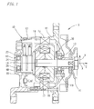
- Fig. 1 is a sectional view of an alternator (electric generator) 9 employing a rolling bearing device according to an embodiment of the present invention.
- the alternator 9 comprises a housing 12 and a rotating shaft 14.
- the housing 12 comprises a front housing 10 and a rear housing 11 conjoined by bolts.
- the rotating shaft 14 is rotatably supported by means of two rolling bearings 13, 13 inside the housing 12.
- a stator 16 comprising a wound coil 15.
- a rotor 18 comprising a wound coil 17.
- To an end of the rotating shaft 14 protruding from the housing 12 is attached a pulley 19 with a built-in fan.
- To the pulley 19 is transmitted a motive power from an engine through a drive belt which is not illustrated.
- the rolling bearing 13 is mounted inside a support tube member 20 formed in the housing 12 at each end of the axial direction.
- the rolling bearing 13 comprises an outer ring 23; an inner ring 24 disposed diametrically inside the outer ring 23; and a number of balls (rolling elements) 25 disposed between the outer ring 23 and the inner ring 24, and it is made such that the outer ring 23 and the inner ring 24 are relatively rotatable.
- On the inner circumferential surface of the inner ring 24 of the rolling bearing 13 is fitted the rotating shaft 14, and between the outer circumferential surface of the outer ring 23 and the inner circumferential surface of the support tube member 20 of the rolling bearing 13, there is disposed a damper member 60 to attenuate vibrations occurring with revolution of the rotating shaft 14.
- the rolling bearing device of the present invention is composed of the rolling bearing 13 and the damper member 60.
- Fig. 2 is a perspective view of the damper member 60, and the damper member 60 is formed in a ring-shape of a generally rectangular cross section having a width w and a thickness t .
- the inner circumferential surface of the damper member 60 is engaged with the outer circumferential surface of the outer ring 23 of the rolling bearing 13, and the outer circumferential surface of the damper member 60 abuts against the inner circumferential surface of the support tube member 20.
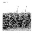
- Fig. 3 is an enlarged view of the portion III of Fig. 2 .
- the damper member 60 is formed of metal wire(s) 64 such as stainless steel as its material. Concretely, one or more metal wires 64 are three-dimensionally knitted while intricately flexed (i.e., one or more wires 64 are gathered, twisted, interlaced and/or intertwined with each other), thereby forming the damper member 60 in a ring-shape as a whole with a generally rectangular cross section.
- the damper member 60 is capable of performing elastic deformation (contraction) generally in a diametrical direction (X-direction (page penetration direction), Y-direction, etc. in Fig. 1 ), and shaft center Z-direction, by means of the wire 64 performing elastic deformation within the range of the gaps, the wires next to each other displacing longitudinally, and so on. Then, the damper member 60 is formed with an external diameter slightly greater than the inside diameter of the support tube member 20, and disposed, as shown in Fig. 1 , between the rolling bearing 13 and the support tube member 20 in a diametrically compressed state by a predetermined interference.
- gaps between wires 64 in the damper member 60 are filled with a lubricant.
- a lubricant lubricating oil or grease can be used.
- lubricating oil for example, either of those from ester, ether, silicon, fluorine and synthetic hydrocarbon type is used.
- grease for example, either of those in which a thickener of lithium-type or urea-type is added to a base oil of those from ester oil, ether oil, silicone oil, fluorine oil or synthetic hydrocarbon oil is used.
- a metal wire 64 for example, one of those having 0.4 mm external diameter is used.
- the ratio (porosity) of the total volume occupied by the gaps to the total volume of the damper member 60 can be made as e.g. 60 %.
- the damper member 60 is produced as follows. First, a ring-shaped intermediate article is formed having external diameter, thickness t and width w slightly greater than, and inside diameter smaller than, those of a finally shaped article. The intermediate article is formed by moderately knitting the metal wire 64 in order to have porosity greater than the porosity (e. g., 60 %) of a finally shaped article. Then the gaps between wires 64 are decreased by compressing the intermediate article using a metallic mold, thus forming a finally shaped article with desired dimensions and porosity.
- vibrations transmitted through the rotating shaft 14 from the drive belt to the rolling bearing 13 are attenuated by the damper member 60, and then transmitted to the housing 12.
- the damper member 60 is capable of performing elastic deformation in diametrical (X-, Y-) and shaft center (Z-) directions, it is capable of attenuating vibrations three dimensionally and omnidirectionally, thereby providing a high level of damping performance.
- vibrational energy of all directions is sustained and can be alleviated by its performance that surpasses simple viscoelasticity.
- vibrations propagating from the rotating shaft 14 to the housing 12 through the rolling bearing 13 are reduced, so that the durability of the rolling bearing 13, the housing 12 and, in turn, the alternator 9 as a whole, can be improved.
- white layer flaking can be suppressed.
- noise can be reduced as a result of decrease of vibrations.
- the damper member 60 is formed using metal wire(s) 64, it can provide robust strength and heat resistance. Accordingly, it does not deteriorate at an early stage even under high vibrations (high load), high temperature working conditions, so that its long-term use is enabled. Also, since the gaps between the wires 64 in the damper member 60 are filled with grease, there is little chance of the wires 64 rubbing each other to be worn out in the course of elastic deformation.
- the elastic modulus (constant of spring) of the damper member 60 can be changed freely by appropriately selecting its porosity, direction of knitting, and external diameter of the wire 64, etc. Further, the elastic modulus can be made different depending on the direction (diametrical direction, axial direction) of elastic deformation. Thus, a damper member 60 according to the required damping characteristics can be produced easily. Moreover, because the geometry of the damper member 60 (outside diameter, inside diameter, width w , thickness t , cross-sectional geometry) can be designed freely, degree of freedom in designing an alternator 9 increases, which allows one to produce optimal alternators 9.
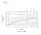
- Fig. 4 and Fig. 5 are graphs showing the test result.
- Fig. 4(a) shows a change in number of revolutions with passage of time
- Fig. 4(b) and Fig. 5 show changes in the vibration values of the housing in X-direction, Y-direction and Z-direction that resulted from the change in number of revolutions expressed in Fig. 4(a) .
- a damper member 60 of 60 % porosity was used, whereas a damper member 60 of 50 % porosity was used in the test shown in Fig. 5 .
- the gaps between wires 64 were filled with fluorine type grease.
- Fig. 6 shows, as a comparative example, the vibration values measured in a test under the same condition as performed in Fig. 4 and Fig. 5 , however on an alternator 9 without a damper member (i.e. in which the rolling bearing 13 was mounted directly to the support tube member 20).
- strength of a damper member 60 decreases when porosity becomes not less than 70 %, so that the rigidity to support the rolling bearing 13 becomes lowered; so, in this respect also, it is thought that using a damper member 60 of 60 % porosity is preferred.
- the porosity of the damper member 60 in order to reduce the vibration values in a well balanced manner omnidirectionally in X-, Y- and Z- directions, and in order to retain the rigidity enough to support the rolling bearing 13, it is preferred to set the porosity of the damper member 60 to fall within the range of over 50 % and under 70 %, and more preferred to fall within 55 % - 65 %.
- the damper member 60 of the present invention consists of one or more metal wires, the vibration suppression effect is sustained even at a high temperature. Consequently, it is superior to conventional damper members that are made from rubbers and/or synthetic resin materials whose vibration suppression effect deteriorates due to change of their physical properties at high temperatures.
- the present invention is adapted for any appropriate design change without being limited to the above-mentioned embodiments.
- material and/or external diameter of the metal wire 64 forming the damper member 60, porosity of the damper member 60, etc. can be changed accordingly.
- the damper member 60 is formed in the shape of a ring; however, it may otherwise be made to have circular arc geometry or block geometry divided in circumferential direction.
- the cross-sectional shape of the damper member 60 may be circular, or polygonal other than quadrangular.
- the rolling bearing 13 may be a roller bearing, not limited to a ball bearing.
- an electric generator may be a DC generator, not limited to an AC electric generator (an alternator).
- the present invention can be applied to other apparatus using a rolling bearing, not limited to an electric generator.
Landscapes
- Engineering & Computer Science (AREA)
- General Engineering & Computer Science (AREA)
- Mechanical Engineering (AREA)
- Textile Engineering (AREA)
- Support Of The Bearing (AREA)
- Rolling Contact Bearings (AREA)
- Motor Or Generator Frames (AREA)
- Vibration Prevention Devices (AREA)
- Springs (AREA)
Abstract
The invention is for the purpose, in a rolling bearing device, of improving its durability by appropriately attenuating vibration of a rotating shaft by means of a high level of dumping performance, and thereby to reduce the load imposed on the rolling bearing and/or the overall system. A rolling bearing device of the present invention comprises a rolling bearing (13) including: an inner ring (24) and an outer ring (23) that are disposed so as to be relatively rotatable; and a plurality of rolling elements (25) disposed between the inner ring (24) and the outer ring (23), in which the rolling bearing (13) supports relative rotation between a shaft (14) and a housing (12). Besides, the rolling bearing device comprises, between the rolling bearing (13) and the housing (12), a damper member (60) formed by one or more metal wires (64) that are knitted.
Description
- The present invention relates to a rolling bearing device and an electric generator.
- In an automobile, an alternator (electric generator) is equipped with a housing to which a stator is fixed, and a rotating shaft to which a rotor is fixed. The rotating shaft is supported by the housing through a rolling bearing. Because the power of an engine is transmitted to the rotating shaft through a drive belt, a high level of vibration caused by high-speed revolutions acts on the rotating shaft through the drive belt, thus inflicting a heavy load upon the rolling bearing device and its overall system. In particular, in a rolling bearing, there is a problem that white layer flaking occurs at the outer ring as a ring roller and thus causes a shorter service life.
- For example, in Japanese Patent Application Publication
JP-A-2005-308 032
However, because the vibration damping member is formed of elastic material such as synthetic resin material and rubber, it is insufficient for repressing the vibration of an apparatus like an alternator used under severe conditions such as high temperature, high-speed revolutions and heavy load, so it is not a sort of a bearing that is durable for a long-term application.
In particular, it is difficult for an elastic material such as synthetic resin materials and rubber to sustain a vibration depression effect under high temperature environments. Therefore, it is substantially difficult to adopt the technique as described in Japanese Patent Application PublicationJP-A-2005-308 032 - The present invention was contrived in view of the aforementioned circumstances, and is aimed to provide a rolling bearing device and an electric generator that are adapted to improve their durability by appropriately attenuating vibrations of a shaft by means of an excellent dumping performance and thereby reducing the load imposed on the overall system including the rolling bearing device and its housing.
- A rolling bearing device of the present invention comprises a rolling bearing including: an inner ring and an outer ring disposed so as to be rotatable relatively; and a plurality of rolling elements disposed between the inner ring and the outer ring; the rolling bearing device supports, through the rolling bearing, a shaft rotatable relative to a housing, wherein the rolling bearing device comprises a damper member disposed between the rolling bearing and the housing; and the damper member is formed of metal wire(s) that is(are) knitted.
- Besides, an electric generator of the present invention comprises: a stator and a rotor; a housing to which the stator is fixed; a rotating shaft to which the rotor is fixed and an rotational power is transmitted from external; and a rolling bearing that is fixed to the housing and supports the rotating shaft in such a manner that the shaft can rotate unrestrictedly, wherein the electric generator comprises a damper member disposed between the rolling bearing and the housing; and the damper member is formed of metal wire(s) that is(are) knitted.
- According to the above-mentioned inventions, since the damper member disposed between the rolling bearing and the housing is formed of metal wire(s) that is(are) knitted, it is capable of performing elastic deformation (contraction) over its entire dimensions, attenuating three-dimensionally omnidirectional vibrations, thereby providing a high level of dumping performance. Thus, it is possible to reduce the load on the rolling bearing and the overall system, and thus to improve their durability.
As for the rolling bearing, this helps in particular to repress white layer peeling. Additionally, because the damper member is formed of one or more metal wires, it has high strength and high heat resistance; therefore, even a device with heavy-duty working conditions like an electric generator such as an alternator and the like is capable of serving for a long-term application. - Gaps are formed between the wire(s), and it is preferable that the gaps are filled with a lubricant. Thereby it is possible to prevent the wires from being worn out by rubbing each other in the course of its elastic deformation.
- Gaps are formed between the wire(s), and it is preferable that the porosity as defined by the ratio of overall volume of the gaps to overall volume of the damper member is set within a range exceeding 50 % and under 70 %. This can result not only in reducing omnidirectional vibrations in a well balanced manner, but also in securing rigidity required to support the rolling bearing.
-
- Fig. 1
- is a sectional view of an electric generator to which a rolling bearing device according to an embodiment of the present invention is applied.
- Fig. 2
- is a perspective view of a damper member.
- Fig. 3
- is an enlarged view of the portion III in
Fig. 2 . - Fig. 4
- shows a performance test result of an electric generator comprising a damper member of 60 % porosity, in which a graph in
Fig. 4(a) depicts a relationship between time and number of revolutions of a rotating shaft, and a graph inFig. 4(b) depicts a relationship between time and vibration value, respectively. - Fig. 5
- shows a performance test result of an electric generator comprising a damper member of 50 % porosity, in which a graph depicts a relationship between time and vibration value.
- Fig. 6
- shows a performance test result of an electric generator according to a comparative example, in which a graph in
Fig. 6(a) depicts a relationship between time and number of revolutions of a rotating shaft, and graph inFig. 6(b) depicts a relationship between time and vibration value, respectively. -
Fig. 1 is a sectional view of an alternator (electric generator) 9 employing a rolling bearing device according to an embodiment of the present invention. Thealternator 9 comprises ahousing 12 and a rotatingshaft 14. Thehousing 12 comprises afront housing 10 and arear housing 11 conjoined by bolts. The rotatingshaft 14 is rotatably supported by means of tworolling bearings housing 12.
In thehousing 12 is disposed astator 16 comprising awound coil 15. To the rotatingshaft 14 is provided arotor 18 comprising awound coil 17. To an end of the rotatingshaft 14 protruding from thehousing 12 is attached apulley 19 with a built-in fan. To thepulley 19 is transmitted a motive power from an engine through a drive belt which is not illustrated. - The rolling
bearing 13 is mounted inside asupport tube member 20 formed in thehousing 12 at each end of the axial direction. To be more concrete, the rollingbearing 13 comprises anouter ring 23; aninner ring 24 disposed diametrically inside theouter ring 23; and a number of balls (rolling elements) 25 disposed between theouter ring 23 and theinner ring 24, and it is made such that theouter ring 23 and theinner ring 24 are relatively rotatable.
On the inner circumferential surface of theinner ring 24 of the rollingbearing 13 is fitted therotating shaft 14, and between the outer circumferential surface of theouter ring 23 and the inner circumferential surface of thesupport tube member 20 of the rollingbearing 13, there is disposed adamper member 60 to attenuate vibrations occurring with revolution of the rotatingshaft 14. Then, the rolling bearing device of the present invention is composed of the rolling bearing 13 and thedamper member 60. -
Fig. 2 is a perspective view of thedamper member 60, and thedamper member 60 is formed in a ring-shape of a generally rectangular cross section having a width w and a thickness t. The inner circumferential surface of thedamper member 60 is engaged with the outer circumferential surface of theouter ring 23 of the rollingbearing 13, and the outer circumferential surface of thedamper member 60 abuts against the inner circumferential surface of thesupport tube member 20. -
Fig. 3 is an enlarged view of the portion III ofFig. 2 . Thedamper member 60 is formed of metal wire(s) 64 such as stainless steel as its material. Concretely, one ormore metal wires 64 are three-dimensionally knitted while intricately flexed (i.e., one ormore wires 64 are gathered, twisted, interlaced and/or intertwined with each other), thereby forming thedamper member 60 in a ring-shape as a whole with a generally rectangular cross section. - Between
metal wires 64 composing thedamper member 60 are formed gaps (voids) generally or partially. Thedamper member 60 is capable of performing elastic deformation (contraction) generally in a diametrical direction (X-direction (page penetration direction), Y-direction, etc. inFig. 1 ), and shaft center Z-direction, by means of thewire 64 performing elastic deformation within the range of the gaps, the wires next to each other displacing longitudinally, and so on.
Then, thedamper member 60 is formed with an external diameter slightly greater than the inside diameter of thesupport tube member 20, and disposed, as shown inFig. 1 , between the rollingbearing 13 and thesupport tube member 20 in a diametrically compressed state by a predetermined interference. - As shown in
Fig. 3 , gaps betweenwires 64 in thedamper member 60 are filled with a lubricant. For a lubricant, lubricating oil or grease can be used. For lubricating oil, for example, either of those from ester, ether, silicon, fluorine and synthetic hydrocarbon type is used.
For grease, for example, either of those in which a thickener of lithium-type or urea-type is added to a base oil of those from ester oil, ether oil, silicone oil, fluorine oil or synthetic hydrocarbon oil is used. For ametal wire 64, for example, one of those having 0.4 mm external diameter is used. The ratio (porosity) of the total volume occupied by the gaps to the total volume of thedamper member 60 can be made as e.g. 60 %. - The
damper member 60 is produced as follows. First, a ring-shaped intermediate article is formed having external diameter, thickness t and width w slightly greater than, and inside diameter smaller than, those of a finally shaped article. The intermediate article is formed by moderately knitting themetal wire 64 in order to have porosity greater than the porosity (e. g., 60 %) of a finally shaped article. Then the gaps betweenwires 64 are decreased by compressing the intermediate article using a metallic mold, thus forming a finally shaped article with desired dimensions and porosity. - In the above-mentioned constitution, vibrations transmitted through the rotating
shaft 14 from the drive belt to the rollingbearing 13 are attenuated by thedamper member 60, and then transmitted to thehousing 12. In this event, because thedamper member 60 is capable of performing elastic deformation in diametrical (X-, Y-) and shaft center (Z-) directions, it is capable of attenuating vibrations three dimensionally and omnidirectionally, thereby providing a high level of damping performance.
Moreover, not only through elastic deformation of themetal wire 64 itself, but also through friction that is brought by the knitted structure of thewire 64 as well as the state in which thewire 64 is intertwined and so forth, vibrational energy of all directions is sustained and can be alleviated by its performance that surpasses simple viscoelasticity. - Therefore, vibrations propagating from the rotating
shaft 14 to thehousing 12 through the rollingbearing 13 are reduced, so that the durability of the rollingbearing 13, thehousing 12 and, in turn, thealternator 9 as a whole, can be improved. Particularly, in the rollingbearing 13, white layer flaking can be suppressed. Besides, noise can be reduced as a result of decrease of vibrations. - Because the
damper member 60 is formed using metal wire(s) 64, it can provide robust strength and heat resistance. Accordingly, it does not deteriorate at an early stage even under high vibrations (high load), high temperature working conditions, so that its long-term use is enabled.
Also, since the gaps between thewires 64 in thedamper member 60 are filled with grease, there is little chance of thewires 64 rubbing each other to be worn out in the course of elastic deformation. - The elastic modulus (constant of spring) of the
damper member 60 can be changed freely by appropriately selecting its porosity, direction of knitting, and external diameter of thewire 64, etc. Further, the elastic modulus can be made different depending on the direction (diametrical direction, axial direction) of elastic deformation. Thus, adamper member 60 according to the required damping characteristics can be produced easily.
Moreover, because the geometry of the damper member 60 (outside diameter, inside diameter, width w, thickness t, cross-sectional geometry) can be designed freely, degree of freedom in designing analternator 9 increases, which allows one to produceoptimal alternators 9. - Shown below as a reference is a performance test result of an
alternator 9 equipped with thedamper member 60.
The test was performed on thealternator 9 equipped with thedamper member 60 by measuring the vibration value of thehousing 12 occurring with the revolutions while the rotational motive power was transmitted to therotating shaft 14 through the pulley,Fig. 4 andFig. 5 are graphs showing the test result.Fig. 4(a) shows a change in number of revolutions with passage of time, whereasFig. 4(b) andFig. 5 show changes in the vibration values of the housing in X-direction, Y-direction and Z-direction that resulted from the change in number of revolutions expressed inFig. 4(a) . - In the test shown in
Fig. 4(b) , adamper member 60 of 60 % porosity was used, whereas adamper member 60 of 50 % porosity was used in the test shown inFig. 5 . Then, the gaps betweenwires 64 were filled with fluorine type grease.
Additionally,Fig. 6 shows, as a comparative example, the vibration values measured in a test under the same condition as performed inFig. 4 andFig. 5 , however on analternator 9 without a damper member (i.e. in which the rollingbearing 13 was mounted directly to the support tube member 20). - In the comparative example of
Fig. 6 , when number of revolutions of therotating shaft 14 was assumed at some 160,000 r/min level, maximum vibration values of X-, Y- and Z-directions fell within the range of about 1.4 to 1.9 m/sec2. Besides, the vibration values increased sharply after starting, and irregular fluctuations were also found.
In contrast, when adamper member 60 of 60 % porosity was used, as shown inFig. 4 , the vibration value had a maximum of about 1.6 m/sec2 in X-direction; whereas in Y- and Z-directions, the vibration values remained within the range of about 1.0 to 1.3 m/sec2, showing substantial reductions. Besides, build-up of the vibration values from starting was moderate, and the vibration values stabilized at an earlier stage than those of the comparative example.
Accordingly, it is understood that vibrations can be reduced effectively by disposing adamper member 60 of the present embodiment. - Further, when a
damper member 60 of 50 % porosity was used, although the vibration values in X- and Y-directions slightly rose compared with the comparative example (seeFig. 6(b) ) as shown inFig. 5 , the vibration value became not more than 1 m/sec2 in Z-direction, showing a considerable reduction. However, taking into consideration a reduction of the vibration values in a well balanced manner omnidirectionally in X-, Y- and Z-directions, it may be said that using adamper member 60 of 60 % porosity is preferred to using adamper member 60 of 50 % porosity.
Moreover, although it is not illustrated, strength of adamper member 60 decreases when porosity becomes not less than 70 %, so that the rigidity to support the rollingbearing 13 becomes lowered; so, in this respect also, it is thought that using adamper member 60 of 60 % porosity is preferred. - Based upon the foregoing, in order to reduce the vibration values in a well balanced manner omnidirectionally in
X-, Y- and Z- directions, and in order to retain the rigidity enough to support the rollingbearing 13, it is preferred to set the porosity of thedamper member 60 to fall within the range of over 50 % and under 70 %, and more preferred to fall within 55 % - 65 %. - Because the
damper member 60 of the present invention consists of one or more metal wires, the vibration suppression effect is sustained even at a high temperature. Consequently, it is superior to conventional damper members that are made from rubbers and/or synthetic resin materials whose vibration suppression effect deteriorates due to change of their physical properties at high temperatures. - The present invention is adapted for any appropriate design change without being limited to the above-mentioned embodiments. For example, material and/or external diameter of the
metal wire 64 forming thedamper member 60, porosity of thedamper member 60, etc. can be changed accordingly. Further, in the above-mentioned embodiments, thedamper member 60 is formed in the shape of a ring; however, it may otherwise be made to have circular arc geometry or block geometry divided in circumferential direction.
The cross-sectional shape of thedamper member 60 may be circular, or polygonal other than quadrangular. The rollingbearing 13 may be a roller bearing, not limited to a ball bearing. Further, an electric generator may be a DC generator, not limited to an AC electric generator (an alternator). Moreover, the present invention can be applied to other apparatus using a rolling bearing, not limited to an electric generator.
Claims (4)
- A rolling bearing device comprising a rolling bearing, including:- an inner ring and an outer ring that are disposed so as to be relatively rotatable; and- a plurality of rolling elements disposed between the inner ring and the outer ring,
the rolling bearing device supporting, through the rolling bearing, a shaft rotatable relative to a housing,- wherein the rolling bearing device comprises a damper member disposed between the rolling bearing and the housing, the damper member being formed of one or more metal wires that are knitted. - The rolling bearing device of claim 1,
wherein gaps are formed between the wires, the gaps being filled with a lubricant. - The rolling bearing device of claim 1,
wherein gaps are formed between the wires, and porosity as defined by the ratio of total volume occupied by the gaps to total volume of the damper member is set within a range of over 50 % and under 70 %. - An electric generator, comprising:- a stator and a rotor;- a housing to which the stator is fixed;- a rotating shaft to which the rotor is fixed and rotational motion power is transmitted from external; and- a rolling bearing attached to the housing and supporting the rotating shaft in such a manner that the shaft is freely rotatable;- wherein the electric generator comprises a damper member disposed between the rolling bearing and the housing, the damper member being formed of one or more metal wires that are knitted.
Applications Claiming Priority (2)
| Application Number | Priority Date | Filing Date | Title |
|---|---|---|---|
| JP2007030111 | 2007-02-09 | ||
| PCT/JP2008/052018 WO2008096812A1 (en) | 2007-02-09 | 2008-02-07 | Rolling bearing device and electric power generation device |
Publications (1)
| Publication Number | Publication Date |
|---|---|
| EP2119923A1 true EP2119923A1 (en) | 2009-11-18 |
Family
ID=39681716
Family Applications (1)
| Application Number | Title | Priority Date | Filing Date |
|---|---|---|---|
| EP08710908A Withdrawn EP2119923A1 (en) | 2007-02-09 | 2008-02-07 | Rolling bearing device and electric power generation device |
Country Status (5)
| Country | Link |
|---|---|
| US (1) | US20100314959A1 (en) |
| EP (1) | EP2119923A1 (en) |
| JP (1) | JPWO2008096812A1 (en) |
| CN (1) | CN101578455A (en) |
| WO (1) | WO2008096812A1 (en) |
Cited By (2)
| Publication number | Priority date | Publication date | Assignee | Title |
|---|---|---|---|---|
| WO2022020343A1 (en) | 2020-07-20 | 2022-01-27 | Milwaukee Electric Tool Corporation | Electric motor bearing assembly and method |
| DE102023108598A1 (en) | 2023-04-04 | 2024-10-10 | Minebea Mitsumi Inc. | Rolling bearing with squeeze oil film and exhaust turbine bearing with such a rolling bearing |
Families Citing this family (2)
| Publication number | Priority date | Publication date | Assignee | Title |
|---|---|---|---|---|
| CN102537038A (en) * | 2010-12-30 | 2012-07-04 | 上海振华轴承总厂有限公司 | Shock-absorbing bearing component for belt wheel of automobile engine |
| CN112833095B (en) * | 2021-01-04 | 2023-04-07 | 珠海格力节能环保制冷技术研究中心有限公司 | Bearing vibration reduction structure, compressor, air conditioning system, heat pump system and dehumidifier |
Family Cites Families (6)
| Publication number | Priority date | Publication date | Assignee | Title |
|---|---|---|---|---|
| JP2555530Y2 (en) * | 1992-06-23 | 1997-11-26 | オイレス工業株式会社 | Stabilizer bearing device |
| DE4235074C1 (en) * | 1992-10-17 | 1993-11-11 | Freudenberg Carl Fa | Method of manufacturing a torsional vibration damper |
| JPH08261233A (en) * | 1995-03-22 | 1996-10-08 | Koyo Seiko Co Ltd | Rolling bearing device |
| US6630761B1 (en) * | 2000-08-10 | 2003-10-07 | Christopher W. Gabrys | Combination mechanical and magnetic support for a flywheel power supply |
| JP2005308032A (en) | 2004-04-19 | 2005-11-04 | Ntn Corp | Vibration-damping bearing |
| US20070110351A1 (en) * | 2005-11-16 | 2007-05-17 | Honeywell International, Inc. | Centering mechanisms for turbocharger bearings |
-
2008
- 2008-02-07 WO PCT/JP2008/052018 patent/WO2008096812A1/en not_active Ceased
- 2008-02-07 CN CNA2008800015616A patent/CN101578455A/en active Pending
- 2008-02-07 US US12/449,434 patent/US20100314959A1/en not_active Abandoned
- 2008-02-07 JP JP2008557150A patent/JPWO2008096812A1/en not_active Withdrawn
- 2008-02-07 EP EP08710908A patent/EP2119923A1/en not_active Withdrawn
Non-Patent Citations (1)
| Title |
|---|
| See references of WO2008096812A1 * |
Cited By (3)
| Publication number | Priority date | Publication date | Assignee | Title |
|---|---|---|---|---|
| WO2022020343A1 (en) | 2020-07-20 | 2022-01-27 | Milwaukee Electric Tool Corporation | Electric motor bearing assembly and method |
| EP4183031A4 (en) * | 2020-07-20 | 2024-07-31 | Milwaukee Electric Tool Corporation | ELECTRIC MOTOR BEARING SYSTEM AND ASSEMBLY |
| DE102023108598A1 (en) | 2023-04-04 | 2024-10-10 | Minebea Mitsumi Inc. | Rolling bearing with squeeze oil film and exhaust turbine bearing with such a rolling bearing |
Also Published As
| Publication number | Publication date |
|---|---|
| US20100314959A1 (en) | 2010-12-16 |
| CN101578455A (en) | 2009-11-11 |
| JPWO2008096812A1 (en) | 2010-05-27 |
| WO2008096812A1 (en) | 2008-08-14 |
Similar Documents
| Publication | Publication Date | Title |
|---|---|---|
| EP1895178A2 (en) | Resilient mount of uniform stiffness | |
| JP5261664B2 (en) | Vacuum pump | |
| US20100314959A1 (en) | Rolling bearing device and electric generator | |
| EP1074762A2 (en) | Apparatus and method for rotor damping | |
| CN101044332A (en) | Air Foil Bearings with Perforated Foil | |
| EP2980964A1 (en) | Method for manufacturing sintered bearing, sintered bearing, and vibration motor equipped with same | |
| CN108167219B (en) | High-speed shafting structure of grease lubrication molecular pump | |
| US8757886B2 (en) | Rolling bearing | |
| KR20140023993A (en) | Thrust washer for an electric machine | |
| JP6469716B2 (en) | Bearing device for exhaust gas turbocharger and exhaust gas turbocharger | |
| CN106337698B (en) | Turbine | |
| US7589447B2 (en) | High speed aerospace generator resilient mount | |
| JP2015215061A (en) | Rolling bearing | |
| JP2005003105A (en) | Ball bearings and motors | |
| US20080083397A1 (en) | Supercharger | |
| JP2007231971A (en) | One-way clutch built-in pulley device | |
| JP2012031989A (en) | Rolling bearing, and pulley with damper equipped therewith | |
| JP2011094808A (en) | Pulley device with built-in one way clutch | |
| JP2018028377A (en) | Ball bearing unit for turbocharger | |
| JP2008106741A (en) | Turbocharger | |
| JP2012077900A (en) | Thrust bearing | |
| EP3293864B1 (en) | Rolling bearing and motor having the same | |
| RU2432507C1 (en) | Vibration insulated support | |
| JP2012207699A (en) | Ball bearing | |
| CN101761549A (en) | Noise-reducing cylindrical roller bearing |
Legal Events
| Date | Code | Title | Description |
|---|---|---|---|
| PUAI | Public reference made under article 153(3) epc to a published international application that has entered the european phase |
Free format text: ORIGINAL CODE: 0009012 |
|
| 17P | Request for examination filed |
Effective date: 20090908 |
|
| AK | Designated contracting states |
Kind code of ref document: A1 Designated state(s): AT BE BG CH CY CZ DE DK EE ES FI FR GB GR HR HU IE IS IT LI LT LU LV MC MT NL NO PL PT RO SE SI SK TR |
|
| DAX | Request for extension of the european patent (deleted) | ||
| STAA | Information on the status of an ep patent application or granted ep patent |
Free format text: STATUS: THE APPLICATION HAS BEEN WITHDRAWN |
|
| 18W | Application withdrawn |
Effective date: 20110224 |