EP2119888A2 - Parallel-sequentielle Turboladerarchitektur unter Verwendung eines Motorzylinderventiltriebs mit variablem Ventilhub - Google Patents
Parallel-sequentielle Turboladerarchitektur unter Verwendung eines Motorzylinderventiltriebs mit variablem Ventilhub Download PDFInfo
- Publication number
- EP2119888A2 EP2119888A2 EP09159471A EP09159471A EP2119888A2 EP 2119888 A2 EP2119888 A2 EP 2119888A2 EP 09159471 A EP09159471 A EP 09159471A EP 09159471 A EP09159471 A EP 09159471A EP 2119888 A2 EP2119888 A2 EP 2119888A2
- Authority
- EP
- European Patent Office
- Prior art keywords
- exhaust
- intake
- cylinder
- cylinder head
- ports
- Prior art date
- Legal status (The legal status is an assumption and is not a legal conclusion. Google has not performed a legal analysis and makes no representation as to the accuracy of the status listed.)
- Granted
Links
Images


Classifications
-
- F—MECHANICAL ENGINEERING; LIGHTING; HEATING; WEAPONS; BLASTING
- F02—COMBUSTION ENGINES; HOT-GAS OR COMBUSTION-PRODUCT ENGINE PLANTS
- F02B—INTERNAL-COMBUSTION PISTON ENGINES; COMBUSTION ENGINES IN GENERAL
- F02B37/00—Engines characterised by provision of pumps driven at least for part of the time by exhaust
- F02B37/007—Engines characterised by provision of pumps driven at least for part of the time by exhaust with exhaust-driven pumps arranged in parallel, e.g. at least one pump supplying alternatively
-
- F—MECHANICAL ENGINEERING; LIGHTING; HEATING; WEAPONS; BLASTING
- F01—MACHINES OR ENGINES IN GENERAL; ENGINE PLANTS IN GENERAL; STEAM ENGINES
- F01N—GAS-FLOW SILENCERS OR EXHAUST APPARATUS FOR MACHINES OR ENGINES IN GENERAL; GAS-FLOW SILENCERS OR EXHAUST APPARATUS FOR INTERNAL COMBUSTION ENGINES
- F01N13/00—Exhaust or silencing apparatus characterised by constructional features ; Exhaust or silencing apparatus, or parts thereof, having pertinent characteristics not provided for in, or of interest apart from, groups F01N1/00 - F01N5/00, F01N9/00, F01N11/00
- F01N13/08—Other arrangements or adaptations of exhaust conduits
- F01N13/10—Other arrangements or adaptations of exhaust conduits of exhaust manifolds
- F01N13/107—More than one exhaust manifold or exhaust collector
-
- F—MECHANICAL ENGINEERING; LIGHTING; HEATING; WEAPONS; BLASTING
- F02—COMBUSTION ENGINES; HOT-GAS OR COMBUSTION-PRODUCT ENGINE PLANTS
- F02B—INTERNAL-COMBUSTION PISTON ENGINES; COMBUSTION ENGINES IN GENERAL
- F02B37/00—Engines characterised by provision of pumps driven at least for part of the time by exhaust
- F02B37/001—Engines characterised by provision of pumps driven at least for part of the time by exhaust using exhaust drives arranged in parallel
- F02B37/002—Engines characterised by provision of pumps driven at least for part of the time by exhaust using exhaust drives arranged in parallel the exhaust supply to one of the exhaust drives can be interrupted
-
- F—MECHANICAL ENGINEERING; LIGHTING; HEATING; WEAPONS; BLASTING
- F02—COMBUSTION ENGINES; HOT-GAS OR COMBUSTION-PRODUCT ENGINE PLANTS
- F02B—INTERNAL-COMBUSTION PISTON ENGINES; COMBUSTION ENGINES IN GENERAL
- F02B75/00—Other engines
- F02B75/16—Engines characterised by number of cylinders, e.g. single-cylinder engines
- F02B75/18—Multi-cylinder engines
- F02B75/22—Multi-cylinder engines with cylinders in V, fan, or star arrangement
-
- F—MECHANICAL ENGINEERING; LIGHTING; HEATING; WEAPONS; BLASTING
- F02—COMBUSTION ENGINES; HOT-GAS OR COMBUSTION-PRODUCT ENGINE PLANTS
- F02D—CONTROLLING COMBUSTION ENGINES
- F02D13/00—Controlling the engine output power by varying inlet or exhaust valve operating characteristics, e.g. timing
- F02D13/02—Controlling the engine output power by varying inlet or exhaust valve operating characteristics, e.g. timing during engine operation
- F02D13/0203—Variable control of intake and exhaust valves
- F02D13/0207—Variable control of intake and exhaust valves changing valve lift or valve lift and timing
-
- F—MECHANICAL ENGINEERING; LIGHTING; HEATING; WEAPONS; BLASTING
- F02—COMBUSTION ENGINES; HOT-GAS OR COMBUSTION-PRODUCT ENGINE PLANTS
- F02D—CONTROLLING COMBUSTION ENGINES
- F02D13/00—Controlling the engine output power by varying inlet or exhaust valve operating characteristics, e.g. timing
- F02D13/02—Controlling the engine output power by varying inlet or exhaust valve operating characteristics, e.g. timing during engine operation
- F02D13/0242—Variable control of the exhaust valves only
- F02D13/0246—Variable control of the exhaust valves only changing valve lift or valve lift and timing
-
- F—MECHANICAL ENGINEERING; LIGHTING; HEATING; WEAPONS; BLASTING
- F02—COMBUSTION ENGINES; HOT-GAS OR COMBUSTION-PRODUCT ENGINE PLANTS
- F02D—CONTROLLING COMBUSTION ENGINES
- F02D13/00—Controlling the engine output power by varying inlet or exhaust valve operating characteristics, e.g. timing
- F02D13/02—Controlling the engine output power by varying inlet or exhaust valve operating characteristics, e.g. timing during engine operation
- F02D13/0257—Independent control of two or more intake or exhaust valves respectively, i.e. one of two intake valves remains closed or is opened partially while the other is fully opened
-
- F—MECHANICAL ENGINEERING; LIGHTING; HEATING; WEAPONS; BLASTING
- F02—COMBUSTION ENGINES; HOT-GAS OR COMBUSTION-PRODUCT ENGINE PLANTS
- F02D—CONTROLLING COMBUSTION ENGINES
- F02D23/00—Controlling engines characterised by their being supercharged
-
- F—MECHANICAL ENGINEERING; LIGHTING; HEATING; WEAPONS; BLASTING
- F02—COMBUSTION ENGINES; HOT-GAS OR COMBUSTION-PRODUCT ENGINE PLANTS
- F02D—CONTROLLING COMBUSTION ENGINES
- F02D41/00—Electrical control of supply of combustible mixture or its constituents
- F02D41/0002—Controlling intake air
- F02D41/0007—Controlling intake air for control of turbo-charged or super-charged engines
-
- F—MECHANICAL ENGINEERING; LIGHTING; HEATING; WEAPONS; BLASTING
- F02—COMBUSTION ENGINES; HOT-GAS OR COMBUSTION-PRODUCT ENGINE PLANTS
- F02D—CONTROLLING COMBUSTION ENGINES
- F02D41/00—Electrical control of supply of combustible mixture or its constituents
- F02D41/24—Electrical control of supply of combustible mixture or its constituents characterised by the use of digital means
- F02D41/26—Electrical control of supply of combustible mixture or its constituents characterised by the use of digital means using computer, e.g. microprocessor
- F02D41/266—Electrical control of supply of combustible mixture or its constituents characterised by the use of digital means using computer, e.g. microprocessor the computer being backed-up or assisted by another circuit, e.g. analogue
-
- F—MECHANICAL ENGINEERING; LIGHTING; HEATING; WEAPONS; BLASTING
- F02—COMBUSTION ENGINES; HOT-GAS OR COMBUSTION-PRODUCT ENGINE PLANTS
- F02M—SUPPLYING COMBUSTION ENGINES IN GENERAL WITH COMBUSTIBLE MIXTURES OR CONSTITUENTS THEREOF
- F02M35/00—Combustion-air cleaners, air intakes, intake silencers, or induction systems specially adapted for, or arranged on, internal-combustion engines
- F02M35/10—Air intakes; Induction systems
- F02M35/1015—Air intakes; Induction systems characterised by the engine type
- F02M35/10157—Supercharged engines
-
- F—MECHANICAL ENGINEERING; LIGHTING; HEATING; WEAPONS; BLASTING
- F02—COMBUSTION ENGINES; HOT-GAS OR COMBUSTION-PRODUCT ENGINE PLANTS
- F02M—SUPPLYING COMBUSTION ENGINES IN GENERAL WITH COMBUSTIBLE MIXTURES OR CONSTITUENTS THEREOF
- F02M35/00—Combustion-air cleaners, air intakes, intake silencers, or induction systems specially adapted for, or arranged on, internal-combustion engines
- F02M35/10—Air intakes; Induction systems
- F02M35/104—Intake manifolds
- F02M35/108—Intake manifolds with primary and secondary intake passages
- F02M35/1085—Intake manifolds with primary and secondary intake passages the combustion chamber having multiple intake valves
-
- F—MECHANICAL ENGINEERING; LIGHTING; HEATING; WEAPONS; BLASTING
- F02—COMBUSTION ENGINES; HOT-GAS OR COMBUSTION-PRODUCT ENGINE PLANTS
- F02B—INTERNAL-COMBUSTION PISTON ENGINES; COMBUSTION ENGINES IN GENERAL
- F02B29/00—Engines characterised by provision for charging or scavenging not provided for in groups F02B25/00, F02B27/00 or F02B33/00 - F02B39/00; Details thereof
- F02B29/04—Cooling of air intake supply
- F02B29/0406—Layout of the intake air cooling or coolant circuit
- F02B29/0412—Multiple heat exchangers arranged in parallel or in series
-
- F—MECHANICAL ENGINEERING; LIGHTING; HEATING; WEAPONS; BLASTING
- F02—COMBUSTION ENGINES; HOT-GAS OR COMBUSTION-PRODUCT ENGINE PLANTS
- F02B—INTERNAL-COMBUSTION PISTON ENGINES; COMBUSTION ENGINES IN GENERAL
- F02B37/00—Engines characterised by provision of pumps driven at least for part of the time by exhaust
- F02B37/12—Control of the pumps
- F02B37/22—Control of the pumps by varying cross-section of exhaust passages or air passages, e.g. by throttling turbine inlets or outlets or by varying effective number of guide conduits
-
- F—MECHANICAL ENGINEERING; LIGHTING; HEATING; WEAPONS; BLASTING
- F02—COMBUSTION ENGINES; HOT-GAS OR COMBUSTION-PRODUCT ENGINE PLANTS
- F02D—CONTROLLING COMBUSTION ENGINES
- F02D41/00—Electrical control of supply of combustible mixture or its constituents
- F02D41/008—Controlling each cylinder individually
- F02D41/0082—Controlling each cylinder individually per groups or banks
-
- F—MECHANICAL ENGINEERING; LIGHTING; HEATING; WEAPONS; BLASTING
- F02—COMBUSTION ENGINES; HOT-GAS OR COMBUSTION-PRODUCT ENGINE PLANTS
- F02M—SUPPLYING COMBUSTION ENGINES IN GENERAL WITH COMBUSTIBLE MIXTURES OR CONSTITUENTS THEREOF
- F02M26/00—Engine-pertinent apparatus for adding exhaust gases to combustion-air, main fuel or fuel-air mixture, e.g. by exhaust gas recirculation [EGR] systems
- F02M26/02—EGR systems specially adapted for supercharged engines
- F02M26/08—EGR systems specially adapted for supercharged engines for engines having two or more intake charge compressors or exhaust gas turbines, e.g. a turbocharger combined with an additional compressor
-
- F—MECHANICAL ENGINEERING; LIGHTING; HEATING; WEAPONS; BLASTING
- F02—COMBUSTION ENGINES; HOT-GAS OR COMBUSTION-PRODUCT ENGINE PLANTS
- F02M—SUPPLYING COMBUSTION ENGINES IN GENERAL WITH COMBUSTIBLE MIXTURES OR CONSTITUENTS THEREOF
- F02M35/00—Combustion-air cleaners, air intakes, intake silencers, or induction systems specially adapted for, or arranged on, internal-combustion engines
- F02M35/10—Air intakes; Induction systems
- F02M35/104—Intake manifolds
- F02M35/108—Intake manifolds with primary and secondary intake passages
-
- Y—GENERAL TAGGING OF NEW TECHNOLOGICAL DEVELOPMENTS; GENERAL TAGGING OF CROSS-SECTIONAL TECHNOLOGIES SPANNING OVER SEVERAL SECTIONS OF THE IPC; TECHNICAL SUBJECTS COVERED BY FORMER USPC CROSS-REFERENCE ART COLLECTIONS [XRACs] AND DIGESTS
- Y02—TECHNOLOGIES OR APPLICATIONS FOR MITIGATION OR ADAPTATION AGAINST CLIMATE CHANGE
- Y02T—CLIMATE CHANGE MITIGATION TECHNOLOGIES RELATED TO TRANSPORTATION
- Y02T10/00—Road transport of goods or passengers
- Y02T10/10—Internal combustion engine [ICE] based vehicles
- Y02T10/12—Improving ICE efficiencies
Definitions
- Fig. 1 is a diagram of an exemplary twin path exhaust manifold system for selectively directing exhaust from a cylinder to one or more exhaust turbines;
- Fig. 2 is a diagram of conventional and exemplary exhaust ports
- Fig. 3 is a diagram of a conventional twin turbocharger system
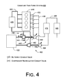
- Fig. 4 is a diagram of an exemplary twin turbocharger system
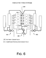
- Fig. 6 is a diagram of an exemplary mulit-plenum system
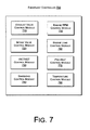
- Fig. 7 is a diagram of an exemplary controller for controlling flow of exhaust and optionally other aspects of an internal combustion engine
- Fig. 8 is a diagram of an exemplary twin path intake manifold system for selectively directing intake air to a cylinder
- Fig. 9 is a diagram of an exemplary system with twin exhaust paths to a single exhaust turbine.
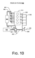
- Fig. 10 is a diagram of an exemplary system with twin intake paths and twin exhaust paths to a single exhaust turbine.
- an exemplary controller includes one or more processors, memory and control logic to individually control at least one of two exhaust valves of a cylinder of an internal combustion engine to either provide exhaust from the cylinder to a single exhaust turbine or to provide exhaust from the cylinder to two exhaust turbines where the two exhaust valves are mounted in a cylinder head of the internal combustion engine.
- Such control logic may call for operation of one exhaust valve to provide exhaust to a single exhaust turbine and call for operation of two exhaust valves to provide exhaust to two exhaust turbines.
- a system includes a small exhaust turbine and a large exhaust turbine.
- An exemplary system can include a cylinder head for a multi-cylinder internal combustion engine where the cylinder head includes, per cylinder, a first exhaust valve and a corresponding first exhaust port and a second exhaust valve and a corresponding second exhaust port; a first manifold path to collect exhaust from the first exhaust ports and to direct the collected exhaust to a first exhaust turbine; and a second manifold path to collect exhaust from the second exhaust ports and to direct the collected exhaust to a second exhaust turbine.
- Such a system may include a manifold unit for defining the first manifold path and the second manifold path; alternatively, a first manifold defines the first manifold path and a second manifold defines the second manifold path.
- one exhaust turbine differs in size from another exhaust turbine.
- banks may be defined as a right bank and a left bank (e.g., as in a V8 configuration).
- a system can include a right cylinder head for a right bank of cylinders where the cylinder head includes, per cylinder, two exhaust valves and two corresponding exhaust ports grouped to form two sets of exhaust ports for the right cylinder head; a left cylinder head for a left bank of cylinders where the cylinder head includes, per cylinder, two exhaust valves and two corresponding exhaust ports grouped to form two sets of exhaust ports for the left cylinder head; a first manifold path to direct exhaust from one set of the exhaust ports of the right cylinder head to a first turbocharger; a second manifold path to direct exhaust from one set of exhaust ports of the left cylinder head to a second turbocharger; and third and fourth manifold paths, the third path to direct exhaust from the other set of exhaust ports of the right cylinder head to a third turbocharger and the fourth path to direct exhaust from the other set of exhaust
- Fig. 1 shows an exemplary system 100 that includes a twin path exhaust manifold.
- the system 100 includes a piston 112 connected to a piston shaft 114.
- the piston 112 includes various head features including wells 116 to accommodate valves and a well to accommodate an ignition plug (e.g., a spark plug).
- a common intake 120 bifurcates to individual intake paths 122, 124 that are controlled by respective intake valves 132, 134.
- Two exhaust valves 136, 138 control flow of exhaust to respective exhaust paths 146, 148.
- the exhaust paths 146, 148 remain separate where each path can be directed to a respective exhaust turbine.
- a manifold directs exhaust from a plurality of cylinders to a common path.
- a manifold includes manifold paths, for example, defined by pipes, a cast unit, etc.
- Various examples described herein include two sets of manifold paths. For example, referring to the system 100 of Fig. 1 , each cylinder may have two exhaust valves where one valve provides exhaust to a path of one set and another exhaust valve provides exhaust to a path of the other set.
- intake air is provided to a cylinder via one or more plenums.
- a plenum includes a plurality of paths to direct intake air to a plurality of cylinders.
- common intake 120 for the cylinder is a path of a plenum, that typically bifurcates at a cylinder head to provide intake air to the intake valves 132, 134.
- a system may include multiple plenums , for example, where each plenum provides air to a single intake valve of each cylinder in a cylinder bank (see, e.g., Fig. 8 ).
- an exhaust manifold or a plenum may be a configured to attach to a cylinder head or may, alternatively, be part of a cylinder head.
- a so-called integrated exhaust manifold (IEM) is a cylinder head with a built in manifold.
- a typically IEM has a single exhaust outlet.
- An exhaust turbine may connect to an IEM outlet or be positioned at a distance from an IEM via an exhaust pipe that attaches to an IEM outlet.
- Fig. 1 also shows a conventional timing plot 160 characteristic of a conventional system with a common path exhaust manifold and an exemplary timing plot 170 characteristic of the exemplary system 100 with the exemplary twin path exhaust manifold.
- the plots 160, 170 include labels A through E for respective events that occur successively in time.
- an exhaust valve or exhaust valves are opened simultaneously with identical amplitude and duration to provide for flow of exhaust to a common path manifold that collects exhaust from multiple cylinders. Further, even if such a conventional system had more than one exhaust valve, it is standard practice that each valve flows to a path that merges to a common path after some short distance (e.g., within 10 centimeters or about 5 inches). Yet further, in conventional systems with more than one exhaust valve, it is standard practice that each valve is identical and controlled via a common control mechanism.
- the exhaust valves 136, 138 may be controlled individually according to one or more of the following criteria: timing, amplitude and duration. Alternatively, or in addition to such control, the exhaust valves 136, 138 may differ in shape, including size. Hence, even if a controller controlled the valves in a simultaneous manner, each valve would deliver a different amount of exhaust to its respective exhaust path 146, 148.
- the events A through E of the plot 170 are for purposes of explaining how the two exhaust valves 136, 138 may be controlled.
- event A only the valve 136 is opened.
- event B the valve 136 is opened before the valve 138 and with greater amplitude and duration.
- event C compared to event B, the valve 138 is opened with greater duration.
- event D compared to event C, the valve 138 is opened earlier and with greater duration.
- event E compared to event D, the valve 136 is opened with a shorter duration.
- Fig. 2 shows conventional exhaust ports 210 and some exemplary exhaust ports 220, 230.
- exhaust ports are shown schematically as filled portions and optional intake ports as unfilled portions.
- a 4 cylinder engine may have a cylinder head with exhaust and intake ports on the same side; whereas, for "V" configured engine, exhaust and intake ports may be on opposite side of a cylinder head.
- the exhaust ports of Fig. 2 are shown as being associated, for example, with a cylinder head for four cylinders.
- the conventional ports 210 are of identical shape where there is one exhaust port per cylinder.
- an exhaust manifold collects exhaust from each port and directs the flow of exhaust to a common path.
- there are two exhaust ports per cylinder (labeled R and L). As described herein, all of the "R" ports connect to a first common path and all of the "L" ports connect to a second common path where the first common path may be directed to a first exhaust turbine and where the second common path may be directed to a second exhaust turbine.
- the first common path may be defined by a first manifold and the second common may be defined by a second manifold.
- a single manifold defines the first common path and the second common path.
- a single manifold may be cast with two internal and separate manifolds and connected to a cylinder head; as opposed to two individually cast manifolds where each of these manifolds is connected to the same cylinder head.
- Fig. 3 shows a conventional twin turbocharger system 300.
- the system 300 includes a first bank of cylinders 310 and a second bank of cylinders 312, for example, arranged in a "V" as in a V8 engine.
- An intake 320 provides intake air to a plenum 330 that distributes intake air to the cylinders in the banks 310, 312.
- each cylinder normally includes at least one intake valve to control the flow of intake air to the cylinder.
- a cooler 325 may cool intake air.
- the system 300 includes a first turbocharger 340 and a second turbocharger 360.
- the first turbocharger 340 includes a compressor 342 and a turbine 344 coupled to a common shaft 346.
- the first turbocharger 340 is powered by exhaust flowing from the first bank 310 via an exhaust manifold 333.
- the second turbocharger 360 includes a compressor 362 and a turbine 364 coupled to a common shaft 366.
- the second turbocharger 360 is powered by exhaust flowing from the second bank 312 via an exhaust manifold 335.
- the turbochargers 340, 360 receive substantially similar exhaust flows when the banks 310 and 312 are operated similarly.
- the system 300 includes a conduit valve 350 that controls the flow of exhaust in exhaust conduits.
- the conduit valve 350 may be referred to as a bypass valve as it can cause exhaust to bypass the first turbocharger 340.
- Exhaust exits the turbines 344, 364 via an exhaust outlet 380 that may provide a path for flow of exhaust to an exhaust treatment unit and then to the atmosphere.
- the downstream conduit valve 350 may be removed to reduce the number of elements and potential leakage through exhaust system.
- Fig. 4 shows an exemplary twin turbocharger system 400.
- the system 400 includes a single bank of cylinders 410; noting that other arrangements are possible.
- An intake filtering unit 422 provides intake air to a plenum 430 that distributes intake air to the cylinders in the bank 410.
- each cylinder normally includes at least one intake valve to control the flow of intake air to the cylinder.
- a cooler 425 may cool intake air.
- the system 400 includes a first turbocharger 440 and a second turbocharger 460.
- the first turbocharger 440 includes a compressor 442 and a turbine 444 coupled to a common shaft 446.
- the first turbocharger 440 is powered by exhaust flowing from the bank 410 via a first exhaust manifold 433.
- the second turbocharger 460 includes a compressor 462 and a turbine 464 coupled to a common shaft 466.
- the second turbocharger 460 is powered by exhaust flowing from the bank 310 via a second exhaust manifold 435.
- each cylinder in a bank of cylinders have two or more exhaust valves where the valves control flow of exhaust from the cylinder to more than one exhaust path.
- the first manifold 433 forms a first exhaust path that may be directed to the exhaust turbine 444 and the second manifold forms a second exhaust path that may be directed to the exhaust turbine 464.
- the turbochargers 440, 460 may receive substantially similar exhaust flows or may receive substantially different exhaust flows. For example, as explained with respect to Fig. 1 , where each cylinder in the bank 410 includes two exhaust valves that may be controlled differently, then such control may cause the exhaust flow in the manifold 433 to differ from the exhaust flow in the manifold 435. Consequently, the exhaust turbines 444 and 464 may receive different quantities and/or qualities of exhaust from the bank 410. Alternatively, or in addition to, the shape of the first manifold 433 and the second manifold 435 may differ to thereby cause the exhaust flow to the exhaust turbine 444 and the exhaust turbine 464 to differ in quantity and/or quality.
- one manifold may be operates so as to preheat or cause a temperature change in the other manifold.
- valve control may cause exhaust to flow from the cylinders in the bank 410 to the first manifold 433 for a period of time while such control causes no exhaust to flow to the second manifold 435 for that period of time.
- exhaust flow along a first manifold path will cause the unit to heat the walls of the second manifold path.
- preheating can ensure that heat is not lost when a control decision is made to direct exhaust to the second manifold path and on to the exhaust turbine 464.
- Such a method can ensure proper delivery of energy to intake air by the compressor 462.
- exhaust exits the turbines 444, 464 via an exhaust treatment unit 475.
- the output of the unit 475 is collected by an exhaust outlet 480 that may provide a path for flow of exhaust to another exhaust treatment unit and/or noise abatement unit 485 and then to the atmosphere.
- the quality and/or quantity of exhaust provided to the exhaust treatment unit 475 may be controlled to enhance operation of the unit 475.
- a controller may cause exhaust valves for the cylinder bank 410 to direct all exhaust to the manifold 433 to ensure proper quantity and quality of exhaust to treat a catalyst in the exhaust treatment unit 475.
- Such a method may aim to regenerate a catalyst in an exhaust treatment unit to facilitate the catalyst light off.
- Amplitude or "lift” refers to how much the valve is opened. Duration refers to how long the valve is kept open. Due to the behavior of the working fluid (air and fuel mixture) before and after combustion, which have physical limitations on their flow, as well as their interaction with the ignition spark, the optimal valve timing, lift and duration settings under low rpm engine operations are very different from those under high rpm. Optimal low rpm valve timing, lift and duration settings would result in insufficient filling of the cylinder with fuel and air at high rpm, thus greatly limiting engine power output. Conversely, optimal high rpm valve timing, lift and duration settings would result in very rough low rpm operation and difficult idling. The "ideal" conventional engine would have fully variable valve timing, lift and duration, in which the valves would always open at exactly the right point, lift high enough and stay open just the right amount of time for the engine speed in use.
- an exemplary engine includes two separate exhaust flow paths per cylinder where each path can provide exhaust to a respective exhaust turbine where the exhaust provided by each path may be controlled, for example, by a control scheme (see, e.g., the plot 170 of Fig. 1 ).
- a control scheme see, e.g., the plot 170 of Fig. 1 .
- the engine of Fig. 4 can operate using 8 valves (one intake valve and one exhaust valve per cylinder) to selectively operate the turbocharger 460 and, at high rpm the engine of Fig. 4 can operate using 16 valves (two intake valves and two exhaust valves per cylinder) to selectively operate the turbocharger 440 and the turbocharger 460.
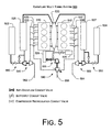
- Fig. 5 shows an exemplary multi-turbocharger system 500 that includes a first turbocharger 540, a second turbocharger 560 and a third turbocharger 590.
- the system 500 includes a first bank of cylinders 510 and a second bank of cylinders 512 and an exhaust system that can distribute exhaust from the first bank of cylinders 510 to an exhaust turbine of the first turbocharger 540 and an exhaust turbine of the third turbocharger 590 and that can distribute exhaust from the second bank of cylinders 512 to an exhaust turbine of the second turbocharger 560 and an exhaust turbine of the third turbocharger 590.
- the system 500 includes three air filtration units 522, 524, 526 and three coolers 525, 527, 529.
- Conduit valve systems 550, 553, 555 allow for bypassing (or re-circulating) air associated with respective compressors of the first, second and third turbochargers 540, 560, 590. Air is provided to both banks of cylinders 510, 512 via single plenum 530.
- Fig. 6 shows an exemplary multi-plenum system 600 with two plenums 632, 634 where the plenum 632 is associated with turbochargers 640, 660 and the plenum 634 is associated with a turbocharger 690.
- the plenum 632 is associated with turbochargers 640, 660 and the plenum 634 is associated with a turbocharger 690.
- Other arrangements are also possible.
- Various other features may be the same as those identified in Figs. 1 , 2 , 4 and 5 .
- the individual plenums may be controlled individually or in conjunction to achieve a desired result. For example, when only one of the plenums is in operation, then only a single inlet valve per cylinder allows for inflow to each cylinder. In other words, each of the separate plenums 632, 634 feeds a single intake valve per cylinder yet each plenum feeds every cylinder.
- the individual intake paths 122, 124 would not be connected to the common intake 120; instead, for example, the intake path 122 would be connected to the plenum 632 and the intake path 124 would be connected to the plenum 634. Accordingly, the intake valve 132 would operate to provide flow to the cylinder from the plenum 632 and the intake valve 134 would operate to provide flow to the cylinder from the plenum 634.
- the controller 700 may include one or more processors, memory and control logic to perform one or more methods.
- the controller 700 may include control logic to selectively operate one of two exhaust valves to provide exhaust to a single exhaust turbine in a system with multiple exhaust turbines.
- the controller 700 may include various features typically included in a conventional engine control unit (ECU).
- the controller 700 can include circuitry, an input for power, one or more inputs to receive commands, engine operational conditions and/or environmental conditions (e.g., outside temperature, humidity, atmospheric pressure, etc.), and one or more outputs to control an exhaust valve or valves, an intake valve or valves, etc.
- Control logic may be in the form of one or more computer-readable storage media that includes instructions thereon to perform one or more tasks.
- the controller 700 may, in some examples, be considered a computer or computing device.
- each cylinder (or piston) can have at least two exhaust valves mounted in the cylinder heads where these valves selectively control the flow of exhaust to exhaust turbines.
- Such exhaust valves may differ in shape/size depending on matching requirement (e.g., to match flow of exhaust to one or more exhaust turbines).
- the exhaust port of a cylinder head for a first exhaust turbine may differ from the exhaust port of the cylinder head for a second exhaust turbine.
- one exhaust port for a cylinder may have a larger cross-sectional area or a different volumetric shape than another exhaust port for that cylinder.
- a manifold may be a "single" manifold with two passages or two distinct manifolds.
- manifold pipes may be separate or one manifold block may be used and optionally cast as a unit with separate passages.
- the corresponding exhaust path can warm-up an adjacent, separate exhaust path.
- a preheated exhaust path can increase responsiveness of a turbocharger.
- EGR exhaust gas recirculation
- Various systems may be configured to avoid complexity of a so-called long route (low pressure) EGR and operated to improve knock resistance, transient response, etc.
- an exemplary system alleviate the need for an external by-pass valve, which, in turn, can simplify piping architecture and minimize system mass.
- an exemplary system instead of one large turbocharger that runs for high load and/or high engine rpm, an exemplary system includes two or more turbochargers.
- a system may operate two smaller turbochargers with a small manifold (e.g., volume basically dived by two versus a standard parallel architecture). Such a volume reduction is good for permeability, transient response and catalyst light off.
- a small exhaust turbine is easier to spool than a larger exhaust turbine; however, as exhaust flow increases, a small exhaust turbine may not handle the increased exhaust flow as well as a larger exhaust turbine. Accordingly, various exemplary systems and controllers may account for such characteristics and a system may include exhaust turbines of different size. Further, a system may include one or more motorized components such as a motorized compressor or a motorized turbocharger. Yet further, an exhaust turbine may be coupled to a generator to generate electrical energy. Such energy may be used immediately or stored. Uses for electrical energy may include driving a motor coupled to a shaft (e.g., a driveshaft, a compressor wheel shaft, etc.).
- a shaft e.g., a driveshaft, a compressor wheel shaft, etc.
- an exemplary system selectively controls flow of exhaust to two or more exhaust turbines via two exhaust valves positioned in a cylinder head where the cylinder head includes, for each cylinder, an exhaust port for each exhaust valve (i.e., two exhaust ports).
- a system can alleviate the need for "downstream" valves to control flow of exhaust to multiple exhaust turbines.
- Fig. 8 shows an exemplary system 800 that includes a twin path intake characteristic of a double plenum architecture (see, e.g., plenums 632, 634 of Fig. 6 ).
- the system 800 includes a piston 812 connected to a piston shaft 814.
- the piston 812 includes various head features including wells 816 to accommodate valves and a well to accommodate an ignition plug (e.g., a spark plug).
- two individual intake paths 822, 824 are controlled by respective intake valves 832, 834.
- Two exhaust valves 836, 838 control flow of exhaust to respective exhaust paths 846, 848, which join a common path 850.
- the example of Fig. 8 optionally includes an exhaust arrangement as shown in the system 100 of Fig. 1 where separate exhaust paths can be directed to a respective exhaust turbine.
- Fig. 8 also shows an exemplary timing plot 870 characteristic of the exemplary system 800 with the exemplary twin path intake.
- the plot 870 includes labels A through E for respective events that occur successively in time.
- the intake valves 832, 834 may be controlled individually according to one or more of the following criteria: timing, amplitude and duration. Alternatively, or in addition to such control, the intake valves 832, 834 may differ in shape, including size. Hence, even if a controller (e.g., the controller 700) controlled the valves in a simultaneous manner, each valve would deliver a different amount of intake air the cylinder.
- a controller e.g., the controller 700
- the events A through E of the plot 870 are for purposes of explaining how the two intake valves 832, 834 may be controlled.
- event A only the valve 832 is opened.
- event B the valve 832 is opened before the valve 834 and with greater amplitude and duration.
- event C compared to event B, the valve 834 is opened with greater duration.
- event D compared to event C, the valve 834 is opened earlier and with greater duration.
- event E compared to event D, the valve 834 is opened with a shorter duration.
- a cylinder head for the system 800 may have any of a variety of port arrangements.
- a cylinder head may have two intake ports and two exhaust ports (e.g., one port per valve).
- An exemplary cylinder head may have the intake port configured to receive air from two separate intake paths (e.g., two intake plenums).
- the intake ports (unfilled) would appear as two separate ports per cylinder instead of a single port per cylinder.
- the system 900 also includes an intake filtering unit 922 that provides intake air to an intake plenum path 930 that distributes intake air to the cylinders in the bank 910.
- One or more valves 950 allow for use of or bypass of a compressor 942 of the turbocharger 940.
- a cooler 925 may cool intake air.
- turbocharger 940 is powered by exhaust flowing from the bank 910 via one or both exhaust manifolds 933, 935; exhaust exits the exhaust turbine 944 via path 980, which may continue to an exhaust treatment unit.
- a controller such as the controller 700 of Fig. 7 may be configured to control the system 900 of Fig. 9 .
- An exemplary system includes a cylinder head (for a multi-cylinder internal combustion engine) that includes, per cylinder, a first intake valve and a corresponding first intake port and a second intake valve and a corresponding second intake port; a first manifold path to direct intake air to the first intake ports; a second manifold path to direct intake air to the second intake ports; and a controller to individually control, per cylinder, at least the first intake valve or at least the second intake valve.
- a system can include a single turbocharger configured to provide compressed intake air to the first manifold path, the second manifold path or the first manifold path and the second manifold path.
- the first intake port and the second intake port may differ in shape, for example, to handle different intake flows.
Applications Claiming Priority (1)
| Application Number | Priority Date | Filing Date | Title |
|---|---|---|---|
| US12/121,100 US8000878B2 (en) | 2008-05-15 | 2008-05-15 | Parallel sequential turbocharger architecture using engine cylinder variable valve lift system |
Publications (3)
| Publication Number | Publication Date |
|---|---|
| EP2119888A2 true EP2119888A2 (de) | 2009-11-18 |
| EP2119888A3 EP2119888A3 (de) | 2016-04-06 |
| EP2119888B1 EP2119888B1 (de) | 2017-12-20 |
Family
ID=40885985
Family Applications (1)
| Application Number | Title | Priority Date | Filing Date |
|---|---|---|---|
| EP09159471.3A Not-in-force EP2119888B1 (de) | 2008-05-15 | 2009-05-05 | Parallel-sequentielle Turboladerarchitektur unter Verwendung eines Motorzylinderventiltriebs mit variablem Ventilhub |
Country Status (2)
| Country | Link |
|---|---|
| US (3) | US8000878B2 (de) |
| EP (1) | EP2119888B1 (de) |
Cited By (5)
| Publication number | Priority date | Publication date | Assignee | Title |
|---|---|---|---|---|
| EP2620631A1 (de) * | 2012-01-30 | 2013-07-31 | Peugeot Citroën Automobiles Sa | Brennkraftmaschine mit zwei Auslasskrümmern |
| WO2014195256A1 (en) * | 2013-06-04 | 2014-12-11 | Jaguar Land Rover Limited | Exhaust turbocharger |
| WO2015176803A1 (de) * | 2014-05-17 | 2015-11-26 | Daimler Ag | Viertakt-hubkolben-verbrennungsmotor mit einem abgasturbolader und betriebsverfahren hierfür |
| WO2018046198A1 (de) | 2016-09-09 | 2018-03-15 | Volkswagen Aktiengesellschaft | Brennkraftmaschine und verfahren zum betreiben einer brennkraftmaschine |
| DE102013112830B4 (de) | 2012-12-31 | 2020-07-30 | Hyundai Motor Company | Turboladersystem |
Families Citing this family (24)
| Publication number | Priority date | Publication date | Assignee | Title |
|---|---|---|---|---|
| JP4341706B2 (ja) * | 2007-07-18 | 2009-10-07 | トヨタ自動車株式会社 | 内燃機関の制御装置 |
| US8000878B2 (en) * | 2008-05-15 | 2011-08-16 | Honeywell International Inc. | Parallel sequential turbocharger architecture using engine cylinder variable valve lift system |
| DE102008048681B4 (de) * | 2008-09-24 | 2019-08-08 | Audi Ag | Brennkraftmaschine mit zwei Ladern und Verfahren zum Betreiben derselben |
| GB2457326B (en) * | 2008-10-17 | 2010-01-06 | Univ Loughborough | An exhaust arrangement for an internal combustion engine |
| DE102010037186B4 (de) | 2010-06-21 | 2022-07-07 | Dr. Ing. H.C. F. Porsche Aktiengesellschaft | Brennkraftmaschine mit zwei Zylinderreihen |
| US10316741B2 (en) | 2010-10-14 | 2019-06-11 | Ford Global Technologies, Llc | Turbocharged combustion system |
| EP2503126B1 (de) * | 2011-03-25 | 2014-08-27 | Ford Global Technologies, LLC | Mit Waste-Gate-Turbinen ausgestattete Brennkraftmaschine und Verfahren zum Betreiben einer derartigen Brennkraftmaschine |
| US8950183B2 (en) * | 2012-09-10 | 2015-02-10 | Caterpillar Inc. | Engine system having intake conduit with surge inhibitor and method |
| US9279393B2 (en) * | 2013-01-17 | 2016-03-08 | Ford Global Technologies, Llc | Devices and methods for exhaust gas recirculation operation of an engine |
| US9200599B2 (en) * | 2013-04-15 | 2015-12-01 | Southwest Research Institute | Internal combustion engine having dual EGR loops (dedicated EGR loop and low pressure EGR loop) and dual cylinder intake ports |
| US9447754B1 (en) | 2015-07-02 | 2016-09-20 | Bright Acceleration Technologies LLC | Method and apparatus for internal combustion engine system with improved turbocharging |
| US10697357B2 (en) | 2016-09-01 | 2020-06-30 | Bright Acceleration Technologies LLC | Cross-port air flow to reduce pumping losses |
| US10364739B2 (en) | 2016-09-01 | 2019-07-30 | Bright Acceleration Technologies LLC | Synergistic induction and turbocharging in internal combustion engine systems |
| US10107215B2 (en) | 2016-09-01 | 2018-10-23 | Bright Acceleration Technologies LLC | Synergistic induction and turbocharging in internal combustion engine systems |
| US9638095B1 (en) | 2016-09-01 | 2017-05-02 | Bright Acceleration Technologies LLC | Synergistic induction and turbocharging in internal combustion engine systems |
| DE102016011551B4 (de) * | 2016-09-23 | 2018-05-09 | Mtu Friedrichshafen Gmbh | Brennkraftmaschine |
| US10012159B1 (en) * | 2016-12-16 | 2018-07-03 | Ford Global Technologies, Llc | Systems and methods for a split exhaust engine system |
| US10107220B2 (en) * | 2016-12-16 | 2018-10-23 | Ford Global Technologies, Llc | Systems and methods for a split exhaust engine system |
| US10190507B2 (en) | 2016-12-16 | 2019-01-29 | Ford Global Technologies, Llc | Systems and methods for a split exhaust engine system |
| US10132235B2 (en) * | 2016-12-16 | 2018-11-20 | Ford Global Technologies, Llc | Systems and methods for a split exhaust engine system |
| US10138822B2 (en) * | 2016-12-16 | 2018-11-27 | Ford Global Technologies, Llc | Systems and methods for a split exhaust engine system |
| US10570822B2 (en) | 2017-06-26 | 2020-02-25 | Garrett Transportation I Inc. | Exhaust manifold system for turbocharger device with plural volute members |
| GB201719042D0 (en) * | 2017-11-17 | 2018-01-03 | Oxford Two Stroke Ltd | Internal combustion engine |
| CN114622989A (zh) * | 2022-02-23 | 2022-06-14 | 中国第一汽车股份有限公司 | 发动机及具有其的车辆和发动机的控制方法 |
Family Cites Families (31)
| Publication number | Priority date | Publication date | Assignee | Title |
|---|---|---|---|---|
| JPS57124023A (en) * | 1981-01-26 | 1982-08-02 | Mazda Motor Corp | Secondary air feeder for multicylinder engine with supercharger |
| IT1158845B (it) * | 1983-03-25 | 1987-02-25 | Fiat Auto Spa | Motore a combustione interna sovra limentato con testata a quattro valvole per cilindro |
| DE3439999C1 (de) * | 1984-11-02 | 1986-05-15 | Audi AG, 8070 Ingolstadt | Viertakt-Brennkraftmaschine mit zwei Abgasturboladern |
| JPS61164039A (ja) | 1985-01-11 | 1986-07-24 | Nissan Motor Co Ltd | 多段タ−ボ過給機関 |
| JPS61210224A (ja) | 1985-03-14 | 1986-09-18 | Mazda Motor Corp | 排気タ−ボ過給機付エンジン |
| DE3623540C1 (de) * | 1986-07-12 | 1987-08-20 | Porsche Ag | Mehrzylinder-Brennkraftmaschine mit zwei Abgasturboladern |
| JP2815213B2 (ja) * | 1990-02-05 | 1998-10-27 | マツダ株式会社 | エンジンの燃料制御装置 |
| US6436078B1 (en) * | 1994-12-06 | 2002-08-20 | Pal Svedman | Transdermal perfusion of fluids |
| JPH06280586A (ja) | 1993-03-31 | 1994-10-04 | Hino Motors Ltd | エンジンのターボ・チャージャ制御装置 |
| US6251100B1 (en) * | 1993-09-24 | 2001-06-26 | Transmedica International, Inc. | Laser assisted topical anesthetic permeation |
| US5582578A (en) * | 1995-08-01 | 1996-12-10 | Duke University | Method for the comminution of concretions |
| DE19615033A1 (de) * | 1996-04-17 | 1997-10-23 | Bosch Gmbh Robert | Anordnung zum Erkennen von Drehzahlabweichungen zwischen zwei Abgasturboladern |
| US6659105B2 (en) * | 1998-02-26 | 2003-12-09 | Senorx, Inc. | Tissue specimen isolating and damaging device and method |
| US6309355B1 (en) * | 1998-12-22 | 2001-10-30 | The Regents Of The University Of Michigan | Method and assembly for performing ultrasound surgery using cavitation |
| US20030078499A1 (en) * | 1999-08-12 | 2003-04-24 | Eppstein Jonathan A. | Microporation of tissue for delivery of bioactive agents |
| US20020099356A1 (en) * | 2001-01-19 | 2002-07-25 | Unger Evan C. | Transmembrane transport apparatus and method |
| SE519321C2 (sv) * | 2001-06-29 | 2003-02-11 | Saab Automobile | Sätt att driva en förbränningsmotor samt förbränningsmotor |
| AU2002354042A1 (en) * | 2001-11-06 | 2003-05-19 | The Johns Hopkins University | Device for thermal stimulation of small neural fibers |
| DE10243473A1 (de) | 2002-09-19 | 2004-03-25 | Dr.Ing.H.C. F. Porsche Ag | Brennkraftmaschine mit Abgasturboaufladung |
| DE602005000777T2 (de) * | 2004-01-14 | 2008-01-10 | Group Lotus Plc, Norwich | Brennkraftmaschine |
| US6957632B1 (en) * | 2004-05-20 | 2005-10-25 | Ford Global Technologies, Llc | Air charging system for an opposed piston opposed cylinder free piston engine |
| SE0402409L (sv) * | 2004-10-06 | 2005-08-09 | Saab Automobile | Förbränningsmotor med parallellt arbetande turboaggregat, samt metod för reglering |
| DE102004058371A1 (de) * | 2004-12-03 | 2006-06-14 | Daimlerchrysler Ag | Brennkraftmaschine mit Abgasaufladung |
| FR2884866B1 (fr) * | 2005-04-22 | 2011-06-10 | Renault Sas | Moteur a suralimentation sequentielle et a distribution variable |
| US7275516B1 (en) * | 2006-03-20 | 2007-10-02 | Ford Global Technologies, Llc | System and method for boosted direct injection engine |
| US20070277779A1 (en) * | 2006-05-31 | 2007-12-06 | Caterpillar Inc. | System for exhaust valve actuation |
| GB2439329B (en) * | 2006-06-23 | 2011-04-06 | Ford Global Tech Llc | Control stategy for turbocharged diesel engine |
| DE102007046657A1 (de) | 2007-09-28 | 2009-04-09 | Audi Ag | Brennkraftmaschine |
| JP5040747B2 (ja) * | 2008-03-14 | 2012-10-03 | マツダ株式会社 | 過給機付きエンジン |
| US8000878B2 (en) * | 2008-05-15 | 2011-08-16 | Honeywell International Inc. | Parallel sequential turbocharger architecture using engine cylinder variable valve lift system |
| US8365528B2 (en) * | 2009-01-06 | 2013-02-05 | Ford Global Technologies, Llc | Engine valve duration control for improved scavenging |
-
2008
- 2008-05-15 US US12/121,100 patent/US8000878B2/en not_active Expired - Fee Related
-
2009
- 2009-05-05 EP EP09159471.3A patent/EP2119888B1/de not_active Not-in-force
-
2011
- 2011-07-28 US US13/193,037 patent/US8160803B2/en active Active
-
2012
- 2012-04-15 US US13/447,226 patent/US8442743B2/en active Active
Cited By (10)
| Publication number | Priority date | Publication date | Assignee | Title |
|---|---|---|---|---|
| EP2620631A1 (de) * | 2012-01-30 | 2013-07-31 | Peugeot Citroën Automobiles Sa | Brennkraftmaschine mit zwei Auslasskrümmern |
| FR2986276A1 (fr) * | 2012-01-30 | 2013-08-02 | Peugeot Citroen Automobiles Sa | Groupe moteur a deux collecteurs d'echappement |
| DE102013112830B4 (de) | 2012-12-31 | 2020-07-30 | Hyundai Motor Company | Turboladersystem |
| WO2014195256A1 (en) * | 2013-06-04 | 2014-12-11 | Jaguar Land Rover Limited | Exhaust turbocharger |
| US9759125B2 (en) | 2013-06-04 | 2017-09-12 | Jaguar Land Rover Limited | Exhaust turbocharger |
| WO2015176803A1 (de) * | 2014-05-17 | 2015-11-26 | Daimler Ag | Viertakt-hubkolben-verbrennungsmotor mit einem abgasturbolader und betriebsverfahren hierfür |
| CN106414946A (zh) * | 2014-05-17 | 2017-02-15 | 戴姆勒股份公司 | 具有废气涡轮增压器的四冲程往复式内燃机及用于这种内燃机的运行方法 |
| US10094269B2 (en) | 2014-05-17 | 2018-10-09 | Daimler Ag | Four-stroke reciprocating piston internal combustion engine having an exhaust gas turbocharger, and operating method for same |
| WO2018046198A1 (de) | 2016-09-09 | 2018-03-15 | Volkswagen Aktiengesellschaft | Brennkraftmaschine und verfahren zum betreiben einer brennkraftmaschine |
| DE102016217265A1 (de) | 2016-09-09 | 2018-03-15 | Volkswagen Aktiengesellschaft | Brennkraftmaschine und Verfahren zum Betreiben einer Brennkraftmaschine |
Also Published As
| Publication number | Publication date |
|---|---|
| US8000878B2 (en) | 2011-08-16 |
| EP2119888A3 (de) | 2016-04-06 |
| US20120198822A1 (en) | 2012-08-09 |
| US20110283696A1 (en) | 2011-11-24 |
| US8442743B2 (en) | 2013-05-14 |
| US8160803B2 (en) | 2012-04-17 |
| US20090287397A1 (en) | 2009-11-19 |
| EP2119888B1 (de) | 2017-12-20 |
Similar Documents
| Publication | Publication Date | Title |
|---|---|---|
| EP2119888B1 (de) | Parallel-sequentielle Turboladerarchitektur unter Verwendung eines Motorzylinderventiltriebs mit variablem Ventilhub | |
| US8904786B2 (en) | Internal combustion engine | |
| US7908860B2 (en) | Split-series sequential turbocharged engine | |
| US9086011B2 (en) | Directly communicated turbocharger | |
| US8250866B2 (en) | EGR extraction immediately downstream pre-turbo catalyst | |
| US8931462B2 (en) | EGR system for an internal combustion engine that feeds exhaust gas independent of intake air | |
| US9121338B1 (en) | Two-stage turbocharger system for internal combustion engines featuring cylinder deactivation | |
| GB2430708A (en) | Turbocharging in a variable displacement i.c. engine, ie having cylinders selectively disabled | |
| CN102588131B (zh) | 汽车搭载用柴油发动机及其控制方法 | |
| US9062632B2 (en) | Internal combustion engine for a motor vehicle | |
| JP5919304B2 (ja) | ターボチャージャー付き車両用エンジン及びこれを含む車両 | |
| CN102889111A (zh) | 二次空气喷射系统和方法 | |
| JP2005054771A (ja) | 気筒群個別制御エンジン | |
| EP1766204A1 (de) | Anordnung zur steuerung von abgasdruckimpulsen an einem verbrennungsmotor | |
| RU140698U1 (ru) | Система (варианты) | |
| US9726121B2 (en) | Engine system having reduced pressure EGR system | |
| US20030159443A1 (en) | Two-stage supercharging on a V-engine | |
| JP2011214552A (ja) | 内燃機関 | |
| JP2009293537A (ja) | 内燃機関の制御装置 | |
| RU151787U1 (ru) | Двигатель внутреннего сгорания | |
| CN109681285A (zh) | 发动机系统 | |
| WO2011005560A2 (en) | Engine breathing system, components and method thereof | |
| JP2005330836A (ja) | 通路連通制御弁により制御される過給式多気筒内燃機関 | |
| JP6032802B2 (ja) | Egr装置 | |
| JP2011208596A (ja) | 内燃機関の制御装置 |
Legal Events
| Date | Code | Title | Description |
|---|---|---|---|
| PUAI | Public reference made under article 153(3) epc to a published international application that has entered the european phase |
Free format text: ORIGINAL CODE: 0009012 |
|
| 17P | Request for examination filed |
Effective date: 20090505 |
|
| AK | Designated contracting states |
Kind code of ref document: A2 Designated state(s): AT BE BG CH CY CZ DE DK EE ES FI FR GB GR HR HU IE IS IT LI LT LU LV MC MK MT NL NO PL PT RO SE SI SK TR |
|
| RAP1 | Party data changed (applicant data changed or rights of an application transferred) |
Owner name: HONEYWELL INTERNATIONAL INC. |
|
| PUAL | Search report despatched |
Free format text: ORIGINAL CODE: 0009013 |
|
| AK | Designated contracting states |
Kind code of ref document: A3 Designated state(s): AT BE BG CH CY CZ DE DK EE ES FI FR GB GR HR HU IE IS IT LI LT LU LV MC MK MT NL NO PL PT RO SE SI SK TR |
|
| AX | Request for extension of the european patent |
Extension state: AL BA RS |
|
| RIC1 | Information provided on ipc code assigned before grant |
Ipc: F02M 35/108 20060101ALI20160226BHEP Ipc: F02D 41/00 20060101ALI20160226BHEP Ipc: F02B 75/22 20060101ALI20160226BHEP Ipc: F02B 37/007 20060101AFI20160226BHEP Ipc: F02D 23/00 20060101ALI20160226BHEP |
|
| 17Q | First examination report despatched |
Effective date: 20160531 |
|
| STAA | Information on the status of an ep patent application or granted ep patent |
Free format text: STATUS: EXAMINATION IS IN PROGRESS |
|
| RIC1 | Information provided on ipc code assigned before grant |
Ipc: F02B 75/22 20060101ALI20170221BHEP Ipc: F02M 35/108 20060101ALI20170221BHEP Ipc: F02B 37/007 20060101AFI20170221BHEP Ipc: F02D 23/00 20060101ALI20170221BHEP Ipc: F02D 41/26 20060101ALI20170221BHEP Ipc: F01N 13/10 20100101ALI20170221BHEP Ipc: F02D 41/00 20060101ALI20170221BHEP |
|
| GRAP | Despatch of communication of intention to grant a patent |
Free format text: ORIGINAL CODE: EPIDOSNIGR1 |
|
| STAA | Information on the status of an ep patent application or granted ep patent |
Free format text: STATUS: GRANT OF PATENT IS INTENDED |
|
| RIC1 | Information provided on ipc code assigned before grant |
Ipc: F02B 29/04 20060101ALI20170711BHEP Ipc: F02M 35/108 20060101ALI20170711BHEP Ipc: F02M 35/10 20060101ALI20170711BHEP Ipc: F02B 37/007 20060101AFI20170711BHEP Ipc: F01N 13/10 20100101ALI20170711BHEP Ipc: F02D 41/26 20060101ALI20170711BHEP Ipc: F02B 37/22 20060101ALI20170711BHEP Ipc: F02D 13/02 20060101ALI20170711BHEP Ipc: F02D 23/00 20060101ALI20170711BHEP Ipc: F02D 41/00 20060101ALI20170711BHEP Ipc: F02B 75/22 20060101ALI20170711BHEP |
|
| INTG | Intention to grant announced |
Effective date: 20170809 |
|
| RIN1 | Information on inventor provided before grant (corrected) |
Inventor name: LAISSUS, JEAN-JACQUES Inventor name: MASSARD, NICOLAS |
|
| GRAS | Grant fee paid |
Free format text: ORIGINAL CODE: EPIDOSNIGR3 |
|
| GRAA | (expected) grant |
Free format text: ORIGINAL CODE: 0009210 |
|
| STAA | Information on the status of an ep patent application or granted ep patent |
Free format text: STATUS: THE PATENT HAS BEEN GRANTED |
|
| AK | Designated contracting states |
Kind code of ref document: B1 Designated state(s): AT BE BG CH CY CZ DE DK EE ES FI FR GB GR HR HU IE IS IT LI LT LU LV MC MK MT NL NO PL PT RO SE SI SK TR |
|
| REG | Reference to a national code |
Ref country code: GB Ref legal event code: FG4D |
|
| REG | Reference to a national code |
Ref country code: CH Ref legal event code: EP |
|
| REG | Reference to a national code |
Ref country code: IE Ref legal event code: FG4D |
|
| REG | Reference to a national code |
Ref country code: AT Ref legal event code: REF Ref document number: 956606 Country of ref document: AT Kind code of ref document: T Effective date: 20180115 |
|
| REG | Reference to a national code |
Ref country code: DE Ref legal event code: R096 Ref document number: 602009049947 Country of ref document: DE |
|
| REG | Reference to a national code |
Ref country code: NL Ref legal event code: MP Effective date: 20171220 |
|
| PG25 | Lapsed in a contracting state [announced via postgrant information from national office to epo] |
Ref country code: NO Free format text: LAPSE BECAUSE OF FAILURE TO SUBMIT A TRANSLATION OF THE DESCRIPTION OR TO PAY THE FEE WITHIN THE PRESCRIBED TIME-LIMIT Effective date: 20180320 Ref country code: FI Free format text: LAPSE BECAUSE OF FAILURE TO SUBMIT A TRANSLATION OF THE DESCRIPTION OR TO PAY THE FEE WITHIN THE PRESCRIBED TIME-LIMIT Effective date: 20171220 Ref country code: SE Free format text: LAPSE BECAUSE OF FAILURE TO SUBMIT A TRANSLATION OF THE DESCRIPTION OR TO PAY THE FEE WITHIN THE PRESCRIBED TIME-LIMIT Effective date: 20171220 Ref country code: LT Free format text: LAPSE BECAUSE OF FAILURE TO SUBMIT A TRANSLATION OF THE DESCRIPTION OR TO PAY THE FEE WITHIN THE PRESCRIBED TIME-LIMIT Effective date: 20171220 |
|
| REG | Reference to a national code |
Ref country code: LT Ref legal event code: MG4D |
|
| REG | Reference to a national code |
Ref country code: AT Ref legal event code: MK05 Ref document number: 956606 Country of ref document: AT Kind code of ref document: T Effective date: 20171220 |
|
| REG | Reference to a national code |
Ref country code: FR Ref legal event code: PLFP Year of fee payment: 10 |
|
| PG25 | Lapsed in a contracting state [announced via postgrant information from national office to epo] |
Ref country code: LV Free format text: LAPSE BECAUSE OF FAILURE TO SUBMIT A TRANSLATION OF THE DESCRIPTION OR TO PAY THE FEE WITHIN THE PRESCRIBED TIME-LIMIT Effective date: 20171220 Ref country code: GR Free format text: LAPSE BECAUSE OF FAILURE TO SUBMIT A TRANSLATION OF THE DESCRIPTION OR TO PAY THE FEE WITHIN THE PRESCRIBED TIME-LIMIT Effective date: 20180321 Ref country code: BG Free format text: LAPSE BECAUSE OF FAILURE TO SUBMIT A TRANSLATION OF THE DESCRIPTION OR TO PAY THE FEE WITHIN THE PRESCRIBED TIME-LIMIT Effective date: 20180320 Ref country code: HR Free format text: LAPSE BECAUSE OF FAILURE TO SUBMIT A TRANSLATION OF THE DESCRIPTION OR TO PAY THE FEE WITHIN THE PRESCRIBED TIME-LIMIT Effective date: 20171220 |
|
| PG25 | Lapsed in a contracting state [announced via postgrant information from national office to epo] |
Ref country code: NL Free format text: LAPSE BECAUSE OF FAILURE TO SUBMIT A TRANSLATION OF THE DESCRIPTION OR TO PAY THE FEE WITHIN THE PRESCRIBED TIME-LIMIT Effective date: 20171220 |
|
| PG25 | Lapsed in a contracting state [announced via postgrant information from national office to epo] |
Ref country code: SK Free format text: LAPSE BECAUSE OF FAILURE TO SUBMIT A TRANSLATION OF THE DESCRIPTION OR TO PAY THE FEE WITHIN THE PRESCRIBED TIME-LIMIT Effective date: 20171220 Ref country code: CZ Free format text: LAPSE BECAUSE OF FAILURE TO SUBMIT A TRANSLATION OF THE DESCRIPTION OR TO PAY THE FEE WITHIN THE PRESCRIBED TIME-LIMIT Effective date: 20171220 Ref country code: ES Free format text: LAPSE BECAUSE OF FAILURE TO SUBMIT A TRANSLATION OF THE DESCRIPTION OR TO PAY THE FEE WITHIN THE PRESCRIBED TIME-LIMIT Effective date: 20171220 Ref country code: CY Free format text: LAPSE BECAUSE OF FAILURE TO SUBMIT A TRANSLATION OF THE DESCRIPTION OR TO PAY THE FEE WITHIN THE PRESCRIBED TIME-LIMIT Effective date: 20171220 Ref country code: EE Free format text: LAPSE BECAUSE OF FAILURE TO SUBMIT A TRANSLATION OF THE DESCRIPTION OR TO PAY THE FEE WITHIN THE PRESCRIBED TIME-LIMIT Effective date: 20171220 |
|
| PG25 | Lapsed in a contracting state [announced via postgrant information from national office to epo] |
Ref country code: RO Free format text: LAPSE BECAUSE OF FAILURE TO SUBMIT A TRANSLATION OF THE DESCRIPTION OR TO PAY THE FEE WITHIN THE PRESCRIBED TIME-LIMIT Effective date: 20171220 Ref country code: IS Free format text: LAPSE BECAUSE OF FAILURE TO SUBMIT A TRANSLATION OF THE DESCRIPTION OR TO PAY THE FEE WITHIN THE PRESCRIBED TIME-LIMIT Effective date: 20180420 Ref country code: PL Free format text: LAPSE BECAUSE OF FAILURE TO SUBMIT A TRANSLATION OF THE DESCRIPTION OR TO PAY THE FEE WITHIN THE PRESCRIBED TIME-LIMIT Effective date: 20171220 Ref country code: AT Free format text: LAPSE BECAUSE OF FAILURE TO SUBMIT A TRANSLATION OF THE DESCRIPTION OR TO PAY THE FEE WITHIN THE PRESCRIBED TIME-LIMIT Effective date: 20171220 Ref country code: IT Free format text: LAPSE BECAUSE OF FAILURE TO SUBMIT A TRANSLATION OF THE DESCRIPTION OR TO PAY THE FEE WITHIN THE PRESCRIBED TIME-LIMIT Effective date: 20171220 |
|
| REG | Reference to a national code |
Ref country code: DE Ref legal event code: R097 Ref document number: 602009049947 Country of ref document: DE |
|
| PLBE | No opposition filed within time limit |
Free format text: ORIGINAL CODE: 0009261 |
|
| STAA | Information on the status of an ep patent application or granted ep patent |
Free format text: STATUS: NO OPPOSITION FILED WITHIN TIME LIMIT |
|
| 26N | No opposition filed |
Effective date: 20180921 |
|
| PG25 | Lapsed in a contracting state [announced via postgrant information from national office to epo] |
Ref country code: DK Free format text: LAPSE BECAUSE OF FAILURE TO SUBMIT A TRANSLATION OF THE DESCRIPTION OR TO PAY THE FEE WITHIN THE PRESCRIBED TIME-LIMIT Effective date: 20171220 |
|
| REG | Reference to a national code |
Ref country code: CH Ref legal event code: PL |
|
| REG | Reference to a national code |
Ref country code: BE Ref legal event code: MM Effective date: 20180531 |
|
| PG25 | Lapsed in a contracting state [announced via postgrant information from national office to epo] |
Ref country code: MC Free format text: LAPSE BECAUSE OF FAILURE TO SUBMIT A TRANSLATION OF THE DESCRIPTION OR TO PAY THE FEE WITHIN THE PRESCRIBED TIME-LIMIT Effective date: 20171220 |
|
| REG | Reference to a national code |
Ref country code: IE Ref legal event code: MM4A |
|
| PG25 | Lapsed in a contracting state [announced via postgrant information from national office to epo] |
Ref country code: CH Free format text: LAPSE BECAUSE OF NON-PAYMENT OF DUE FEES Effective date: 20180531 Ref country code: SI Free format text: LAPSE BECAUSE OF FAILURE TO SUBMIT A TRANSLATION OF THE DESCRIPTION OR TO PAY THE FEE WITHIN THE PRESCRIBED TIME-LIMIT Effective date: 20171220 Ref country code: LI Free format text: LAPSE BECAUSE OF NON-PAYMENT OF DUE FEES Effective date: 20180531 |
|
| PG25 | Lapsed in a contracting state [announced via postgrant information from national office to epo] |
Ref country code: LU Free format text: LAPSE BECAUSE OF NON-PAYMENT OF DUE FEES Effective date: 20180505 |
|
| PG25 | Lapsed in a contracting state [announced via postgrant information from national office to epo] |
Ref country code: IE Free format text: LAPSE BECAUSE OF NON-PAYMENT OF DUE FEES Effective date: 20180505 |
|
| PG25 | Lapsed in a contracting state [announced via postgrant information from national office to epo] |
Ref country code: BE Free format text: LAPSE BECAUSE OF NON-PAYMENT OF DUE FEES Effective date: 20180531 |
|
| REG | Reference to a national code |
Ref country code: DE Ref legal event code: R081 Ref document number: 602009049947 Country of ref document: DE Owner name: GARRETT TRANSPORTATION I INC., TORRANCE, US Free format text: FORMER OWNER: HONEYWELL INTERNATIONAL INC., MORRIS PLAINS, N.J., US |
|
| REG | Reference to a national code |
Ref country code: GB Ref legal event code: 732E Free format text: REGISTERED BETWEEN 20190725 AND 20190731 |
|
| PGFP | Annual fee paid to national office [announced via postgrant information from national office to epo] |
Ref country code: FR Payment date: 20190528 Year of fee payment: 11 |
|
| PG25 | Lapsed in a contracting state [announced via postgrant information from national office to epo] |
Ref country code: MT Free format text: LAPSE BECAUSE OF NON-PAYMENT OF DUE FEES Effective date: 20180505 |
|
| PG25 | Lapsed in a contracting state [announced via postgrant information from national office to epo] |
Ref country code: TR Free format text: LAPSE BECAUSE OF FAILURE TO SUBMIT A TRANSLATION OF THE DESCRIPTION OR TO PAY THE FEE WITHIN THE PRESCRIBED TIME-LIMIT Effective date: 20171220 |
|
| PG25 | Lapsed in a contracting state [announced via postgrant information from national office to epo] |
Ref country code: PT Free format text: LAPSE BECAUSE OF FAILURE TO SUBMIT A TRANSLATION OF THE DESCRIPTION OR TO PAY THE FEE WITHIN THE PRESCRIBED TIME-LIMIT Effective date: 20171220 Ref country code: HU Free format text: LAPSE BECAUSE OF FAILURE TO SUBMIT A TRANSLATION OF THE DESCRIPTION OR TO PAY THE FEE WITHIN THE PRESCRIBED TIME-LIMIT; INVALID AB INITIO Effective date: 20090505 |
|
| PG25 | Lapsed in a contracting state [announced via postgrant information from national office to epo] |
Ref country code: MK Free format text: LAPSE BECAUSE OF NON-PAYMENT OF DUE FEES Effective date: 20171220 |
|
| PG25 | Lapsed in a contracting state [announced via postgrant information from national office to epo] |
Ref country code: FR Free format text: LAPSE BECAUSE OF NON-PAYMENT OF DUE FEES Effective date: 20200531 |
|
| PGFP | Annual fee paid to national office [announced via postgrant information from national office to epo] |
Ref country code: DE Payment date: 20210527 Year of fee payment: 13 |
|
| PGFP | Annual fee paid to national office [announced via postgrant information from national office to epo] |
Ref country code: GB Payment date: 20210526 Year of fee payment: 13 |
|
| REG | Reference to a national code |
Ref country code: DE Ref legal event code: R119 Ref document number: 602009049947 Country of ref document: DE |
|
| GBPC | Gb: european patent ceased through non-payment of renewal fee |
Effective date: 20220505 |
|
| PG25 | Lapsed in a contracting state [announced via postgrant information from national office to epo] |
Ref country code: GB Free format text: LAPSE BECAUSE OF NON-PAYMENT OF DUE FEES Effective date: 20220505 Ref country code: DE Free format text: LAPSE BECAUSE OF NON-PAYMENT OF DUE FEES Effective date: 20221201 |
|
| P01 | Opt-out of the competence of the unified patent court (upc) registered |
Effective date: 20230425 |