EP2119879A1 - Steam system, and its control system and control method - Google Patents
Steam system, and its control system and control method Download PDFInfo
- Publication number
- EP2119879A1 EP2119879A1 EP08711296A EP08711296A EP2119879A1 EP 2119879 A1 EP2119879 A1 EP 2119879A1 EP 08711296 A EP08711296 A EP 08711296A EP 08711296 A EP08711296 A EP 08711296A EP 2119879 A1 EP2119879 A1 EP 2119879A1
- Authority
- EP
- European Patent Office
- Prior art keywords
- pressure
- steam
- low
- control
- header
- Prior art date
- Legal status (The legal status is an assumption and is not a legal conclusion. Google has not performed a legal analysis and makes no representation as to the accuracy of the status listed.)
- Granted
Links
Images



Classifications
-
- F—MECHANICAL ENGINEERING; LIGHTING; HEATING; WEAPONS; BLASTING
- F01—MACHINES OR ENGINES IN GENERAL; ENGINE PLANTS IN GENERAL; STEAM ENGINES
- F01D—NON-POSITIVE DISPLACEMENT MACHINES OR ENGINES, e.g. STEAM TURBINES
- F01D17/00—Regulating or controlling by varying flow
- F01D17/02—Arrangement of sensing elements
- F01D17/08—Arrangement of sensing elements responsive to condition of working-fluid, e.g. pressure
-
- F—MECHANICAL ENGINEERING; LIGHTING; HEATING; WEAPONS; BLASTING
- F01—MACHINES OR ENGINES IN GENERAL; ENGINE PLANTS IN GENERAL; STEAM ENGINES
- F01D—NON-POSITIVE DISPLACEMENT MACHINES OR ENGINES, e.g. STEAM TURBINES
- F01D21/00—Shutting-down of machines or engines, e.g. in emergency; Regulating, controlling, or safety means not otherwise provided for
- F01D21/16—Trip gear
-
- F—MECHANICAL ENGINEERING; LIGHTING; HEATING; WEAPONS; BLASTING
- F01—MACHINES OR ENGINES IN GENERAL; ENGINE PLANTS IN GENERAL; STEAM ENGINES
- F01K—STEAM ENGINE PLANTS; STEAM ACCUMULATORS; ENGINE PLANTS NOT OTHERWISE PROVIDED FOR; ENGINES USING SPECIAL WORKING FLUIDS OR CYCLES
- F01K1/00—Steam accumulators
- F01K1/16—Other safety or control means
- F01K1/18—Other safety or control means for steam pressure
-
- F—MECHANICAL ENGINEERING; LIGHTING; HEATING; WEAPONS; BLASTING
- F01—MACHINES OR ENGINES IN GENERAL; ENGINE PLANTS IN GENERAL; STEAM ENGINES
- F01K—STEAM ENGINE PLANTS; STEAM ACCUMULATORS; ENGINE PLANTS NOT OTHERWISE PROVIDED FOR; ENGINES USING SPECIAL WORKING FLUIDS OR CYCLES
- F01K13/00—General layout or general methods of operation of complete plants
- F01K13/02—Controlling, e.g. stopping or starting
-
- F—MECHANICAL ENGINEERING; LIGHTING; HEATING; WEAPONS; BLASTING
- F05—INDEXING SCHEMES RELATING TO ENGINES OR PUMPS IN VARIOUS SUBCLASSES OF CLASSES F01-F04
- F05D—INDEXING SCHEME FOR ASPECTS RELATING TO NON-POSITIVE-DISPLACEMENT MACHINES OR ENGINES, GAS-TURBINES OR JET-PROPULSION PLANTS
- F05D2220/00—Application
- F05D2220/30—Application in turbines
- F05D2220/31—Application in turbines in steam turbines
Definitions
- the present invention relates to a control of a steam system.
- This application is based on Japanese Patent Application No. 2007-036825 filed on February 16, 2007 . Disclosure of the Japanese Patent Application is incorporated hereby by reference.
- Fig. 1 shows an example of a steam system for controlling the steam.
- the steam system 2 has a high-pressure header 4 which stores high-pressure steam therein and a low-pressure header 6 which stores low-pressure steam whose pressure is lower than that of the high-pressure steam.
- a header corresponding to the low-pressure header 6 in Fig. 1 may be referred to as a medium-pressure header.
- the high-pressure header 4 is connected to a waste-heat boiler 8.
- the waste-heat boiler 8 supplies high-pressure steam to the high-pressure header 4.
- a supply system of the waste-heat boiler 8 has a safety valve 10 and a discharge valve 12. When a steam pressure of the supply system exceeds a first predetermined pressure, a controller of a discharge valve 12 gradually increases valve opening set to be fully closed in normal time to release steam to the outside of the system. When pressure of the supply system exceeds a second predetermined pressure set larger than the first predetermined pressure, the safety valve 10 is opened depending on the steam pressure to release steam to the outside of the system.
- the high-pressure header 4 is further connected to an auxiliary boiler 14.
- the auxiliary boiler 14 supplies high-pressure steam generated by the auxiliary boiler (package boiler) to the high-pressure header 4. Pressure of the steam supplied by the waste-heat boiler 8 is higher than pressure of the steam supplied by the auxiliary boiler 14.
- the low-pressure header 6 has a discharge valve 30.
- a controller 32 of the discharge valve 30 gradually increases the valve opening set to be fully closed in normal time to release steam to the outside of the system. This control is performed by means of a PI controller using a difference between a measurement value PV of the steam pressure in the low-pressure header 6 and a discharge valve MV set to be slightly larger than a target value of the steam pressure in the low-pressure header in normal time.
- a pressure set value of the controller 32 of the discharge valve 30 is larger than a pressure set value of a low-pressure side controller 27 of a turbine bypass valve 23 described later.
- the low-pressure header 6 further has a safety valve 28.
- a safety valve control s.tart pressure set to be larger than the discharge valve control start pressure
- the safety valve 28 is opened depending on the steam pressure to release steam to the outside of the system.
- the low-pressure header 6 further supplies low-pressure steam to another process 34.
- the high-pressure header 4 is connected to a turbine 16.
- High-pressure steam in the high-pressure header 4 is introduced into the turbine 16 through a turbine inlet piping 18.
- the turbine 16 is driven by the high-pressure steam, supplies mechanical energy to external apparatuses not shown and discharges steam with lower pressure.
- Apart of the discharged steam is supplied to the low-pressure header 6 through a turbine outlet piping 20.
- Another part of the steam is supplied to a condenser not shown and the like.
- the steam system 2 further has a turbine bypass line 22 connecting the high-pressure header 4 to the low-pressure header 6.
- the turbine bypass line 22 has the turbine bypass valve 23 for controlling a flow of steam flowing therein. When the turbine bypass valve 23 is opened, high-pressure steam in the high-pressure header 4 bypasses the turbine 16 and is supplied to the low-pressure header 6 through the turbine bypass line 22.
- the turbine bypass valve 23 is controlled by operating a solenoid according to a control signal sent from a control part 24.
- the control part 24 has a high-pressure side controller 25, a low-pressure side controller 27 and a higher-order selector 26.
- the high-pressure side controller 25 receives an input of a high-pressure side pressure being a plant value obtained by measuring pressure of the high-pressure steam in the high-pressure header 4. Based on a pre-stored process, the high-pressure side controller 25 generates high-pressure side MV for instructing opening of the turbine bypass valve 23 from the input high-pressure side pressure and outputs the high-pressure side MV.
- the high-pressure side MV is generated, for example, according to a PI control based on the difference between the high-pressure side pressure and the high-pressure side pressure set value.
- the pressure set value of the high-pressure side controller 25 is smaller than the pressure of the steam supplied by the waste-heat boiler 8 and is larger than the pressure of the steam supplied by an auxiliary boiler 13.
- the low-pressure side controller 27 receives an input of low-pressure side pressure being a plant value obtained by measuring pressure of the low-pressure steam in the low-pressure header 6. Based on a pre-s tored process, the low-pressure side controller 27 generates the low-pressure side MV for instructing the opening of the turbine bypass valve 23 from the input low-pressure side pressure.
- the low-pressure side MV is generated, for example, according to a PI control based on the difference between the low-pressure side pressure and the low-pressure side pressure set value.
- the higher-order selector 26 receives inputs of the high-pressure side MV and the low-pressure side MV, selects the larger value of them as MV for control, controls the turbine bypass valve 23 and sends steam of controlled amount from the high-pressure header 4 to the low-pressure header 6. According to such control, when steam pressure in the high-pressure header 4 becomes higher than a predetermined level, the steam pressure in the high-pressure header 4 can be decreased. Furthermore, when steam pressure in the low-pressure header 6 becomes lower than a predetermined level, the steam pressure in the low-pressure header 6 can be increased.
- the low-pressure header 6 is further connected to a low-pressure steam supply system not shown.
- the low-pressure steam supply system supplies low-pressure steam to the low-pressure header 6.
- the low-pressure steam supply system is controlled by a control device which previously stores a low-pressure side flow control SV therein. When pressure in the low-pressure header 6 exceeds the low-pressure side flow control SV, the amount of steam supplied from the low-pressure steam supply system to the low-pressure header 6 is decreased.
- Japanese Laid-Open Patent Application JP-A-Heisei, 11-257018 describes an invention on a steam turbine steam bypass device for smoothly releasing steam used on a turbine side to a high-pressure steam condenser when a steam turbine is shut down in an emergency due to break-down (at trip).
- Japanese Laid-Open Patent Application JP-A-Heisei, 7-229405 describes a turbine bypass control method in a combined plant including: a turbine bypass having a turbine bypass valve connected to an inlet of a steam turbine; and a turbine governor for controlling the turbine bypass valve, wherein, when the turbine governor stops an automatic control of the turbine bypass valve, the turbine governor controls the turbine bypass valve using a pressure which is higher than the steam pressure at this time by a predetermined value as a setting pressure.
- the inventors of this application found that instability in control as described below could occur in the above-mentioned steam system.
- the turbine 16 may be tripped during a period when the steam system 2 is operated. In the state where the turbine 16 is tripped, the amount of steam consumed by another process 34 may be increased and steam flow F5 supplied from the low-pressure header 6 to another process 34 may be increased.
- the bypass valve is rapidly opened by the above-mentioned control, and temporarily, pressure in the high-pressure header 4 is rapidly decreased and pressure in the low-pressure header is rapidly increased. After that, since steam is discharged from the discharge valve 30 to the outside, the pressure in the low-pressure header 6 lowers to 52 KG (kg/cm 2 G) or less once and gradually increases toward 52 KG. Since the control part 24 decreases the opening of the turbine bypass valve 23, the pressure in the high-pressure header 4 gradually comes close to 107 KG.
- Figs. 2A to 2D show shift of a state of the plant after the above-mentioned state.
- the steam flow F5 supplied to another process 34 is smaller than the steam flow F1 supplied from the waste-heat boiler 8 to the high-pressure header 1.
- the steam flow F5 starts to increase.
- the steam flow F1 supplied from the waste-heat boiler 8 to the high-pressure header 4 is substantially determined depending on conditions of the external system and cannot be flexibly controlled.
- a steam flow F3 supplied from the high-pressure header 4 to the low-pressure header 6 does not increase and the steam flow F5 increases.
- the steam pressure in the low-pressure header 6 tends to decrease. Since the difference between the PV value and the SV value becomes large, the controller 32 of the discharge valve 30 generates a MV value as to decreases the opening of the discharge valve 30. Thus, the opening of the discharge valve 30 is gradually decreased and the decrease of the steam pressure in the low-pressure header 6 is suppressed.
- the discharge valve 30 is fully closed. As shown in Fig. 2C , after time t11, the steam pressure in the low-pressure header 6 lowers from the SV value of 52 KG of the controller 32. At time t12, the steam pressure represents the SV value of 48.5 KG of the low-pressure side controller 27 of control part 24 and is further reduced.
- the low-pressure side controller 27 After time t12, the low-pressure side controller 27 generates an MV value as to increase the opening of the turbine bypass valve 23 and sends the MV value to the higher-order selector 26. As shown in Fig. 2A , however, at this time, the pressure in the high-pressure header 4 is high (107 KG). For this reason, the high-pressure side controller 24 generates the MV value so as to decrease the opening of the turbine bypass valve 23 and sends the MV value to the higher-order selector 26. For some time after time t11, the higher-order selector 26 selects the MV value of the high-pressure side controller 24 and uses the selected MV value to control the turbine bypass valve 23. The opening of the turbine bypass valve 23 is decreased and the pressure in the low-pressure header 6 is further decreased. The pressure in the low-pressure header 6 is abnormally decreased. This phenomenon is not preferred in terms of stability of operation of the steam system 2.
- the MV value of the low-pressure side controller 27 becomes large and the higher-order selector 26 selects the MV value of the low-pressure side controller 27 as a control signal.
- the opening of the turbine bypass valve 23 decreases before this time, but increases after this time.
- the steam flow F3 of the turbine bypass line 22 increases and the steam pressure in the low-pressure header 6 also increases.
- relatively large hunting can occur.
- the auxiliary boiler 13 may have no readiness for offsetting the variation in pressure in the high-pressure header 4.
- the pressure in the high-pressure header 4 abnormally decreases.
- relatively large hunting can occur by the time when the pressure in the high-pressure header 4 returns to a normal state.
- Such instability can occur at times other than at trip of the turbine.
- the steam pressure in the low-pressure header 6 is controlled by the opening of the discharge valve 30, when the steam flow F5 supplied to another process 34 increases, the steam pressure in the low-pressure header 6 decreases.
- the turbine bypass valve 23 is opened and steam is supplied to the low-pressure header 6 according to a control of the opening.
- the unstable behavior can occur as in the above-mentioned trip of the turbine.
- an object of the present invention is to enhance stability of control of the steam system at trip of the turbine.
- a steam system includes: a high-pressure header configured to store high-pressure steam; a turbine configured to be driven by the high-pressure steam supplied from the high-pressure header; a low-pressure header configured to store steam discharged from the turbine as low-pressure steam; a discharge valve configured to discharge the low-pressure steam to outside of the low-pressure header; a discharge valve controller configured to control an opening of the discharge valve such that a pressure of the low-pressure steam decreases when a pressure of the low-pressure steam is larger than a discharge valve pressure set value; a bypass configured to introduce steam from the high-pressure header to the low-pressure header by bypassing the turbine; a bypass valve configured to control steam flow in the bypass; a bypass valve controller configured to perform a normal control in which an opening of the bypass valve is controlled based on a plant value of a pressure of the low-pressure steam when the turbine is driven; and a trip time control section configured to perform a trip time control in which steam is supplied from the high-pressure header to the low-pressure header by bypassing the turbine
- the bypass valve controller starts the after-trip control when an opening of the discharge valve becomes lower than a predetermined value.
- the bypass valve controller starts the after-trip control when a steam pressure in the low-pressure header decreases more than a predetermined value relative to the discharge valve pressure set value.
- the bypass valve controller includes a low-pressure side bypass valve controller configured to generate a low-pressure side control value for controlling the bypass valve such that a plant value of a pressure of the low-pressure steam approaches to a low-pressure side pressure set value.
- the low-pressure side bypass valve controller generates the low-pressure side control value based on a difference between a plant value of a pressure of the low-pressure steam and the low-pressure side pressure set value.
- the low-pressure side pressure set value is smaller than the discharge valve pressure set value.
- the bypass valve controller further includes: a high-pressure side bypass valve controller configured to generate a high-pressure side control value for controlling the bypass valve such that a pressure of the high-pressure steam approaches to a high-pressure side pressure set value; and a selector configured to select a larger value among the low-pressure side control value and the high-pressure side control value as a control value for controlling an opening of the bypass valve in the normal control.
- a steam system further includes: a waste-heat boiler configured to supply steam of a first pressure to the high-pressure header; and an auxiliary boiler configured to supply steam of a second pressure smaller than the first pressure.
- the high-pressure side pressure set value is smaller than the first pressure and larger than the second pressure.
- the bypass valve controller sets the low-pressure side pressure set value to a trip time low-pressure side pressure set value being larger than the low-pressure side pressure set value in the normal control when the after-trip control is started.
- the trip time low-pressure side pressure set value is set to a plant value of the low-pressure steam when the after-trip control is started.
- the trip time low-pressure side pressure set value is set back to the low-pressure side pressure set value in the normal control at a predetermined change rate subsequent to a time when the after-trip control is started.
- the after-trip control is started at timing when a pressure of the low-pressure steam becomes lower than the trip time low-pressure side pressure set value.
- the after-trip control is performed by adding a surplus value gradually increasing to an opening instruction value of the bypass valve in the normal control.
- a control device and a control method in the present embodiment are realized by adding functions for trip of a turbine to the controller 32 of the discharge valve 30 and the control part 24 in the steam system 2 described referring to Fig. 1 .
- the function added to the controller 32 will be described referring to Fig. 1 .
- the control in a normal operation is the same as that described above and thus description thereof is omitted.
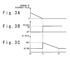
- Figs. 3A to 3C an operation of the controller 32 after trip of the turbine will be described.
- opening of a discharge valve is gradually decreased and at time t2, the discharge valve is fully closed.
- the time corresponds to time t11 in Fig. 2D .
- the controller 32 generates a trigger indicating that the discharge valve 30 is fully closed and sends the trigger to the control part 24.
- the trigger may be generated when the opening of the discharge valve 30 represents a predetermined value or less.
- the low-pressure side controller 27 is set to a manual operation and a set value is automatically set to a trip time low-pressure side pressure set value which is larger than the value in the normal control. Specifically, the control part 24 sets the SV value of the low-pressure side controller 27 to a plant value (MP2 in Fig. 3C ) of the steam pressure in the low-pressure header 6 at that time. After time t2, the control part 24 lowers the SV value of the low-pressure side controller 27 at a predetermined change rate to the SV value of 48.5 KG in the normal control at time t5.
- Figs. 4A to 4D show a course of events in a state of the plant following this state.
- the steam flow F5 starts to increase at time t1.
- the controller 32 decreases the opening of the discharge valve 30 and the steam flow F4 gradually decreases.
- the discharge valve 30 is fully closed.
- the trigger is turned ON and the SV value of the low-pressure side controller 27 is set from 48.5 KG in the normal control to the steampressure in the low-pressure header 6 at time t2 (52 KG in Fig. 4C ) .
- This SV value (trip time low-pressure side pressure set value) decreases to the SV value in the normal control at a predetermined change rate.
- Figs. 4A to 4D show the time as t3.
- the low-pressure side controller 27 After time t3, the low-pressure side controller 27 generates an opening instruction MV value so as to increase the opening of the turbine bypass valve 23.
- the control part 24 performs control so as to increase the opening of the turbine bypass valve 23 in a short period of time after the discharge valve 30 is closed.
- the steam pressure in the high-pressure header 4 decreases.
- the steam pressure in the high-pressure header 4 falls below the SV value of the controller 15 of the auxiliary boiler system.
- the controller 15 increases opening of the auxiliary boiler steam flow control valve 14 and thus, the steam flow F2 increases.
- steam of the auxiliary boiler 13 is supplied to the high-pressure header 4 in a short period of time after the discharge valve 30 is fully closed.
- Fig. 4A the abnormal drop of the steam pressure in the high-pressure header 4 is avoided.
- hunting of the steam pressure is also suppressed.
- the steam flow F3 of the turbine bypass line 22 smoothly increases in a short period of time after the discharge valve 30 is fully closed.
- a low-pressure side set value of the turbine bypass valve 23 is set to be larger one. For this setting, since additional steam is supplied to the low-pressure header 6 before the steam pressure in the low-pressure header 6 substantially decreases, the abnormal drop of the steampressure is avoided. As a result, stability of control after trip of the turbine is enhanced.
- the after-trip control is started.
- the controller 32 of the discharge valve 30 performs control to generate the trigger at timing when the steam pressure in the low-pressure header 6 decreases relative to the SV value (52 KG) of the controller 32 by a predetermined width, thereby achieving a similar effect.
Landscapes
- Engineering & Computer Science (AREA)
- Mechanical Engineering (AREA)
- General Engineering & Computer Science (AREA)
- Chemical & Material Sciences (AREA)
- Combustion & Propulsion (AREA)
- Control Of Turbines (AREA)
- Control Of Steam Boilers And Waste-Gas Boilers (AREA)
Abstract
Description
- The present invention relates to a control of a steam system. This application is based on Japanese Patent Application No.
2007-036825 filed on February 16, 2007 - In chemical plants such as a methanol plant and an ammonia plant (a urea plant is included), high-temperature and high-pressure steam is used.
Fig. 1 shows an example of a steam system for controlling the steam. - The
steam system 2 has a high-pressure header 4 which stores high-pressure steam therein and a low-pressure header 6 which stores low-pressure steam whose pressure is lower than that of the high-pressure steam. In some plants, a header corresponding to the low-pressure header 6 inFig. 1 may be referred to as a medium-pressure header. - The high-
pressure header 4 is connected to a waste-heat boiler 8. The waste-heat boiler 8 supplies high-pressure steam to the high-pressure header 4. A supply system of the waste-heat boiler 8 has asafety valve 10 and adischarge valve 12. When a steam pressure of the supply system exceeds a first predetermined pressure, a controller of adischarge valve 12 gradually increases valve opening set to be fully closed in normal time to release steam to the outside of the system. When pressure of the supply system exceeds a second predetermined pressure set larger than the first predetermined pressure, thesafety valve 10 is opened depending on the steam pressure to release steam to the outside of the system. The high-pressure header 4 is further connected to anauxiliary boiler 14. Theauxiliary boiler 14 supplies high-pressure steam generated by the auxiliary boiler (package boiler) to the high-pressure header 4. Pressure of the steam supplied by the waste-heat boiler 8 is higher than pressure of the steam supplied by theauxiliary boiler 14. - The low-
pressure header 6 has adischarge valve 30. When steam pressure in the low-pressure header 6 exceeds a predetermined discharge valve control start pressure, acontroller 32 of thedischarge valve 30 gradually increases the valve opening set to be fully closed in normal time to release steam to the outside of the system. This control is performed by means of a PI controller using a difference between a measurement value PV of the steam pressure in the low-pressure header 6 and a discharge valve MV set to be slightly larger than a target value of the steam pressure in the low-pressure header in normal time. A pressure set value of thecontroller 32 of thedischarge valve 30 is larger than a pressure set value of a low-pressure side controller 27 of aturbine bypass valve 23 described later. - The low-
pressure header 6 further has asafety valve 28. When a steam pressure exceeds a safety valve control s.tart pressure set to be larger than the discharge valve control start pressure, thesafety valve 28 is opened depending on the steam pressure to release steam to the outside of the system. The low-pressure header 6 further supplies low-pressure steam to anotherprocess 34. - The high-
pressure header 4 is connected to aturbine 16. High-pressure steam in the high-pressure header 4 is introduced into theturbine 16 through aturbine inlet piping 18. Theturbine 16 is driven by the high-pressure steam, supplies mechanical energy to external apparatuses not shown and discharges steam with lower pressure. Apart of the discharged steam is supplied to the low-pressure header 6 through aturbine outlet piping 20. Another part of the steam is supplied to a condenser not shown and the like. - The
steam system 2 further has aturbine bypass line 22 connecting the high-pressure header 4 to the low-pressure header 6. Theturbine bypass line 22 has theturbine bypass valve 23 for controlling a flow of steam flowing therein. When theturbine bypass valve 23 is opened, high-pressure steam in the high-pressure header 4 bypasses theturbine 16 and is supplied to the low-pressure header 6 through theturbine bypass line 22. - The
turbine bypass valve 23 is controlled by operating a solenoid according to a control signal sent from acontrol part 24. Thecontrol part 24 has a high-pressure side controller 25, a low-pressure side controller 27 and a higher-order selector 26. - The high-
pressure side controller 25 receives an input of a high-pressure side pressure being a plant value obtained by measuring pressure of the high-pressure steam in the high-pressure header 4. Based on a pre-stored process, the high-pressure side controller 25 generates high-pressure side MV for instructing opening of theturbine bypass valve 23 from the input high-pressure side pressure and outputs the high-pressure side MV. The high-pressure side MV is generated, for example, according to a PI control based on the difference between the high-pressure side pressure and the high-pressure side pressure set value. The pressure set value of the high-pressure side controller 25 is smaller than the pressure of the steam supplied by the waste-heat boiler 8 and is larger than the pressure of the steam supplied by anauxiliary boiler 13. - The low-
pressure side controller 27 receives an input of low-pressure side pressure being a plant value obtained by measuring pressure of the low-pressure steam in the low-pressure header 6. Based on a pre-s tored process, the low-pressure side controller 27 generates the low-pressure side MV for instructing the opening of theturbine bypass valve 23 from the input low-pressure side pressure. The low-pressure side MV is generated, for example, according to a PI control based on the difference between the low-pressure side pressure and the low-pressure side pressure set value. - The higher-
order selector 26 receives inputs of the high-pressure side MV and the low-pressure side MV, selects the larger value of them as MV for control, controls theturbine bypass valve 23 and sends steam of controlled amount from the high-pressure header 4 to the low-pressure header 6. According to such control, when steam pressure in the high-pressure header 4 becomes higher than a predetermined level, the steam pressure in the high-pressure header 4 can be decreased. Furthermore, when steam pressure in the low-pressure header 6 becomes lower than a predetermined level, the steam pressure in the low-pressure header 6 can be increased. - The low-
pressure header 6 is further connected to a low-pressure steam supply system not shown. The low-pressure steam supply system supplies low-pressure steam to the low-pressure header 6. The low-pressure steam supply system is controlled by a control device which previously stores a low-pressure side flow control SV therein. When pressure in the low-pressure header 6 exceeds the low-pressure side flow control SV, the amount of steam supplied from the low-pressure steam supply system to the low-pressure header 6 is decreased. - Japanese Laid-Open Patent Application
JP-A-Heisei, 11-257018 - Japanese Laid-Open Patent Application
JP-A-Heisei, 7-229405 - The inventors of this application found that instability in control as described below could occur in the above-mentioned steam system. The
turbine 16 may be tripped during a period when thesteam system 2 is operated. In the state where theturbine 16 is tripped, the amount of steam consumed by anotherprocess 34 may be increased and steam flow F5 supplied from the low-pressure header 6 to anotherprocess 34 may be increased. - When the
turbine 16 is tripped, the bypass valve is rapidly opened by the above-mentioned control, and temporarily, pressure in the high-pressure header 4 is rapidly decreased and pressure in the low-pressure header is rapidly increased. After that, since steam is discharged from thedischarge valve 30 to the outside, the pressure in the low-pressure header 6 lowers to 52 KG (kg/cm2G) or less once and gradually increases toward 52 KG. Since thecontrol part 24 decreases the opening of theturbine bypass valve 23, the pressure in the high-pressure header 4 gradually comes close to 107 KG. -
Figs. 2A to 2D show shift of a state of the plant after the above-mentioned state. InFig. 2D , it is assumed that, before time t10, the steam flow F5 supplied to anotherprocess 34 is smaller than the steam flow F1 supplied from the waste-heat boiler 8 to the high-pressure header 1. At time t10, the steam flow F5 starts to increase. - Since the waste-
heat boiler 8 generates steam by utilizing waste heat of an external system, the steam flow F1 supplied from the waste-heat boiler 8 to the high-pressure header 4 is substantially determined depending on conditions of the external system and cannot be flexibly controlled. As a result, at trip of the turbine, a steam flow F3 supplied from the high-pressure header 4 to the low-pressure header 6 does not increase and the steam flow F5 increases. - Accordingly, after time t10, the steam pressure in the low-
pressure header 6 tends to decrease. Since the difference between the PV value and the SV value becomes large, thecontroller 32 of thedischarge valve 30 generates a MV value as to decreases the opening of thedischarge valve 30. Thus, the opening of thedischarge valve 30 is gradually decreased and the decrease of the steam pressure in the low-pressure header 6 is suppressed. - At time t11, the
discharge valve 30 is fully closed. As shown inFig. 2C , after time t11, the steam pressure in the low-pressure header 6 lowers from the SV value of 52 KG of thecontroller 32. At time t12, the steam pressure represents the SV value of 48.5 KG of the low-pressure side controller 27 ofcontrol part 24 and is further reduced. - After time t12, the low-
pressure side controller 27 generates an MV value as to increase the opening of theturbine bypass valve 23 and sends the MV value to the higher-order selector 26. As shown inFig. 2A , however, at this time, the pressure in the high-pressure header 4 is high (107 KG). For this reason, the high-pressure side controller 24 generates the MV value so as to decrease the opening of theturbine bypass valve 23 and sends the MV value to the higher-order selector 26. For some time after time t11, the higher-order selector 26 selects the MV value of the high-pressure side controller 24 and uses the selected MV value to control theturbine bypass valve 23. The opening of theturbine bypass valve 23 is decreased and the pressure in the low-pressure header 6 is further decreased. The pressure in the low-pressure header 6 is abnormally decreased. This phenomenon is not preferred in terms of stability of operation of thesteam system 2. - When the pressure in the low-
pressure header 6 decreases beyond a certain extent, the MV value of the low-pressure side controller 27 becomes large and the higher-order selector 26 selects the MV value of the low-pressure side controller 27 as a control signal. The opening of theturbine bypass valve 23 decreases before this time, but increases after this time. As shown inFig. 2D , the steam flow F3 of theturbine bypass line 22 increases and the steam pressure in the low-pressure header 6 also increases. However, since the steam pressure abnormally decreases once, relatively large hunting can occur. - When the steam flow F3 becomes large, the steam pressure in the high-
pressure header 4 decreases. At time t13, when the steam pressure falls below the SV value of 105 KG of thecontroller 15 of theauxiliary boiler 13, as shown inFig. 2B , a flow F2 of the steam supplied from theauxiliary boiler 13 to the high-pressure header 4 increases. - However, the
auxiliary boiler 13 may have no readiness for offsetting the variation in pressure in the high-pressure header 4. In this case, as shown inFig. 2A , there is possibility that the pressure in the high-pressure header 4 abnormally decreases. Inaddition, relatively large hunting can occur by the time when the pressure in the high-pressure header 4 returns to a normal state. - Such instability can occur at times other than at trip of the turbine. In a state where the steam pressure in the low-
pressure header 6 is controlled by the opening of thedischarge valve 30, when the steam flow F5 supplied to anotherprocess 34 increases, the steam pressure in the low-pressure header 6 decreases. In such case, if pressure drop does not stop even when thedischarge valve 30 is fully closed, theturbine bypass valve 23 is opened and steam is supplied to the low-pressure header 6 according to a control of the opening. Also in this case, the unstable behavior can occur as in the above-mentioned trip of the turbine. - Then, an object of the present invention is to enhance stability of control of the steam system at trip of the turbine.
- A steam system according to the present invention includes: a high-pressure header configured to store high-pressure steam; a turbine configured to be driven by the high-pressure steam supplied from the high-pressure header; a low-pressure header configured to store steam discharged from the turbine as low-pressure steam; a discharge valve configured to discharge the low-pressure steam to outside of the low-pressure header; a discharge valve controller configured to control an opening of the discharge valve such that a pressure of the low-pressure steam decreases when a pressure of the low-pressure steam is larger than a discharge valve pressure set value; a bypass configured to introduce steam from the high-pressure header to the low-pressure header by bypassing the turbine; a bypass valve configured to control steam flow in the bypass; a bypass valve controller configured to perform a normal control in which an opening of the bypass valve is controlled based on a plant value of a pressure of the low-pressure steam when the turbine is driven; and a trip time control section configured to perform a trip time control in which steam is supplied from the high-pressure header to the low-pressure header by bypassing the turbine in response to a trip signal indicating that the turbine trips. The bypass valve controller performs an after-trip control in which an opening of the bypass valve is controlled to be larger than in the normal control after the trip time control and when the turbine is tripped.
- In a steam system according to the present invention, the bypass valve controller starts the after-trip control when an opening of the discharge valve becomes lower than a predetermined value.
- In a steam system according to the present invention, the bypass valve controller starts the after-trip control when a steam pressure in the low-pressure header decreases more than a predetermined value relative to the discharge valve pressure set value.
- In a steam system according to the present invention, the bypass valve controller includes a low-pressure side bypass valve controller configured to generate a low-pressure side control value for controlling the bypass valve such that a plant value of a pressure of the low-pressure steam approaches to a low-pressure side pressure set value.
- In a steam system according to the present invention, the low-pressure side bypass valve controller generates the low-pressure side control value based on a difference between a plant value of a pressure of the low-pressure steam and the low-pressure side pressure set value.
- In a steam system according to the present invention, the low-pressure side pressure set value is smaller than the discharge valve pressure set value.
- In a steam system according to the present invention, the bypass valve controller further includes: a high-pressure side bypass valve controller configured to generate a high-pressure side control value for controlling the bypass valve such that a pressure of the high-pressure steam approaches to a high-pressure side pressure set value; and a selector configured to select a larger value among the low-pressure side control value and the high-pressure side control value as a control value for controlling an opening of the bypass valve in the normal control.
- A steam system according to the present invention further includes: a waste-heat boiler configured to supply steam of a first pressure to the high-pressure header; and an auxiliary boiler configured to supply steam of a second pressure smaller than the first pressure. The high-pressure side pressure set value is smaller than the first pressure and larger than the second pressure.
- In a steam system according to the present invention, the bypass valve controller sets the low-pressure side pressure set value to a trip time low-pressure side pressure set value being larger than the low-pressure side pressure set value in the normal control when the after-trip control is started.
- In a steam system according to the present invention, the trip time low-pressure side pressure set value is set to a plant value of the low-pressure steam when the after-trip control is started.
- In a steam system according to the present invention, the trip time low-pressure side pressure set value is set back to the low-pressure side pressure set value in the normal control at a predetermined change rate subsequent to a time when the after-trip control is started.
- In the steam system according to the present invention, the after-trip control is started at timing when a pressure of the low-pressure steam becomes lower than the trip time low-pressure side pressure set value.
- In a steam system according to the present invention, the after-trip control is performed by adding a surplus value gradually increasing to an opening instruction value of the bypass valve in the normal control.
- According to the present invention, stability of control of the steam system at trip of the turbine is enhanced.
-
-
Fig. 1 shows a configuration of a steam system; -
Figs. 2A to 2D show shift in a state of a plant after trip of a turbine; -
Figs. 3A to 3C show operations of a controller after trip of the turbine; and -
Figs. 4A to 4D show shift in a state of the plant after trip of the turbine. - Best modes for carrying out the present invention will be described referring to the accompanying drawings. A control device and a control method in the present embodiment are realized by adding functions for trip of a turbine to the
controller 32 of thedischarge valve 30 and thecontrol part 24 in thesteam system 2 described referring toFig. 1 . Hereinafter, the function added to thecontroller 32 will be described referring toFig. 1 . The control in a normal operation is the same as that described above and thus description thereof is omitted. - Referring to
Figs. 3A to 3C , an operation of thecontroller 32 after trip of the turbine will be described. As shown inFig. 3A , opening of a discharge valve is gradually decreased and at time t2, the discharge valve is fully closed. The time corresponds to time t11 inFig. 2D . At this time, thecontroller 32 generates a trigger indicating that thedischarge valve 30 is fully closed and sends the trigger to thecontrol part 24. Depending on conditions of the plant, the trigger may be generated when the opening of thedischarge valve 30 represents a predetermined value or less. - When the
control part 24 receives the trigger at time t2, an after-trip control is started. The low-pressure side controller 27 is set to a manual operation and a set value is automatically set to a trip time low-pressure side pressure set value which is larger than the value in the normal control. Specifically, thecontrol part 24 sets the SV value of the low-pressure side controller 27 to a plant value (MP2 inFig. 3C ) of the steam pressure in the low-pressure header 6 at that time. After time t2, thecontrol part 24 lowers the SV value of the low-pressure side controller 27 at a predetermined change rate to the SV value of 48.5 KG in the normal control at time t5. - Next, a course of events in a state of the steam system subjected to the above-mentioned control after trip of the turbine will be described. When the
turbine 16 is tripped, the bypass valve is rapidly opened according to the above-mentioned control, the pressure in the high-pressure header 4 rapidly decreases temporarily, and the pressure in the low-pressure header rapidly increases. After that, by opening thedischarge valve 30, the pressure in the low-pressure header 6 decreases to 52 KG or less once and then, gradually increases toward 52 KG. Since thecontrol part 24 controls to decrease the opening of theturbine bypass valve 23, the pressure in the high-pressure header 4 gradually comes close to 107 KG. -
Figs. 4A to 4D show a course of events in a state of the plant following this state. As described with regard to time t10 in Fig. 3D, the steam flow F5 starts to increase at time t1. Due to drop of the steam pressure along with the increase, thecontroller 32 decreases the opening of thedischarge valve 30 and the steam flow F4 gradually decreases. At time t2, thedischarge valve 30 is fully closed. - Referring to
Fig. 4C , when thedischarge valve 30 is fully closed at time t2, the trigger is turned ON and the SV value of the low-pressure side controller 27 is set from 48.5 KG in the normal control to the steampressure in the low-pressure header 6 at time t2 (52 KG inFig. 4C ) . This SV value (trip time low-pressure side pressure set value) decreases to the SV value in the normal control at a predetermined change rate. - Since the trip pressure set value is larger than the SV value in the normal control, after time t2, the steam pressure in the low-
pressure header 6 falls below the trip time low-pressure side pressure set value in a short period of time.Figs. 4A to 4D show the time as t3. After time t3, the low-pressure side controller 27 generates an opening instruction MV value so as to increase the opening of theturbine bypass valve 23. According to this control, thecontrol part 24 performs control so as to increase the opening of theturbine bypass valve 23 in a short period of time after thedischarge valve 30 is closed. - As a result, steam is quickly supplied to the low-
pressure header 6 and as shown inFig. 3C , the abnormal drop of the steam pressure in the low-pressure header 6 is avoided. Since the trip time low-pressure side pressure set value is gradually returned to the SV value in the normal control, hunting can be suppressed. - After time t3, the steam pressure in the high-
pressure header 4 decreases. At time t4, the steam pressure in the high-pressure header 4 falls below the SV value of thecontroller 15 of the auxiliary boiler system. Then, thecontroller 15 increases opening of the auxiliary boiler steamflow control valve 14 and thus, the steam flow F2 increases. According to this control, steam of theauxiliary boiler 13 is supplied to the high-pressure header 4 in a short period of time after thedischarge valve 30 is fully closed. As a result, as shown inFig. 4A , the abnormal drop of the steam pressure in the high-pressure header 4 is avoided. Furthermore, hunting of the steam pressure is also suppressed. For this reason, as shown inFig. 4B , the steam flow F3 of theturbine bypass line 22 smoothly increases in a short period of time after thedischarge valve 30 is fully closed. - As described above, in the present embodiment, when the
discharge valve 30 is fully closed and the pressure in the low-pressure header 6 cannot be controlled by thedischarge valve 30, a low-pressure side set value of theturbine bypass valve 23 is set to be larger one. For this setting, since additional steam is supplied to the low-pressure header 6 before the steam pressure in the low-pressure header 6 substantially decreases, the abnormal drop of the steampressure is avoided. As a result, stability of control after trip of the turbine is enhanced. - In the present embodiment, using full closure of the
discharge valve 30 as the trigger, the after-trip control is started. In place of such control, thecontroller 32 of thedischarge valve 30 performs control to generate the trigger at timing when the steam pressure in the low-pressure header 6 decreases relative to the SV value (52 KG) of thecontroller 32 by a predetermined width, thereby achieving a similar effect. - By adoptingmeans other than the present embodiment, as to control after generation of the trigger, it is also possible to increase the steam flow F3 of the
turbine bypass line 22. For example, by adding an adder which adds a surplus value gradually increasing in a ramp manner to an opening instruction value output by theselector 26 during a predetermined period subsequent to an occurrence of the trigger and controlling theturbine bypass valve 23 according to the output of the adder, the steam flow F3 can be increased to achieve the same effect as in the present embodiment.
Claims (15)
- A steam system comprising:a high-pressure header configured to store high-pressure steam;a turbine configured to be driven by the high-pressure steam supplied from the high-pressure header;a low-pressure header configured to store steam discharged from the turbine as low-pressure steam;a discharge valve configured to discharge the low-pressure steam to outside of the low-pressure header;a discharge valve controller configured to control an opening of the discharge valve such that a pressure of the low-pressure steam decreases when a pressure of the low-pressure steam is larger than a discharge valve pressure set value;a bypass configured to introduce steam from the high-pressure header to the low-pressure header by bypassing the turbine;a bypass valve configured to control steam flow in the bypass;a bypass valve controller configured to perform a normal control in which an opening of the bypass valve is controlled based on a plant value of a pressure of the low-pressure steam when the turbine is driven; anda trip time control section configured to perform a trip time control in which steam is supplied from the high-pressure header to the low-pressure header by bypassing the turbine in response to a trip signal indicating that the turbine trips,wherein the bypass valve controller performs an after-trip control in which an opening of the bypass valve is controlled to be larger than in the normal control after the trip time control and when the turbine is tripped.
- The steam system according to claim 1, wherein the bypass valve controller starts the after-trip control when an opening of the discharge valve becomes lower than a predetermined value.
- The steam system according to claim 1, wherein the bypass valve controller starts the after-trip control when a steam pressure in the low-pressure header decreases more than a predetermined value relative to the discharge valve pressure set value.
- The steam system according to any of claims 1 to 3, wherein the bypass valve controller comprises a low-pressure side bypass valve controller configured to generate a low-pressure side control value for controlling the bypass valve such that a plant value of a pressure of the low-pressure steam approaches to a low-pressure side pressure set value.
- The steam system according to claim 4, wherein the low-pressure side bypass valve controller generates the low-pressure side control value based on a difference between a plant value of a pressure of the low-pressure steam and the low-pressure side pressure set value.
- The steam system according to claim 4 or 5, wherein the low-pressure side pressure set value is smaller than the discharge valve pressure set value.
- The steam system according to any of claims 4 to 6, wherein the bypass valve controller further comprises:a high-pressure side bypass valve controller configured to generate a high-pressure side control value for controlling the bypass valve such that a pressure of the high-pressure steam approaches to a high-pressure side pressure set value; anda selector configured to select a larger value among the low-pressure side control value and the high-pressure side control value as a control value for controlling an opening of the bypass valve in the normal control.
- The steam system according to claim 7, further comprising:a waste-heat boiler configured to supply steam of a first pressure to the high-pressure header; andan auxiliary boiler configured to supply steam of a second pressure smaller than the first pressure,wherein the high-pressure side pressure set value is smaller than the first pressure and larger than the second pressure.
- The steam system according to any of claims 4 to 8, wherein the bypass valve controller sets the low-pressure side pressure set value to a trip time low-pressure side pressure set value being larger than the low-pressure side pressure set value in the normal control when the after-trip control is started.
- The steam system according to claim 9, wherein the trip time low-pressure side pressure set value is set to a plant value of the low-pressure steam when the after-trip control is started.
- The steam system according to claim 10, wherein the trip time low-pressure side pressure set value is set back to the low-pressure side pressure set value in the normal control at a predetermined change rate subsequent to a time when the after-trip control is started.
- The steam system according to any of claims 9 to 11, wherein the after-trip control is started at timing when a pressure of the low-pressure steam becomes lower than the trip time low-pressure side pressure set value.
- The steam system according to any of claims 1 to 8, wherein the after-trip control is performed by adding a surplus value gradually increasing to an opening instruction value of the bypass valve in the normal control.
- A control system for a steam system comprising:a discharge valve controller configured to control an opening of a discharge valve for discharging low-pressure steam to outside of a low-pressure header such that a pressure of the low-pressure steam stored in the low-pressure header decreases when a pressure of the low-pressure steam is larger than a discharge valve pressure set value;a bypass valve controller configured to perform a normal control in which an opening of a bypass valve for controlling steam flow in a bypass for introducing steam from a high-pressure header storing a high-pressure steam to the low-pressure header by bypassing a turbine driven by the high-pressure steam supplied from the high-pressure header; anda trip time control section configured to perform a trip time control in which steam is supplied from the high-pressure header to the low-pressure header by bypassing the turbine in response to a trip signal indicating that the turbine trips,wherein the bypass valve controller performs an after-trip control in which an opening of the bypass valve is controlled to be larger than in the normal control after the trip time control and when the turbine is tripped.
- A control method for a steam system comprising the steps of:a discharge valve control step of controlling an opening of a discharge valve for discharging low-pressure steam to outside of a low-pressure header such that a pressure of the low-pressure steam stored in the low-pressure header decreases when a pressure of the low-pressure steam is larger than a discharge valve pressure set value;a bypass valve control step of performing a normal control in which an opening of a bypass valve for controlling steam flow in a bypass for introducing steam from a high-pressure header storing a high-pressure steam to the low-pressure header by bypassing a turbine driven by the high-pressure steam supplied from the high-pressure header; anda trip time control step of performing a trip time control in which steam is supplied from the high-pressure header to the low-pressure header by bypassing the turbine in response to a trip signal indicating that the turbine trips,wherein the bypass valve control step comprises:performing an after-trip control in which an opening of the bypass valve is controlled to be larger than in the normal control after the trip time control and when the turbine is tripped.
Applications Claiming Priority (2)
| Application Number | Priority Date | Filing Date | Title |
|---|---|---|---|
| JP2007036825A JP4616847B2 (en) | 2007-02-16 | 2007-02-16 | Steam system and control system and control method thereof |
| PCT/JP2008/052457 WO2008099894A1 (en) | 2007-02-16 | 2008-02-14 | Steam system, and its control system and control method |
Publications (3)
| Publication Number | Publication Date |
|---|---|
| EP2119879A1 true EP2119879A1 (en) | 2009-11-18 |
| EP2119879A4 EP2119879A4 (en) | 2010-04-07 |
| EP2119879B1 EP2119879B1 (en) | 2016-09-28 |
Family
ID=39690121
Family Applications (1)
| Application Number | Title | Priority Date | Filing Date |
|---|---|---|---|
| EP08711296.7A Not-in-force EP2119879B1 (en) | 2007-02-16 | 2008-02-14 | Steam system, and its control system and control method |
Country Status (6)
| Country | Link |
|---|---|
| US (1) | US8656718B2 (en) |
| EP (1) | EP2119879B1 (en) |
| JP (1) | JP4616847B2 (en) |
| AU (1) | AU2008215418B2 (en) |
| DK (1) | DK2119879T3 (en) |
| WO (1) | WO2008099894A1 (en) |
Cited By (1)
| Publication number | Priority date | Publication date | Assignee | Title |
|---|---|---|---|---|
| CN111255536A (en) * | 2020-01-22 | 2020-06-09 | 中国能源建设集团广东省电力设计研究院有限公司 | FCB operation method of gas-steam unit power plant |
Families Citing this family (12)
| Publication number | Priority date | Publication date | Assignee | Title |
|---|---|---|---|---|
| JP4909294B2 (en) * | 2008-02-05 | 2012-04-04 | 三菱重工業株式会社 | Turbine bypass control device and control method |
| EP2208867A1 (en) * | 2008-08-25 | 2010-07-21 | Siemens Aktiengesellschaft | Method and device for regulating a steam power plant |
| JP4823297B2 (en) * | 2008-11-26 | 2011-11-24 | 三菱重工業株式会社 | Steam system and control method thereof |
| JP5656754B2 (en) * | 2011-06-17 | 2015-01-21 | 株式会社タクマ | Power generation facility for waste incinerator and control method thereof |
| JP5656753B2 (en) * | 2011-06-17 | 2015-01-21 | 株式会社タクマ | Power generation facility for waste incinerator and control method thereof |
| JP2013160093A (en) * | 2012-02-02 | 2013-08-19 | Toshiba Corp | Protection device for turbine exhaust chamber and condenser, and monitoring and control device for turbine exhaust chamber and condenser |
| US8925319B2 (en) * | 2012-08-17 | 2015-01-06 | General Electric Company | Steam flow control system |
| JP5397560B1 (en) * | 2013-04-05 | 2014-01-22 | 富士電機株式会社 | Method and apparatus for safe operation of extraction steam turbine power generation facility |
| CN108702107B (en) * | 2016-02-26 | 2020-06-23 | 株式会社国际电气 | Power generation system, management device, and substrate processing device |
| DE102016204214A1 (en) * | 2016-03-15 | 2017-09-21 | Man Diesel & Turbo Se | Method for operating a steam turbine |
| US10338576B2 (en) | 2016-05-17 | 2019-07-02 | General Electric Company | Intelligent management system for balance of plant |
| JP6702028B2 (en) * | 2016-06-29 | 2020-05-27 | 三菱ケミカル株式会社 | Method for producing aromatic carboxylic acid |
Family Cites Families (20)
| Publication number | Priority date | Publication date | Assignee | Title |
|---|---|---|---|---|
| US4330367A (en) | 1973-05-22 | 1982-05-18 | Combustion Engineering, Inc. | System and process for the control of a nuclear power system |
| US4455614A (en) * | 1973-09-21 | 1984-06-19 | Westinghouse Electric Corp. | Gas turbine and steam turbine combined cycle electric power generating plant having a coordinated and hybridized control system and an improved factory based method for making and testing combined cycle and other power plants and control systems therefor |
| ZA751143B (en) | 1974-03-16 | 1976-01-28 | Uhde Gmbh Friedrich | Control system for steam flowrate and steam pressure |
| US3894394A (en) * | 1974-04-22 | 1975-07-15 | Westinghouse Electric Corp | HTGR power plant hot reheat steam pressure control system |
| US4007596A (en) * | 1975-04-24 | 1977-02-15 | Westinghouse Electric Corporation | Dual turbine power plant and method of operating such plant, especially one having an HTGR steam supply |
| US4007595A (en) | 1975-09-30 | 1977-02-15 | Westinghouse Electric Corporation | Dual turbine power plant and a reheat steam bypass flow control system for use therein |
| JPS56159601A (en) | 1980-05-14 | 1981-12-09 | Ricoh Co Ltd | Lens cementing device |
| JPS585415A (en) | 1981-06-30 | 1983-01-12 | Toshiba Corp | Steam pressure controller for combined-cycle power plant |
| US4679399A (en) * | 1985-09-13 | 1987-07-14 | Elliott Turbomachinery Co., Inc. | Protection system for steam turbines including a superheat monitor |
| JPS6371505A (en) * | 1986-09-12 | 1988-03-31 | Nippon Kokan Kk <Nkk> | Control method for steam turbine generator |
| JP2509612B2 (en) * | 1987-03-31 | 1996-06-26 | 株式会社東芝 | Bypass controller |
| US4752697A (en) | 1987-04-10 | 1988-06-21 | International Cogeneration Corporation | Cogeneration system and method |
| US4975238A (en) | 1988-09-01 | 1990-12-04 | Mpr, Inc. | Control system for a nuclear steam power plant |
| US5133189A (en) | 1991-07-15 | 1992-07-28 | Westinghouse Electric Corp. | System and method for individually testing valves in a steam turbine trip control system |
| JPH07229405A (en) | 1994-02-21 | 1995-08-29 | Mitsubishi Heavy Ind Ltd | Method for controlling turbine bypass of combined plant |
| JPH11257018A (en) | 1998-03-13 | 1999-09-21 | Toshiba Corp | Steam turbine steam bypass device |
| EP1388643B1 (en) | 2002-08-09 | 2008-10-29 | Hitachi, Ltd. | Combined cycle plant |
| EP1659294B1 (en) | 2004-11-17 | 2017-01-11 | Mitsubishi Heavy Industries Compressor Corporation | Compressor control unit and gas turbine power plant including this unit |
| JP2007036825A (en) | 2005-07-28 | 2007-02-08 | Bunka Shutter Co Ltd | Transmitter |
| JP4745812B2 (en) | 2005-12-15 | 2011-08-10 | 三菱重工業株式会社 | Combined power generation system and method of operating combined power generation system |
-
2007
- 2007-02-16 JP JP2007036825A patent/JP4616847B2/en not_active Expired - Fee Related
-
2008
- 2008-02-14 EP EP08711296.7A patent/EP2119879B1/en not_active Not-in-force
- 2008-02-14 DK DK08711296.7T patent/DK2119879T3/en active
- 2008-02-14 WO PCT/JP2008/052457 patent/WO2008099894A1/en not_active Ceased
- 2008-02-14 AU AU2008215418A patent/AU2008215418B2/en not_active Ceased
- 2008-02-14 US US12/375,780 patent/US8656718B2/en not_active Expired - Fee Related
Cited By (2)
| Publication number | Priority date | Publication date | Assignee | Title |
|---|---|---|---|---|
| CN111255536A (en) * | 2020-01-22 | 2020-06-09 | 中国能源建设集团广东省电力设计研究院有限公司 | FCB operation method of gas-steam unit power plant |
| CN111255536B (en) * | 2020-01-22 | 2022-08-30 | 中国能源建设集团广东省电力设计研究院有限公司 | FCB operation method of gas-steam unit power plant |
Also Published As
| Publication number | Publication date |
|---|---|
| DK2119879T3 (en) | 2017-01-23 |
| JP2008202432A (en) | 2008-09-04 |
| EP2119879A4 (en) | 2010-04-07 |
| JP4616847B2 (en) | 2011-01-19 |
| US8656718B2 (en) | 2014-02-25 |
| EP2119879B1 (en) | 2016-09-28 |
| AU2008215418B2 (en) | 2011-02-03 |
| US20090288414A1 (en) | 2009-11-26 |
| WO2008099894A1 (en) | 2008-08-21 |
| AU2008215418A1 (en) | 2008-08-21 |
Similar Documents
| Publication | Publication Date | Title |
|---|---|---|
| US8656718B2 (en) | Steam system, control system thereof and control method thereof | |
| US8620483B2 (en) | Control method and control device of steam system | |
| US9593844B2 (en) | Method for operating a waste heat steam generator | |
| US6912855B2 (en) | Method for the primary control in a combined gas/steam turbine installation | |
| US11092332B2 (en) | Once-through evaporator systems | |
| JP4909294B2 (en) | Turbine bypass control device and control method | |
| US8857455B2 (en) | Method for regulating a valve | |
| KR101818021B1 (en) | Method for regulating a short-term power increase of a steam turbine | |
| US7827793B2 (en) | Power generation system | |
| US11092331B2 (en) | Once-through evaporator systems | |
| US11242987B2 (en) | Once-through evaporator systems | |
| JP2017129103A5 (en) | ||
| US11506378B2 (en) | Once-through evaporator systems | |
| JP2001021107A (en) | Deaerator pressure control method for boiler equipment | |
| JPH07293807A (en) | Method for controlling water feeding in boiler of multi-shaft type combined facility and water feeding control device |
Legal Events
| Date | Code | Title | Description |
|---|---|---|---|
| PUAI | Public reference made under article 153(3) epc to a published international application that has entered the european phase |
Free format text: ORIGINAL CODE: 0009012 |
|
| 17P | Request for examination filed |
Effective date: 20090120 |
|
| AK | Designated contracting states |
Kind code of ref document: A1 Designated state(s): AT BE BG CH CY CZ DE DK EE ES FI FR GB GR HR HU IE IS IT LI LT LU LV MC MT NL NO PL PT RO SE SI SK TR |
|
| DAX | Request for extension of the european patent (deleted) | ||
| RBV | Designated contracting states (corrected) |
Designated state(s): DE DK GB IT |
|
| A4 | Supplementary search report drawn up and despatched |
Effective date: 20100308 |
|
| RIC1 | Information provided on ipc code assigned before grant |
Ipc: F01K 13/02 20060101ALI20100302BHEP Ipc: F01K 7/38 20060101AFI20080902BHEP Ipc: F22B 1/18 20060101ALI20100302BHEP Ipc: F01D 21/00 20060101ALI20100302BHEP Ipc: F01D 21/16 20060101ALI20100302BHEP Ipc: F01K 1/18 20060101ALI20100302BHEP Ipc: F01D 21/20 20060101ALI20100302BHEP |
|
| RBV | Designated contracting states (corrected) |
Designated state(s): DE DK GB IT |
|
| GRAP | Despatch of communication of intention to grant a patent |
Free format text: ORIGINAL CODE: EPIDOSNIGR1 |
|
| RIC1 | Information provided on ipc code assigned before grant |
Ipc: F01K 7/38 20060101AFI20160408BHEP Ipc: F01K 13/02 20060101ALI20160408BHEP Ipc: F01D 21/16 20060101ALI20160408BHEP Ipc: F01K 1/18 20060101ALI20160408BHEP Ipc: F01D 21/00 20060101ALI20160408BHEP Ipc: F01D 21/20 20060101ALI20160408BHEP Ipc: F01D 17/08 20060101ALI20160408BHEP Ipc: F22B 1/18 20060101ALI20160408BHEP |
|
| INTG | Intention to grant announced |
Effective date: 20160503 |
|
| GRAS | Grant fee paid |
Free format text: ORIGINAL CODE: EPIDOSNIGR3 |
|
| GRAA | (expected) grant |
Free format text: ORIGINAL CODE: 0009210 |
|
| AK | Designated contracting states |
Kind code of ref document: B1 Designated state(s): DE DK GB IT |
|
| REG | Reference to a national code |
Ref country code: GB Ref legal event code: FG4D |
|
| REG | Reference to a national code |
Ref country code: DE Ref legal event code: R096 Ref document number: 602008046494 Country of ref document: DE |
|
| REG | Reference to a national code |
Ref country code: DK Ref legal event code: T3 Effective date: 20170117 |
|
| REG | Reference to a national code |
Ref country code: DE Ref legal event code: R097 Ref document number: 602008046494 Country of ref document: DE |
|
| PLBE | No opposition filed within time limit |
Free format text: ORIGINAL CODE: 0009261 |
|
| STAA | Information on the status of an ep patent application or granted ep patent |
Free format text: STATUS: NO OPPOSITION FILED WITHIN TIME LIMIT |
|
| 26N | No opposition filed |
Effective date: 20170629 |
|
| REG | Reference to a national code |
Ref country code: DE Ref legal event code: R082 Ref document number: 602008046494 Country of ref document: DE Representative=s name: HENKEL & PARTNER MBB PATENTANWALTSKANZLEI, REC, DE Ref country code: DE Ref legal event code: R082 Ref document number: 602008046494 Country of ref document: DE Representative=s name: PATENTANWAELTE HENKEL, BREUER & PARTNER MBB, DE Ref country code: DE Ref legal event code: R081 Ref document number: 602008046494 Country of ref document: DE Owner name: MITSUBISHI HEAVY INDUSTRIES ENGINEERING, LTD.,, JP Free format text: FORMER OWNER: MITSUBISHI HEAVY INDUSTRIES, LTD., TOKYO, JP |
|
| REG | Reference to a national code |
Ref country code: GB Ref legal event code: 732E Free format text: REGISTERED BETWEEN 20181018 AND 20181024 |
|
| PGFP | Annual fee paid to national office [announced via postgrant information from national office to epo] |
Ref country code: GB Payment date: 20221230 Year of fee payment: 16 |
|
| PGFP | Annual fee paid to national office [announced via postgrant information from national office to epo] |
Ref country code: DK Payment date: 20230213 Year of fee payment: 16 |
|
| PGFP | Annual fee paid to national office [announced via postgrant information from national office to epo] |
Ref country code: IT Payment date: 20230110 Year of fee payment: 16 Ref country code: DE Payment date: 20221229 Year of fee payment: 16 |
|
| REG | Reference to a national code |
Ref country code: DE Ref legal event code: R119 Ref document number: 602008046494 Country of ref document: DE |
|
| REG | Reference to a national code |
Ref country code: DK Ref legal event code: EBP Effective date: 20240229 |
|
| GBPC | Gb: european patent ceased through non-payment of renewal fee |
Effective date: 20240214 |
|
| PG25 | Lapsed in a contracting state [announced via postgrant information from national office to epo] |
Ref country code: DE Free format text: LAPSE BECAUSE OF NON-PAYMENT OF DUE FEES Effective date: 20240903 |
|
| PG25 | Lapsed in a contracting state [announced via postgrant information from national office to epo] |
Ref country code: DK Free format text: LAPSE BECAUSE OF NON-PAYMENT OF DUE FEES Effective date: 20240229 |
|
| PG25 | Lapsed in a contracting state [announced via postgrant information from national office to epo] |
Ref country code: GB Free format text: LAPSE BECAUSE OF NON-PAYMENT OF DUE FEES Effective date: 20240214 |
|
| PG25 | Lapsed in a contracting state [announced via postgrant information from national office to epo] |
Ref country code: GB Free format text: LAPSE BECAUSE OF NON-PAYMENT OF DUE FEES Effective date: 20240214 Ref country code: DK Free format text: LAPSE BECAUSE OF NON-PAYMENT OF DUE FEES Effective date: 20240229 Ref country code: DE Free format text: LAPSE BECAUSE OF NON-PAYMENT OF DUE FEES Effective date: 20240903 |
|
| PG25 | Lapsed in a contracting state [announced via postgrant information from national office to epo] |
Ref country code: IT Free format text: LAPSE BECAUSE OF NON-PAYMENT OF DUE FEES Effective date: 20240214 |