EP2119587A1 - Controller for motor, and vehicle - Google Patents
Controller for motor, and vehicle Download PDFInfo
- Publication number
- EP2119587A1 EP2119587A1 EP08711485A EP08711485A EP2119587A1 EP 2119587 A1 EP2119587 A1 EP 2119587A1 EP 08711485 A EP08711485 A EP 08711485A EP 08711485 A EP08711485 A EP 08711485A EP 2119587 A1 EP2119587 A1 EP 2119587A1
- Authority
- EP
- European Patent Office
- Prior art keywords
- short
- switch
- circuit failure
- polarity side
- circuit
- Prior art date
- Legal status (The legal status is an assumption and is not a legal conclusion. Google has not performed a legal analysis and makes no representation as to the accuracy of the status listed.)
- Withdrawn
Links
Images



Classifications
-
- B—PERFORMING OPERATIONS; TRANSPORTING
- B60—VEHICLES IN GENERAL
- B60L—PROPULSION OF ELECTRICALLY-PROPELLED VEHICLES; SUPPLYING ELECTRIC POWER FOR AUXILIARY EQUIPMENT OF ELECTRICALLY-PROPELLED VEHICLES; ELECTRODYNAMIC BRAKE SYSTEMS FOR VEHICLES IN GENERAL; MAGNETIC SUSPENSION OR LEVITATION FOR VEHICLES; MONITORING OPERATING VARIABLES OF ELECTRICALLY-PROPELLED VEHICLES; ELECTRIC SAFETY DEVICES FOR ELECTRICALLY-PROPELLED VEHICLES
- B60L3/00—Electric devices on electrically-propelled vehicles for safety purposes; Monitoring operating variables, e.g. speed, deceleration or energy consumption
- B60L3/0023—Detecting, eliminating, remedying or compensating for drive train abnormalities, e.g. failures within the drive train
- B60L3/003—Detecting, eliminating, remedying or compensating for drive train abnormalities, e.g. failures within the drive train relating to inverters
-
- B—PERFORMING OPERATIONS; TRANSPORTING
- B60—VEHICLES IN GENERAL
- B60L—PROPULSION OF ELECTRICALLY-PROPELLED VEHICLES; SUPPLYING ELECTRIC POWER FOR AUXILIARY EQUIPMENT OF ELECTRICALLY-PROPELLED VEHICLES; ELECTRODYNAMIC BRAKE SYSTEMS FOR VEHICLES IN GENERAL; MAGNETIC SUSPENSION OR LEVITATION FOR VEHICLES; MONITORING OPERATING VARIABLES OF ELECTRICALLY-PROPELLED VEHICLES; ELECTRIC SAFETY DEVICES FOR ELECTRICALLY-PROPELLED VEHICLES
- B60L3/00—Electric devices on electrically-propelled vehicles for safety purposes; Monitoring operating variables, e.g. speed, deceleration or energy consumption
- B60L3/0023—Detecting, eliminating, remedying or compensating for drive train abnormalities, e.g. failures within the drive train
- B60L3/0069—Detecting, eliminating, remedying or compensating for drive train abnormalities, e.g. failures within the drive train relating to the isolation, e.g. ground fault or leak current
-
- B—PERFORMING OPERATIONS; TRANSPORTING
- B60—VEHICLES IN GENERAL
- B60L—PROPULSION OF ELECTRICALLY-PROPELLED VEHICLES; SUPPLYING ELECTRIC POWER FOR AUXILIARY EQUIPMENT OF ELECTRICALLY-PROPELLED VEHICLES; ELECTRODYNAMIC BRAKE SYSTEMS FOR VEHICLES IN GENERAL; MAGNETIC SUSPENSION OR LEVITATION FOR VEHICLES; MONITORING OPERATING VARIABLES OF ELECTRICALLY-PROPELLED VEHICLES; ELECTRIC SAFETY DEVICES FOR ELECTRICALLY-PROPELLED VEHICLES
- B60L3/00—Electric devices on electrically-propelled vehicles for safety purposes; Monitoring operating variables, e.g. speed, deceleration or energy consumption
- B60L3/04—Cutting off the power supply under fault conditions
-
- B—PERFORMING OPERATIONS; TRANSPORTING
- B60—VEHICLES IN GENERAL
- B60L—PROPULSION OF ELECTRICALLY-PROPELLED VEHICLES; SUPPLYING ELECTRIC POWER FOR AUXILIARY EQUIPMENT OF ELECTRICALLY-PROPELLED VEHICLES; ELECTRODYNAMIC BRAKE SYSTEMS FOR VEHICLES IN GENERAL; MAGNETIC SUSPENSION OR LEVITATION FOR VEHICLES; MONITORING OPERATING VARIABLES OF ELECTRICALLY-PROPELLED VEHICLES; ELECTRIC SAFETY DEVICES FOR ELECTRICALLY-PROPELLED VEHICLES
- B60L50/00—Electric propulsion with power supplied within the vehicle
- B60L50/50—Electric propulsion with power supplied within the vehicle using propulsion power supplied by batteries or fuel cells
- B60L50/51—Electric propulsion with power supplied within the vehicle using propulsion power supplied by batteries or fuel cells characterised by AC-motors
-
- H—ELECTRICITY
- H02—GENERATION; CONVERSION OR DISTRIBUTION OF ELECTRIC POWER
- H02P—CONTROL OR REGULATION OF ELECTRIC MOTORS, ELECTRIC GENERATORS OR DYNAMO-ELECTRIC CONVERTERS; CONTROLLING TRANSFORMERS, REACTORS OR CHOKE COILS
- H02P29/00—Arrangements for regulating or controlling electric motors, appropriate for both AC and DC motors
- H02P29/02—Providing protection against overload without automatic interruption of supply
- H02P29/032—Preventing damage to the motor, e.g. setting individual current limits for different drive conditions
-
- G—PHYSICS
- G01—MEASURING; TESTING
- G01R—MEASURING ELECTRIC VARIABLES; MEASURING MAGNETIC VARIABLES
- G01R31/00—Arrangements for testing electric properties; Arrangements for locating electric faults; Arrangements for electrical testing characterised by what is being tested not provided for elsewhere
- G01R31/40—Testing power supplies
- G01R31/42—AC power supplies
-
- G—PHYSICS
- G01—MEASURING; TESTING
- G01R—MEASURING ELECTRIC VARIABLES; MEASURING MAGNETIC VARIABLES
- G01R31/00—Arrangements for testing electric properties; Arrangements for locating electric faults; Arrangements for electrical testing characterised by what is being tested not provided for elsewhere
- G01R31/50—Testing of electric apparatus, lines, cables or components for short-circuits, continuity, leakage current or incorrect line connections
- G01R31/52—Testing for short-circuits, leakage current or ground faults
-
- H—ELECTRICITY
- H10—SEMICONDUCTOR DEVICES; ELECTRIC SOLID-STATE DEVICES NOT OTHERWISE PROVIDED FOR
- H10W—GENERIC PACKAGES, INTERCONNECTIONS, CONNECTORS OR OTHER CONSTRUCTIONAL DETAILS OF DEVICES COVERED BY CLASS H10
- H10W72/00—Interconnections or connectors in packages
- H10W72/071—Connecting or disconnecting
- H10W72/073—Connecting or disconnecting of die-attach connectors
- H10W72/07331—Connecting techniques
- H10W72/07336—Soldering or alloying
-
- H—ELECTRICITY
- H10—SEMICONDUCTOR DEVICES; ELECTRIC SOLID-STATE DEVICES NOT OTHERWISE PROVIDED FOR
- H10W—GENERIC PACKAGES, INTERCONNECTIONS, CONNECTORS OR OTHER CONSTRUCTIONAL DETAILS OF DEVICES COVERED BY CLASS H10
- H10W72/00—Interconnections or connectors in packages
- H10W72/071—Connecting or disconnecting
- H10W72/076—Connecting or disconnecting of strap connectors
- H10W72/07631—Techniques
- H10W72/07636—Soldering or alloying
-
- H—ELECTRICITY
- H10—SEMICONDUCTOR DEVICES; ELECTRIC SOLID-STATE DEVICES NOT OTHERWISE PROVIDED FOR
- H10W—GENERIC PACKAGES, INTERCONNECTIONS, CONNECTORS OR OTHER CONSTRUCTIONAL DETAILS OF DEVICES COVERED BY CLASS H10
- H10W72/00—Interconnections or connectors in packages
- H10W72/60—Strap connectors, e.g. thick copper clips for grounding of power devices
- H10W72/651—Materials of strap connectors
- H10W72/652—Materials of strap connectors comprising metals or metalloids, e.g. silver
-
- H—ELECTRICITY
- H10—SEMICONDUCTOR DEVICES; ELECTRIC SOLID-STATE DEVICES NOT OTHERWISE PROVIDED FOR
- H10W—GENERIC PACKAGES, INTERCONNECTIONS, CONNECTORS OR OTHER CONSTRUCTIONAL DETAILS OF DEVICES COVERED BY CLASS H10
- H10W72/00—Interconnections or connectors in packages
- H10W72/60—Strap connectors, e.g. thick copper clips for grounding of power devices
- H10W72/651—Materials of strap connectors
- H10W72/655—Materials of strap connectors of outermost layers of multilayered strap connectors, e.g. material of a coating
-
- H—ELECTRICITY
- H10—SEMICONDUCTOR DEVICES; ELECTRIC SOLID-STATE DEVICES NOT OTHERWISE PROVIDED FOR
- H10W—GENERIC PACKAGES, INTERCONNECTIONS, CONNECTORS OR OTHER CONSTRUCTIONAL DETAILS OF DEVICES COVERED BY CLASS H10
- H10W90/00—Package configurations
- H10W90/701—Package configurations characterised by the relative positions of pads or connectors relative to package parts
- H10W90/761—Package configurations characterised by the relative positions of pads or connectors relative to package parts of strap connectors
- H10W90/763—Package configurations characterised by the relative positions of pads or connectors relative to package parts of strap connectors between laterally-adjacent chips
-
- H—ELECTRICITY
- H10—SEMICONDUCTOR DEVICES; ELECTRIC SOLID-STATE DEVICES NOT OTHERWISE PROVIDED FOR
- H10W—GENERIC PACKAGES, INTERCONNECTIONS, CONNECTORS OR OTHER CONSTRUCTIONAL DETAILS OF DEVICES COVERED BY CLASS H10
- H10W90/00—Package configurations
- H10W90/701—Package configurations characterised by the relative positions of pads or connectors relative to package parts
- H10W90/761—Package configurations characterised by the relative positions of pads or connectors relative to package parts of strap connectors
- H10W90/764—Package configurations characterised by the relative positions of pads or connectors relative to package parts of strap connectors between a chip and a stacked insulating package substrate, interposer or RDL
-
- Y—GENERAL TAGGING OF NEW TECHNOLOGICAL DEVELOPMENTS; GENERAL TAGGING OF CROSS-SECTIONAL TECHNOLOGIES SPANNING OVER SEVERAL SECTIONS OF THE IPC; TECHNICAL SUBJECTS COVERED BY FORMER USPC CROSS-REFERENCE ART COLLECTIONS [XRACs] AND DIGESTS
- Y02—TECHNOLOGIES OR APPLICATIONS FOR MITIGATION OR ADAPTATION AGAINST CLIMATE CHANGE
- Y02T—CLIMATE CHANGE MITIGATION TECHNOLOGIES RELATED TO TRANSPORTATION
- Y02T10/00—Road transport of goods or passengers
- Y02T10/60—Other road transportation technologies with climate change mitigation effect
- Y02T10/64—Electric machine technologies in electromobility
-
- Y—GENERAL TAGGING OF NEW TECHNOLOGICAL DEVELOPMENTS; GENERAL TAGGING OF CROSS-SECTIONAL TECHNOLOGIES SPANNING OVER SEVERAL SECTIONS OF THE IPC; TECHNICAL SUBJECTS COVERED BY FORMER USPC CROSS-REFERENCE ART COLLECTIONS [XRACs] AND DIGESTS
- Y02—TECHNOLOGIES OR APPLICATIONS FOR MITIGATION OR ADAPTATION AGAINST CLIMATE CHANGE
- Y02T—CLIMATE CHANGE MITIGATION TECHNOLOGIES RELATED TO TRANSPORTATION
- Y02T10/00—Road transport of goods or passengers
- Y02T10/60—Other road transportation technologies with climate change mitigation effect
- Y02T10/70—Energy storage systems for electromobility, e.g. batteries
Definitions
- the present invention relates to a controller for a motor used as a driving force generation element or the like for a vehicle, and a vehicle mounted with the motor.
- a motor having an armature of multiple phases such as a brushless direct-current motor of three phases, is mounted in a vehicle such as a hybrid vehicle or an electric vehicle and is used as a driving force generation element for the vehicle.
- the operation control of the motor is generally performed by supplying electric power from a capacitor such as a battery or the like through the intermediary of an inverter (PWM inverter) circuit of multiple phases to the motor (for example, refer to Japanese Patent Laid-open No. H9-46811 ).
- PWM inverter inverter
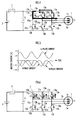
- the inverter circuit designated by a reference number 7 has a circuit configuration illustrated in Fig. 1 , for example.
- the inverter circuit 7 is constituted by connecting in parallel arms 10u, 10v and 10w of multiple phases (3 phases in the illustrated example).
- Each of the arms 10u, 10v and 10w is constituted by connecting in series a switch portion 13a disposed on a positive polarity side and a switch portion 13b disposed on a negative polarity side.
- the switch portion 13a is constituted by connecting a switch element 11a and a feedback diode 12a in parallel.
- the switch portion 13b is constituted by connecting a switch element 11b and a feedback diode 12b in parallel.
- a short-circuit failure may occur in either switch portion of the inverter circuit so that the switch portion is kept in a continual conducted state despite a control signal output to a switch element of the switch portion.
- the conducted state of a switch portion described in the present invention means that both terminals of the switch portion are substantially short-circuited and an electric current can flow in the switch portion in both directions.
- the conducted state of the switch portion is equivalent to the conducted state (ON state) of the switch element.
- a short-circuit failure state of the switch portion means that the switch element of the switch portion is switched on (conducted state) continuously despite a control signal output to the switch element, or a feedback diode is in the conducted state in both directions, namely, a forward direction and a backward direction thereof.
- the art disclosed in Japanese Patent Laid-open No. H9-46811 disposes a switch in a power distribution path between the capacity and the inverter circuit and a power distribution path between the inverter circuit and the motor. According thereto, when a short-circuit failure occurs in either switch portion of the inverter circuit, it is possible to prevent the electric current from flowing into each switch portion of the inverter circuit by, for example, shutting off the switches thereof.
- the present invention has been accomplished in view of the aforementioned problems, and it is therefore an object of the present invention to provide a controller for a motor capable of preventing a large electric current from flowing into each switch portion of an inverter circuit without the need of providing a switch or the like to block the power distribution between the motor and the inverter circuit when a short-circuit failure occurs in any of the switch portions of the inverter circuit during the operation of the motor by means of an appropriate ON/OFF control (conduction/ blockade control) on switch elements in the normal switch portions of the inverter circuit, and a vehicle.
- ON/OFF control conduction/ blockade control
- the controller for the motor of the present invention which is powered by a direct-current power source via a multi-phase inverter circuit composed of switch portions having switch elements and feedback diodes connected in parallel to the switch elements disposed at a positive polarity side and a negative polarity side of an arm of each phase, includes: a short-circuit failure detecting member configured to detect an occurrence of a short-circuit failure which causes any switch portion in the inverter circuit to be in a continual conducted state during the operation of the motor; a short-circuit failure polarity determining member configured to determine whether a short-circuit failure switch portion in which an occurrence of a short-circuit failure has been detected by the short-circuit failure detecting member is on the positive polarity side or on the negative polarity side; and a short-circuit failure controlling member configured to control each of the other switch elements except at least the switch element of the short-circuit failure switch portion among the switch portions in the inverter circuit in such a way that all
- the vehicle of the present invention which is provided with a motor as a driving force generating element, the motor being powered by a direct-current power source via a multi-phase inverter circuit composed of switch portions having switch elements and feedback diodes connected in parallel to the switch elements disposed at a positive polarity side and a negative polarity side of an arm of each phase, includes: a short-circuit failure detecting member configured to detect an occurrence of a short-circuit failure which causes any switch portion in the inverter circuit to be in a continual conducted state during the operation of the motor; a short-circuit failure polarity determining member configured to determine whether a short-circuit failure switch portion in which an occurrence of a short-circuit failure has been detected by the short-circuit failure detecting member is on the positive polarity side or on the negative polarity side; and a short-circuit failure controlling member configured to control each of the other switch elements except at least the switch element of the short-circuit failure switch portion among the switch portions in the inverter circuit
- the controller for the motor and the vehicle of the present invention when an occurrence of a short-circuit failure at any switch portion of the inverter circuit is detected by the short-circuit failure detecting member, whether the short-circuit failure switch portion where the short-circuit failure has occurred is on the positive polarity side (the so-called high side) or on the negative polarity side (the so-called low side)of the inverter circuit is determined by the short-circuit failure polarity determining member.
- each of the other switch elements except at least the switch element of the short-circuit failure switch portion among the switch portions in the inverter circuit is controlled by the short-circuit failure controlling member in such a way that all the switch portions on the same polarity side as the short-circuit failure switch portion determined by the short-circuit failure polarity determining member are set in a conducted state and all the switch elements of all the switch portions on the different polarity side from the short-circuit failure switch portion are set in a disconnected state.
- the short-circuit failure state of a short-circuit switch portion may be caused by a failure on a switch element of the short-circuit failure switch portion and a failure on a feedback diode. In either case, the short-circuit failure switch is kept in the conducted state despite the control on the switch element of the short-circuit failure switch portion. Therefore, it is not obligatory for the short-circuit failure controlling member to control the switch element of the short-circuit failure switch portion so that the switch element is in the conducted state, however, it is acceptable.
- the armature coils of each phase in the motor are brought into a mutual short-circuit state through the switch portions being in the conducted state.
- the conducted switch portions of each phase of the inverter circuit is flown with a phase current of a magnitude level substantially equal for each phase generated according to the rotation of an output shaft of the motor, the phase current will not be particularly large.
- the controller for the motor and the vehicle of the present invention it is possible to prevent a large electric current from flowing into each switch portion of the inverter circuit without the need of providing a switch or the like to block the power distribution between the motor and the inverter circuit when a short-circuit failure occurs in any of the switch portions of the inverter circuit during the operation of the motor by means of an appropriate ON/OFF control (conduction/ blockade control) on switch elements in the normal switch portions of the inverter circuit.
- ON/OFF control conduction/ blockade control
- the short-circuit failure polarity determining member can determine whether the short-circuit failure switch element is on the positive polarity side or on the negative polarity side according to what is mentioned below.
- the controller further includes a phase current detecting member configured to detect a phase current of each phase of the motor, wherein the short-circuit failure polarity determining member determines whether the short-circuit failure switch portion is on the positive polarity side or on the negative polarity side according to a direction of each phase current detected by the phase current detecting member after short-circuit failure polarity determining member has set a power source switch disposed in a power distribution path between the direct-current power source and the inverter circuit in the disconnected state and has output a control signal to all the switch elements in the inverter circuit to set the switch element in the disconnected state.
- a phase current detecting member configured to detect a phase current of each phase of the motor, wherein the short-circuit failure polarity determining member determines whether the short-circuit failure switch portion is on the positive polarity side or on the negative polarity side according to a direction of each phase current detected by the phase current detecting member after short-circuit failure polarity determining member has set a power source
- each phase current is of the same direction.
- each phase current in the case where the short-circuit failure switch portion is on the positive polarity side and each phase current in the case where the short-circuit failure switch portion is on the negative polarity side are of opposite directions. Accordingly, whether the short-circuit failure switch portion is on the positive polarity side or on the negative polarity side can be determined according to the direction of each phase current detected by the phase current detecting member.
- the short-circuit failure determining member can detect whether the short-circuit failure switch portion is on the positive polarity side or on the negative polarity side according to whether or not the occurrence of a short-circuit failure has been detected by the short-circuit failure detecting member after short-circuit failure polarity determining member maintains a power source switch disposed in a power distribution path between the direct-current power source and the inverter circuit in the conducted state, outputs a control signal to all the switch elements on any of the positive polarity side and the negative polarity side of the inverter circuit to set the switch elements in the conducted state and a control signal to all the switch elements on the other polarity side to set the switch elements in the disconnected state.
- an excess short-circuit current flows through the short-circuit failure switch portion and the switch portions connected thereto in series from the direct-current power source or a smoothing condenser generally disposed on the input side of the inverter circuit.
- the occurrence of a short-circuit failure can be detected by the short-circuit failure detecting member.
- a parallel connection of the switch element and the feedback diode in each switch portion a series connection of the switch portion on the positive polarity side and the switch portion on the negative polarity side, a connection of a pair of power source terminals and a series circuit of the switch portion on the positive polarity side and the switch portion on the negative polarity side, and a connection of an output terminal and a central point of the series circuit of the switch portion on the positive polarity side and the switch portion on the negative polarity side of each arm in the inverter circuit are conducted through a conductive plate member.
- Fig. 1 Illustrated in Fig. 1 is a circuit configuration of a controller of a motor in the first embodiment.
- the reference numeral 1 denotes a motor
- the reference numeral 2 denotes a capacitor used as a direct-current power source for the motor 1
- the reference numeral 3 denotes a power drive circuit unit (hereinafter, referred to as PDU) of the motor 1
- the reference numeral 4 denotes an electronic control unit (hereinafter, referred to as ECU) for performing an operation control on the motor 1 through the intermediary of the power drive circuit unit 3.
- ECU electronice control unit
- the motor 1 is a 3-phase brushless DC motor, for example.
- the motor 1 is mounted in a hybrid vehicle of a parallel type (not shown) as an auxiliary driving force generation element. It is also acceptable to mount the motor 1 in an electric vehicle or in a hybrid vehicle of a series type (not shown) as a driving force generation element.
- an output shaft (rotor) of the motor 1 is connected with an output shaft of an engine and a drive wheel of the vehicle through the intermediary of a transmission, a crutch or the like.
- the output shaft of the motor 1 is connected with a drive wheel of the vehicle through the intermediary of a transmission, a crutch or the like.
- the structure of the mentioned vehicle may be publicly known.
- the capacitor 2 is a secondary battery which can be charged and discharged.
- a positive pole of the capacitor 2 is connected with a power source terminal 3a on the positive polarity side of the PDU 3 through the intermediary of a contactor 5, and a negative pole thereof is connected with a power source terminal 3b on the negative polarity side of the PDU 3.
- the contactor 5 functions as a power source switch for the motor 1.
- the capacitor 2 is enabled to supply power to an inverter circuit 7 (to be described hereinafter) of the PDU 3.
- a high-capacity condenser such as a two-layered electric condenser or the like as the capacitor 2.
- It is also acceptable to use a direct-current power source capable of applying a direct-current voltage from the capacitor 2 to the PDU 3 through a bi-directional DC-DC convertor.
- the PDU 3 is provided with a smoothing condenser 6, the inverter circuit 7, a control unit 8 which controls the operation of the inverter circuit 7 according to an instruction issued from the ECU 4, and electric current sensors 9u, 9v, 9w which are used as electric current detecting members for detecting electric currents (phase currents) in armature coils 1u, 1v, 1w of each phase (U phase, V phase, and W phase) of the motor 1, respectively.
- the smoothing condenser 6 is connected between the power source terminals 3a and 3b. However, if two phase currents among the three are defined, the last phase current can be defined unambiguously, thus, either one of the electric current sensors 9u, 9v and 9w can be omitted.
- the inverter circuit 7 is a 3-phase inverter circuit constituted by connecting arms 10u, 10v, 10w of 3 phases corresponding to each phase of the motor 1, respectively, with the smoothing condenser 6 in parallel between the power source terminals 3a and 3b.
- Each of the arms 10u, 10v and 10w of the inverter circuit 7 is composed of a pair of switch elements 11a and 11b connected in series and a pair of feedback diodes 12a and 12b connected in parallel to the pair of the switch elements 11a and 11b, respectively.
- each of the arms 10u, 10v and 10w is constituted by connecting in series a switch portion 13a and a switch portion 13b.
- the switch portion 13a is constituted by connecting in parallel the switch element 11a and the feedback diode 12a
- the switch portion 13b is constituted by connecting in parallel the switch element 11b and the feedback diode 12b.
- each of the switch elements 11a and 11b is an IGBT (Insulated Gate Bipolar Transistor) and is switched on or off (conducted or disconnected) according to a control signal (a pulse signal) output to a gate thereof.
- a central point of each of the arms 10u, 10v and 10w (a point between the switch portions 13a and 13b) is connected with the U phase armature coil 1u, the V phase armature coil 1v and the W phase armature coil 1w of the motor 1 through the intermediary of the electric current sensors 9u, 9v and 9w, respectively.
- the IGBT included in each of the switch elements 11a and 11b in the present embodiment is a current sensitive IGBT having a function of detecting an electric current flowing between a collector and an emitter thereof (a function of outputting a detection signal in accordance with the electric current), and the detection signal thereof is configured to be input to the control unit 8.
- the switch element 11a and the switch element 11b may be referred to as the positive polarity side switch element 11a and the negative polarity side switch element 11b, respectively, where appropriate.
- the feedback diode 12a and the feedback diode 12b may be referred to as the positive polarity side feedback diode 12a and the feedback diode 12b, respectively, where appropriate;
- the switch element 13a and the switch element 13b may be referred to as the positive polarity side switch element 13a and the negative polarity side switch element 13b, respectively, where appropriate.
- each arm 10 is provided with a heat sink 14, an insulation sheet 15 and heat spreaders 16a and 16b.
- the heat spreaders 16a and 16b are mounted on the heat sink 14 without inter contact thereto with the insulation sheet 15 intervened therebetween.
- Each of the heat spreaders 16a and 16b is used as a conductive plate member in the present embodiment.
- the materials for the heat spreaders 16a and 16b may be copper, for example.
- a chip of the switch element (IGBT) 11a and a chip of the feedback diode 12a are fixed on an upper surface of the heat spreader 16a through a solder 17a.
- a chip of the switch element (IGBT) 11b and a chip of the feedback diode 12b are fixed on the upper surface of the heat spreader 16b through a solder 17b.
- the emitter of the switch element 11a and the anode of the feedback 12a are connected through the heat spreader 16a and are conducted to the heat spreader 16a.
- the emitter of the switch element 11b and the anode of the feedback 12b are connected through the heat spreader 16b.
- a plate-like connection portion 20 is integrally extended from the beam lead 18b toward the heat spreader 16a, and is conductively fixed to the heat spreader 16a by a screw or the like.
- ach arm 10 is provided with power source terminals 21a and 21b, and an output terminal 22.
- the power source terminals 21a and 21b are connected to the power source terminals 3a at the positive polarity side and the power source terminals 3b at the negative polarity side of the PDU 3, respectively.
- the output terminal 22 is connected to either of the armature coils 1u, 1v and 1w of one phase (corresponding to each of the arms 10u, 10v and 10w) of the motor 1.
- the power source terminal 21a is integrally formed at one end portion of the beam lead 18a.
- the power source terminal 21b is integrally formed at one end portion of a conductive plate member 23 which is conductively fixed at the heat spreader 16b through a screw or the like.
- the output terminal 22 is integrally formed at a portion extended from one side (the portion extended vertical to the paper in Fig. 2 ) of the beam lead 18b.
- the materials for the conductive member 23 may be copper, for example.
- the switch element 11a and the feedback diode 12a are connected in parallel through the heat spreader 16a serving as the conductive plate member and the beam lead 18a, and resultantly, to form the switch portion 13a.
- the switch element 11b and the feedback diode 12b are connected in parallel through the heat spreader 16b serving as the conductive plate member and the beam lead 18b, and resultantly, to form the switch portion 13b.
- the switch portions 13a and 13b are connected in series through the connection portion 20 of the beam lead 18.
- the connection between the power source terminal 17a and one end of the series circuit of the switch portions 13a and 13b closer to the switch portion 13a is fulfilled by the beam lead 18a serving as the conductive plate member.
- the connection between the power source terminal 21b and the other end of the series circuit of the switch portions 13a and 13b closer to the switch portion 13b is fulfilled by the conductive plate member 23.
- the connection between the output terminal 22 and the central point of the series circuit of the switch portions 13a and 13b is fulfilled by the beam lead 18b serving as the conductive plate member.
- the inverter circuit 7 of the present embodiment the electric current path of each arm 10 is formed through the heat spreaders 16a and 16b serving as the conductive plate member, the beam leads 18a and 18b, the conductive member 23. According thereto, it is difficult for them to be fused out even a large electric current flows into these members.
- the control unit 8 of the PDU 3 is a circuit including a micro computer and a control signal generating circuit configured to output a control signal to each switch element 11.
- the control unit 8 has a function of generating and outputting a control signal to the gate of each switch element 11 in accordance with the instruction from ECU 4 according to PWM control (hereinafter, referred to as a PWM control function), and a function of forcibly switching off the switch element 11 (cancel the output of a control signal for switching on the switch element 11) flown with an electric current when the electric current determined according to a detection signal input from each switch element 11 is an excess current equal to or greater than a given value (for example, equal to or greater than 400A) and outputting an information signal thereof to the ECU 4 as a short-circuit information (hereinafter, referred to as a short-circuit detection function).
- the control unit 8 of the PDU 3 having the short-circuit detection function is used as a short-circuit failure detecting member in the present invention.
- the ECU 4 is a circuit unit provided with a CPU, a RAM and a ROM. The detection signal from each electric current sensor 9 and the short-circuit information from the control unit 8 of the PDU 3 are input to the ECU 4.
- the ECU 4 sequentially generates an instruction (for example, a voltage instruction value for each phase of the motor 1) specifying an ON/OFF timing for each switch element 11 of the inverter circuit 7 according to a feedback control processing so that the electric current value determined according to the detection signal from each electric current sensor 9 (detection value of the phase current) approximates to a desired value during the operation of the motor 1, and outputs the generated instruction to the control unit 8 of the PDU 3.
- the desired value of each phase current of the motor 1 may be determined in accordance with a torque instruction value (instruction value on an output torque from the motor 1).
- the torque instruction value may be determined according to an operation amount of an accelerator of the vehicle.
- the ECU 4 functions as a short-circuit failure polarity determining member and a short-circuit failure controlling member in the present invention, and performs a control processing for determining whether the switch portion 13 with a short-circuit failure occurred therein (hereinafter, referred to as the short-circuit failure switch portion 13) is a positive polarity side switch portion or a negative polarity side switch portion according to the short-circuit information input from the control unit 8 of the PDU 3, and a control processing for switching on all the switch elements 11 on the same polarity side as the short-circuit failure switch portion 13 and switching off all the switch element 11 on the different polarity side from the short-circuit failure switch portion 13.
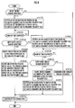
- Fig. 3 is a flow chart illustrating a control processing of ECU 4 according to the operation.
- Fig. 4 is a diagram illustrating flows of phase currents immediately after the processing in STEP 2 illustrated in Fig. 3 is performed.
- Fig. 5 is a graph illustrating wave shapes of the phase currents illustrated in Fig. 4.
- Fig. 6 is a diagram illustrating flows of the phase currents after the processing of the flow chart in Fig. 3 is completed.
- Fig. 7 is a graph illustrating wave shapes of the phase currents illustrated in Fig. 6 .
- the ECU 4 determines whether the occurrence of a short-circuit failure has been detected according to the presence of a short-circuit information input from the control unit 8 of the PDU 3 during the operation of the motor 1 (the driving of the vehicle) (STEP 1). If the short-circuit information is not output from the control unit 8, and the occurrence of a short-circuit failure is not detected (the determination result of STEP 1 is negative), the control processing in Fig.
- the ECU 4 firstly performs a control processing such as switching off the contactor 5 or the like in STEP 2. According thereto, the capacitor 2 is electrically detached from the inverter circuit 7 and the motor 1 (power transfer between the motor 1 and the capacitor 2 is blocked). Moreover, in STEP 2, the ECU 4 also performs a control processing which outputs an instruction to the control unit 8 of the PDU 3 to switch off all the switch elements 11 (six in total) of the inverter circuit 7.
- control unit 8 of the PDU 3 outputs a control signal to the gate of each switch element 11 so as to switch off each switch element 11.
- the switch element 11 in the switch portion 13 (hereinafter, referred to as normal switch portion 13) other than the switch portion 13 where a short-circuit failure has occurred (short-circuit failure switch portion 13) is brought into the OFF state, however, the short-circuit failure switch portion 13 continues to be in the conducted state.
- a phase current of a defined direction (sinusoidal electric current) flows into the armature coil 1u, 1v or 1w (hereinafter, a reference numeral 1x will be attached to the armature coil where appropriate) of one phase corresponding to the short-circuit failure switch portion 13 via the short-circuit failure switch portion 13
- a phase current (sinusoidal electric current) of a different direction from the phase current flowing into the armature coil 1x flows into each of the other armature coils of two phases, respectively, via the feedback diode 12a or 12b at the same polarity side as the short-circuit failure switch portion 13 in the two feedback diodes 12a and 12b in the corresponded arm 10.
- the short-circuit failure switch portion 13 is the switch portion 13a on the positive polarity side of the arm 10u of U phase.
- the phase current flows in a given direction as illustrated by arrows Yu, Yv and Yw in Fig. 4 , respectively.
- the U phase current illustrated by the arrow Yu flows through the switch element 11a or the feedback diode 12a on the positive polarity side of the arm 10u of U phase.
- the V phase current illustrated by the arrow Yv flows through the feedback diode 12a on the positive polarity side of the arm 10v of V phase
- the W phase current illustrated by the arrow Yw flows through the feedback diode 12a on the positive polarity side of the arm 10w of W phase.
- Fig. 5 illustrates an example showing the measured wave shape of each phase current in the mentioned case ( Fig. 4 ).
- the rotation velocity of the output shaft of the motor 1 is 6000 rpm.
- the U phase current is a sinusoidal electric current flowing in the direction of positive polarity.
- the V phase current and the W phase current are both sinusoidal electric currents flowing in the direction of negative polarity (opposite direction of polarity to the U phase current).
- the direction of polarity for each phase current is set as a positive polarity.
- phase current of a phase corresponding to the short-circuit failure switch portion 13a becomes a sinusoidal electric current of positive polarity, and the other two phase currents become sinusoidal electric currents of negative polarity.
- phase current of the phase corresponding to the short-circuit failure switch portion 13a flows through the switch element 11a or the feedback diode 12a of the short-circuit failure switch portion 13a, and the other two phase currents flow respectively through the feedback diode 12a on the positive polarity side of the arm 10 of a corresponding phase.
- the phase current of a phase corresponding to the short-circuit failure switch portion 13b becomes a sinusoidal electric current of negative polarity, and the other two phase currents become sinusoidal electric currents of positive polarity.
- the phase current of the phase corresponding to the short-circuit failure switch portion 13b flows through the switch element 11b or the feedback diode 12b of the short-circuit failure switch portion 13b, and the other two phase currents flow respectively through the feedback diode 12b on the negative polarity side of the arm 10 of a corresponding phase.
- the magnitude (absolute value) of the phase current flowing in the short-circuit failure switch portion 13 is equal to the sum of the magnitudes (absolute value) of the phase currents of the other two phases.
- the rotation velocity of the output shaft of the motor 1 is relatively great, the RMS value of the phase current flowing in the short-circuit failure switch portion 13 becomes relatively large.
- the RMS value of the U phase current is as great as 240A roughly.
- the RMS value of the V phase current and the W phase current is around 145A, smaller than the RMS value of the U phase current.
- the ECU 4 performs a control processing which will be described later after STEP 3 to prevent an excess current from flowing into the short-circuit failure switch portion 13 and the like.
- the ECU 4 performs a recognition processing on the polarity (direction) of each phase current of the motor 1 on the basis of the detection signals from the electric current sensors 9u, 9v and 9w.
- the ECU 4 sequentially samples a value of each phase current detected by each electric current sensor 9 in a given duration and then calculates the average value of each phase current in the duration. Thereafter, the ECU 4 recognizes the polarity (direction) of each phase current on the basis of a sign of the average value. Next in STEP 4, the ECU 4 determines whether or not the polarity of one phase current among the three phase currents is of negative polarity and the other two phase currents are of positive polarity. If the determination result is positive, the ECU 4 confirms that a short-circuit failure has occurred in either of the three switch portions 13b, 13b and 13b on the negative polarity side in STEP 5.
- the ECU 4 outputs to the control unit 8 of the PDU 3 an instruction of switching on all the switch elements 11b, 11b and 11b on the negative polarity side.
- the processing in Fig. 3 is terminated.
- the control unit 8 outputs the control signal of switching on all the switch elements 11b, 11b and 11b on the negative polarity side to the gate of each switch element 11b on the negative polarity side according to the instruction output from the ECU 4.
- the short-circuit failure switch portion 13b and all the switch elements 11b, 11b and 11b on the same polarity side (here, the negative polarity side) as the switch portion 13b are switched on, and consequently, all the switch portions 13b, 13b and 13b on the negative polarity side are brought into the conducted state. Meanwhile, each switch element 11a on the different polarity side (here, the positive polarity side) from the short-circuit failure switch portion 13b is kept in the OFF state.On the other hand, if the determination result in STEP 4 is negative, the ECU 4 determines whether or not the polarity of one phase current among the three phase currents is positive and the other two phase currents is of negative polarity in STEP 7.
- the ECU 4 confirms that a short-circuit failure has occurred in either of the three switch portions 13a, 13a and 13a on the positive polarity side in STEP 8. Thereafter, in STEP 9, the ECU 4 outputs to the control unit 8 of the PDU 3 an instruction of switching on all the switch elements 11a, 11a and 11a on the positive polarity side. The processing in Fig. 3 is terminated.
- the control unit 8 outputs the control signal of switching on all the switch elements 11a, 11a and 11a on the positive polarity side to the gate of each switch element 11a on the positive polarity side according to the instruction output from the ECU 4.
- the short-circuit failure switch portion 13a and all the switch elements 11a, 11a and 11a on the same polarity side (here, the positive polarity side) as the switch portion 13a are switched on, and consequently, all the switch portions 13a, 13a and 13a on the positive polarity side are brought into the conducted state. Meanwhile, each switch element 11b on the different polarity side (here, the negative polarity side) from the short-circuit failure switch portion 13a is kept in the OFF state.
- the two switch elements 11a and 11b of either arm 10 in the inverter circuit 7 may be temporarily brought into the ON state at the same time. Further, after a short-circuit failure occurs in the switch element 11 of either switch portion 13 and the two switch portions 13a and 13b of the arm 10 containing the short-circuit failure switch portion 13 are brought into the conducted state simultaneously, it is possible that a failure may occur to bring the switch element 11 of the switch portion 13 into the OFF state. Even in these cases, the short-circuit information is output from the control unit 8 of the PDU 3 and the control processing starting from STEP 2 is performed according to the present embodiment.
- the short-circuit failure switch portion 13 and all the other switch portions 13 on the same polarity side as the short-circuit failure switch portion 13 are brought into the conducted state, and meanwhile, all the switch elements on the different side from the short-circuit failure switch portion 13 are controlled to be in the OFF state.
- the switch portions 13 at the same polarity side as the short-circuit failure switch portion 13 are in the conducted state in both directions. For example, if a short-circuit failure occurs in the switch portion 13a of U phase on the positive polarity side, as illustrated by the arrows in Fig.
- each phase current is a sinusoidal alternative current having substantially equal amplitude.
- the rotation velocity of the output shaft of the motor 1 in Fig. 7 is the same as that in Fig. 5 .In this situation, the RMS value of each phase current is relative smaller than that in the situation immediately after the contactor 5 is switched off and all the switch elements 11 except the switch element 11 of the switch portion 13 with a short-circuit failure occurred are switched off. For example, as illustrated in Fig.
- the RMS value of each phase current including that of the U phase corresponding to the switch portion 13a on the positive polarity side, namely, the short-circuit failure switch portion, is roughly 81A. Therefore, compared with that in Fig. 5 (240A), the RMS value of the U phase current corresponding to the short-circuit failure switch portion 13a is reduced to one third thereof.Thus, by switching the short-circuit failure switch portion 13 and all the other switch portions 13 on the same polarity side into the conducted state, the excess electric current can be prevented from flowing into the short-circuit failure switch portion 13.
- the motor 1 when the motor 1 is mounted in a hybrid vehicle of a parallel type as an auxiliary driving force generation element, it is possible for the vehicle to have a continual moving driven by an engine thereof used as the other driving force generation element.
- any of the switch portions 13 has a short-circuit failure occurred therein, it is possible that a large electric current would flow into the switch portions 13.
- the conductive plate member such as the beam leads 18a, 18b or the like is disposed in the electric current path of each arm 10 of the inverter circuit 7, an excess current can be prevented from flowing into the switch portion 13 without welding out the conductive member.
- the determination processing is performed in STEP 7; however, it is acceptable to perform the processing in STEP 9 by taking the short-circuit failure switch portion 13 as the switch portion 13 on the positive polarity side when the determination result of STEP 4 is NO.
- Fig. 8 is a flow chart illustrating a control processing of ECU 4 according to the present embodiment.
- the control processing of the ECU 4 which is performed when a short-circuit failure described in the first embodiment occurs, is different from the first embodiment. Therefore, in the descriptions of the present embodiment, the same numerals are used to refer to the same or identical parts or those having identical functions in the first embodiment and descriptions thereof are omitted.
- the ECU 4 in the present embodiment performs the same determination processing in STEP 21 as that of STEP 1 in the first embodiment during the operation of the motor 1 (the driving of the vehicle). If the determination result is negative (the occurrence of a short-circuit failure is not detected by the control unit 8 of the PDU 3), the control processing in Fig. 8 is terminated.
- the ECU 4 outputs an instruction for switching on, for example, all the switch elements 11a, 11a and 11a on the positive polarity side and an instruction for switching off, for example, all the switch elements 11b, 11b and 11b on the negative polarity side to the control unit 8 of the PDU 3. Thereafter, the ECU 4 stands by at this situation for a given standby time (STEP 23). While in standing by, the ECU 4 determines whether or not the occurrence of a new short-circuit failure is detected according to whether a short-circuit information is input from the control unit 8 of the PDU 3 or not in STEP 24.
- the ECU 4 confirms that a short-circuit failure has occurred in either of the three switch portions 13b, 13b and 13b on the negative polarity side in STEP 25. Thereafter in STEP 26, the ECU 4 outputs an instruction to the control unit 8 of the PDU 3 to switch on all the switch elements 11b, 11b and 11b on the negative polarity side and an instruction to the control unit 8 of the PDU 3 to switch off all the switch elements 11a, 11a and 11a on the positive polarity side.
- the control unit 8 of the PDU 3 outputs a control signal for switching on all the switch elements 11b, 11b and 11b on the negative polarity side to the gate of each switch element 11b, and a control signal for switching off all the switch elements 11a, 11a and 11a on the positive polarity side to the gate of each switch element 11a.
- the short-circuit failure switch portion 13b and all the switch elements 11b, 11b and 11b on the same polarity side (the negative polarity side) as the short-circuit failure switch portion 13b are switched on (consequently, all the switch portions 13b, 13b and 13b on the negative polarity side are brought into the conducted state), and all the switch elements 11a, 11a and 11a on the different polarity side (the positive polarity side) from the short-circuit failure switch portion 13b are switched off.
- the ECU 4 switches off the contactor 5 in STEP 33, and the processing in Fig. 8 is terminated.
- the contactor 5 is switched off in order to prevent a minor pulsating electric current from travelling into the capacitor 2, and as a result thereof, to avoid the deterioration or the like of the capacitor 2.
- the ECU 4 When there is no new short-circuit information being output from the control unit 8 during the standby in STEP 23 and the determination result in STEP 24 is negative, the ECU 4 outputs an instruction to the control unit 8 of the PDU 3 to switch on all the switch elements 11b, 11b and 11b on the negative polarity side and an instruction to the control unit 8 of the PDU 3 to switch off all the switch elements 11a, 11a and 11a on the positive polarity side in the subsequent STEP 27. Thereafter, similar to that in STEP 23, the ECU 4 stands by at this situation for a given standby time (STEP 28). While in standing by, the ECU 4 determines whether or not the occurrence of a new short-circuit failure is detected according to whether a short-circuit information is input from the control unit 8 of the PDU 3 or not in STEP 29.
- the ECU 4 confirms that a short-circuit failure has occurred in either of the three switch portions 13a, 13a and 13a on the positive polarity side in STEP 30. Thereafter in STEP 31, the ECU 4 outputs an instruction to the control unit 8 of the PDU 3 to switch on all the switch elements 11a, 11a and 11a on the positive polarity side and an instruction to the control unit 8 of the PDU 3 to switch off all the switch elements 11b, 11b and 11b on the negative polarity side.
- control unit 8 of the PDU 3 outputs a control signal to the gate of each switch element 11a to switch on all the switch elements 11a, 11a and 11a on the positive polarity side, and a control signal to the gate of each switch element 11b to switch off all the switch elements 11b, 11b and 11b on the negative polarity side.
- the short-circuit failure switch portion 13a and all the switch elements 11a, 11a and 11a on the same polarity side (the positive polarity side) as the short-circuit failure switch portion 13a are switched on (consequently, all the switch portions 13a, 13a and 13a on the positive polarity side are brought into the conducted state), and all the switch elements 11b, 11b and 11b on the different polarity side (the negative polarity side) from the short-circuit failure switch portion 13a are switched off.
- the ECU 4 confirms that a common short-circuit is occurred in STEP 32. Thereafter, the ECU 4 terminates the processing of Fig. 8 after the processing in STEP 33 (switching off the contactor 5).
- the situation where the determination result in STEP 29 is negative means that either switch portion 13 has no the short-circuit failure occurred therein. Specifically, similar to the situation where the determination result is negative in STEP 7 of Fig.
- the situation where the determination result in STEP 29 is negative means that the two switch elements 11a and 11b of either arm 10 in the inverter circuit 7 are temporarily brought into the ON state by the noises during the operation of the motor 1, and consequently, the determination result of STEP 21 is positive; or after either switch portion 13 temporarily has encountered a short-circuit failure, the switch elements 11 of the switch portion 13 encounter a failure of being in a continual OFF state.
- "A common short-circuit" in STEP 29 means that the switch portion 13 is temporarily in a short-circuit failure state.
- the processing in STEP 22 to STEP 25, STEP 28 to STEP 30 in the present embodiment is fulfilled by the short-circuit failure polarity determining member of the present invention.
- the processing in STEP 27 and STEP 32 is fulfilled by the short-circuit failure controlling member of the present invention.
- the motor 1 when the motor 1 is mounted in a hybrid vehicle of a parallel type as an auxiliary driving force generation element, it is possible for the vehicle to have a continual moving driven by an engine used as the other driving force generation element thereof.
- the electric current path of each arm 10 in the inverter circuit 7 is disposed with the beam leads 18a and 18b, therefore, similar to the first embodiment, the electric current flowing through the switch portions 13 can be effectively prevented from becoming excessively great.
- the processing from STEP 27 to STEP 29 is performed when the determination result in STEP 24 is NO, it is acceptable to determine that the short-circuit failure switch portion 13 is the switch portion 13a on the positive polarity side when the determination result in STEP 24 is NO and perform the processing in STEP 31 thereafter. It is acceptable to perform the processing from STEP 27 to STEP 29 as a substitute for the processing from STEP 22 to STEP 24, and perform the processing in STEP 31 and STEP 26, respectively, in accordance with the positive or negative determination result in STEP 29. It is also acceptable to reverse the processing order of the determination processing from STEP 22 to STEP 24 and the processing from STEP 27 to STEP 29 mentioned in the present embodiment. Furthermore, it is acceptable to omit the processing of switching off the contactor 5 in STEP 33.
- the current sensitive IGBT is used as the switch element 11 of the inverter circuit 7, and the occurrence of a short-circuit failure is detected by the control unit 8 according to the current detection signal output from the IGBT.
- the control unit 8 it is acceptable to detect the occurrence of a short-circuit failure with the other approaches.
- the present invention is applicable as a control unit of a motor or a vehicle mounted with the motor capable of preventing a great electric current from flowing into each switch portion of an inverter circuit when a short-circuit failure occurs in either switch portion of the inverter circuit.
Landscapes
- Engineering & Computer Science (AREA)
- Power Engineering (AREA)
- Life Sciences & Earth Sciences (AREA)
- Sustainable Development (AREA)
- Sustainable Energy (AREA)
- Transportation (AREA)
- Mechanical Engineering (AREA)
- Inverter Devices (AREA)
- Control Of Ac Motors In General (AREA)
- Electric Propulsion And Braking For Vehicles (AREA)
- Control Of Motors That Do Not Use Commutators (AREA)
- Protection Of Static Devices (AREA)
Abstract
Description
- The present invention relates to a controller for a motor used as a driving force generation element or the like for a vehicle, and a vehicle mounted with the motor.
- Generally, a motor having an armature of multiple phases, such as a brushless direct-current motor of three phases, is mounted in a vehicle such as a hybrid vehicle or an electric vehicle and is used as a driving force generation element for the vehicle. The operation control of the motor is generally performed by supplying electric power from a capacitor such as a battery or the like through the intermediary of an inverter (PWM inverter) circuit of multiple phases to the motor (for example, refer to Japanese Patent Laid-open No.
H9-46811 - In general, the inverter circuit designated by a
reference number 7 has a circuit configuration illustrated inFig. 1 , for example. As illustrated, theinverter circuit 7 is constituted by connecting inparallel arms arms switch portion 13a disposed on a positive polarity side and aswitch portion 13b disposed on a negative polarity side. Theswitch portion 13a is constituted by connecting aswitch element 11a and afeedback diode 12a in parallel. Theswitch portion 13b is constituted by connecting aswitch element 11b and afeedback diode 12b in parallel. - When the motor is in operation, a short-circuit failure may occur in either switch portion of the inverter circuit so that the switch portion is kept in a continual conducted state despite a control signal output to a switch element of the switch portion. The conducted state of a switch portion described in the present invention means that both terminals of the switch portion are substantially short-circuited and an electric current can flow in the switch portion in both directions. When a switch element and a feedback diode of a switch portion are functioning normally, the conducted state of the switch portion is equivalent to the conducted state (ON state) of the switch element. Moreover, a short-circuit failure state of the switch portion means that the switch element of the switch portion is switched on (conducted state) continuously despite a control signal output to the switch element, or a feedback diode is in the conducted state in both directions, namely, a forward direction and a backward direction thereof.
- When a short-circuit failure occurs, if the ON/OFF (conduction/disconnection) control of switch elements in a normal switch portion other than the switch portion occurred with the short-circuit failure is continued, there arises a problem that an excess electric current would flow in the switch portion or the like where the short-circuit has occurred according to an electromotive force occurred in each phase of the motor.
- In this regard, the art disclosed in Japanese Patent Laid-open No.
H9-46811 - However, according to the art disclosed in
Patent Document 1, multiple switches would be necessary, and therefore, it is disadvantageous. - The present invention has been accomplished in view of the aforementioned problems, and it is therefore an object of the present invention to provide a controller for a motor capable of preventing a large electric current from flowing into each switch portion of an inverter circuit without the need of providing a switch or the like to block the power distribution between the motor and the inverter circuit when a short-circuit failure occurs in any of the switch portions of the inverter circuit during the operation of the motor by means of an appropriate ON/OFF control (conduction/ blockade control) on switch elements in the normal switch portions of the inverter circuit, and a vehicle.
- To attain an object described above, the controller for the motor of the present invention, which is powered by a direct-current power source via a multi-phase inverter circuit composed of switch portions having switch elements and feedback diodes connected in parallel to the switch elements disposed at a positive polarity side and a negative polarity side of an arm of each phase, includes: a short-circuit failure detecting member configured to detect an occurrence of a short-circuit failure which causes any switch portion in the inverter circuit to be in a continual conducted state during the operation of the motor; a short-circuit failure polarity determining member configured to determine whether a short-circuit failure switch portion in which an occurrence of a short-circuit failure has been detected by the short-circuit failure detecting member is on the positive polarity side or on the negative polarity side; and a short-circuit failure controlling member configured to control each of the other switch elements except at least the switch element of the short-circuit failure switch portion among the switch portions in the inverter circuit in such a way that all the switch portions on the same polarity side as the short-circuit failure switch portion determined by the short-circuit failure polarity determining member are set in a conducted state and all the switch elements of all the switch portions on the different polarity side from the short-circuit failure switch portion are set in a disconnected state.
- The vehicle of the present invention, which is provided with a motor as a driving force generating element, the motor being powered by a direct-current power source via a multi-phase inverter circuit composed of switch portions having switch elements and feedback diodes connected in parallel to the switch elements disposed at a positive polarity side and a negative polarity side of an arm of each phase, includes: a short-circuit failure detecting member configured to detect an occurrence of a short-circuit failure which causes any switch portion in the inverter circuit to be in a continual conducted state during the operation of the motor; a short-circuit failure polarity determining member configured to determine whether a short-circuit failure switch portion in which an occurrence of a short-circuit failure has been detected by the short-circuit failure detecting member is on the positive polarity side or on the negative polarity side; and a short-circuit failure controlling member configured to control each of the other switch elements except at least the switch element of the short-circuit failure switch portion among the switch portions in the inverter circuit in such a way that all the switch portions on the same polarity side as the short-circuit failure switch portion determined by the short-circuit failure polarity determining member are set in a conducted state and all the switch elements of all the switch portions on the different polarity side from the short-circuit failure switch portion are set in a disconnected state.
- According to the controller for the motor and the vehicle of the present invention, when an occurrence of a short-circuit failure at any switch portion of the inverter circuit is detected by the short-circuit failure detecting member, whether the short-circuit failure switch portion where the short-circuit failure has occurred is on the positive polarity side (the so-called high side) or on the negative polarity side (the so-called low side)of the inverter circuit is determined by the short-circuit failure polarity determining member. Subsequently, each of the other switch elements except at least the switch element of the short-circuit failure switch portion among the switch portions in the inverter circuit is controlled by the short-circuit failure controlling member in such a way that all the switch portions on the same polarity side as the short-circuit failure switch portion determined by the short-circuit failure polarity determining member are set in a conducted state and all the switch elements of all the switch portions on the different polarity side from the short-circuit failure switch portion are set in a disconnected state.
- More specifically, when a short-circuit failure switch portion is determined to be on the positive polarity side, all the switch elements except at least the switch element of the short-circuit failure switch portion on the positive polarity side are controlled to be in the conducted state (ON state) and all the switch elements on the negative polarity side are controlled to be in the disconnected state (OFF state). Meanwhile, when a short-circuit failure switch portion is determined to be on the negative polarity side, all the switch elements except at least the switch element of the short-circuit failure switch portion on the negative polarity side are controlled to be in the conducted state (ON state) and all the switch elements on the positive polarity side are controlled to be in the disconnected state (OFF state)
- The short-circuit failure state of a short-circuit switch portion may be caused by a failure on a switch element of the short-circuit failure switch portion and a failure on a feedback diode. In either case, the short-circuit failure switch is kept in the conducted state despite the control on the switch element of the short-circuit failure switch portion. Therefore, it is not obligatory for the short-circuit failure controlling member to control the switch element of the short-circuit failure switch portion so that the switch element is in the conducted state, however, it is acceptable.
- At this time, since all the switch portions, including the short-circuit failure switch portion, at the same polarity side as the short-circuit failure switch portion are in the conducted state, the armature coils of each phase in the motor are brought into a mutual short-circuit state through the switch portions being in the conducted state. In this case, the conducted switch portions of each phase of the inverter circuit is flown with a phase current of a magnitude level substantially equal for each phase generated according to the rotation of an output shaft of the motor, the phase current will not be particularly large. Therefore, according to the controller for the motor and the vehicle of the present invention, it is possible to prevent a large electric current from flowing into each switch portion of the inverter circuit without the need of providing a switch or the like to block the power distribution between the motor and the inverter circuit when a short-circuit failure occurs in any of the switch portions of the inverter circuit during the operation of the motor by means of an appropriate ON/OFF control (conduction/ blockade control) on switch elements in the normal switch portions of the inverter circuit. In particular, when the motor is mounted in a hybrid vehicle of a parallel type as a driving force generation element, it is possible to enable a continued driving for the vehicle driven by an engine.
- In the controller for the motor and the vehicle according to the present invention, the short-circuit failure polarity determining member can determine whether the short-circuit failure switch element is on the positive polarity side or on the negative polarity side according to what is mentioned below.
- For example, the controller further includes a phase current detecting member configured to detect a phase current of each phase of the motor, wherein the short-circuit failure polarity determining member determines whether the short-circuit failure switch portion is on the positive polarity side or on the negative polarity side according to a direction of each phase current detected by the phase current detecting member after short-circuit failure polarity determining member has set a power source switch disposed in a power distribution path between the direct-current power source and the inverter circuit in the disconnected state and has output a control signal to all the switch elements in the inverter circuit to set the switch element in the disconnected state.
- In other words, in the state where a control signal is output to all the switch elements of the inverter circuit to switch off the switch elements, the short-circuit failure switch portion of the inverter circuit is brought into the conducted state despite the control signal output to the switch elements thereof and the switch elements of the other normal switch portions are in the disconnected state. In this case, each phase current is of the same direction. Moreover, each phase current in the case where the short-circuit failure switch portion is on the positive polarity side and each phase current in the case where the short-circuit failure switch portion is on the negative polarity side are of opposite directions. Accordingly, whether the short-circuit failure switch portion is on the positive polarity side or on the negative polarity side can be determined according to the direction of each phase current detected by the phase current detecting member.
- In the case where the short-circuit failure detecting member detects a short-circuit has occurred on a condition whether a switch portion on the positive polarity side and a switch portion on the negative polarity side of an arm corresponding to any of the phase of the inverter circuit during the operation of the motor, the short-circuit failure determining member can detect whether the short-circuit failure switch portion is on the positive polarity side or on the negative polarity side according to whether or not the occurrence of a short-circuit failure has been detected by the short-circuit failure detecting member after short-circuit failure polarity determining member maintains a power source switch disposed in a power distribution path between the direct-current power source and the inverter circuit in the conducted state, outputs a control signal to all the switch elements on any of the positive polarity side and the negative polarity side of the inverter circuit to set the switch elements in the conducted state and a control signal to all the switch elements on the other polarity side to set the switch elements in the disconnected state.
- In other words, by maintaining the power source switch disposed in the power distribution path between the direct-current power source and the inverter circuit in the conducted state, outputting a control signal to all the switch elements on any of the positive polarity side and the negative polarity side, which is the different polarity side from the short-circuit failure switch portion, of the inverter circuit to set the switch elements in the conducted state (ON state) and a control signal to all the switch elements on the other polarity side, which is the same polarity side as the short-circuit failure switch portion, to set the switch elements in the disconnected state (OFF state), the switch portions on the positive polarity side and the switch portions on the negative polarity side of a phase corresponding to the short-circuit failure switch portion of the inverter circuit are brought into the conducted state simultaneously. Accordingly, an excess short-circuit current flows through the short-circuit failure switch portion and the switch portions connected thereto in series from the direct-current power source or a smoothing condenser generally disposed on the input side of the inverter circuit. Thus, the occurrence of a short-circuit failure can be detected by the short-circuit failure detecting member.
- On the other hand, when a control signal is output to all the switch elements on the same polarity side as the short-circuit failure switch portion to set the switch elements in the conducted state (ON state) and a control signal is output to all the switch elements on the different polarity side from the short-circuit failure switch portion to set the switch elements in the disconnected state (OFF state), the switch portions on the positive polarity side and the switch portions on the negative polarity side in either phase of the inverter circuit cannot be brought into the conducted state simultaneously. Therefore, in this case, there will be no short-circuit failure to be detected by the short-circuit failure detecting member.
- Therefore, by maintaining the power source switch disposed in the power distribution path between the direct-current power source and the inverter circuit in the conducted state, and outputting a control signal to all the switch elements on any of the positive polarity side and the negative polarity side of the inverter circuit to set the switch elements in the conducted state and a control signal to all the switch elements on the other polarity side to set the switch elements in the disconnected state, whether the short-circuit failure switch element is on the positive polarity side or on the negative polarity side can be determined according to whether or not the occurrence of the short-circuit failure has been detected by the short-circuit failure detecting member.
- According to the vehicle of the present invention, it is desirable that a parallel connection of the switch element and the feedback diode in each switch portion, a series connection of the switch portion on the positive polarity side and the switch portion on the negative polarity side, a connection of a pair of power source terminals and a series circuit of the switch portion on the positive polarity side and the switch portion on the negative polarity side, and a connection of an output terminal and a central point of the series circuit of the switch portion on the positive polarity side and the switch portion on the negative polarity side of each arm in the inverter circuit are conducted through a conductive plate member.
- In other words, in the vehicle provided with the motor used as the driving force generation element of the vehicle, even though a power distribution control is not performed on the motor, the output shaft of the motor will be driven to rotate by the kinetic energy or the engine of the vehicle. Consequently, an electromotive force occurs in the armatures of each phase of the motor. Therefore, by providing the conductive plate member in each arm of the inverter circuit, when a short-circuit failure occurs in either switch portion, the conductive member can endure a large electric current to flow therethrough without being fused. Accordingly, in the vehicle of the present invention, the excess current can be prevented from flowing into the switch portion of the inverter circuit or the conductive member of the arm by controlling the switching elements of the inverter circuit as mentioned above.
-
-
Fig. 1 is a diagram illustrating a circuit of a controller of a motor according to an embodiment of the present invention. -
Fig. 2 is a perspective structural view of an arm of an inverter circuit provided in the controller illustrated inFig. 1 . -
Fig. 3 is a flow chart illustrating a control processing of ECU according to a first embodiment. -
Fig. 4 is a diagram illustrating flows of phase currents immediately after the processing inSTEP 2 illustrated inFig. 3 is performed. -
Fig. 5 is a graph illustrating wave shapes of the phase currents illustrated inFig. 4 . -
Fig. 6 is a diagram illustrating flows of the phase currents after the processing of the flow chart inFig. 3 is completed. -
Fig. 7 is a graph illustrating wave shapes of the phase currents illustrated inFig. 6 . -
Fig. 8 is a flow chart illustrating a control processing of ECU according to a second embodiment. - A first embodiment of the present invention will be described in detail with reference to
Fig. 1 to Fig. 7 . - Illustrated in
Fig. 1 is a circuit configuration of a controller of a motor in the first embodiment. InFig. 1 , thereference numeral 1 denotes a motor, thereference numeral 2 denotes a capacitor used as a direct-current power source for themotor 1, thereference numeral 3 denotes a power drive circuit unit (hereinafter, referred to as PDU) of themotor 1, and thereference numeral 4 denotes an electronic control unit (hereinafter, referred to as ECU) for performing an operation control on themotor 1 through the intermediary of the powerdrive circuit unit 3. - The
motor 1 is a 3-phase brushless DC motor, for example. In the present embodiment, themotor 1 is mounted in a hybrid vehicle of a parallel type (not shown) as an auxiliary driving force generation element. It is also acceptable to mount themotor 1 in an electric vehicle or in a hybrid vehicle of a series type (not shown) as a driving force generation element. In the case of the hybrid vehicle of a parallel type, an output shaft (rotor) of themotor 1 is connected with an output shaft of an engine and a drive wheel of the vehicle through the intermediary of a transmission, a crutch or the like. In the case of the electric vehicle or the hybrid vehicle of a series type, the output shaft of themotor 1 is connected with a drive wheel of the vehicle through the intermediary of a transmission, a crutch or the like. The structure of the mentioned vehicle may be publicly known. - The
capacitor 2 is a secondary battery which can be charged and discharged. A positive pole of thecapacitor 2 is connected with a power source terminal 3a on the positive polarity side of thePDU 3 through the intermediary of acontactor 5, and a negative pole thereof is connected with a power source terminal 3b on the negative polarity side of thePDU 3. Thecontactor 5 functions as a power source switch for themotor 1. By switching on the contactor 5 (conducted state), thecapacitor 2 is enabled to supply power to an inverter circuit 7 (to be described hereinafter) of thePDU 3. It is acceptable to use a high-capacity condenser such as a two-layered electric condenser or the like as thecapacitor 2. It is also acceptable to use a direct-current power source capable of applying a direct-current voltage from thecapacitor 2 to thePDU 3 through a bi-directional DC-DC convertor. - The
PDU 3 is provided with a smoothingcondenser 6, theinverter circuit 7, acontrol unit 8 which controls the operation of theinverter circuit 7 according to an instruction issued from theECU 4, and electriccurrent sensors 9u, 9v, 9w which are used as electric current detecting members for detecting electric currents (phase currents) in armature coils 1u, 1v, 1w of each phase (U phase, V phase, and W phase) of themotor 1, respectively. The smoothingcondenser 6 is connected between thepower source terminals 3a and 3b. However, if two phase currents among the three are defined, the last phase current can be defined unambiguously, thus, either one of the electriccurrent sensors 9u, 9v and 9w can be omitted. - The
inverter circuit 7 is a 3-phase inverter circuit constituted by connectingarms motor 1, respectively, with the smoothingcondenser 6 in parallel between thepower source terminals 3a and 3b. Each of thearms inverter circuit 7 is composed of a pair ofswitch elements feedback diodes switch elements arms switch portion 13a and aswitch portion 13b. Theswitch portion 13a is constituted by connecting in parallel theswitch element 11a and thefeedback diode 12a, and theswitch portion 13b is constituted by connecting in parallel theswitch element 11b and thefeedback diode 12b. - In the present embodiment, each of the
switch elements arms switch portions motor 1 through the intermediary of the electriccurrent sensors 9u, 9v and 9w, respectively.Specifically, the IGBT included in each of theswitch elements arms switch element 11a (cathode of the collector of theswitch element 11a and cathode of thefeedback diode 12a) is connected with the power source terminal 3a of thepower source terminals 3a and 3b at the positive polarity side, and the other end closer to theswitch element 11b (cathode of the emitter of theswitch element 11b and anode of thefeedback diode 12b) is connected with thepower source terminal 3b at the negative polarity side. Hereinafter, theswitch element 11a and theswitch element 11b may be referred to as the positive polarityside switch element 11a and the negative polarityside switch element 11b, respectively, where appropriate. Similarly, thefeedback diode 12a and thefeedback diode 12b may be referred to as the positive polarityside feedback diode 12a and thefeedback diode 12b, respectively, where appropriate; theswitch element 13a and theswitch element 13b may be referred to as the positive polarityside switch element 13a and the negative polarityside switch element 13b, respectively, where appropriate. Further, when there is no necessity to differentiate in particular the phases of thearms current sensors 9u, 9v and 9w of theinverter circuit 7, the suffix letters u, v and w are omitted. Furthermore, when there is no necessity to differentiate in particular theswitch elements arm 10, thefeedback diodes switch portions arm 10 of theinverter circuit 7 according to the present embodiment will be described with reference toFig. 2. Fig. 2 is a diagram illustrating an outline of the structure thereof in profile.As illustrated, eacharm 10 is provided with aheat sink 14, aninsulation sheet 15 andheat spreaders 16a and 16b. Theheat spreaders 16a and 16b are mounted on theheat sink 14 without inter contact thereto with theinsulation sheet 15 intervened therebetween. Each of theheat spreaders 16a and 16b is used as a conductive plate member in the present embodiment. The materials for theheat spreaders 16a and 16b may be copper, for example. A chip of the switch element (IGBT) 11a and a chip of thefeedback diode 12a are fixed on an upper surface of the heat spreader 16a through asolder 17a. Similarly, a chip of the switch element (IGBT) 11b and a chip of thefeedback diode 12b are fixed on the upper surface of theheat spreader 16b through asolder 17b. Thus, the emitter of theswitch element 11a and the anode of thefeedback 12a are connected through the heat spreader 16a and are conducted to the heat spreader 16a. Similarly, the emitter of theswitch element 11b and the anode of thefeedback 12b are connected through theheat spreader 16b. - Upper surfaces of the chips of the
switch 11a and thefeedback diode 12a are fixed with abeam lead 18a serving as the conductive plate member through asolder 19a, and upper surfaces of the chips of theswitch 11b and thefeedback diode 12b are fixed with abeam lead 18b serving as the conductive plate member through asolder 19b. The materials of the beam leads 18a and 18b may be copper, for example. Thus, the collector of theswitch element 11a and the cathode of thefeedback 12a are connected through thebeam lead 18a and are conducted to thebeam lead 18a. Similarly, the collector of theswitch element 11b and the cathode of thefeedback 12b are connected through thebeam lead 18b. A plate-like connection portion 20 is integrally extended from thebeam lead 18b toward the heat spreader 16a, and is conductively fixed to the heat spreader 16a by a screw or the like.Eacharm 10 is provided withpower source terminals 21a and 21b, and anoutput terminal 22. Thepower source terminals 21a and 21b are connected to the power source terminals 3a at the positive polarity side and thepower source terminals 3b at the negative polarity side of thePDU 3, respectively. Theoutput terminal 22 is connected to either of the armature coils 1u, 1v and 1w of one phase (corresponding to each of thearms motor 1. Thepower source terminal 21a is integrally formed at one end portion of thebeam lead 18a. The power source terminal 21b is integrally formed at one end portion of aconductive plate member 23 which is conductively fixed at theheat spreader 16b through a screw or the like. Theoutput terminal 22 is integrally formed at a portion extended from one side (the portion extended vertical to the paper inFig. 2 ) of thebeam lead 18b. The materials for theconductive member 23 may be copper, for example.According to the above-mentioned connections and structures, theswitch element 11a and thefeedback diode 12a are connected in parallel through the heat spreader 16a serving as the conductive plate member and thebeam lead 18a, and resultantly, to form theswitch portion 13a. Similarly, theswitch element 11b and thefeedback diode 12b are connected in parallel through theheat spreader 16b serving as the conductive plate member and thebeam lead 18b, and resultantly, to form theswitch portion 13b. Theswitch portions connection portion 20 of the beam lead 18. The connection between thepower source terminal 17a and one end of the series circuit of theswitch portions switch portion 13a is fulfilled by thebeam lead 18a serving as the conductive plate member. The connection between the power source terminal 21b and the other end of the series circuit of theswitch portions switch portion 13b is fulfilled by theconductive plate member 23. Moreover, the connection between theoutput terminal 22 and the central point of the series circuit of theswitch portions beam lead 18b serving as the conductive plate member.Accordingly, theinverter circuit 7 of the present embodiment, the electric current path of eacharm 10 is formed through theheat spreaders 16a and 16b serving as the conductive plate member, the beam leads 18a and 18b, theconductive member 23. According thereto, it is difficult for them to be fused out even a large electric current flows into these members.Back again with reference toFig. 1 , thecontrol unit 8 of thePDU 3, a detailed illustration thereof is omitted, is a circuit including a micro computer and a control signal generating circuit configured to output a control signal to each switch element 11. An instruction from the ECU 4 (instruction for designating an operation state for the motor 1) and a detection signal of an electric current in each switch element 11 are input to thecontrol unit 8. Thecontrol unit 8 has a function of generating and outputting a control signal to the gate of each switch element 11 in accordance with the instruction fromECU 4 according to PWM control (hereinafter, referred to as a PWM control function), and a function of forcibly switching off the switch element 11 (cancel the output of a control signal for switching on the switch element 11) flown with an electric current when the electric current determined according to a detection signal input from each switch element 11 is an excess current equal to or greater than a given value (for example, equal to or greater than 400A) and outputting an information signal thereof to theECU 4 as a short-circuit information (hereinafter, referred to as a short-circuit detection function).During the operation of the motor 1 (a state where electric power is being supplied from thecapacitor 2 to the motor 1), twoswitch elements arm 10 in theinverter circuit 7 are controlled according to the PWM control so that both will not be brought into an ON state simultaneously (twoswitch portions arm 10 will not be brought into a conducted state simultaneously). However, for example, when a failure which keeps either switch element 11 in a continual ON state despite a control signal output thereto or a failure which causes either diode 12 to be short-circuited continuously in the forward and backward directions, in other words, a short-circuit failure which keeps either switch portion 13 in a continual conducted state occurs, two switch portions of thearm 10 including the switch portion 13 with the short-circuit failure occurred therein are brought into the conducted state simultaneously. At this situation, a large electric current (short-circuit current) flows into twoswitch portions capacitor 2 or the smoothingcondenser 6. The above-mentioned short-circuit detection function of thecontrol unit 8 functions in this situation. In the present embodiment, thecontrol unit 8 of thePDU 3 having the short-circuit detection function is used as a short-circuit failure detecting member in the present invention.TheECU 4 is a circuit unit provided with a CPU, a RAM and a ROM. The detection signal from each electric current sensor 9 and the short-circuit information from thecontrol unit 8 of thePDU 3 are input to theECU 4. Thereafter, theECU 4 sequentially generates an instruction (for example, a voltage instruction value for each phase of the motor 1) specifying an ON/OFF timing for each switch element 11 of theinverter circuit 7 according to a feedback control processing so that the electric current value determined according to the detection signal from each electric current sensor 9 (detection value of the phase current) approximates to a desired value during the operation of themotor 1, and outputs the generated instruction to thecontrol unit 8 of thePDU 3. The desired value of each phase current of themotor 1 may be determined in accordance with a torque instruction value (instruction value on an output torque from the motor 1). The torque instruction value may be determined according to an operation amount of an accelerator of the vehicle.TheECU 4 functions as a short-circuit failure polarity determining member and a short-circuit failure controlling member in the present invention, and performs a control processing for determining whether the switch portion 13 with a short-circuit failure occurred therein (hereinafter, referred to as the short-circuit failure switch portion 13) is a positive polarity side switch portion or a negative polarity side switch portion according to the short-circuit information input from thecontrol unit 8 of thePDU 3, and a control processing for switching on all the switch elements 11 on the same polarity side as the short-circuit failure switch portion 13 and switching off all the switch element 11 on the different polarity side from the short-circuit failure switch portion 13. Detailed description on these control processes will be carried out hereinafter.The operation of the controller of the present embodiment, particularly when a short-circuit failure occurs in either switch portion 13 of theinverter circuit 7 will be described with reference to thedrawings 3 to 7.Fig. 3 is a flow chart illustrating a control processing ofECU 4 according to the operation.Fig. 4 is a diagram illustrating flows of phase currents immediately after the processing inSTEP 2 illustrated inFig. 3 is performed.Fig. 5 is a graph illustrating wave shapes of the phase currents illustrated inFig. 4. Fig. 6 is a diagram illustrating flows of the phase currents after the processing of the flow chart inFig. 3 is completed.Fig. 7 is a graph illustrating wave shapes of the phase currents illustrated inFig. 6 . - With reference to
Fig. 3 , theECU 4 determines whether the occurrence of a short-circuit failure has been detected according to the presence of a short-circuit information input from thecontrol unit 8 of thePDU 3 during the operation of the motor 1 (the driving of the vehicle) (STEP 1). If the short-circuit information is not output from thecontrol unit 8, and the occurrence of a short-circuit failure is not detected (the determination result ofSTEP 1 is negative), the control processing inFig. 3 is terminated.On the other hand, if the short-circuit information is output from thecontrol unit 8, and therefore the occurrence of the short-circuit failure has been detected (the determination result ofSTEP 1 is positive), theECU 4 firstly performs a control processing such as switching off thecontactor 5 or the like inSTEP 2. According thereto, thecapacitor 2 is electrically detached from theinverter circuit 7 and the motor 1 (power transfer between themotor 1 and thecapacitor 2 is blocked). Moreover, inSTEP 2, theECU 4 also performs a control processing which outputs an instruction to thecontrol unit 8 of thePDU 3 to switch off all the switch elements 11 (six in total) of theinverter circuit 7. According thereto, thecontrol unit 8 of thePDU 3 outputs a control signal to the gate of each switch element 11 so as to switch off each switch element 11.According to the processing inSTEP 2, the switch element 11 in the switch portion 13 (hereinafter, referred to as normal switch portion 13) other than the switch portion 13 where a short-circuit failure has occurred (short-circuit failure switch portion 13) is brought into the OFF state, however, the short-circuit failure switch portion 13 continues to be in the conducted state. In other words, when the switch element 11 of the short-circuit failure switch portion 13 is malfunctioned to be in a continual ON state, even a control signal for switching off the switch element 11 is output thereto, the switch element 11 is kept in the ON state and the conducted state of the short-circuit failure switch portion 13 is continued. Moreover, when the switch element 11 of the short-circuit failure switch portion 13 is functional and the feedback diode 12 is malfunctioned to be conductive in both directions, the switch element 11 of the short-circuit failure switch portion 13 is brought into the OFF state, however, the conducted state of the short-circuit failure switch portion 13 is continued. In addition, when the output shaft of themotor 1 is driven to rotate by the inertia force due to the driving of the vehicle or by the engine disposed in a hybrid vehicle of a parallel type, an electromotive force is generated in accordance with the rotation velocity of the output shaft in the armature coils 1u, 1v and 1w of each phase of themotor 1. - In this situation, at the same time when a phase current of a defined direction (sinusoidal electric current) flows into the armature coil 1u, 1v or 1w (hereinafter, a reference numeral 1x will be attached to the armature coil where appropriate) of one phase corresponding to the short-circuit failure switch portion 13 via the short-circuit failure switch portion 13, a phase current (sinusoidal electric current) of a different direction from the phase current flowing into the armature coil 1x flows into each of the other armature coils of two phases, respectively, via the
feedback diode feedback diodes switch portion 13a on the positive polarity side of thearm 10u of U phase. In the case where thecontactor 5 is switched off and the switch elements 11 of the normal switch portion 13 (theswitch element 11b of thearm 10u, theswitch elements arm 10v and theswitch elements arm 10w) are switched off, the phase current flows in a given direction as illustrated by arrows Yu, Yv and Yw inFig. 4 , respectively. As illustrated, the U phase current illustrated by the arrow Yu flows through theswitch element 11a or thefeedback diode 12a on the positive polarity side of thearm 10u of U phase. The V phase current illustrated by the arrow Yv flows through thefeedback diode 12a on the positive polarity side of thearm 10v of V phase, and the W phase current illustrated by the arrow Yw flows through thefeedback diode 12a on the positive polarity side of thearm 10w of W phase.Fig. 5 illustrates an example showing the measured wave shape of each phase current in the mentioned case (Fig. 4 ). In the example, the rotation velocity of the output shaft of themotor 1 is 6000 rpm. As illustrated, the U phase current is a sinusoidal electric current flowing in the direction of positive polarity. The V phase current and the W phase current are both sinusoidal electric currents flowing in the direction of negative polarity (opposite direction of polarity to the U phase current). In the present embodiment, if a phase current is flowing from theinverter circuit 7 toward each of the phase armatures 1u, 1v and 1w, the direction of polarity for each phase current is set as a positive polarity. - As mentioned above, when one
switch portion 13a among the switch portions 13 of theinverter circuit 7 on the positive polarity side becomes a short-circuit failure switch portion, the phase current of a phase corresponding to the short-circuitfailure switch portion 13a becomes a sinusoidal electric current of positive polarity, and the other two phase currents become sinusoidal electric currents of negative polarity. Herein, the phase current of the phase corresponding to the short-circuitfailure switch portion 13a flows through theswitch element 11a or thefeedback diode 12a of the short-circuitfailure switch portion 13a, and the other two phase currents flow respectively through thefeedback diode 12a on the positive polarity side of thearm 10 of a corresponding phase.Similarly, when oneswitch portion 13b among the switch portions 13 on the negative polarity side becomes a short-circuit failure switch portion, the phase current of a phase corresponding to the short-circuitfailure switch portion 13b becomes a sinusoidal electric current of negative polarity, and the other two phase currents become sinusoidal electric currents of positive polarity. Herein, the phase current of the phase corresponding to the short-circuitfailure switch portion 13b flows through theswitch element 11b or thefeedback diode 12b of the short-circuitfailure switch portion 13b, and the other two phase currents flow respectively through thefeedback diode 12b on the negative polarity side of thearm 10 of a corresponding phase. In the above-mentioned cases, the magnitude (absolute value) of the phase current flowing in the short-circuit failure switch portion 13 is equal to the sum of the magnitudes (absolute value) of the phase currents of the other two phases. However, when the rotation velocity of the output shaft of themotor 1 is relatively great, the RMS value of the phase current flowing in the short-circuit failure switch portion 13 becomes relatively large. For example, in the example ofFig. 5 , the RMS value of the U phase current is as great as 240A roughly. Meanwhile, the RMS value of the V phase current and the W phase current is around 145A, smaller than the RMS value of the U phase current. Thus, if a great phase current continues to flow through the short-circuit failure switch portion 13, the chip in the switch element 11 and the feedback diode 12, and the electrical wires in thebeam lead 16a or 16b are probably subjected to an excessively high temperature.Therefore, in the present embodiment, subsequent toSTEP 2, theECU 4 performs a control processing which will be described later afterSTEP 3 to prevent an excess current from flowing into the short-circuit failure switch portion 13 and thelike.In STEP 3, theECU 4 performs a recognition processing on the polarity (direction) of each phase current of themotor 1 on the basis of the detection signals from the electriccurrent sensors 9u, 9v and 9w. Specifically, theECU 4, for example, sequentially samples a value of each phase current detected by each electric current sensor 9 in a given duration and then calculates the average value of each phase current in the duration. Thereafter, theECU 4 recognizes the polarity (direction) of each phase current on the basis of a sign of the average value.Next inSTEP 4, theECU 4 determines whether or not the polarity of one phase current among the three phase currents is of negative polarity and the other two phase currents are of positive polarity. If the determination result is positive, theECU 4 confirms that a short-circuit failure has occurred in either of the threeswitch portions STEP 5. Thereafter, inSTEP 6, theECU 4 outputs to thecontrol unit 8 of thePDU 3 an instruction of switching on all theswitch elements Fig. 3 is terminated.Thecontrol unit 8 outputs the control signal of switching on all theswitch elements switch element 11b on the negative polarity side according to the instruction output from theECU 4. According thereto, the short-circuitfailure switch portion 13b and all theswitch elements switch portion 13b are switched on, and consequently, all theswitch portions switch element 11a on the different polarity side (here, the positive polarity side) from the short-circuitfailure switch portion 13b is kept in the OFF state.On the other hand, if the determination result inSTEP 4 is negative, theECU 4 determines whether or not the polarity of one phase current among the three phase currents is positive and the other two phase currents is of negative polarity inSTEP 7. If the determination result of this step is positive, theECU 4 confirms that a short-circuit failure has occurred in either of the threeswitch portions STEP 8. Thereafter, in STEP 9, theECU 4 outputs to thecontrol unit 8 of thePDU 3 an instruction of switching on all theswitch elements Fig. 3 is terminated.Thecontrol unit 8 outputs the control signal of switching on all theswitch elements switch element 11a on the positive polarity side according to the instruction output from theECU 4. According thereto, the short-circuitfailure switch portion 13a and all theswitch elements switch portion 13a are switched on, and consequently, all theswitch portions switch element 11b on the different polarity side (here, the negative polarity side) from the short-circuitfailure switch portion 13a is kept in the OFF state. - In supplementation, due to the affection from noises and the like when the
motor 1 is in operation, the twoswitch elements arm 10 in theinverter circuit 7 may be temporarily brought into the ON state at the same time. Further, after a short-circuit failure occurs in the switch element 11 of either switch portion 13 and the twoswitch portions arm 10 containing the short-circuit failure switch portion 13 are brought into the conducted state simultaneously, it is possible that a failure may occur to bring the switch element 11 of the switch portion 13 into the OFF state. Even in these cases, the short-circuit information is output from thecontrol unit 8 of thePDU 3 and the control processing starting fromSTEP 2 is performed according to the present embodiment. However, in the above-mentioned cases, since all the switch elements 11 of the switch portion 13 in theinverter circuit 7 are in the OFF state in the processing ofSTEP 3, the determination result ofSTEP 4 and the determination result ofSTEP 7 are both negative. Thereby, theECU 4 will terminate the control processing inFig. 3 without performing the processing ofSTEP 6 or STEP 9. According thereto, each switch element 11 of theinverter circuit 7 is kept in the OFF state.The processing inSTEP 2 toSTEP 5,STEP 7 andSTEP 8 in the present embodiment is fulfilled by the short-circuit failure polarity determining member of the present invention. The processing inSTEP 6 and STEP 9 is fulfilled by the short-circuit failure controlling member of the present invention. - According to the control processing in
Fig. 3 described above, when a short-circuit failure occurs to bring either of the switch portions 13 into the conducted state, the switch elements 11 of the other two normal switch portions 13 on the same polarity side as the short-circuit failure switch portion 13 are controlled to be kept in the ON state finally. Thereby, the short-circuit failure switch portion 13 and all the other switch portions 13 on the same polarity side as the short-circuit failure switch portion 13 are brought into the conducted state, and meanwhile, all the switch elements on the different side from the short-circuit failure switch portion 13 are controlled to be in the OFF state.Therefore, for eacharm 10 of theinverter circuit 7, the switch portions 13 at the same polarity side as the short-circuit failure switch portion 13 (the parallel circuit composed of the switch elements 11 and the feedback diodes 12) are in the conducted state in both directions. For example, if a short-circuit failure occurs in theswitch portion 13a of U phase on the positive polarity side, as illustrated by the arrows inFig. 6 , the switch portions 13 in eacharm 10 are brought into the conducted state in both directions. When a short-circuit failure occurs in either switch portion 13 on the negative polarity side, the situation is the same.Accordingly, one end of each of the armature coils 1u, 1v and 1w of each phase of themotor 1, which is closer to theinverter circuit 7, are inter short-circuited substantially. Thus, each phase current flowing in accordance with the rotations of the output shaft of themotor 1 becomes a sinusoidal alternative current having substantially equal amplitude in each phase.Fig. 7 illustrates an example showing the measured wave shape of each phase current in all theswitch portions switch portion 13a of U phase on the positive polarity side. As illustrated, each phase current is a sinusoidal alternative current having substantially equal amplitude. The rotation velocity of the output shaft of themotor 1 inFig. 7 is the same as that inFig. 5 .In this situation, the RMS value of each phase current is relative smaller than that in the situation immediately after thecontactor 5 is switched off and all the switch elements 11 except the switch element 11 of the switch portion 13 with a short-circuit failure occurred are switched off. For example, as illustrated inFig. 7 , the RMS value of each phase current, including that of the U phase corresponding to theswitch portion 13a on the positive polarity side, namely, the short-circuit failure switch portion, is roughly 81A. Therefore, compared with that inFig. 5 (240A), the RMS value of the U phase current corresponding to the short-circuitfailure switch portion 13a is reduced to one third thereof.Thus, by switching the short-circuit failure switch portion 13 and all the other switch portions 13 on the same polarity side into the conducted state, the excess electric current can be prevented from flowing into the short-circuit failure switch portion 13. Particularly, when themotor 1 is mounted in a hybrid vehicle of a parallel type as an auxiliary driving force generation element, it is possible for the vehicle to have a continual moving driven by an engine thereof used as the other driving force generation element.When any of the switch portions 13 has a short-circuit failure occurred therein, it is possible that a large electric current would flow into the switch portions 13. However, according to the present embodiment mentioned above, the conductive plate member, such as the beam leads 18a, 18b or the like is disposed in the electric current path of eacharm 10 of theinverter circuit 7, an excess current can be prevented from flowing into the switch portion 13 without welding out the conductive member.In the present embodiment, when the determination result ofSTEP 4 is NO, the determination processing is performed inSTEP 7; however, it is acceptable to perform the processing in STEP 9 by taking the short-circuit failure switch portion 13 as the switch portion 13 on the positive polarity side when the determination result ofSTEP 4 is NO. As an alternative to the determination processing ofSTEP 4, it is acceptable to perform the determination processing ofSTEP 7 and subsequently the processing of STEP 9 andSTEP 6, respectively, in accordance with the positive or negative determination result inSTEP 7. It is also acceptable to reverse the processing order of the determination processing ofSTEP 4 andSTEP 7 mentioned in the present embodiment.A second embodiment of the present invention will be described with reference toFig. 8. Fig. 8 is a flow chart illustrating a control processing ofECU 4 according to the present embodiment. In the present embodiment, only the control processing of theECU 4, which is performed when a short-circuit failure described in the first embodiment occurs, is different from the first embodiment. Therefore, in the descriptions of the present embodiment, the same numerals are used to refer to the same or identical parts or those having identical functions in the first embodiment and descriptions thereof are omitted. - Referring to
Fig. 8 , theECU 4 in the present embodiment performs the same determination processing in STEP 21 as that ofSTEP 1 in the first embodiment during the operation of the motor 1 (the driving of the vehicle). If the determination result is negative (the occurrence of a short-circuit failure is not detected by thecontrol unit 8 of the PDU 3), the control processing inFig. 8 is terminated. - On the other hand, if the determination result of STEP 21 is positive, the
ECU 4 outputs an instruction for switching on, for example, all theswitch elements switch elements control unit 8 of thePDU 3. Thereafter, theECU 4 stands by at this situation for a given standby time (STEP 23). While in standing by, theECU 4 determines whether or not the occurrence of a new short-circuit failure is detected according to whether a short-circuit information is input from thecontrol unit 8 of thePDU 3 or not in STEP 24. - When a short-circuit failure occurs in either
switch portion 13b on the negative polarity side and the determination result of STEP 21 is positive, after the processing ofSTEP 22 has been performed, the twoswitch portions arm 10 corresponding to the short-circuitfailure switch portion 13b on the negative polarity side are brought into the conducted state simultaneously during the standby inSTEP 23. Thereby, an excess short-circuit current flows into the twoswitch portions arm 10 from thecapacitor 2 or the smoothingcondenser 6, and it is detected by the short-circuit detection function of thecontrol unit 8 of thePDU 3. Consequently, thecontrol unit 8 outputs the short-circuit information toECU 4. - Thus, when a short-circuit failure occurs in either
switch portion 13b on the negative polarity side and the determination result of STEP 21 is positive, the determination result of STEP 24 is positive. In this situation, theECU 4 confirms that a short-circuit failure has occurred in either of the threeswitch portions ECU 4 outputs an instruction to thecontrol unit 8 of thePDU 3 to switch on all theswitch elements control unit 8 of thePDU 3 to switch off all theswitch elements ECU 4, thecontrol unit 8 of thePDU 3 outputs a control signal for switching on all theswitch elements switch element 11b, and a control signal for switching off all theswitch elements switch element 11a. According thereto, the short-circuitfailure switch portion 13b and all theswitch elements failure switch portion 13b are switched on (consequently, all theswitch portions switch elements failure switch portion 13b are switched off. - In supplementation, when a short-circuit failure occurs in either
switch portion 13a on the positive polarity side and the determination result of STEP 21 is positive, all theswitch elements 11b of eachswitch portion 13b on the negative polarity side are switched off during the standby inSTEP 23. Therefore, it is impossible for the twoswitch portions arm 10 in theinverter circuit 7 to be brought into the conducted state simultaneously. In this situation, as described above with reference toFig. 6 andFig. 7 , although the phase current flows through the short-circuitfailure switch portion 13a on the positive polarity side during the standby inSTEP 23, the phase current is not as great as the excess current (about 400 to 1000A) which can be detected by the short-circuit detection function of thecontrol unit 8. - Thus, when a short-circuit failure occurs in either
switch portion 13a on the positive polarity side and the determination result of STEP 21 is positive, the determination result of STEP 24 cannot be positive. - After the processing of STEP 26 is performed, the
ECU 4 switches off thecontactor 5 in STEP 33, and the processing inFig. 8 is terminated. Here, thecontactor 5 is switched off in order to prevent a minor pulsating electric current from travelling into thecapacitor 2, and as a result thereof, to avoid the deterioration or the like of thecapacitor 2. - When there is no new short-circuit information being output from the
control unit 8 during the standby inSTEP 23 and the determination result in STEP 24 is negative, theECU 4 outputs an instruction to thecontrol unit 8 of thePDU 3 to switch on all theswitch elements control unit 8 of thePDU 3 to switch off all theswitch elements STEP 23, theECU 4 stands by at this situation for a given standby time (STEP 28). While in standing by, theECU 4 determines whether or not the occurrence of a new short-circuit failure is detected according to whether a short-circuit information is input from thecontrol unit 8 of thePDU 3 or not in STEP 29. - When a short-circuit failure occurs in either
switch portion 13a on the positive polarity side and the determination result of STEP 21 is positive, the twoswitch portions arm 10 corresponding to the short-circuitfailure switch portion 13a on the positive polarity side are brought into the conducted state simultaneously during the standby in STEP 28. Thereby, similar to what has been described in STEP 24, an excess short-circuit current flows into the twoswitch elements arm 10, and the short-circuit information is output toECU 4 from thecontrol unit 8 of thePDU 3. - Thus, when a short-circuit failure occurs in either
switch portion 13a on the positive polarity side and the determination result of STEP 21 is positive, the determination result of STEP 29 is positive during the standby in STEP 28. In this situation, theECU 4 confirms that a short-circuit failure has occurred in either of the threeswitch portions ECU 4 outputs an instruction to thecontrol unit 8 of thePDU 3 to switch on all theswitch elements control unit 8 of thePDU 3 to switch off all theswitch elements - According to the instructions output from the
ECU 4, thecontrol unit 8 of thePDU 3 outputs a control signal to the gate of eachswitch element 11a to switch on all theswitch elements switch element 11b to switch off all theswitch elements failure switch portion 13a and all theswitch elements failure switch portion 13a are switched on (consequently, all theswitch portions switch elements failure switch portion 13a are switched off. - Then, the processing in
Fig. 8 is terminated after theECU 4 performs the processing in STEP 30 and the processing in STEP 33 (switching off the contactor 5). - On the other hand, when the determination result in STEP 29 is negative, the
ECU 4 confirms that a common short-circuit is occurred in STEP 32. Thereafter, theECU 4 terminates the processing ofFig. 8 after the processing in STEP 33 (switching off the contactor 5). Herein, the situation where the determination result in STEP 29 is negative means that either switch portion 13 has no the short-circuit failure occurred therein. Specifically, similar to the situation where the determination result is negative inSTEP 7 ofFig. 3 of the first embodiment, the situation where the determination result in STEP 29 is negative means that the twoswitch elements arm 10 in theinverter circuit 7 are temporarily brought into the ON state by the noises during the operation of themotor 1, and consequently, the determination result of STEP 21 is positive; or after either switch portion 13 temporarily has encountered a short-circuit failure, the switch elements 11 of the switch portion 13 encounter a failure of being in a continual OFF state. "A common short-circuit" in STEP 29 means that the switch portion 13 is temporarily in a short-circuit failure state. - The processing in
STEP 22 to STEP 25, STEP 28 to STEP 30 in the present embodiment is fulfilled by the short-circuit failure polarity determining member of the present invention. The processing in STEP 27 and STEP 32 is fulfilled by the short-circuit failure controlling member of the present invention. - According to the control processing in
Fig. 8 described above, when a short-circuit failure occurs to keep either of the switch portions 13 in the conducted state, the switch elements 11 of the other two normal switch portions 13 on the same polarity side as the short-circuit failure switch portion 13 are controlled to be kept in the ON state. Thereby, the short-circuit failure switch portion 13 and all the other switch portions 13on the same polarity side as the short-circuit failure switch portion 13 are brought into the conducted state.Thus, similar to the first embodiment, the excess electric current can be prevented from flowing into the switch elements 11 of the short-circuit failure switch portion 13 or the diodes 12. Particularly, when themotor 1 is mounted in a hybrid vehicle of a parallel type as an auxiliary driving force generation element, it is possible for the vehicle to have a continual moving driven by an engine used as the other driving force generation element thereof.In the present embodiment, the electric current path of eacharm 10 in theinverter circuit 7 is disposed with the beam leads 18a and 18b, therefore, similar to the first embodiment, the electric current flowing through the switch portions 13 can be effectively prevented from becoming excessively great. - Although in the present embodiment, the processing from STEP 27 to STEP 29 is performed when the determination result in STEP 24 is NO, it is acceptable to determine that the short-circuit failure switch portion 13 is the
switch portion 13a on the positive polarity side when the determination result in STEP 24 is NO and perform the processing in STEP 31 thereafter. It is acceptable to perform the processing from STEP 27 to STEP 29 as a substitute for the processing fromSTEP 22 to STEP 24, and perform the processing in STEP 31 and STEP 26, respectively, in accordance with the positive or negative determination result in STEP 29. It is also acceptable to reverse the processing order of the determination processing fromSTEP 22 to STEP 24 and the processing from STEP 27 to STEP 29 mentioned in the present embodiment. Furthermore, it is acceptable to omit the processing of switching off thecontactor 5 in STEP 33. - As aforementioned in the first and second embodiments, the current sensitive IGBT is used as the switch element 11 of the
inverter circuit 7, and the occurrence of a short-circuit failure is detected by thecontrol unit 8 according to the current detection signal output from the IGBT. However, it is acceptable to detect the occurrence of a short-circuit failure with the other approaches. For example, it is acceptable to detect the occurrence of a short-circuit failure according to the detection signals from the electriccurrent sensors 9u, 9v and 9w. Alternatively, it is also acceptable to monitor a generated voltage (voltage between the collector and the emitter of the IGBT) of each switch element 11 or a temperature of each switch element 11 with an appropriate sensor, and detect the occurrence of a short-circuit failure according to the generated voltage or the temperature detected. - As mentioned above, the present invention is applicable as a control unit of a motor or a vehicle mounted with the motor capable of preventing a great electric current from flowing into each switch portion of an inverter circuit when a short-circuit failure occurs in either switch portion of the inverter circuit.
Claims (7)
- A controller for a motor which is powered by a direct-current power source via a multi-phase inverter circuit composed of switch portions having switch elements and feedback diodes connected in parallel to the switch elements disposed at a positive polarity side and a negative polarity side of an arm of each phase, comprising:a short-circuit failure detecting member configured to detect an occurrence of a short-circuit failure which causes any switch portion in the inverter circuit to be in a continual conducted state during the operation of the motor;a short-circuit failure polarity determining member configured to determine whether a short-circuit failure switch portion in which an occurrence of a short-circuit failure has been detected by the short-circuit failure detecting member is on the positive polarity side or on the negative polarity side; anda short-circuit failure controlling member configured to control each of the other switch elements except at least the switch element of the short-circuit failure switch portion among the switch portions in the inverter circuit in such a way that all the switch portions on the same polarity side as the short-circuit failure switch portion determined by the short-circuit failure polarity determining member are set in a conducted state and all the switch elements of all the switch portions on the different polarity side from the short-circuit failure switch portion are set in a disconnected state.
- A vehicle provided with a motor as a driving force generating element, the motor being powered by a direct-current power source via a multi-phase inverter circuit composed of switch portions having switch elements and feedback diodes connected in parallel to the switch elements disposed at a positive polarity side and a negative polarity side of an arm of each phase, comprising:a short-circuit failure detecting member configured to detect an occurrence of a short-circuit failure which causes any switch portion in the inverter circuit to be in a continual conducted state during the operation of the motor;a short-circuit failure polarity determining member configured to determine whether a short-circuit failure switch portion in which an occurrence of a short-circuit failure has been detected by the short-circuit failure detecting member is on the positive polarity side or on the negative polarity side; anda short-circuit failure controlling member configured to control each of the other switch elements except at least the switch element of the short-circuit failure switch portion among the switch portions in the inverter circuit in such a way that all the switch portions on the same polarity side as the short-circuit failure switch portion determined by the short-circuit failure polarity determining member are set in a conducted state and all the switch elements of all the switch portions on the different polarity side from the short-circuit failure switch portion are set in a disconnected state.
- The controller for the motor according to claim 1 further includes a phase current detecting member configured to detect a phase current of each phase of the motor, wherein
the short-circuit failure polarity determining member determines whether the short-circuit failure switch portion is on the positive polarity side or on the negative polarity side according to a direction of each phase current detected by the phase current detecting member after short-circuit failure polarity determining member has set a power source switch disposed in a power distribution path between the direct-current power source and the inverter circuit in the disconnected state and has output a control signal to all the switch elements in the inverter circuit to set the switch element in the disconnected state. - The vehicle according to claim 2 further includes a phase current detecting member configured to detect a phase current of each phase of the motor, wherein
the short-circuit failure polarity determining member determines whether the short-circuit failure switch portion is on the positive polarity side or on the negative polarity side according to a direction of each phase current detected by the phase current detecting member after short-circuit failure polarity determining member sets a power source switch disposed in a power distribution path between the direct-current power source and the inverter circuit in the disconnected state and outputs a control signal to all the switch elements in the inverter circuit to set the switch elements in the disconnected state. - The controller for the motor according to claim 1, wherein
the short-circuit failure detecting member detects a short-circuit has occurred on a condition when a switch portion on the positive polarity side and a switch portion on the negative polarity side of an arm corresponding to any of the phase of the inverter circuit are in a conducted state during the operation of the motor, and
the short-circuit failure polarity determining member detects whether the short-circuit failure switch portion is on the positive polarity side or on the negative polarity side according to whether or not the occurrence of a short-circuit failure has been detected by the short-circuit failure detecting member after the short-circuit failure polarity determining member maintains a power source switch disposed in a power distribution path between the direct-current power source and the inverter circuit in the conducted state, outputs a control signal to all the switch elements on any of the positive polarity side and the negative polarity side of the inverter circuit to set the switch elements in the conducted state and a control signal to all the switch elements on the other polarity side to set the switch elements in the disconnected state. - The vehicle according to claim 2, wherein
the short-circuit failure detecting member detects a short-circuit has occurred on a condition when a switch portion on the positive polarity side and a switch portion on the negative polarity side of an arm corresponding to any of the phase of the inverter circuit are in a conducted state during the operation of the motor, and
the short-circuit failure polarity determining member detects whether the short-circuit failure switch portion is on the positive polarity side or on the negative polarity side according to whether or not the occurrence of a short-circuit failure has been detected by the short-circuit failure detecting member after the short-circuit failure polarity determining member maintains a power source switch disposed in a power distribution path between the direct-current power source and the inverter circuit in the conducted state, outputs a control signal to all the switch elements on any of the positive polarity side and the negative polarity side of the inverter circuit to set the switch elements in the conducted state and a control signal to all the switch elements on the other polarity side to set the switch elements in the disconnected state. - The vehicle according to claim 2, wherein
a parallel connection of the switch element and the feedback diode in each switch portion,
a series connection of the switch portion on the positive polarity side and the switch on the negative polarity side,
a connection of a pair of power source terminals and a series circuit of the switch portion on the positive polarity side and the switch portion on the negative polarity side, and
a connection of an output terminal and a central point of the series circuit of the switch portion on the positive polarity side and the switch portion on the negative polarity side of each arm in the inverter circuit are conducted through a conductive plate member.
Applications Claiming Priority (2)
| Application Number | Priority Date | Filing Date | Title |
|---|---|---|---|
| JP2007054011A JP4757815B2 (en) | 2007-03-05 | 2007-03-05 | Electric motor control device and vehicle |
| PCT/JP2008/052661 WO2008108159A1 (en) | 2007-03-05 | 2008-02-18 | Controller for motor, and vehicle |
Publications (2)
| Publication Number | Publication Date |
|---|---|
| EP2119587A1 true EP2119587A1 (en) | 2009-11-18 |
| EP2119587A4 EP2119587A4 (en) | 2010-08-04 |
Family
ID=39738056
Family Applications (1)
| Application Number | Title | Priority Date | Filing Date |
|---|---|---|---|
| EP08711485A Withdrawn EP2119587A4 (en) | 2007-03-05 | 2008-02-18 | CONTROLLER FOR MOTOR AND VEHICLE |
Country Status (5)
| Country | Link |
|---|---|
| US (1) | US8410745B2 (en) |
| EP (1) | EP2119587A4 (en) |
| JP (1) | JP4757815B2 (en) |
| CN (1) | CN101622149B (en) |
| WO (1) | WO2008108159A1 (en) |
Cited By (7)
| Publication number | Priority date | Publication date | Assignee | Title |
|---|---|---|---|---|
| EP2372900A4 (en) * | 2008-12-26 | 2012-06-06 | Honda Motor Co Ltd | Motor control device |
| RU2507658C1 (en) * | 2009-12-28 | 2014-02-20 | Мицубиси Электрик Корпорейшн | Device to control excitation of ac motor |
| EP2949547A4 (en) * | 2013-01-24 | 2016-11-23 | Toyota Motor Co Ltd | ELECTRONIC ASSISTED VEHICLE STEERING DEVICE |
| US9825549B2 (en) | 2015-04-09 | 2017-11-21 | Lsis Co., Ltd. | Multi-level inverter |
| EP3657663A1 (en) * | 2018-11-21 | 2020-05-27 | Valeo Siemens eAutomotive Germany GmbH | Inverter, vehicle and method for operating an inverter |
| DE102019218881A1 (en) * | 2019-12-04 | 2021-06-10 | Zf Friedrichshafen Ag | Method for switching off an electrical machine controlled by an inverter in the event of a fault |
| EP4016824A1 (en) * | 2020-12-17 | 2022-06-22 | Gefran Drives and Motion Srl | Method for controlling a frequency converter configured to drive an inductive load |
Families Citing this family (61)
| Publication number | Priority date | Publication date | Assignee | Title |
|---|---|---|---|---|
| JP4747968B2 (en) * | 2006-06-30 | 2011-08-17 | トヨタ自動車株式会社 | Motor drive device |
| JP4240149B1 (en) * | 2008-02-14 | 2009-03-18 | トヨタ自動車株式会社 | Motor drive device and hybrid drive device |
| JP5037414B2 (en) * | 2008-04-17 | 2012-09-26 | 株式会社オートネットワーク技術研究所 | Power supply control device |
| JP5251413B2 (en) * | 2008-10-14 | 2013-07-31 | 株式会社デンソー | Synchronous motor drive device |
| JP4974087B2 (en) * | 2009-01-16 | 2012-07-11 | 本田技研工業株式会社 | Hybrid vehicle |
| KR101314413B1 (en) * | 2009-04-08 | 2013-10-04 | 미쓰비시덴키 가부시키가이샤 | Drive control system |
| JP5761546B2 (en) * | 2010-03-29 | 2015-08-12 | 株式会社ジェイテクト | Motor control device |
| JP5562702B2 (en) * | 2010-03-31 | 2014-07-30 | 株式会社デンソー | Discharge control device for power conversion system |
| JP5168307B2 (en) * | 2010-04-07 | 2013-03-21 | 株式会社デンソー | Electric motor control device |
| JP5629486B2 (en) * | 2010-04-13 | 2014-11-19 | 東芝三菱電機産業システム株式会社 | Electric motor drive |
| EP2583471B1 (en) * | 2010-06-15 | 2019-08-07 | Continental Teves AG & Co. OHG | Method for synchronizing sensors |
| JP5206743B2 (en) * | 2010-07-05 | 2013-06-12 | 株式会社デンソー | Semiconductor module and manufacturing method thereof |
| JP5170192B2 (en) * | 2010-09-17 | 2013-03-27 | 株式会社デンソー | Rotating machine control device |
| JP5201245B2 (en) | 2010-09-17 | 2013-06-05 | 株式会社デンソー | Rotating machine control device |
| JP5352570B2 (en) | 2010-12-13 | 2013-11-27 | 株式会社日立製作所 | Rotating machine control device, rotating machine system, vehicle, electric vehicle or power generation system |
| CN105337509A (en) * | 2011-03-10 | 2016-02-17 | 三菱电机株式会社 | Power conversion device |
| JP2012249397A (en) * | 2011-05-27 | 2012-12-13 | Hitachi Appliances Inc | Motor control device and air conditioner using the same |
| JP5408193B2 (en) * | 2011-06-23 | 2014-02-05 | トヨタ自動車株式会社 | Vehicle abnormality detection device |
| JP2013066326A (en) * | 2011-09-20 | 2013-04-11 | Toyota Motor Corp | Vehicle, and vehicle control method |
| JP5699912B2 (en) * | 2011-11-21 | 2015-04-15 | トヨタ自動車株式会社 | Inverter for electric vehicle |
| JP5923955B2 (en) * | 2011-12-06 | 2016-05-25 | 株式会社デンソー | Control device for multi-phase rotating machine |
| JP5749192B2 (en) * | 2012-02-13 | 2015-07-15 | 株式会社東芝 | Vehicle drive control device |
| FR2987705B1 (en) * | 2012-03-02 | 2016-11-25 | Alstom Transport Sa | SYNCHRONOUS ELECTRIC MACHINE SUPPLY CHAIN, ELECTRICAL TRACTION SYSTEM COMPRISING SUCH A CHAIN, AND METHOD FOR CONTROLLING SUCH A CHAIN |
| CN104106205B (en) * | 2012-03-30 | 2017-05-31 | 富士电机株式会社 | AC motor system and its control method |
| US8872455B2 (en) * | 2012-05-22 | 2014-10-28 | Deere & Company | Method and controller for an electric motor with fault detection |
| JP6058466B2 (en) * | 2012-06-07 | 2017-01-11 | カルソニックカンセイ株式会社 | Electric heater device for vehicle |
| US8983691B2 (en) * | 2012-08-07 | 2015-03-17 | Deere & Company | Electric lawn tractor roll away prevention system |
| JP2014056920A (en) | 2012-09-12 | 2014-03-27 | Calsonic Kansei Corp | Semiconductor device |
| FR3002384B1 (en) * | 2013-02-21 | 2016-08-19 | Valeo Systemes De Controle Moteur | ELECTRICAL ARCHITECTURE FOR THE CONVERSION OF CONTINUOUS VOLTAGE TO AN ALTERNATIVE VOLTAGE, AND RECIPROCEMENT |
| DE102013103698A1 (en) * | 2013-04-12 | 2014-10-16 | Zf Lenksysteme Gmbh | END STEP CONTROL IN DISTURBANCE |
| DE102013212764A1 (en) * | 2013-06-28 | 2014-12-31 | Schmidhauser Ag | power converters |
| JP6056734B2 (en) * | 2013-10-25 | 2017-01-11 | トヨタ自動車株式会社 | Vehicle control device |
| JP6186496B2 (en) * | 2014-03-07 | 2017-08-23 | 東芝三菱電機産業システム株式会社 | Inverter test equipment |
| JP6150757B2 (en) * | 2014-03-28 | 2017-06-21 | オムロンオートモーティブエレクトロニクス株式会社 | Load drive device |
| CN103983891B (en) * | 2014-05-30 | 2018-10-09 | 台达电子企业管理(上海)有限公司 | The short trouble detection device and method of inverter circuit |
| WO2016038683A1 (en) * | 2014-09-09 | 2016-03-17 | 三菱電機株式会社 | Inverter device for driving multi-phase ac motor |
| US10351002B2 (en) * | 2014-11-14 | 2019-07-16 | Aisin Aw Co., Ltd. | Inverter control device and vehicle control device |
| JP6119778B2 (en) * | 2015-02-24 | 2017-04-26 | トヨタ自動車株式会社 | Inverter control device |
| GB201513200D0 (en) * | 2015-07-27 | 2015-09-09 | Trw Ltd | Control for electric power steering |
| JP6387919B2 (en) * | 2015-07-29 | 2018-09-12 | トヨタ自動車株式会社 | Load drive device |
| EP3131198B1 (en) * | 2015-08-10 | 2022-06-08 | Goodrich Actuation Systems Limited | Control strategy of a dual lane fault tolerant permanent magnet motor to reduce drag torque under fault condition |
| DE102015114640A1 (en) | 2015-09-02 | 2017-03-02 | Rwth Aachen | Circuit arrangement for linking different voltage levels and electrical control methods |
| JP6250090B2 (en) * | 2016-04-22 | 2017-12-20 | 三菱電機株式会社 | AC rotating machine control device and control method |
| KR101864946B1 (en) * | 2016-10-26 | 2018-06-05 | 한국전력공사 | Apparatus and method for controlling output voltage of single type converter |
| US11070161B2 (en) * | 2017-03-09 | 2021-07-20 | Mitsubishi Electric Corporation | Electric-motor driving device and refrigeration-cycle application apparatus including electric-motor driving device |
| CN110505972B (en) | 2017-03-31 | 2023-02-28 | 本田技研工业株式会社 | vehicle |
| WO2018225393A1 (en) * | 2017-06-05 | 2018-12-13 | 日立オートモティブシステムズ株式会社 | Power conversion device, failure detection circuit, and driving circuit |
| CN107276125B (en) * | 2017-07-06 | 2023-06-27 | 南京南瑞继保电气有限公司 | A chained multi-port grid-connected interface device and control method |
| US11056984B2 (en) * | 2017-09-29 | 2021-07-06 | Aisin Aw Co., Ltd. | Inverter control device |
| DE102017218189A1 (en) * | 2017-10-12 | 2019-04-18 | Zf Friedrichshafen Ag | Safe condition of an electrical machine |
| JP6947016B2 (en) * | 2017-12-26 | 2021-10-13 | 株式会社デンソー | Electric vehicle |
| US11745791B2 (en) * | 2018-03-13 | 2023-09-05 | Hitachi Astemo, Ltd. | Control device for on-board device |
| JP6770559B2 (en) * | 2018-08-29 | 2020-10-14 | 株式会社Subaru | Power converters and vehicles |
| FR3091052B1 (en) | 2018-12-20 | 2021-05-21 | Valeo Equip Electr Moteur | Voltage converter control system |
| JP7298501B2 (en) * | 2020-02-13 | 2023-06-27 | 株式会社デンソー | Power converter control circuit |
| CN112684369B (en) * | 2020-11-25 | 2022-08-05 | 华帝股份有限公司 | An air pressure switch detection system for short circuit between lines of gas appliances |
| JP7555251B2 (en) | 2020-12-04 | 2024-09-24 | 日立Astemo株式会社 | Control device |
| JP7550630B2 (en) * | 2020-12-15 | 2024-09-13 | 日立Astemo株式会社 | Control device |
| DE102021209141A1 (en) * | 2021-08-19 | 2023-02-23 | Zf Friedrichshafen Ag | Method and device for detecting a short circuit of a semiconductor switching element in an inverter for energizing an electric drive in an electric vehicle or hybrid vehicle; Inverter with such a device |
| DE102022201539A1 (en) | 2022-02-15 | 2023-08-17 | Zf Friedrichshafen Ag | Determination of a safe state of a power converter |
| US20240213208A1 (en) * | 2022-12-27 | 2024-06-27 | Power Master Semiconductor Co., Ltd. | Semiconductor device |
Family Cites Families (18)
| Publication number | Priority date | Publication date | Assignee | Title |
|---|---|---|---|---|
| JPS57183274A (en) * | 1981-05-08 | 1982-11-11 | Hitachi Ltd | Detecting method and device for failure of inverter |
| JP3071944B2 (en) * | 1991-08-12 | 2000-07-31 | 株式会社東芝 | Electric vehicle power converter |
| JPH0759384A (en) * | 1993-08-19 | 1995-03-03 | Toshiba Corp | Inverter device |
| JPH0946811A (en) | 1995-07-31 | 1997-02-14 | Fuji Electric Co Ltd | Electric vehicle electrical system |
| US5687049A (en) * | 1996-01-26 | 1997-11-11 | International Rectifier Corporation | Method and circuit for protecting power circuits against short circuit and over current faults |
| EP0933858A1 (en) * | 1998-01-28 | 1999-08-04 | Gec Alsthom Acec Transport S.A. | Method of protection by means of short-circuiting |
| US6741116B2 (en) * | 2001-10-15 | 2004-05-25 | Semikron Elekronik Gmbh | Semiconductor component for direct gate control and monitoring of power semiconductor switches |
| DE10205963A1 (en) * | 2002-02-14 | 2003-09-04 | Daimler Chrysler Ag | Driving permanently stimulated electric machine involves switching first or second switch element to conduct on detecting fault condition from measurement parameter of other element |
| JP2004040921A (en) | 2002-07-04 | 2004-02-05 | Meidensha Corp | Control method for electric vehicle |
| JP2007533284A (en) * | 2004-04-09 | 2007-11-15 | エス エム シー エレクトリカル プロダクツ インコーポレーテッド | Inverter / bridge short-circuit protection scheme |
| US7110272B2 (en) * | 2004-06-22 | 2006-09-19 | Smc Electrical Products, Inc. | Inverter bridge controller implementing short-circuit protection scheme |
| JP5057661B2 (en) * | 2004-10-26 | 2012-10-24 | 富士電機株式会社 | Electric motor drive system |
| JP3927584B2 (en) * | 2005-10-26 | 2007-06-13 | 三菱電機株式会社 | Power control device for automobile |
| JP5230068B2 (en) * | 2006-01-13 | 2013-07-10 | オムロンオートモーティブエレクトロニクス株式会社 | Inverter device |
| DE102006003254A1 (en) | 2006-01-24 | 2007-07-26 | Robert Bosch Gmbh | Operating method for electrical machine with pulse-controlled inverter in case of disturbance, involves switching electrical machine into de-energizing mode and into short-circuit mode |
| JP4784478B2 (en) * | 2006-04-20 | 2011-10-05 | 株式会社デンソー | Control device for multiphase rotating electrical machine |
| JP4747968B2 (en) * | 2006-06-30 | 2011-08-17 | トヨタ自動車株式会社 | Motor drive device |
| JP2008054420A (en) * | 2006-08-24 | 2008-03-06 | Toyota Motor Corp | Motor drive device |
-
2007
- 2007-03-05 JP JP2007054011A patent/JP4757815B2/en not_active Expired - Fee Related
-
2008
- 2008-02-18 US US12/528,908 patent/US8410745B2/en not_active Expired - Fee Related
- 2008-02-18 EP EP08711485A patent/EP2119587A4/en not_active Withdrawn
- 2008-02-18 WO PCT/JP2008/052661 patent/WO2008108159A1/en not_active Ceased
- 2008-02-18 CN CN2008800070257A patent/CN101622149B/en not_active Expired - Fee Related
Cited By (10)
| Publication number | Priority date | Publication date | Assignee | Title |
|---|---|---|---|---|
| EP2372900A4 (en) * | 2008-12-26 | 2012-06-06 | Honda Motor Co Ltd | Motor control device |
| EP2546980A3 (en) * | 2008-12-26 | 2013-06-26 | Honda Motor Co., Ltd. | Electric motor control system |
| RU2507658C1 (en) * | 2009-12-28 | 2014-02-20 | Мицубиси Электрик Корпорейшн | Device to control excitation of ac motor |
| EP2949547A4 (en) * | 2013-01-24 | 2016-11-23 | Toyota Motor Co Ltd | ELECTRONIC ASSISTED VEHICLE STEERING DEVICE |
| US9825549B2 (en) | 2015-04-09 | 2017-11-21 | Lsis Co., Ltd. | Multi-level inverter |
| EP3657663A1 (en) * | 2018-11-21 | 2020-05-27 | Valeo Siemens eAutomotive Germany GmbH | Inverter, vehicle and method for operating an inverter |
| DE102019218881A1 (en) * | 2019-12-04 | 2021-06-10 | Zf Friedrichshafen Ag | Method for switching off an electrical machine controlled by an inverter in the event of a fault |
| EP4016824A1 (en) * | 2020-12-17 | 2022-06-22 | Gefran Drives and Motion Srl | Method for controlling a frequency converter configured to drive an inductive load |
| WO2022130314A1 (en) * | 2020-12-17 | 2022-06-23 | Gefran Drives And Motion S.R.L. | Method for controlling a frequency converter configured to drive an inductive load |
| US12573963B2 (en) | 2020-12-17 | 2026-03-10 | Weg Automation Europe S.R.L. | Method for controlling a frequency converter configured to drive an inductive load |
Also Published As
| Publication number | Publication date |
|---|---|
| US20100036555A1 (en) | 2010-02-11 |
| CN101622149A (en) | 2010-01-06 |
| JP2008220045A (en) | 2008-09-18 |
| EP2119587A4 (en) | 2010-08-04 |
| JP4757815B2 (en) | 2011-08-24 |
| WO2008108159A1 (en) | 2008-09-12 |
| US8410745B2 (en) | 2013-04-02 |
| CN101622149B (en) | 2012-07-25 |
Similar Documents
| Publication | Publication Date | Title |
|---|---|---|
| US8410745B2 (en) | Controller for motor, and vehicle | |
| JP4968698B2 (en) | Electric motor control device | |
| US6775115B2 (en) | Voltage conversion system and method and recording medium | |
| US8791681B2 (en) | Electric power conversion system | |
| CN103348586B (en) | DC-to-AC converter and inverter control method | |
| US20120063187A1 (en) | Inverter device | |
| US9178449B2 (en) | Motor drive system control apparatus | |
| US9300231B2 (en) | Output control apparatus of a motor and method for controlling a controller of the same | |
| US20160036359A1 (en) | Inverter apparatus | |
| CN102859859A (en) | Switching circuit | |
| CN110022116B (en) | Motor control device and control method for motor control device | |
| JP4767781B2 (en) | Inverter device | |
| JP2013140889A (en) | Power module | |
| CN120171373A (en) | Electrical circuit and output voltage adjustment program | |
| JP2023172350A (en) | power converter | |
| US12506433B2 (en) | Drive system and vehicle | |
| JP5017529B2 (en) | Power converter for magnet synchronous motor | |
| KR20150040232A (en) | Power conversion system for electric vehicle | |
| JP6935739B2 (en) | Boost system | |
| CN117526778A (en) | Method and device for operating at least one switching device of a rectifier of a trolley drive of a motor vehicle | |
| CN121039945A (en) | A method to ensure safe operation of the motor without demagnetizing the rotor magnets | |
| JP2012235636A (en) | Motor drive device |
Legal Events
| Date | Code | Title | Description |
|---|---|---|---|
| PUAI | Public reference made under article 153(3) epc to a published international application that has entered the european phase |
Free format text: ORIGINAL CODE: 0009012 |
|
| 17P | Request for examination filed |
Effective date: 20090903 |
|
| AK | Designated contracting states |
Kind code of ref document: A1 Designated state(s): AT BE BG CH CY CZ DE DK EE ES FI FR GB GR HR HU IE IS IT LI LT LU LV MC MT NL NO PL PT RO SE SI SK TR |
|
| DAX | Request for extension of the european patent (deleted) | ||
| A4 | Supplementary search report drawn up and despatched |
Effective date: 20100705 |
|
| STAA | Information on the status of an ep patent application or granted ep patent |
Free format text: STATUS: EXAMINATION IS IN PROGRESS |
|
| 17Q | First examination report despatched |
Effective date: 20161216 |
|
| STAA | Information on the status of an ep patent application or granted ep patent |
Free format text: STATUS: THE APPLICATION IS DEEMED TO BE WITHDRAWN |
|
| 18D | Application deemed to be withdrawn |
Effective date: 20180901 |