EP2119583A1 - Air conditioning apparatus for vehicle - Google Patents
Air conditioning apparatus for vehicle Download PDFInfo
- Publication number
- EP2119583A1 EP2119583A1 EP08704480A EP08704480A EP2119583A1 EP 2119583 A1 EP2119583 A1 EP 2119583A1 EP 08704480 A EP08704480 A EP 08704480A EP 08704480 A EP08704480 A EP 08704480A EP 2119583 A1 EP2119583 A1 EP 2119583A1
- Authority
- EP
- European Patent Office
- Prior art keywords
- fine particulate
- particulate water
- air
- air conditioning
- electrified fine
- Prior art date
- Legal status (The legal status is an assumption and is not a legal conclusion. Google has not performed a legal analysis and makes no representation as to the accuracy of the status listed.)
- Granted
Links
Images


Classifications
-
- B—PERFORMING OPERATIONS; TRANSPORTING
- B60—VEHICLES IN GENERAL
- B60H—ARRANGEMENTS OF HEATING, COOLING, VENTILATING OR OTHER AIR-TREATING DEVICES SPECIALLY ADAPTED FOR PASSENGER OR GOODS SPACES OF VEHICLES
- B60H3/00—Other air-treating devices
- B60H3/02—Moistening ; Humidity control
- B60H3/022—Moistening ; Humidity control for only humidifying the air
-
- B—PERFORMING OPERATIONS; TRANSPORTING
- B05—SPRAYING OR ATOMISING IN GENERAL; APPLYING FLUENT MATERIALS TO SURFACES, IN GENERAL
- B05B—SPRAYING APPARATUS; ATOMISING APPARATUS; NOZZLES
- B05B5/00—Electrostatic spraying apparatus; Spraying apparatus with means for charging the spray electrically; Apparatus for spraying liquids or other fluent materials by other electric means
- B05B5/025—Discharge apparatus, e.g. electrostatic spray guns
- B05B5/057—Arrangements for discharging liquids or other fluent material without using a gun or nozzle
Definitions
- the present invention relates to an air conditioning apparatus for a vehicle including a device to generate electrified fine particulate water.
- JP2005-131549 it is described to use dew condensation water generated by cooling the electrodes through a Peltier device which is a thermoelectric conversion device in order to eliminate a constitution in which water is continuously supplied by a water tank, when the water is supplied to the electrified fine particulate water generation device.
- the exclusive blast fan is used for an air conditioning apparatus for vehicle
- the air conditioning apparatus for vehicle because there is a limitation to a space for disposing the electrified fine particulate water generation device, it is necessary for the air conditioning apparatus for vehicle to be miniaturized.
- an object of the present invention is to provide an air conditioning device for a vehicle that includes an electrified fine particulate water generation device having no an exclusive blast fan.
- an air conditioning apparatus includes an air conditioning unit having a heat exchanger, a fan that sends air to the air conditioning unit, a duct to guide the air passing through the air conditioning unit into a vehicle room and an electrified fine particulate water generation device.
- a housing part is attached to an opening part disposed on a wall surface of the duct.
- the housing part includes an intake opening connected to an upstream side of the duct and a discharge opening connected to a downstream side of the duct.
- An electrified fine particulate water generation part of the electrified fine particulate water generation device is disposed inside the housing part.
- the electrified fine particulate water generation part is disposed in a circuitous path connecting the intake opening and the discharge opening.
- a heat releasing fin as a thermoelectric conversion device is disposed inside the duct and supplies moisture content in the air to the electrified fine particulate water generation part.
- the housing part includes a Venturi path that connects the intake opening and the discharge opening via a throat part, a generation path that takes in air from a differing part with the opening part and a heat releasing path in which the following constitution can be adopted. That is, the electrified fine particulate water generation part is disposed in the generation path. A downstream side of the generation path is connected to a vicinity of the throat part of the Venturi path. A heat releasing fin as the thermoelectric conversion device is disposed in the heat releasing path. The heat releasing fin supplies moisture content in the air to the electrified fine particulate water generation part. A downstream side of the heat releasing path can be connected to an internal part of the duct.
- FIG. 2 an air conditioning apparatus for a vehicle according to a first embodiment of the present invention is described.
- the air conditioning apparatus 1 for the vehicle in the first embodiment includes a fan 3, an air conditioning unit 2 provided with a heat exchanger for heating and cooling air wind propelled from the fan 3, side vent ducts 41 and 41 as well as center vent ducts 42 and 42 as ducts for discharging the cooled air into a vehicle room.
- the fan 3 includes an internal and external air introduction part (not illustrated) that takes in air internal and external to the vehicle room, a filter (not illustrated) to filter air and also, wind propelling blades (not illustrated).
- the fan 3 is a so called sirocco fan type. Therefore, a high static pressure can be secured when supplying wind and it is characteristic that a certain wind propelling quantity can be secured even when a high static pressure is applied.
- an evaporator 21 and a heater 22 are disposed as heat exchangers for cooling and heating the air wind propelled from the fan 3 so that the air can be mixed at a mix chamber and adjusted to an optimum temperature to be wind propelled towards a vehicle room side.
- the side vent ducts 41 and 41 as well as the center vent ducts 42 and 42 connect an air outlet of the air conditioning unit 2 with an interior of the vehicle room so that the air adjusted to an optimum temperature at the air conditioning unit 2 can be efficiently introduced into the vehicle room.
- the side vent ducts 41 and 41 as well as the center vent ducts 42 and 42 have a predetermined cross sectional area and are provided with a smooth inner surface.
- an opening part 41a is provided in an upper wall surface of one of the side vent ducts 41.
- a housing 5 mounted with an electrified fine particulate water generation device 6 is attached to the opening part 41a.
- a lower end of the housing part 5 is formed with an approximately same shape to a planar view shape of the opening part 41a to be fitted on the opening part 41a.
- a thrown out ledge part 55 is constituted in a periphery of the lower end to engage a periphery of the opening part 41a.
- the opening part 41a of the side vent duct 41 is closed by attaching the housing part 5.
- a circuitous path 51 is formed to tortuously connect an intake opening 52 and a discharge opening 53.
- the intake opening 52 is provided to be protruded towards an internal part of the side vent duct 41 and opens towards an upstream side (a side of the air conditioning unit 2).
- a surface of the opening is approximately orthogonal to a direction of air flow (a direction of a white arrow of FIG. 1 ) within the side vent duct 41.
- the discharge opening 53 is configured to open towards a center of a cross section of the side vent duct 41.
- a surface of the opening is approximately parallel to the direction of air flow (the direction of the white arrow of FIG. 1 ) within the side vent duct 41.
- circuitous path 51 for example, as illustrated in FIG. 1 , extends from the intake opening 52 toward the side vent duct 41 outwardly and is bent. After extending approximately parallel to a stretching direction of the side vent duct 41, the circuitous path 51 is bent at an opening 54 for attachment of the later described electrified fine particulate water generation device 6 and again extends outwardly. Hereby the circuitous path 51 is formed to turn back towards the discharge opening 53.
- An opening connecting the circuitous path 51 and the internal part of the side vent duct 41 is formed as the opening 54 for attachment disposed midst the circuitous path 51.
- the opening 54 for attachment is used for attaching the electrified fine particulate water generation device 6.
- the electrified fine particulate water generation device 6, as illustrated in FIG. 3 is mainly constituted from an electrified fine particulate water generation part 61 for generating electrified fine particulate water M, a Peltier device as a thermoelectric conversion device which supplies moisture content in the air to the electrified fine particulate water generation part 61, a heat releasing fin 63 for cooling the Peltier device and an insulating plate 64 for sealing the opening 54 for attachment.
- the electrified fine particulate water generation part 61 is mainly constituted from a plate shaped discharge electrode 61a having a water carrier part 61b protruded therefrom, an opposite electrode 61c disposed at a position separated from a tip edge of the water carrier part 61b.
- the discharge electrode 61a is disposed on an upper surface side of the insulating plate 64, formed to have a rectangular shape as viewed in plan and made of a metal of aluminum or the like.
- the water carrier part 61b is disposed at an approximate center of the discharge electrode 61a to be protruded therefrom and formed to have a conical shape using porous materials of ceramic or the like so that dew-condensed water moves to the tip edge by capillarity.
- the opposite electrode 61c is worked to an annular disk shape disposed with concentric circle shaped holes by metals or the like.
- the discharge electrode 61a and the opposite electrode 61c are connected to a high voltage impressing part 71 receiving power supply from an electrical power control part 7.
- a high voltage is applied in a way that a side of the discharge electrode 61a becomes a minus electrode.
- the Peltier device 62 having an approximate same shape as viewed in planar as the discharge electrode 61a is disposed to come into contact with a back surface of the discharge electrode 61a.
- a heat releasing fin 63 is mounted on a back surface of the Peltier device 62.
- the Peltier device 62 is formed into a plate shape by joining two kinds of metals. When electrical current is applied from the electrical power control part 7 to a joining part of the two kinds of metals, a Peltier effect is present in which heat moves one the metal to the other.
- the Peltier device is a plate shaped semiconductor device that utilizes such Peltier effect.
- a side that comes into contact with the discharge electrode 61a is formed to be a heat absorbing part
- the other side that comes into contact with the heat releasing fin 63 is formed to be a heat releasing part.
- a rectangular shaped opening that connects the side of the discharge electrode 61a and a side of the heat releasing fin 63 with the Peltier device 62 housed therein is disposed in the insulating plate 64.
- the heat releasing fin 63 is made of a metal of aluminum or the like. As illustrated in FIG. 3 , a plurality of approximate parallel thin plate shaped blades is disposed on one surface side of a plate shaped base part of the heat releasing fin 63 to be protruded therefrom so that a surface area thereof becomes large and the heat releasing fin 63 is formed to be able to perform heat exchange efficiently.
- each of the thin plate shaped blades of the heat releasing fin 63 In order for each of the thin plate shaped blades of the heat releasing fin 63 to be wind propelled uniformly, as illustrated in FIG. 1 , a surface of each of the blade is shaped to be parallel to a direction of air flow.
- the heat releasing fin 63 is disposed to be protruded from the opening 54 for attachment towards the internal part of the side vent duct 41.
- the heat releasing fin 63 is mounted on the opening 54 for attachment in such a direction, the electrified fine particulate water generation part 61 is disposed to protrude therefrom towards an internal part of the circuitous path 51.
- a portion of the air flowing in the internal part of the side vent duct 41 is taken in from the intake opening 52 of the circuitous path 51 to be supplied to the electrified fine particulate water generation part 61 and carried together with the electrified fine particulate water M generated thereof to the discharge opening 53 so that the electrified fine particulate water M is discharged to the internal part of the side vent duct 41.
- the housing part 5 is attached to the opening part 41a disposed in the upper wall surface of the side vent duct 41.
- the electrified fine particulate water generation part 61 of the electrified fine particulate water generation device 6 is disposed in the internal part of the circuitous path 51 of the housing part 5.
- the housing part 5 includes an intake opening 52 and a discharge opening 53 respectively connected to an upstream side and a downstream side of the side vent duct 41. Air can be taken into the circuitous path 51 by utilizing air flows in the internal part of the side vent duct 41 and pressure force differences between the intake opening 52 and the discharge opening 53.
- the electrified fine particulate water M is discharged to the internal part of the side vent duct 41 and can be discharged into the vehicle room therefrom.
- the circuitous path 51 is tortuous. Air flows at a speed differing from a wind velocity of the internal part of the side vent duct 41.
- Air flow is formed in one direction of the circuitous path 51. Air passing therethrough does not stay or back flow. Therefore, electrified fine particulate water M sprayed in a mist state from the water carrier part 61b can be efficiently attracted.
- the bedewing water is carried by capillarity from an elementary part to a tip edge part of the water carrier part 61b disposed on the discharge electrode 61a to be projected therefrom.
- condensed water carried to the tip edge part of the water carrier part 61b becomes the electrified fine particulate water M sprayed towards the opposite electrode 61c from a sharp tip edge part of the water carrier part 61b by a high voltage impressed between the discharge electrode 61a and the opposite electrode 61c
- heat release is performed by the heat releasing fin 63 disposed to come into contact with the back surface of the Peltier device 62.
- the heat releasing fin 63 is protruded to the internal part of the side vent duct 41. Therefore, a wind quantity necessary for cooling the heat releasing fin 63 can be obtained even when an exclusive blast fan is not disposed.
- the heat releasing fin 63 is protruded from the opening part 41a towards the internal part of the side vent duct 41, a sufficient quantity of wind can be wind propelled to the heat releasing fin 63 so that the air does not stay or back flow and heat release can be performed efficiently.
- the air containing electrified fine particulate water M in such a way is discharged into the internal part of the side vent duct 41 from the discharge opening 53 of the circuitous path 51.
- the electrified fine particulate water M discharged from the electrified fine particulate water generation device 6 has little attenuations due to time lapse. Therefore, the electrified fine particulate water M discharged into the vehicle room from an outlet of the side vent duct 41 can be diffused to the entire vehicle room.
- the electrified fine particulate water generation device 6 is disposed in a duct close to the vehicle room such as the side vent duct 41, attenuations in the internal part of the air conditioning device 1 for the vehicle can be suppressed to a minimum.
- a housing part 5 is directly mounted to the opening part 41a of a duct such as the side vent duct 41 or the like, easy installation is possible for air conditioning apparatuses of various states without much modifications.
- the electrified fine particulate water generation device 6 is mounted to the opening 54 for attachment of the housing part 5, it is only necessary to attach the housing part 5 to the opening part 41a open at the upper wall surface of the side vent duct 41. Disposition of the electrified fine particulate water generation device 6 is thereby complete.
- a wind quantity and a wind speed sufficient to discharge the electrified fine particulate water M can be obtained by a simple constitution in which an exclusive blast fan is not disposed.
- the housing part 5 is disposed in an external part of the side vent duct 41. Therefore, there is no limitation to shapes thereof and an easily moldable shape can be adopted.
- FIG. 4 and FIG. 5 An air conditioning apparatus for a vehicle according to a second embodiment of the present invention is described hereinafter with reference to FIG. 4 and FIG. 5 .
- descriptions of parts with the same or equivalent content to the previous embodiment are described using the same numerals.
- An air conditioning apparatus 1A for a vehicle in the second embodiment not only utilizes air flowing in an internal part of the side vent duct 41 as illustrated in the first embodiment but also utilizes air from other parts.
- the air conditioning apparatus 1A as illustrated in FIG. 5 includes a fan 3, an air conditioning unit 2 provided with a heat exchanger for heating and cooling air wind propelled from the fan 3, side vent ducts as well as center vent ducts or the like as a duct 4 for discharging the cooled air into a vehicle room.
- an evaporator 21 and a heater 22 are disposed in an internal part of the air conditioning unit 2. Air wind propelled from the fan 3 is cooled and heated to be mixed at a mix chamber so that the air can be adjusted to an optimum temperature and wind propelled into the vehicle room.
- an opening part 4a as illustrated in FIG. 4 is disposed on a wall surface of the duct 4.
- a housing part 8 mounted with the electrified fine particulate water generation device 6 is attached to the opening part 4a.
- a lower end of the housing part 8 of the present embodiment is formed with an approximately same shape to a plan-view shape of the opening part 4a to be fitted on the opening part 4a.
- a thrown out ledge part 87 is provided in a periphery of the lower end to engage a periphery of the opening part 4a.
- a Venturi path 81 is formed to connect an intake opening 82 and a discharge opening 83.
- a throat part 81a having a cross section smaller than cross sections of the intake opening 82 and the discharge opening 83 at both ends of a flow path is formed as the Venturi path 81.
- a wind speed passing through the Venturi path 81a is faster than a wind speed during intake at the intake opening 82. Therefore, from Bernoulli's theorem, a pressure of the throat part 81a becomes low.
- a surface of the housing part 8 at a downstream side of the air flow of the duct 4 is open for air intake from parts differing to the opening part 4a.
- a generation path 84 with the electrified fine particulate water generation part 61 disposed therein is connected to a heat releasing path 85 disposed with a heat releasing fin 63 of the Peltier device 62.
- the Peltier device 62 is configured to supply moisture content in the air to the electrified fine particulate water generation part 61.
- the generation path 84 after extended in an approximately parallel way in a stretching direction of the duct 4, is bent at an opening 86 for attachment of the electrified fine particulate water generation device 6 to be connected to a downstream side of the throat part 81a of the Venturi path 81.
- the heat releasing path 85 is formed in a separate path with the generation path 84 and connected to the discharge opening 83 of the Venturi path 81.
- the electrified fine particulate water generation device 6 is mounted to the opening 86 for attachment in such a way that the electrified fine particulate water generation part 61 is disposed in the generation path 84, and the heat releasing fin 63 is disposed in the heat releasing path 85.
- an opposite electrode 61c of the electrified fine particulate water generation part 61 is disposed at a connection opening 88 between the Venturi path 81 and the generation path 84.
- the opening 86 for attachment is closed by an insulating plate 64 of the electrified fine particulate water generation device 6. Pathways of the generation path 84 and the heat releasing path 85 are separated.
- air from the generation path 84 can easily flow into the throat part 81a of a low pressure so that an air flow stronger than the heat releasing path 85 can be formed.
- a small diameter pipe 92 of an aspirator 9 is connected to the generation path 84 and the heat releasing path 85.
- the aspirator 9 is necessary for an air conditioning device that performs automatic temperature adjustment. Air within the vehicle room is guided into an intake opening 91 for internal air using Bernoulli's theorem. A sensor for temperature detection (not illustrated) disposed in the internal part detects temperatures within the vehicle room.
- the aspirator 9 is formed to have a pipe line shape by a large diameter pipe 93 of a side of the intake opening 91 for internal air and a small diameter pipe 92 connected therewith.
- the aspirator 9 incorporates air inside the vehicle room from the intake opening 91 of the internal air disposed for example, at a side or the like of a steering of an instrument panel.
- air flowing in the internal part of the duct 4 is taken in from an intake opening 82 to form an air flow in the Venturi path 81.
- air is taken in from the aspirator 9.
- the air is made to flow into the generation path 84 disposed with the electrified fine particulate water generation part 61 and the heat releasing path 85 disposed with the heat releasing fin 63.
- the generation path 84 is connected to a vicinity of the throat part 81a at which wind velocity of the Venturi part 81 becomes fastest.
- the electrified fine particulate water M having flowed into the Venturi path 81 from the connection opening 88 of the generation path 84 can be efficiently carried to the discharge opening 83.
- air that flows to the generation path 84 and the heat releasing path 85 can be secured from a part other than the opening part 4a of the duct 4 so that a wind quantity can be secured without being largely affected by the wind quantity or static pressure of the internal part of the duct 4.
- the air conditioning apparatus 100 of the third embodiment includes a fan 103, an air conditioning unit 102 that includes a heat exchanger for heating and cooling air wind propelled from the fan 103, side vent ducts 141 and 141 and center vent ducts 142 and 142 that discharges into the vehicle room air heated and cooled at the air conditioning unit 102.
- the fan 103 includes an internal and external air introduction part 134 that introduces internal air 135 within the vehicle room and external air 136 outside the vehicle room, a filter 132 that filtrate air having passed through the internal and external air introduction part 134, wind propelling blades 130 rotated by a wind propelling motor 131 and etc., a scroll casing 137 that houses the wind propelling blades 130 and the etc. as well as a wind propelling path 133 that sends air urged by the rotating wind propelling blades 130 and the etc. to the air conditioning unit 102.
- the internal and external air introduction part 134 is connected to a duct (not illustrated) going in and out of the vehicle room.
- the introduction part 134 can introduce the internal air 135 or the external air 136 or mixed air of the internal and external air.
- the filter 132 is disposed downstream of the internal and external air introduction part 134 to remove powder dust, pollen and exhaust gas of the air to be introduced.
- wind propelling blades 130 and etc. are disposed at an equal distance from a rotating shaft.
- the wind propelling blades 130 are so called sirocco fan type that rotates with a cylindrical shaped constitution.
- the blast fan 130 and etc. is formed to be able to urge the air in a radial fashion by a centrifugal force from between the wind propelling blades 130 and etc..
- the fan 103 is a sirocco fan type, a high static voltage can be secured when propelling wind, in addition, a constant wind propelling quantity can be secured even when a high static voltage is operative.
- the scroll casing 137 has a circular shaped cross section.
- the scroll casing housing the wind propelling blade 130 and etc. is disposed at an opening 138 connected to a wind propelling path 133 in a part of a cross section of a side of the air conditioning unit 2.
- the wind propelling path 133 is disposed adjacent to the wind propelling blade 130 and etc. and formed to be able to send air to the air conditioning unit 102 without damaging a static pressure of the air having a high static pressure.
- a height of up and down directions of the vehicle are formed to be approximately the same to the wind propelling blade 130 and etc., a width of front and rear directions of the vehicle are formed to be approximately the same to a width of the opening 138 disposed on the scroll casing 135.
- the air conditioning unit 102 includes in the internal part thereof an evaporator 122 and a heater 125 as heat exchangers. Air wind propelled from the fan 103 is cooled, heated and mixed at a mix chamber 121 so that the air can be adjusted to an optimum temperature and wind propelled into the vehicle room.
- the side vent ducts 141 and 141 as well as the center vent ducts 142 and 142 in order to introduce efficiently into the vehicle room air adjusted to an optimum temperature at the air conditioning unit 102, connects an air outlet of the air conditioning unit 102 with vehicle room interior and are formed with a predetermined cross sectional area to have a smooth internal surface.
- a pipe conduit 151 of an upstream side is connected as a circuitous path to a side surface of the wind propelling path 133 in the vicinity of wind propelling blades 130 and etc.
- the pipe conduit 151 is connected to the side vent duct 141 via the electrified fine particulate water generation device 106 and a pipe conduit 152 of a downstream side.
- the pipe conduit 151 of the upstream side is formed, for example, by a hose of an internal diameter ⁇ of 16 mm or the like. One end thereof is connected to a mounting hole disposed in a side surface of the wind propelling path 133. Another end thereof is connected to an air intake opening 161a of the electrified fine particulate water generation device 106 (refer to FIG. 7A ).
- pipe conduit 151 at the upstream side may be formed integrally with the fan 103 by a resin or the like to facilitate an assembly and a handling of the air condition apparatus 100 for the vehicle.
- a pipe conduit 152 of a downstream side is formed to have a same diameter and material with the pipe conduit 151 of the upstream side.
- One end thereof is connected to an air discharge opening 161b of the electrified fine particulate water generation device 106 (see FIG. 7A ).
- Another end thereof is connected to a mounting provided in a side surface of a midway part of the side vent duct 141.
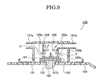
- the electrified fine particulate water generation device 106 used for the air conditioning apparatus 1 for the vehicle according to the third embodiment includes a lower side case 160a of a shallow lengthy box shape, an upper side case 160b of a shallow lengthy box shape fitted to the lower side case 160, a circuit storage part 163 disposed in an internal part of the lower side case 160a that houses circuits for control use and an electrified fine particulate water generation part 164 that generates electrified fine particulate water disposed in the same way in the internal part of the lower side case 160b.
- the upper side case 160b is made of a resin or the like.
- the upper side case 160b includes a cylindrical shaped air intake opening 161a in connection with the pipe conduit 151 of the upstream side connected to the wind propelling path 133 and a cylindrical shaped air discharge opening 161b in connection with the pipe conduit 152 of the downstream side connected to the side vent duct 141.
- the electrified fine particulate water generation part 164 includes a tube part 169 made of a resin or the like and constituting a main body, a mounting part 162 to the lower side case 160a disposed in a lower part of the tube part 169 integrally with the tube part 169, a fine pore 169a and etc. for air intake disposed in a side surface of the tube part 169, a negative electrode 167 of an internal part of the tube part, a water carrier part 167b disposed on the negative electrode 167 to protrude therefrom and a plus electrode 168 mounted on an upper end of the tube part 169.
- the tube part 169 is formed into a cylindrical shape and made of a resin or the like. Fine pores 169a, etc. are disposed consecutively in a circumferential direction with a proper interval in a side surface of the tube part 169.
- the tube part 169 is formed to be able to incorporate therein air from the air intake opening 161a at a proper wind velocity and a proper wind quantity.
- the negative electrode 167 is formed to have a disk shape made of a metal of aluminum or the like with an external circumference surface thereof fitted to an internal circumference surface of the tube part 169.
- the water carrier part 167b is formed to have a conical shape and made of a multi-porous material of ceramic or the like so that the condensed or bedewed water moves to a tip edge by capillarity and is disposed in a center of the negative electrode 167 to protrude therefrom so that a sufficient distance is maintained for insulation from the tube part 169 encircling a periphery.
- the plus electrode 168 is formed to a plate shape by metals or the like and is worked to have a circular ring shape with concentric circle shaped holes disposed therein.
- a Peltier device 165 that comes into contact with a back surface of the negative electrode 167 is disposed as a thermoelectric conversion device.
- a heat releasing fin 66 is mounted to a back surface of the Peltier device 165.
- the Peltier device 165 is formed to a plate shape by joining two kinds of metals.
- the Peltier device 165 is a plate shaped semiconductor device that utilizes a Peltier effect in which heat moves from one metal to the other when electrical current is applied to a joining part of the two kinds of metals.
- a side that comes into contact with the negative electrode 167 becomes a heat absorbing part
- another side that comes into contact with the heat releasing fin 166 becomes a heat releasing part.
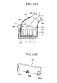
- the heat releasing fin 166 is formed by metals of aluminum or the like. As illustrated in FIG. 10B , a plurality of thin plate shaped blades are disposed to be approximately parallel on one side of the plate shaped base part to protrude therefrom so that a surface area becomes large. Thereby the heat releasing fin 166 is formed to be able to perform heat exchange efficiently and protrude from an inner wall surface of the internal and external air introduction part 134 of an upstream side of the fan 103.
- the electrified fine particulate water generation device 106 is mounted to an external surface of an opening and closing lid 181 used for a replacement of the filter 132, the heat releasing fin 166 is inserted to pass through a hole disposed on the opening and closing lid 181 so that together with engaging pieces 181a and 181a disposed on the opening and closing lid 181, the filter 132 is stopped in an engaged state.
- the pipe conduit 151 of the upstream side is connected as a circuitous pipe conduit to the side surface of the wind propelling path 133.
- the pipe conduit 151 of the upstream side is also connected to the side vent duct 141 via the electrified fine particulate water generation device 106 and the pipe conduit 152 of the downstream side.
- the wind propelling path 133 is disposed adjacent to a wind propelling blade 130 and etc. of the fan 103 for wind propelling use against the air conditioning unit 102. Therefore, the wind propelling path 133 has a high static pressure.
- a pressure gradient between the side vent duct 141 connected to an end thereof and the wind propelling path 133 becomes large.
- the side vent duct 141 is connected to the vehicle room interior with an approximately same static pressure with an atmosphere pressure.
- a static pressure of the wind propelling path 133 situated at the downstream side of the wind propelling blade 130 and etc. is extremely large. Therefore, by the pressure gradient between the both points, air flows from the wind propelling path 133 to the side vent duct 141.
- air flowed into the air intake opening 161a further flows into the electrified fine particulate water generation part 164 through the fine pores 169a and etc. disposed on the tube part 169.
- wind velocity can be further raised if the air passes through the fine pores 169a with a cross sectional area smaller than the pipe conduit 151 of the upstream side and the air intake opening 161a.
- the air having flowed into the electrostatic minute water generation part 164 with raised wind velocity passes through the internal part of the tube part 169 and is determined to pass through a periphery of the plus electrode 168 mounted on an upper edge of the tube part 169. At this moment, electrified fine particulate water sprayed in a mist state is contained between the water carrier part 167b and the plus electrode 168.
- the bedewing water is carried by capillarity from an elementary part to a tip edge part of the water carrier part 167b disposed on the negative electrode 167 to be projected therefrom.
- bedewing water carried to the tip edge part of the water carrier part 167b becomes the electrified fine particulate water sprayed towards the plus electrode 168 from a sharp tip edge part of the water carrier part 167b by a high voltage impressed between the negative electrode 167 and the plus electrode 168.
- heat release is performed by the heat releasing fin 166 disposed to come into contact with a back surface of the Peltier device 165. As illustrated in FIG. 10 , the heat releasing fin 166 protrudes from a wall surface of the internal and external air introduction part 134 connected to the wind propelling blade 130 and etc. of the fan 103. Therefore, it is not necessary to dispose an exclusive blast fan.
- the wind propelling blade 130 and etc. rotates so that a static pressure is lowered in a vicinity of an upstream side of the wind propelling blade 130 and etc. in comparison to a periphery thereof.
- Internal air 135 and external air 136 are introduced through the internal and external air introduction part 134 but by disposing the heat releasing fin 166 in a midway part of the introductory path, a wind quantity and a wind velocity necessary for cooling the heat releasing fin 166 can be obtained.
- the heat releasing fin 166 is projected from an internal wall surface of the internal and external air introduction part 134, a sufficient wind quantity can be wind propelled to the heat releasing fin 166 so that air does not stay or back flow and heat release can be performed efficiently.
- Air containing electrified fine particulate water in the above described manner is discharged to the pipe conduit 152 of a downstream side and further discharged to a side vent duct 141 through the pipe conduit 152 of the downstream side.
- Air discharged to the side vent duct 141 is eventually discharged into the vehicle room so that interior of the vehicle room can be sterile filtrated and odor eliminated.
- the air conditioning apparatus 100 for the vehicle according to the third embodiment does not require an exclusive blast fan but a wind quantity and a wind velocity sufficient to discharge the electrified fine particulate water can be obtained.
- a wind propelling path 133 with an extremely high static pressure is connected to a circuitous pipe conduit, that is, a pipe conduit 151 of the upstream side.
- a pressure gradient of the side vent duct 141 a wind quantity and a wind velocity can be made larger.
- the operating mode of the air conditioning apparatus 100 for the vehicle is constituted to three stages of Hi, Mid and Low
- a wind quantity and a wind velocity sufficient for the generation of the electrified fine particulate water can be obtained.
- the electrified fine particulate water generation device 106 and the side vent duct 141 are disposed to come into close contact, a distance until the generated electrified fine particulate water is discharged into the vehicle room becomes short so that an attenuation quantity of the electrified fine particulate water due to time lapse becomes small.
- the air containing electrified fine particulate water even in the case when the air conditioning apparatus 100 for the vehicle is operated at a wind propelling pattern that does not use the side vent duct 141, is blown out slightly from a grill.
- the circuitous pipe conduit 152 to the side vent duct 141 situated at both ends of an instrument panel, vehicle occupants are not blown directly so that sense of discomfort provided to the vehicle occupants is small.
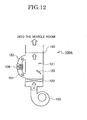
- the air conditioning apparatus 100A according to the fourth embodiment differs from a state of the third embodiment and includes a pipe conduit 151 of an upstream side and a pipe conduit 152 of a downstream side that connect an upstream side and a downstream side within a mix chamber 121 of an air conditioning unit 102.
- the air conditioning apparatus 100A for the vehicle includes a fan 103, an air conditioning unit 102 including a heat exchanger that heats and cools air wind propelled from the fan 103, a side vent duct 141 that discharges into the vehicle room air heated and cooled at the air conditioning unit 102.
- the pipe conduit 151 of the upstream side is disposed in an upstream side within the mix chamber 121 of the air conditioning unit 102.
- the pipe conduit 151 of the upstream side is connected to a downstream side within the same mix chamber 121 via an electrified fine particulate water generation device 106 and the pipe conduit 152 of the downstream side.
- an exclusive blast fan is not used. Regardless of whichever of the operating mode of the air conditioning apparatus 100A for the vehicle, electrified fine particulate water can be guided into the vehicle room.
- the air guided into the air conditioning unit 102 maintains a large static pressure in an upstream side of the mix chamber 121 of the air conditioning unit 102.
- a downstream side of the mix chamber 121 is connected to a side vent duct 141 and has a same static pressure with an atmosphere pressure.
- a housing part is attached to an opening part disposed in a wall surface of the duct.
- An electrified fine particulate water generation part of the electrified fine particulate water generation device is disposed in an internal part of the housing part.
- the housing part includes an intake opening and a discharge opening connected to an upstream side and a downstream side of the duct. Therefore, air flow and pressure differences thereof can be utilized.
- an exclusive blast fan is not disposed but electrified fine particulate water can discharged into an internal part of the duct.
- the housing part disposed with the electrified fine particulate water generation part is attached to an opening part of the duct so that an electrified fine particulate water generation device can be installed easily.
- the electrified fine particulate water generation part is disposed in the circuitous path connecting the intake opening and the discharge opening.
- a heat releasing fin is disposed in an internal part of the duct. Therefore, an exclusive blast fan is not disposed. However, by air flowing in the internal part of the duct, the heat releasing fin can be cooled efficiently.
- air flowing in the internal part of the duct is taken in from an intake opening so that a current is formed in the Venturi path.
- air is taken in from a part other than the opening part of the duct. The air is made to flow into a generation path disposed with the electrified fine particulate water generation part and a heat releasing path disposed with the heat releasing fin.
- the air conditioning apparatus for the vehicle of the present invention constituted as such is connected to a circuitous pipe conduit in connection with the duct at a high static pressure generation part of the fan.
- the electrified fine particulate water generation part is disposed in the circuitous pipe conduit.
- an exclusive blast fan is not disposed but the electrified fine particulate water can be discharged by a pressure gradient.
- a circuitous pipe conduit is connected to a vicinity of a wind propelling path in connection to a downstream side of the fan.
- a pressure force of a high static pressure generation part is utilized so that a necessary wind quantity can be possibly obtained.
- a circuitous pipe conduit in connection to a downstream part of the mix chamber is connected to an upstream part of the mix chamber of the air conditioning unit.
- the electrified fine particulate water generation part is disposed in an internal part of the circuitous pipe conduit. Regardless of whichever of an operating mode is the air conditioning apparatus being operated, the electrified fine particulate water can be guided into an interior of the vehicle room.
- a heat releasing fin of the thermal electric conversion device is configured to be protruded from an internal wall surface of an internal and external air introduction part of an upstream side of the fan so that an exclusive blast fan is not used but the heat releasing fin can be possibly cooled.
- the heat releasing fin 66 of the thermal electric conversion device 65 is not disposed in the internal part of the circuitous path 51.
- the heat releasing fin can be disposed in the internal part of the circuitous path 51.
- circuitous pipe conduit 51 is mounted to a hole disposed on a side surface of the wind propelling path 33.
- the circuitous pipe conduit 51 can be mounted to a hole disposed in a compartment partitioned by a bulkhead in which the bulkhead is disposed in an internal part of the wind propelling path 33.
- circuitous pipe conduit 51 is connected to the side vent duct 41.
- circuitous pipe conduit 51 can be connected to any duct of a center vent duct 42, a defroster duct and a foot duct or the like.
- the housing part 105 is attached to the side vent duct 141.
- the housing part 105 is attached to a separate duct of the center vent duct 142 or the like.
- the aspirator 109 is connected to the generation path 184 and the heat releasing path 185 so that the air can be taken in from a part differing to the duct 104.
- the air to be guided into is taken in from an intake opening for internal air and an intake opening for external air other than the part.
- the air conditioning apparatus for the vehicle according to the present embodiment is used for a vehicle but can also be widely used as an air conditioning apparatus for a house or a factory.
Landscapes
- Engineering & Computer Science (AREA)
- Mechanical Engineering (AREA)
- Air-Conditioning For Vehicles (AREA)
Abstract
Description
- The present invention relates to an air conditioning apparatus for a vehicle including a device to generate electrified fine particulate water.
- It is conventionally known to generate electrified fine particulate water having a minute particle diameter of about one nanometer through tens of nanometers, which is referred to as nano-ion mist by applying a voltage to plus and minus electrodes of an electrified fine particulate water generation device, as disclosed in
JP2005-131549A - In this case, it is usual to provide an exclusive blast fan in order to discharge the generated electrified fine particulate water, as disclosed in
JP2005-131549A - In addition, in
JP2005-131549 - When the electrodes are cooled by the Peltier device, heat is released using a heat releasing fin. However, it is necessary to supply wind to the heat releasing fin by use of the blast fan.
- However, in an apparatus as disclosed in
JP2005-131549A - In particular, in the case where the exclusive blast fan is used for an air conditioning apparatus for vehicle, because there is a limitation to a space for disposing the electrified fine particulate water generation device, it is necessary for the air conditioning apparatus for vehicle to be miniaturized.
- Therefore, an object of the present invention is to provide an air conditioning device for a vehicle that includes an electrified fine particulate water generation device having no an exclusive blast fan.
- To accomplish the above object, an air conditioning apparatus according to an embodiment of the present invention includes an air conditioning unit having a heat exchanger, a fan that sends air to the air conditioning unit, a duct to guide the air passing through the air conditioning unit into a vehicle room and an electrified fine particulate water generation device. A housing part is attached to an opening part disposed on a wall surface of the duct. The housing part includes an intake opening connected to an upstream side of the duct and a discharge opening connected to a downstream side of the duct. An electrified fine particulate water generation part of the electrified fine particulate water generation device is disposed inside the housing part.
- Hereby the electrified fine particulate water generation part is disposed in a circuitous path connecting the intake opening and the discharge opening. A heat releasing fin as a thermoelectric conversion device is disposed inside the duct and supplies moisture content in the air to the electrified fine particulate water generation part.
- In addition, the housing part includes a Venturi path that connects the intake opening and the discharge opening via a throat part, a generation path that takes in air from a differing part with the opening part and a heat releasing path in which the following constitution can be adopted. That is, the electrified fine particulate water generation part is disposed in the generation path. A downstream side of the generation path is connected to a vicinity of the throat part of the Venturi path. A heat releasing fin as the thermoelectric conversion device is disposed in the heat releasing path. The heat releasing fin supplies moisture content in the air to the electrified fine particulate water generation part. A downstream side of the heat releasing path can be connected to an internal part of the duct.
-
-
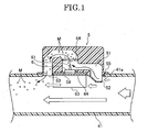
FIG. 1 is a schematic diagram illustrating a constitution about a vicinity of a housing part of an air conditioning apparatus for a vehicle according to a first embodiment of the present invention. -
FIG. 2 is a perspective view illustrating an entire constitution of the air conditioning apparatus for the vehicle according to the first embodiment of the present invention. -
FIG. 3 is a schematic diagram illustrating a constitution of an electrified fine particulate water generation device used for the air conditioning apparatus for the vehicle according to the first embodiment of the present invention. -
FIG. 4 is a schematic diagram illustrating a constitution of a vicinity of a housing part of an air conditioning apparatus for a vehicle according to a second embodiment of the present invention. -
FIG. 5 is a perspective view illustrating an approximate constitution of the air conditioning apparatus for the vehicle according to the second embodiment of the present invention. -
FIG. 6 is a perspective view illustrating an entire constitution of the air conditioning apparatus for the vehicle according to a third embodiment of the present invention. -
FIG. 7A is a schematic diagram illustrating a constitution of an electrified fine particulate water generation device used for the air conditioning apparatus for the vehicle according to the third embodiment of the present invention and specifically, a perspective view of a dismantled state. -
FIG. 7B is a schematic diagram illustrating a constitution of an electrified fine particulate water generation device used for the air conditioning apparatus for the vehicle according to the third embodiment of the present invention and specifically, a perspective view of a completed state. -
FIG. 8 is a perspective view illustrating a constitution of an electrified fine particulate water generation part of an electrified fine particulate water generation device used for the air conditioning apparatus for the vehicle according to the third embodiment of the present invention. -
FIG. 9 is a cross sectional diagram of the electrified fine particulate water generation device viewed from a direction of arrow A-A ofFIG. 7B . -
FIG. 10A is a schematic diagram illustrating a constitution of a fan used for the air conditioning apparatus for the vehicle according to the above described third embodiment and specifically, a cross sectional diagram illustrating a mounting position of a heat releasing fin. -
FIG. 10B is a schematic diagram illustrating a constitution of a fan used for the air conditioning apparatus for the vehicle according to the above described third embodiment and specifically, a perspective view illustrating an opening and closing lid. -
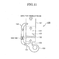
FIG. 11 is a schematic diagram illustrating a connecting position of the electrified fine particulate water generation device used for the air conditioning apparatus for the vehicle of the above described third embodiment. -
FIG. 12 is a schematic diagram illustrating a connecting position of an electrified fine particulate water generation device used for an air conditioning apparatus for a vehicle according to a fourth embodiment of the present invention. - A best mode of the present invention will be described in detail hereinafter with reference to the accompanying drawings with regard to several embodiments specifying this mode.
- First, with regard to
FIG. 2 , an air conditioning apparatus for a vehicle according to a first embodiment of the present invention is described. - As illustrated in
FIG. 2 , the air conditioning apparatus 1 for the vehicle in the first embodiment includes afan 3, anair conditioning unit 2 provided with a heat exchanger for heating and cooling air wind propelled from thefan 3,side vent ducts center vent ducts - The
fan 3 includes an internal and external air introduction part (not illustrated) that takes in air internal and external to the vehicle room, a filter (not illustrated) to filter air and also, wind propelling blades (not illustrated). Thefan 3 is a so called sirocco fan type. Therefore, a high static pressure can be secured when supplying wind and it is characteristic that a certain wind propelling quantity can be secured even when a high static pressure is applied. - In addition, inside the
air conditioning unit 2, as illustrated inFIG. 5 , anevaporator 21 and aheater 22 are disposed as heat exchangers for cooling and heating the air wind propelled from thefan 3 so that the air can be mixed at a mix chamber and adjusted to an optimum temperature to be wind propelled towards a vehicle room side. - Furthermore, as illustrated in
FIG. 2 , theside vent ducts center vent ducts air conditioning unit 2 with an interior of the vehicle room so that the air adjusted to an optimum temperature at theair conditioning unit 2 can be efficiently introduced into the vehicle room. Theside vent ducts center vent ducts - As illustrated in
FIG. 1 andFIG. 2 , in the air conditioning apparatus 1 for the vehicle of the present embodiment, anopening part 41a is provided in an upper wall surface of one of theside vent ducts 41. Ahousing 5 mounted with an electrified fine particulatewater generation device 6 is attached to theopening part 41a. - A lower end of the
housing part 5 is formed with an approximately same shape to a planar view shape of theopening part 41a to be fitted on theopening part 41a. A thrown outledge part 55 is constituted in a periphery of the lower end to engage a periphery of theopening part 41a. Theopening part 41a of theside vent duct 41 is closed by attaching thehousing part 5. - In addition, in the
housing part 5, as illustrated inFIG. 1 , acircuitous path 51 is formed to tortuously connect anintake opening 52 and adischarge opening 53. - The
intake opening 52 is provided to be protruded towards an internal part of theside vent duct 41 and opens towards an upstream side (a side of the air conditioning unit 2). A surface of the opening is approximately orthogonal to a direction of air flow (a direction of a white arrow ofFIG. 1 ) within theside vent duct 41. - In addition, the
discharge opening 53 is configured to open towards a center of a cross section of theside vent duct 41. A surface of the opening is approximately parallel to the direction of air flow (the direction of the white arrow ofFIG. 1 ) within theside vent duct 41. - Furthermore, the
circuitous path 51, for example, as illustrated inFIG. 1 , extends from theintake opening 52 toward theside vent duct 41 outwardly and is bent. After extending approximately parallel to a stretching direction of theside vent duct 41, thecircuitous path 51 is bent at anopening 54 for attachment of the later described electrified fine particulatewater generation device 6 and again extends outwardly. Hereby thecircuitous path 51 is formed to turn back towards thedischarge opening 53. - An opening connecting the
circuitous path 51 and the internal part of theside vent duct 41 is formed as theopening 54 for attachment disposed midst thecircuitous path 51. Theopening 54 for attachment is used for attaching the electrified fine particulatewater generation device 6. - The electrified fine particulate
water generation device 6, as illustrated inFIG. 3 , is mainly constituted from an electrified fine particulatewater generation part 61 for generating electrified fine particulate water M, a Peltier device as a thermoelectric conversion device which supplies moisture content in the air to the electrified fine particulatewater generation part 61, aheat releasing fin 63 for cooling the Peltier device and an insulatingplate 64 for sealing theopening 54 for attachment. - The electrified fine particulate
water generation part 61 is mainly constituted from a plate shaped discharge electrode 61a having a water carrier part 61b protruded therefrom, anopposite electrode 61c disposed at a position separated from a tip edge of the water carrier part 61b. - The discharge electrode 61a is disposed on an upper surface side of the insulating
plate 64, formed to have a rectangular shape as viewed in plan and made of a metal of aluminum or the like. - In addition, the water carrier part 61b is disposed at an approximate center of the discharge electrode 61a to be protruded therefrom and formed to have a conical shape using porous materials of ceramic or the like so that dew-condensed water moves to the tip edge by capillarity.
- Furthermore, the
opposite electrode 61c is worked to an annular disk shape disposed with concentric circle shaped holes by metals or the like. - The discharge electrode 61a and the
opposite electrode 61c are connected to a high voltage impressing part 71 receiving power supply from an electricalpower control part 7. A high voltage is applied in a way that a side of the discharge electrode 61a becomes a minus electrode. - The
Peltier device 62 having an approximate same shape as viewed in planar as the discharge electrode 61a is disposed to come into contact with a back surface of the discharge electrode 61a. Aheat releasing fin 63 is mounted on a back surface of thePeltier device 62. - The
Peltier device 62 is formed into a plate shape by joining two kinds of metals. When electrical current is applied from the electricalpower control part 7 to a joining part of the two kinds of metals, a Peltier effect is present in which heat moves one the metal to the other. The Peltier device is a plate shaped semiconductor device that utilizes such Peltier effect. In the Peltier device of the present embodiment, a side that comes into contact with the discharge electrode 61a is formed to be a heat absorbing part, the other side that comes into contact with theheat releasing fin 63 is formed to be a heat releasing part. - In addition, a rectangular shaped opening that connects the side of the discharge electrode 61a and a side of the
heat releasing fin 63 with thePeltier device 62 housed therein is disposed in the insulatingplate 64. - On one hand, the
heat releasing fin 63 is made of a metal of aluminum or the like. As illustrated inFIG. 3 , a plurality of approximate parallel thin plate shaped blades is disposed on one surface side of a plate shaped base part of theheat releasing fin 63 to be protruded therefrom so that a surface area thereof becomes large and theheat releasing fin 63 is formed to be able to perform heat exchange efficiently. - In order for each of the thin plate shaped blades of the
heat releasing fin 63 to be wind propelled uniformly, as illustrated inFIG. 1 , a surface of each of the blade is shaped to be parallel to a direction of air flow. Theheat releasing fin 63 is disposed to be protruded from theopening 54 for attachment towards the internal part of theside vent duct 41. - On the other hand, when the
heat releasing fin 63 is mounted on theopening 54 for attachment in such a direction, the electrified fine particulatewater generation part 61 is disposed to protrude therefrom towards an internal part of thecircuitous path 51. - In addition, a portion of the air flowing in the internal part of the
side vent duct 41 is taken in from theintake opening 52 of thecircuitous path 51 to be supplied to the electrified fine particulatewater generation part 61 and carried together with the electrified fine particulate water M generated thereof to thedischarge opening 53 so that the electrified fine particulate water M is discharged to the internal part of theside vent duct 41. - Next, operations of the air conditioning apparatus 1 for the vehicle of the above embodiment are described.
- In the air conditioning apparatus 1 for the vehicle of the above described constitution, as illustrated in
FIG. 1 , thehousing part 5 is attached to theopening part 41a disposed in the upper wall surface of theside vent duct 41. The electrified fine particulatewater generation part 61 of the electrified fine particulatewater generation device 6 is disposed in the internal part of thecircuitous path 51 of thehousing part 5. - The
housing part 5 includes anintake opening 52 and adischarge opening 53 respectively connected to an upstream side and a downstream side of theside vent duct 41. Air can be taken into thecircuitous path 51 by utilizing air flows in the internal part of theside vent duct 41 and pressure force differences between theintake opening 52 and thedischarge opening 53. - Therefore, an exclusive blast fan is not disposed. However, the electrified fine particulate water M is discharged to the internal part of the
side vent duct 41 and can be discharged into the vehicle room therefrom. - That is, when air is taken in from the
intake opening 52, air flow until thedischarge opening 53 is formed along thecircuitous path 51. - The
circuitous path 51 is tortuous. Air flows at a speed differing from a wind velocity of the internal part of theside vent duct 41. - In addition, air containing moisture content flows into the electrified fine particulate
water generation part 61 and passes through a hole at a center of theopposite electrode 61c. At this moment, electrified fine particulate water M sprayed in a mist state between the water carrier part 61b and theopposite electrode 61c is mixed. - Air flow is formed in one direction of the
circuitous path 51. Air passing therethrough does not stay or back flow. Therefore, electrified fine particulate water M sprayed in a mist state from the water carrier part 61b can be efficiently attracted. - Hereby a generation mechanism of the electrified fine particulate water M is approximately described.
- First, by being energized by the
Peltier device 62 as illustrated inFIG. 3 , a surface of thePeltier device 62 facing the discharge electrode 61a is cooled so that the discharge electrode 61a coming into contact with thePeltier device 62 is cooled. As a result, dew-condensed water is generated on the surface of the discharge electrode 61a. - The bedewing water is carried by capillarity from an elementary part to a tip edge part of the water carrier part 61b disposed on the discharge electrode 61a to be projected therefrom.
- In addition, condensed water carried to the tip edge part of the water carrier part 61b becomes the electrified fine particulate water M sprayed towards the
opposite electrode 61c from a sharp tip edge part of the water carrier part 61b by a high voltage impressed between the discharge electrode 61a and theopposite electrode 61c - Hereby, in order to generate the bedewing water, heat release is performed by the
heat releasing fin 63 disposed to come into contact with the back surface of thePeltier device 62. As illustrated inFIG. 1 , theheat releasing fin 63 is protruded to the internal part of theside vent duct 41. Therefore, a wind quantity necessary for cooling theheat releasing fin 63 can be obtained even when an exclusive blast fan is not disposed. - That is, because the
heat releasing fin 63 is protruded from theopening part 41a towards the internal part of theside vent duct 41, a sufficient quantity of wind can be wind propelled to theheat releasing fin 63 so that the air does not stay or back flow and heat release can be performed efficiently. - In addition, by cooling the
heat releasing fin 63, through a heat releasing surface of thePeltier device 62 that comes into contact with a front surface side of theheat releasing fin 63, heat release of thePeltier device 62 is facilitated and heat exchange can be performed more efficiently. - As mentioned above, the air containing electrified fine particulate water M in such a way, as illustrated in
FIG. 1 , is discharged into the internal part of theside vent duct 41 from the discharge opening 53 of thecircuitous path 51. - Then air discharged into the
side vent duct 41 is eventually discharged into the vehicle room to accomplish sterile filtrate and odor elimination in the vehicle room. - The electrified fine particulate water M discharged from the electrified fine particulate
water generation device 6 has little attenuations due to time lapse. Therefore, the electrified fine particulate water M discharged into the vehicle room from an outlet of theside vent duct 41 can be diffused to the entire vehicle room. - In addition, if the electrified fine particulate
water generation device 6 is disposed in a duct close to the vehicle room such as theside vent duct 41, attenuations in the internal part of the air conditioning device 1 for the vehicle can be suppressed to a minimum. - Furthermore, if a constitution is adopted in which a
housing part 5 is directly mounted to theopening part 41a of a duct such as theside vent duct 41 or the like, easy installation is possible for air conditioning apparatuses of various states without much modifications. - That is, if the electrified fine particulate
water generation device 6 is mounted to theopening 54 for attachment of thehousing part 5, it is only necessary to attach thehousing part 5 to theopening part 41a open at the upper wall surface of theside vent duct 41. Disposition of the electrified fine particulatewater generation device 6 is thereby complete. - In such a way, in the air conditioning apparatus 1 of the present embodiment, a wind quantity and a wind speed sufficient to discharge the electrified fine particulate water M can be obtained by a simple constitution in which an exclusive blast fan is not disposed.
- In addition, the
housing part 5 is disposed in an external part of theside vent duct 41. Therefore, there is no limitation to shapes thereof and an easily moldable shape can be adopted. - An air conditioning apparatus for a vehicle according to a second embodiment of the present invention is described hereinafter with reference to
FIG. 4 andFIG. 5 . In addition, descriptions of parts with the same or equivalent content to the previous embodiment are described using the same numerals. - An
air conditioning apparatus 1A for a vehicle in the second embodiment not only utilizes air flowing in an internal part of theside vent duct 41 as illustrated in the first embodiment but also utilizes air from other parts. - The
air conditioning apparatus 1A, as illustrated inFIG. 5 includes afan 3, anair conditioning unit 2 provided with a heat exchanger for heating and cooling air wind propelled from thefan 3, side vent ducts as well as center vent ducts or the like as aduct 4 for discharging the cooled air into a vehicle room. - In an internal part of the
air conditioning unit 2, anevaporator 21 and aheater 22 are disposed. Air wind propelled from thefan 3 is cooled and heated to be mixed at a mix chamber so that the air can be adjusted to an optimum temperature and wind propelled into the vehicle room. - On one hand, on a wall surface of the
duct 4, anopening part 4a as illustrated inFIG. 4 is disposed. Ahousing part 8 mounted with the electrified fine particulatewater generation device 6 is attached to theopening part 4a. - A lower end of the
housing part 8 of the present embodiment is formed with an approximately same shape to a plan-view shape of theopening part 4a to be fitted on theopening part 4a. A thrown outledge part 87 is provided in a periphery of the lower end to engage a periphery of theopening part 4a. - In the
housing part 8, as illustrated inFIG. 4 , aVenturi path 81 is formed to connect anintake opening 82 and adischarge opening 83. - A
throat part 81a having a cross section smaller than cross sections of theintake opening 82 and thedischarge opening 83 at both ends of a flow path is formed as theVenturi path 81. A wind speed passing through theVenturi path 81a is faster than a wind speed during intake at theintake opening 82. Therefore, from Bernoulli's theorem, a pressure of thethroat part 81a becomes low. - On the other hand, a surface of the
housing part 8 at a downstream side of the air flow of theduct 4 is open for air intake from parts differing to theopening part 4a. - At the opening, a
generation path 84 with the electrified fine particulatewater generation part 61 disposed therein is connected to aheat releasing path 85 disposed with aheat releasing fin 63 of thePeltier device 62. ThePeltier device 62 is configured to supply moisture content in the air to the electrified fine particulatewater generation part 61. - The
generation path 84, after extended in an approximately parallel way in a stretching direction of theduct 4, is bent at anopening 86 for attachment of the electrified fine particulatewater generation device 6 to be connected to a downstream side of thethroat part 81a of theVenturi path 81. - In addition, the
heat releasing path 85 is formed in a separate path with thegeneration path 84 and connected to the discharge opening 83 of theVenturi path 81. - In addition, the electrified fine particulate
water generation device 6 is mounted to theopening 86 for attachment in such a way that the electrified fine particulatewater generation part 61 is disposed in thegeneration path 84, and theheat releasing fin 63 is disposed in theheat releasing path 85. - At this moment, an
opposite electrode 61c of the electrified fine particulatewater generation part 61 is disposed at aconnection opening 88 between theVenturi path 81 and thegeneration path 84. In addition, theopening 86 for attachment is closed by an insulatingplate 64 of the electrified fine particulatewater generation device 6. Pathways of thegeneration path 84 and theheat releasing path 85 are separated. - In addition, by the aforementioned Bernoulli's theorem, air from the
generation path 84 can easily flow into thethroat part 81a of a low pressure so that an air flow stronger than theheat releasing path 85 can be formed. - Hereby as illustrated in
FIG. 5 , asmall diameter pipe 92 of anaspirator 9 is connected to thegeneration path 84 and theheat releasing path 85. - The
aspirator 9 is necessary for an air conditioning device that performs automatic temperature adjustment. Air within the vehicle room is guided into anintake opening 91 for internal air using Bernoulli's theorem. A sensor for temperature detection (not illustrated) disposed in the internal part detects temperatures within the vehicle room. - In addition, the
aspirator 9 is formed to have a pipe line shape by alarge diameter pipe 93 of a side of theintake opening 91 for internal air and asmall diameter pipe 92 connected therewith. Theaspirator 9 incorporates air inside the vehicle room from theintake opening 91 of the internal air disposed for example, at a side or the like of a steering of an instrument panel. - Therefore, by connecting end parts of the
generation path 84 and theheat releasing path 85 to theaspirator 9, air can be taken in from a part differing to theduct 4 - Then, by the air taken in from the
aspirator 9, generation of the electrified fine particulate water M is performed at thegeneration path 84 and cooling of theheat releasing fin 63 is performed at theheat releasing path 85. - Next, operations of the above described
air conditioning apparatus 1A are described. - In the
air conditioning apparatus 1A constituted as above, air flowing in the internal part of theduct 4 is taken in from anintake opening 82 to form an air flow in theVenturi path 81. - On the other hand, air is taken in from the
aspirator 9. The air is made to flow into thegeneration path 84 disposed with the electrified fine particulatewater generation part 61 and theheat releasing path 85 disposed with theheat releasing fin 63. - By connecting the
generation path 84 to a downstream side of thethroat part 81a of theVenturi path 81, electrified fine particulate water M generated at thegeneration path 84 keeps up with the air flow of theVenturi path 81 to be discharged from thedischarge opening 83. - That is, the
generation path 84 is connected to a vicinity of thethroat part 81a at which wind velocity of theVenturi part 81 becomes fastest. The electrified fine particulate water M having flowed into theVenturi path 81 from the connection opening 88 of thegeneration path 84 can be efficiently carried to thedischarge opening 83. - By disposing the
Venturi path 81 in such a way, without being largely affected by the wind velocity or static pressure of the internal part of theduct 4, air flow of a quantity necessary for discharging the electrified fine particulate water M can be formed. - In addition, air that flows to the
generation path 84 and theheat releasing path 85 can be secured from a part other than theopening part 4a of theduct 4 so that a wind quantity can be secured without being largely affected by the wind quantity or static pressure of the internal part of theduct 4. - Furthermore, because air flowing in the internal part of the
duct 4 is air dehumidified by theevaporator 21, by taking-in air containing more moisture content than that and flowing the air into thegeneration path 84, condensed water is generated certainly and a state is easily maintained to possibly continuously generate the electrified fine particulate water M. - In addition, other constitutions and operational effects of the air conditioning apparatus for the vehicle according to the second embodiment of the present invention are abbreviated for description because they are approximately the same to the air conditioning apparatus for the vehicle according to the first embodiment.
- Next, an air conditioning apparatus for a vehicle according to the third embodiment of the present invention is described.
- As illustrated in
FIG. 6 , theair conditioning apparatus 100 of the third embodiment includes afan 103, anair conditioning unit 102 that includes a heat exchanger for heating and cooling air wind propelled from thefan 103,side vent ducts center vent ducts air conditioning unit 102. - The
fan 103, as illustrated inFIG. 7A , includes an internal and externalair introduction part 134 that introducesinternal air 135 within the vehicle room andexternal air 136 outside the vehicle room, afilter 132 that filtrate air having passed through the internal and externalair introduction part 134,wind propelling blades 130 rotated by awind propelling motor 131 and etc., ascroll casing 137 that houses thewind propelling blades 130 and the etc. as well as awind propelling path 133 that sends air urged by the rotatingwind propelling blades 130 and the etc. to theair conditioning unit 102. - The internal and external
air introduction part 134 is connected to a duct (not illustrated) going in and out of the vehicle room. Theintroduction part 134 can introduce theinternal air 135 or theexternal air 136 or mixed air of the internal and external air. - In addition, the
filter 132 is disposed downstream of the internal and externalair introduction part 134 to remove powder dust, pollen and exhaust gas of the air to be introduced. - In addition, the
wind propelling blades 130 and etc. are disposed at an equal distance from a rotating shaft. Thewind propelling blades 130 are so called sirocco fan type that rotates with a cylindrical shaped constitution. Theblast fan 130 and etc. is formed to be able to urge the air in a radial fashion by a centrifugal force from between thewind propelling blades 130 and etc.. - In addition, because the
fan 103 is a sirocco fan type, a high static voltage can be secured when propelling wind, in addition, a constant wind propelling quantity can be secured even when a high static voltage is operative. - Furthermore, the
scroll casing 137 has a circular shaped cross section. The scroll casing housing thewind propelling blade 130 and etc. is disposed at anopening 138 connected to awind propelling path 133 in a part of a cross section of a side of theair conditioning unit 2. - As illustrated in
FIG. 6 andFIG. 10A , thewind propelling path 133 is disposed adjacent to thewind propelling blade 130 and etc. and formed to be able to send air to theair conditioning unit 102 without damaging a static pressure of the air having a high static pressure. - In addition, with regard to a cross sectional shape of the wind propelling path, a height of up and down directions of the vehicle are formed to be approximately the same to the
wind propelling blade 130 and etc., a width of front and rear directions of the vehicle are formed to be approximately the same to a width of theopening 138 disposed on thescroll casing 135. - In addition, the
air conditioning unit 102, as illustrated inFIG. 11 , includes in the internal part thereof anevaporator 122 and aheater 125 as heat exchangers. Air wind propelled from thefan 103 is cooled, heated and mixed at amix chamber 121 so that the air can be adjusted to an optimum temperature and wind propelled into the vehicle room. - Furthermore, as illustrated in
FIG. 6 , theside vent ducts center vent ducts air conditioning unit 102, connects an air outlet of theair conditioning unit 102 with vehicle room interior and are formed with a predetermined cross sectional area to have a smooth internal surface. - As illustrated in
FIG. 6 , in theair conditioning apparatus 100 for the vehicle of the present embodiment, apipe conduit 151 of an upstream side is connected as a circuitous path to a side surface of thewind propelling path 133 in the vicinity ofwind propelling blades 130 and etc. Thepipe conduit 151 is connected to theside vent duct 141 via the electrified fine particulatewater generation device 106 and apipe conduit 152 of a downstream side. - The
pipe conduit 151 of the upstream side is formed, for example, by a hose of an internal diameter ϕ of 16 mm or the like. One end thereof is connected to a mounting hole disposed in a side surface of thewind propelling path 133. Another end thereof is connected to anair intake opening 161a of the electrified fine particulate water generation device 106 (refer toFIG. 7A ). - In addition, the
pipe conduit 151 at the upstream side may be formed integrally with thefan 103 by a resin or the like to facilitate an assembly and a handling of theair condition apparatus 100 for the vehicle. - In addition, a
pipe conduit 152 of a downstream side is formed to have a same diameter and material with thepipe conduit 151 of the upstream side. One end thereof is connected to anair discharge opening 161b of the electrified fine particulate water generation device 106 (seeFIG. 7A ). Another end thereof is connected to a mounting provided in a side surface of a midway part of theside vent duct 141. - Then, as illustrated in
FIG. 7A and FIG. 7B , the electrified fine particulatewater generation device 106 used for the air conditioning apparatus 1 for the vehicle according to the third embodiment includes alower side case 160a of a shallow lengthy box shape, anupper side case 160b of a shallow lengthy box shape fitted to the lower side case 160, acircuit storage part 163 disposed in an internal part of thelower side case 160a that houses circuits for control use and an electrified fine particulatewater generation part 164 that generates electrified fine particulate water disposed in the same way in the internal part of thelower side case 160b. - The
upper side case 160b is made of a resin or the like. In a vicinity of electrified fine particulatewater generation part 164 of the internal part of thelower side case 160a, theupper side case 160b includes a cylindrical shapedair intake opening 161a in connection with thepipe conduit 151 of the upstream side connected to thewind propelling path 133 and a cylindrical shapedair discharge opening 161b in connection with thepipe conduit 152 of the downstream side connected to theside vent duct 141. - As illustrated in
FIG. 8 andFIG. 9 , the electrified fine particulatewater generation part 164 includes atube part 169 made of a resin or the like and constituting a main body, a mountingpart 162 to thelower side case 160a disposed in a lower part of thetube part 169 integrally with thetube part 169, afine pore 169a and etc. for air intake disposed in a side surface of thetube part 169, anegative electrode 167 of an internal part of the tube part, awater carrier part 167b disposed on thenegative electrode 167 to protrude therefrom and aplus electrode 168 mounted on an upper end of thetube part 169. - The
tube part 169 is formed into a cylindrical shape and made of a resin or the like.Fine pores 169a, etc. are disposed consecutively in a circumferential direction with a proper interval in a side surface of thetube part 169. Thetube part 169 is formed to be able to incorporate therein air from theair intake opening 161a at a proper wind velocity and a proper wind quantity. - In addition, the
negative electrode 167 is formed to have a disk shape made of a metal of aluminum or the like with an external circumference surface thereof fitted to an internal circumference surface of thetube part 169. - In addition, the
water carrier part 167b is formed to have a conical shape and made of a multi-porous material of ceramic or the like so that the condensed or bedewed water moves to a tip edge by capillarity and is disposed in a center of thenegative electrode 167 to protrude therefrom so that a sufficient distance is maintained for insulation from thetube part 169 encircling a periphery. - Furthermore, the
plus electrode 168, as illustrated inFIG. 8 , is formed to a plate shape by metals or the like and is worked to have a circular ring shape with concentric circle shaped holes disposed therein. - As illustrated in
FIG. 9 , in the electrified fine particulatewater generation device 106 used for the air conditioning apparatus 1 for the vehicle of the present embodiment, aPeltier device 165 that comes into contact with a back surface of thenegative electrode 167 is disposed as a thermoelectric conversion device. A heat releasing fin 66 is mounted to a back surface of thePeltier device 165. - The
Peltier device 165 is formed to a plate shape by joining two kinds of metals. ThePeltier device 165 is a plate shaped semiconductor device that utilizes a Peltier effect in which heat moves from one metal to the other when electrical current is applied to a joining part of the two kinds of metals. In the present embodiment, a side that comes into contact with thenegative electrode 167 becomes a heat absorbing part, another side that comes into contact with theheat releasing fin 166 becomes a heat releasing part. - In addition, the
heat releasing fin 166 is formed by metals of aluminum or the like. As illustrated inFIG. 10B , a plurality of thin plate shaped blades are disposed to be approximately parallel on one side of the plate shaped base part to protrude therefrom so that a surface area becomes large. Thereby theheat releasing fin 166 is formed to be able to perform heat exchange efficiently and protrude from an inner wall surface of the internal and externalair introduction part 134 of an upstream side of thefan 103. - At this moment, as illustrated in
FIG. 9 ,FIG. 10A and FIG. 10B , the electrified fine particulatewater generation device 106 is mounted to an external surface of an opening and closinglid 181 used for a replacement of thefilter 132, theheat releasing fin 166 is inserted to pass through a hole disposed on the opening and closinglid 181 so that together with engagingpieces lid 181, thefilter 132 is stopped in an engaged state. - Next, operations of the
air conditioning apparatus 100 for the vehicle according to the above described third embodiment are described. - In the
air conditioning apparatus 100 for the vehicle configured as described above, as illustrated inFIG. 6 andFIG. 11 , thepipe conduit 151 of the upstream side is connected as a circuitous pipe conduit to the side surface of thewind propelling path 133. Thepipe conduit 151 of the upstream side is also connected to theside vent duct 141 via the electrified fine particulatewater generation device 106 and thepipe conduit 152 of the downstream side. - Therefore, it is not necessary to dispose an exclusive blast fan to the electrified fine particulate
water generation device 100. However, a wind quantity and a wind velocity sufficient for generating electrified fine particulate water can be obtained. - That is, the
wind propelling path 133 is disposed adjacent to awind propelling blade 130 and etc. of thefan 103 for wind propelling use against theair conditioning unit 102. Therefore, thewind propelling path 133 has a high static pressure. By connecting thepipe conduit 151 of the upstream side to thewind propelling path 133, a pressure gradient between theside vent duct 141 connected to an end thereof and thewind propelling path 133 becomes large. - That is, the
side vent duct 141 is connected to the vehicle room interior with an approximately same static pressure with an atmosphere pressure. In comparison, a static pressure of thewind propelling path 133 situated at the downstream side of thewind propelling blade 130 and etc. is extremely large. Therefore, by the pressure gradient between the both points, air flows from thewind propelling path 133 to theside vent duct 141. - Air flowing from the
wind propelling path 133 to thepipe conduit 151 of the upstream side flows into theair intake opening 161a of the electrified fine particulatewater generation device 106. - Next, as illustrated in
FIG. 9 , air flowed into theair intake opening 161a further flows into the electrified fine particulatewater generation part 164 through thefine pores 169a and etc. disposed on thetube part 169. - At this moment, wind velocity can be further raised if the air passes through the
fine pores 169a with a cross sectional area smaller than thepipe conduit 151 of the upstream side and theair intake opening 161a. - The air having flowed into the electrostatic minute
water generation part 164 with raised wind velocity passes through the internal part of thetube part 169 and is determined to pass through a periphery of theplus electrode 168 mounted on an upper edge of thetube part 169. At this moment, electrified fine particulate water sprayed in a mist state is contained between thewater carrier part 167b and theplus electrode 168. - Because the wind velocity passing through is fast, the passing air does not stay or back flow, electrified fine particulate water M sprayed in a mist state from the
water carrier part 167b can be efficiently attracted. - Hereby a generation mechanism of the electrified fine particulate water is approximately described.
- First, by being energized by the
Peltier device 165, a face of thePeltier device 165 facing thenegative electrode 167 is cooled so that thenegative electrode 167 coming into contact with thePeltier device 165 is cooled. As a result, bedewing water is generated on the surface of thenegative electrode 167. - Next, the bedewing water is carried by capillarity from an elementary part to a tip edge part of the
water carrier part 167b disposed on thenegative electrode 167 to be projected therefrom. - In addition, bedewing water carried to the tip edge part of the
water carrier part 167b becomes the electrified fine particulate water sprayed towards theplus electrode 168 from a sharp tip edge part of thewater carrier part 167b by a high voltage impressed between thenegative electrode 167 and theplus electrode 168. - In addition, in order to generate the bedewed water, heat release is performed by the
heat releasing fin 166 disposed to come into contact with a back surface of thePeltier device 165. As illustrated inFIG. 10 , theheat releasing fin 166 protrudes from a wall surface of the internal and externalair introduction part 134 connected to thewind propelling blade 130 and etc. of thefan 103. Therefore, it is not necessary to dispose an exclusive blast fan. - That is, in an internal part of the
fan 103, thewind propelling blade 130 and etc. rotates so that a static pressure is lowered in a vicinity of an upstream side of thewind propelling blade 130 and etc. in comparison to a periphery thereof.Internal air 135 andexternal air 136 are introduced through the internal and externalair introduction part 134 but by disposing theheat releasing fin 166 in a midway part of the introductory path, a wind quantity and a wind velocity necessary for cooling theheat releasing fin 166 can be obtained. - That is, because the
heat releasing fin 166 is projected from an internal wall surface of the internal and externalair introduction part 134, a sufficient wind quantity can be wind propelled to theheat releasing fin 166 so that air does not stay or back flow and heat release can be performed efficiently. - By cooling the
heat releasing fin 166, through a heat releasing surface of thePeltier device 165 that comes into contact with a front surface side of theheat releasing fin 166, heat release of thePeltier device 165 is facilitated and heat exchange can be performed efficiently. - Air containing electrified fine particulate water in the above described manner is discharged to the
pipe conduit 152 of a downstream side and further discharged to aside vent duct 141 through thepipe conduit 152 of the downstream side. - Air discharged to the
side vent duct 141 is eventually discharged into the vehicle room so that interior of the vehicle room can be sterile filtrated and odor eliminated. - As described above, the
air conditioning apparatus 100 for the vehicle according to the third embodiment does not require an exclusive blast fan but a wind quantity and a wind velocity sufficient to discharge the electrified fine particulate water can be obtained. - That is, a
wind propelling path 133 with an extremely high static pressure is connected to a circuitous pipe conduit, that is, apipe conduit 151 of the upstream side. By a pressure gradient of theside vent duct 141, a wind quantity and a wind velocity can be made larger. - In this case, a static pressure of the
wind propelling path 133 that comes into close contact with thefan 103 is large. Therefore, a predetermined wind quantity and wind velocity can be obtained whatever an operating mode of theair conditioning apparatus 100 for the vehicle. - For example, in the case the operating mode of the
air conditioning apparatus 100 for the vehicle is constituted to three stages of Hi, Mid and Low, in the case when the operating mode is Low, a wind quantity and a wind velocity sufficient for the generation of the electrified fine particulate water can be obtained. - In addition, in the third embodiment, as illustrated in
FIG. 6 , by disposing the electrified fine particulatewater generation device 106 in a midpoint of a straight line connecting thewind propelling path 133 and theside vent duct 141, a distance between thewind propelling path 133 and theside vent duct 141 becomes short so that damages of a static pressure obtained at thewind propelling path 133 can be made smaller and a pressure gradient can be made larger. - In addition, because the electrified fine particulate
water generation device 106 and theside vent duct 141 are disposed to come into close contact, a distance until the generated electrified fine particulate water is discharged into the vehicle room becomes short so that an attenuation quantity of the electrified fine particulate water due to time lapse becomes small. - In addition, the air containing electrified fine particulate water, even in the case when the
air conditioning apparatus 100 for the vehicle is operated at a wind propelling pattern that does not use theside vent duct 141, is blown out slightly from a grill. In this case also, by connecting thecircuitous pipe conduit 152 to theside vent duct 141 situated at both ends of an instrument panel, vehicle occupants are not blown directly so that sense of discomfort provided to the vehicle occupants is small. - As described above, because generated electrified fine particulate water can be efficiently guided into a vehicle room, sterile filtration and odor elimination can be performed efficiently in the interior of the vehicle room by the electrified fine particulate water.
- Hereinafter, with reference to
FIG. 12 , the air conditioning apparatus for the vehicle according to the fourth embodiment of the present invention is described. - In addition, for the air conditioning apparatus for the vehicle according to the fourth embodiment, descriptions of parts uniform or the same to the air conditioning apparatus for the vehicle of the third embodiment are made with the same reference numerals.
- The
air conditioning apparatus 100A according to the fourth embodiment differs from a state of the third embodiment and includes apipe conduit 151 of an upstream side and apipe conduit 152 of a downstream side that connect an upstream side and a downstream side within amix chamber 121 of anair conditioning unit 102. - First, with reference to
FIG. 12 , theair conditioning apparatus 100A for the vehicle includes afan 103, anair conditioning unit 102 including a heat exchanger that heats and cools air wind propelled from thefan 103, aside vent duct 141 that discharges into the vehicle room air heated and cooled at theair conditioning unit 102. - In the
air conditioning apparatus 100A for the vehicle of the present embodiment, thepipe conduit 151 of the upstream side is disposed in an upstream side within themix chamber 121 of theair conditioning unit 102. Thepipe conduit 151 of the upstream side is connected to a downstream side within thesame mix chamber 121 via an electrified fine particulatewater generation device 106 and thepipe conduit 152 of the downstream side. - With such a constitution, an exclusive blast fan is not used. Regardless of whichever of the operating mode of the
air conditioning apparatus 100A for the vehicle, electrified fine particulate water can be guided into the vehicle room. - That is, via a
wind propelling path 133 connected to awind propelling blade 130 and etc., the air guided into theair conditioning unit 102 maintains a large static pressure in an upstream side of themix chamber 121 of theair conditioning unit 102. - On the other hand, a downstream side of the
mix chamber 121 is connected to aside vent duct 141 and has a same static pressure with an atmosphere pressure. - Therefore, by a pressure gradient between these two points, a wind quantity and a wind velocity necessary to generate the electrified fine particulate water can be obtained.
- In this case, a static pressure of an upstream side of the
mix chamber 121 is large. Therefore, whichever the case of an operating mode of theair conditioning apparatus 100A for the vehicle, a necessary wind quantity and wind velocity can be obtained. - In the air conditioning apparatus for the vehicle according to the present invention constituted as such, a housing part is attached to an opening part disposed in a wall surface of the duct. An electrified fine particulate water generation part of the electrified fine particulate water generation device is disposed in an internal part of the housing part.
- In addition, the housing part includes an intake opening and a discharge opening connected to an upstream side and a downstream side of the duct. Therefore, air flow and pressure differences thereof can be utilized. In addition, an exclusive blast fan is not disposed but electrified fine particulate water can discharged into an internal part of the duct.
- In addition, the housing part disposed with the electrified fine particulate water generation part is attached to an opening part of the duct so that an electrified fine particulate water generation device can be installed easily.
- Furthermore, the electrified fine particulate water generation part is disposed in the circuitous path connecting the intake opening and the discharge opening. A heat releasing fin is disposed in an internal part of the duct. Therefore, an exclusive blast fan is not disposed. However, by air flowing in the internal part of the duct, the heat releasing fin can be cooled efficiently.
- In addition, in the air conditioning apparatus for the vehicle of another embodiment, air flowing in the internal part of the duct is taken in from an intake opening so that a current is formed in the Venturi path. On the other hand, air is taken in from a part other than the opening part of the duct. The air is made to flow into a generation path disposed with the electrified fine particulate water generation part and a heat releasing path disposed with the heat releasing fin.
- In addition, by connecting the Venturi path to the generation path, without being largely affected by a wind velocity and a static pressure of an internal part of the duct, an air flow of a quantity necessary for discharging the electrified fine particulate water can be formed.
- In addition, when air that flows into the generation path and the heat releasing path is secured from a part other than the opening part of the duct, a wind velocity and a static pressure of an internal part of the duct is not largely affected. However, an air flow of a quantity necessary for discharging the electrified fine particulate water can be formed.
- The air conditioning apparatus for the vehicle of the present invention constituted as such is connected to a circuitous pipe conduit in connection with the duct at a high static pressure generation part of the fan. The electrified fine particulate water generation part is disposed in the circuitous pipe conduit.
- Therefore, an exclusive blast fan is not disposed but the electrified fine particulate water can be discharged by a pressure gradient.
- In addition, a circuitous pipe conduit is connected to a vicinity of a wind propelling path in connection to a downstream side of the fan. A pressure force of a high static pressure generation part is utilized so that a necessary wind quantity can be possibly obtained.
- A circuitous pipe conduit in connection to a downstream part of the mix chamber is connected to an upstream part of the mix chamber of the air conditioning unit. The electrified fine particulate water generation part is disposed in an internal part of the circuitous pipe conduit. Regardless of whichever of an operating mode is the air conditioning apparatus being operated, the electrified fine particulate water can be guided into an interior of the vehicle room.
- A heat releasing fin of the thermal electric conversion device is configured to be protruded from an internal wall surface of an internal and external air introduction part of an upstream side of the fan so that an exclusive blast fan is not used but the heat releasing fin can be possibly cooled.
- As described above, with reference to the drawings, a preferred embodiment of the present invention is described in detail. However, the present invention is not limited to these embodiments. It is noted that various modifications and changes can be made to these embodiments.
- For example, in the above described first and second embodiment, a case is illustrated in which the heat releasing fin 66 of the thermal electric conversion device 65 is not disposed in the internal part of the
circuitous path 51. However, it is not limited to such and the heat releasing fin can be disposed in the internal part of thecircuitous path 51. - In addition, in the above described first and second embodiment, a case is illustrated in which the
circuitous pipe conduit 51 is mounted on a side surface of the wind propelling path 33. But it is not limited to such and the same operational effects can be obtained if it is a wind propelling path 33 in a vicinity of the wind propelling blade 30 and etc. even when the wind propelling path 33 is mounted on an upper surface or a bottom surface or the like. - Furthermore, in the above described first and second embodiment, a case is illustrated in which the
circuitous pipe conduit 51 is mounted to a hole disposed on a side surface of the wind propelling path 33. But it is not limited to such and thecircuitous pipe conduit 51 can be mounted to a hole disposed in a compartment partitioned by a bulkhead in which the bulkhead is disposed in an internal part of the wind propelling path 33. - In the first and second embodiment, a case is illustrated in which the
circuitous pipe conduit 51 is connected to theside vent duct 41. But it is not limited to such and thecircuitous pipe conduit 51 can be connected to any duct of acenter vent duct 42, a defroster duct and a foot duct or the like. - Furthermore, in the third and the fourth embodiment, a case is described in which the housing part 105 is attached to the
side vent duct 141. However, it is not limited to such and a constitution can be adopted in which the housing part 105 is attached to a separate duct of thecenter vent duct 142 or the like. - In addition, in the third and the fourth embodiment, a case is described in which the aspirator 109 is connected to the generation path 184 and the heat releasing path 185 so that the air can be taken in from a part differing to the duct 104. However, it is not limited to such and a constitution can be adopted in which the air to be guided into is taken in from an intake opening for internal air and an intake opening for external air other than the part.
- The air conditioning apparatus for the vehicle according to the present embodiment is used for a vehicle but can also be widely used as an air conditioning apparatus for a house or a factory.
Claims (8)
- An air conditioning apparatus for a vehicle, comprising:an air conditioning unit including a heat exchanger,a fan that sends air to the air conditioning unit,a duct that guides the air passing through the air conditioning unit into a vehicle room, andan electrified fine particulate water generation device,whereinthe electrified fine particulate water generation device includes an electrified fine particulate water generation part that generates electrified fine particulate water, andthe electrified fine particulate water generation part is disposed in the duct.
- The air conditioning apparatus for the vehicle according to Claim 1, further comprising:a housing part attached to an opening part disposed in a wall surface of the duct,whereinthe housing part includes an intake opening connected to an upstream side of the duct and a discharge opening connected to a downstream side of the duct, andthe electrified fine particulate water generation part of the electrified fine particulate water generation device is disposed in an internal part of the housing part.
- The air conditioning apparatus for the vehicle according to Claim 1,
wherein the electrified fine particulate water generation part is disposed in a circuitous path connecting the intake opening and the discharge opening,
wherein a heat releasing fin of a thermal electric conversion device that supplies moisture content in the air to the electrified fine particulate water generation part is disposed in an internal part of the duct. - The air conditioning apparatus for the vehicle according to Claim 2,
wherein the housing part includes a Venturi path that connects the intake opening and the discharge opening via a throat part, a generation path that takes in air from a part differing to the opening part and a heat release path,
wherein the electrified fine particulate water generation part is disposed in the generation path with a downstream side thereof connected to a vicinity of a throat part of the Venturi path,
wherein a heat releasing fin of a thermal electric conversion device that supplies moisture content in the air to the electrified fine particulate water generation part is disposed in the heat releasing path with a downstream side thereof connected to an internal part of the duct. - The air conditioning apparatus according to Claim 1,
wherein the fan includes a high static pressure generation part in which the high static pressure generation part is connected to a circuitous pipe conduit in connection with the duct,
wherein the electrified fine particulate water generation part that generates electrified fine particulate water, of the electrified fine particulate water generation device is disposed in an internal part of the circuitous pipe conduit. - The air conditioning apparatus for the vehicle according to Claim 5, wherein
the high static pressure generation part is formed in a vicinity of a wind propelling path connected to a downstream side of the fan. - The air conditioning apparatus according to Claim 1, further comprising:a circuitous pipe conduit connected to an upstream part of a mix chamber of the air conditioning unit and in connection with a downstream part of the mix chamber,whereinthe electrified fine particulate water generation part that generates the electrified fine particulate water, of the electrified fine particulate water generation device is disposed in an internal part of the circuitous pipe conduit.
- The air conditioning apparatus for the vehicle according to Claim 1, further comprising:a thermal electric conversion device disposed to supply moisture content in the air to the electrified fine particulate water generation part,wherein the thermal electric conversion device includes a heat releasing fin,wherein the heat releasing fin is configured to be protruded from an internal wall surface of an internal and external air introduction part of an upstream side of the fan.
Applications Claiming Priority (3)
| Application Number | Priority Date | Filing Date | Title |
|---|---|---|---|
| JP2007028136A JP2008189248A (en) | 2007-02-07 | 2007-02-07 | Vehicular air conditioner |
| JP2007028134A JP4864753B2 (en) | 2007-02-07 | 2007-02-07 | Air conditioner for vehicles |
| PCT/JP2008/051909 WO2008096770A1 (en) | 2007-02-07 | 2008-02-06 | Air conditioning apparatus for vehicle |
Publications (3)
| Publication Number | Publication Date |
|---|---|
| EP2119583A1 true EP2119583A1 (en) | 2009-11-18 |
| EP2119583A4 EP2119583A4 (en) | 2011-01-26 |
| EP2119583B1 EP2119583B1 (en) | 2012-07-11 |
Family
ID=39681678
Family Applications (1)
| Application Number | Title | Priority Date | Filing Date |
|---|---|---|---|
| EP08704480A Not-in-force EP2119583B1 (en) | 2007-02-07 | 2008-02-06 | Air conditioning apparatus for vehicle |
Country Status (3)
| Country | Link |
|---|---|
| US (1) | US20100323602A1 (en) |
| EP (1) | EP2119583B1 (en) |
| WO (1) | WO2008096770A1 (en) |
Cited By (2)
| Publication number | Priority date | Publication date | Assignee | Title |
|---|---|---|---|---|
| CN103079856A (en) * | 2010-09-24 | 2013-05-01 | 松下电器产业株式会社 | Electrostatic atomization system for vehicles |
| WO2020178645A1 (en) * | 2019-03-04 | 2020-09-10 | Thessla Green Sp. Z O.O. | Method of humidification of the air flowing in the system and device for humidification of the air stream |
Families Citing this family (3)
| Publication number | Priority date | Publication date | Assignee | Title |
|---|---|---|---|---|
| US8016651B2 (en) * | 2008-01-25 | 2011-09-13 | Automotive Components Holdings, Llc | In-molded venturi for a vehicle HVAC system |
| US20120190290A1 (en) * | 2011-01-20 | 2012-07-26 | Shahriar Nick Niakan | Air intake flow device and system |
| DE102012102098B3 (en) * | 2012-03-13 | 2013-07-04 | Visteon Global Technologies, Inc. Intellectual Property Department | Air inlet for air conditioning system of motor vehicle, comprises housing wall in communication with flap surface forming contour tapered to flow cross-section of fresh air channel in flow direction of fresh air |
Family Cites Families (12)
| Publication number | Priority date | Publication date | Assignee | Title |
|---|---|---|---|---|
| JPS5631812A (en) * | 1979-08-20 | 1981-03-31 | Diesel Kiki Co Ltd | Automobile air conditioner |
| JPS62155122A (en) * | 1985-12-27 | 1987-07-10 | Hitachi Ltd | Airconditioning device for car |
| JPS62187915U (en) * | 1986-05-21 | 1987-11-30 | ||
| JPH06115347A (en) * | 1992-10-02 | 1994-04-26 | Nippondenso Co Ltd | Air conditioner |
| US5524848A (en) * | 1993-08-23 | 1996-06-11 | Ellsworth; Scott P. | Humidification process and apparatus |
| DE19651279B4 (en) * | 1995-12-13 | 2004-09-16 | Denso Corp., Kariya | Air conditioning for a vehicle |
| JP2000108655A (en) * | 1998-01-13 | 2000-04-18 | Denso Corp | Dehumidifier |
| JP4016934B2 (en) | 2003-10-30 | 2007-12-05 | 松下電工株式会社 | Electrostatic atomizer |
| JP4470710B2 (en) * | 2004-11-25 | 2010-06-02 | パナソニック電工株式会社 | Air conditioner for vehicles |
| JP4534853B2 (en) * | 2005-04-25 | 2010-09-01 | パナソニック電工株式会社 | Electrostatic atomizer |
| JP4799143B2 (en) * | 2005-11-18 | 2011-10-26 | 株式会社日本クライメイトシステムズ | Air conditioner |
| JP4396672B2 (en) * | 2006-08-04 | 2010-01-13 | パナソニック電工株式会社 | Electrostatic atomizer for vehicles |
-
2008
- 2008-02-06 EP EP08704480A patent/EP2119583B1/en not_active Not-in-force
- 2008-02-06 US US12/449,393 patent/US20100323602A1/en not_active Abandoned
- 2008-02-06 WO PCT/JP2008/051909 patent/WO2008096770A1/en not_active Ceased
Cited By (4)
| Publication number | Priority date | Publication date | Assignee | Title |
|---|---|---|---|---|
| CN103079856A (en) * | 2010-09-24 | 2013-05-01 | 松下电器产业株式会社 | Electrostatic atomization system for vehicles |
| CN103079856B (en) * | 2010-09-24 | 2016-01-20 | 松下知识产权经营株式会社 | Electrostatic atomization system for vehicles |
| US9751385B2 (en) | 2010-09-24 | 2017-09-05 | Panasonic Intellectual Property Management Co., Ltd. | Electrostatic atomization system for vehicle |
| WO2020178645A1 (en) * | 2019-03-04 | 2020-09-10 | Thessla Green Sp. Z O.O. | Method of humidification of the air flowing in the system and device for humidification of the air stream |
Also Published As
| Publication number | Publication date |
|---|---|
| EP2119583A4 (en) | 2011-01-26 |
| EP2119583B1 (en) | 2012-07-11 |
| WO2008096770A1 (en) | 2008-08-14 |
| US20100323602A1 (en) | 2010-12-23 |
Similar Documents
| Publication | Publication Date | Title |
|---|---|---|
| JP4864753B2 (en) | Air conditioner for vehicles | |
| EP2119583B1 (en) | Air conditioning apparatus for vehicle | |
| JP4396672B2 (en) | Electrostatic atomizer for vehicles | |
| JP4399469B2 (en) | Air conditioner | |
| JP4470710B2 (en) | Air conditioner for vehicles | |
| WO2008050878A1 (en) | Electrostatically atomizing kit for use in a vehicle | |
| WO2007069577A1 (en) | Air conditioning system with electrostatic atomizing function | |
| JP2019529217A (en) | Device for detecting particulate matter in airflow for automobiles | |
| JPH06115347A (en) | Air conditioner | |
| WO2009008142A1 (en) | Electrostatically atomizing kit for use in a vehicle | |
| JP4173819B2 (en) | Air conditioner blower | |
| JP2007163109A (en) | Air conditioner provided with electrostatic atomization device | |
| JP4534853B2 (en) | Electrostatic atomizer | |
| JP2011168195A (en) | Air cleaner for vehicle | |
| JP2011183015A (en) | Electrostatic atomizing device | |
| JP2009051387A (en) | Vehicle air conditioner with ionizer | |
| JP5065157B2 (en) | Air conditioner | |
| JP2008087636A (en) | Air conditioner | |
| JP2015157259A (en) | Dehumidifier | |
| JP2008189247A (en) | Vehicular air conditioner | |
| JP4824520B2 (en) | Electrostatic atomizer | |
| JP2008189248A (en) | Vehicular air conditioner | |
| CN118203186B (en) | Double-air-duct structure and blower | |
| KR100352527B1 (en) | Car air cleaning ventilation device | |
| JP5355323B2 (en) | Indoor purification equipment |
Legal Events
| Date | Code | Title | Description |
|---|---|---|---|
| PUAI | Public reference made under article 153(3) epc to a published international application that has entered the european phase |
Free format text: ORIGINAL CODE: 0009012 |
|
| 17P | Request for examination filed |
Effective date: 20090903 |
|
| AK | Designated contracting states |
Kind code of ref document: A1 Designated state(s): AT BE BG CH CY CZ DE DK EE ES FI FR GB GR HR HU IE IS IT LI LT LU LV MC MT NL NO PL PT RO SE SI SK TR |
|
| DAX | Request for extension of the european patent (deleted) | ||
| A4 | Supplementary search report drawn up and despatched |
Effective date: 20101223 |
|
| RIC1 | Information provided on ipc code assigned before grant |
Ipc: B05B 5/025 20060101ALI20101217BHEP Ipc: B60H 3/02 20060101AFI20080826BHEP |
|
| GRAP | Despatch of communication of intention to grant a patent |
Free format text: ORIGINAL CODE: EPIDOSNIGR1 |
|
| RIC1 | Information provided on ipc code assigned before grant |
Ipc: B60H 3/02 20060101AFI20111118BHEP Ipc: B05B 5/057 20060101ALI20111118BHEP Ipc: B05B 5/025 20060101ALI20111118BHEP |
|
| RIN1 | Information on inventor provided before grant (corrected) |
Inventor name: SUEMATSU, NOBUYASUC/O CALSONIC KANSEI CORPORATION Inventor name: SOMA, HIROSHIC/O CALSONIC KANSEI CORPORATION |
|
| GRAS | Grant fee paid |
Free format text: ORIGINAL CODE: EPIDOSNIGR3 |
|
| GRAA | (expected) grant |
Free format text: ORIGINAL CODE: 0009210 |
|
| AK | Designated contracting states |
Kind code of ref document: B1 Designated state(s): AT BE BG CH CY CZ DE DK EE ES FI FR GB GR HR HU IE IS IT LI LT LU LV MC MT NL NO PL PT RO SE SI SK TR |
|
| REG | Reference to a national code |
Ref country code: GB Ref legal event code: FG4D |
|
| REG | Reference to a national code |
Ref country code: CH Ref legal event code: EP |
|
| REG | Reference to a national code |
Ref country code: AT Ref legal event code: REF Ref document number: 565909 Country of ref document: AT Kind code of ref document: T Effective date: 20120715 |
|
| REG | Reference to a national code |
Ref country code: IE Ref legal event code: FG4D |
|
| REG | Reference to a national code |
Ref country code: DE Ref legal event code: R096 Ref document number: 602008017101 Country of ref document: DE Effective date: 20120906 |
|
| REG | Reference to a national code |
Ref country code: NL Ref legal event code: VDEP Effective date: 20120711 |
|
| REG | Reference to a national code |
Ref country code: AT Ref legal event code: MK05 Ref document number: 565909 Country of ref document: AT Kind code of ref document: T Effective date: 20120711 |
|
| REG | Reference to a national code |
Ref country code: LT Ref legal event code: MG4D Effective date: 20120711 |
|
| PG25 | Lapsed in a contracting state [announced via postgrant information from national office to epo] |
Ref country code: BE Free format text: LAPSE BECAUSE OF FAILURE TO SUBMIT A TRANSLATION OF THE DESCRIPTION OR TO PAY THE FEE WITHIN THE PRESCRIBED TIME-LIMIT Effective date: 20120711 Ref country code: IS Free format text: LAPSE BECAUSE OF FAILURE TO SUBMIT A TRANSLATION OF THE DESCRIPTION OR TO PAY THE FEE WITHIN THE PRESCRIBED TIME-LIMIT Effective date: 20121111 Ref country code: NO Free format text: LAPSE BECAUSE OF FAILURE TO SUBMIT A TRANSLATION OF THE DESCRIPTION OR TO PAY THE FEE WITHIN THE PRESCRIBED TIME-LIMIT Effective date: 20121011 Ref country code: AT Free format text: LAPSE BECAUSE OF FAILURE TO SUBMIT A TRANSLATION OF THE DESCRIPTION OR TO PAY THE FEE WITHIN THE PRESCRIBED TIME-LIMIT Effective date: 20120711 Ref country code: CY Free format text: LAPSE BECAUSE OF FAILURE TO SUBMIT A TRANSLATION OF THE DESCRIPTION OR TO PAY THE FEE WITHIN THE PRESCRIBED TIME-LIMIT Effective date: 20120711 Ref country code: HR Free format text: LAPSE BECAUSE OF FAILURE TO SUBMIT A TRANSLATION OF THE DESCRIPTION OR TO PAY THE FEE WITHIN THE PRESCRIBED TIME-LIMIT Effective date: 20120711 Ref country code: FI Free format text: LAPSE BECAUSE OF FAILURE TO SUBMIT A TRANSLATION OF THE DESCRIPTION OR TO PAY THE FEE WITHIN THE PRESCRIBED TIME-LIMIT Effective date: 20120711 Ref country code: LT Free format text: LAPSE BECAUSE OF FAILURE TO SUBMIT A TRANSLATION OF THE DESCRIPTION OR TO PAY THE FEE WITHIN THE PRESCRIBED TIME-LIMIT Effective date: 20120711 |
|
| PG25 | Lapsed in a contracting state [announced via postgrant information from national office to epo] |
Ref country code: GR Free format text: LAPSE BECAUSE OF FAILURE TO SUBMIT A TRANSLATION OF THE DESCRIPTION OR TO PAY THE FEE WITHIN THE PRESCRIBED TIME-LIMIT Effective date: 20121012 Ref country code: PT Free format text: LAPSE BECAUSE OF FAILURE TO SUBMIT A TRANSLATION OF THE DESCRIPTION OR TO PAY THE FEE WITHIN THE PRESCRIBED TIME-LIMIT Effective date: 20121112 Ref country code: SE Free format text: LAPSE BECAUSE OF FAILURE TO SUBMIT A TRANSLATION OF THE DESCRIPTION OR TO PAY THE FEE WITHIN THE PRESCRIBED TIME-LIMIT Effective date: 20120711 Ref country code: PL Free format text: LAPSE BECAUSE OF FAILURE TO SUBMIT A TRANSLATION OF THE DESCRIPTION OR TO PAY THE FEE WITHIN THE PRESCRIBED TIME-LIMIT Effective date: 20120711 Ref country code: LV Free format text: LAPSE BECAUSE OF FAILURE TO SUBMIT A TRANSLATION OF THE DESCRIPTION OR TO PAY THE FEE WITHIN THE PRESCRIBED TIME-LIMIT Effective date: 20120711 Ref country code: SI Free format text: LAPSE BECAUSE OF FAILURE TO SUBMIT A TRANSLATION OF THE DESCRIPTION OR TO PAY THE FEE WITHIN THE PRESCRIBED TIME-LIMIT Effective date: 20120711 |
|
| PG25 | Lapsed in a contracting state [announced via postgrant information from national office to epo] |
Ref country code: NL Free format text: LAPSE BECAUSE OF FAILURE TO SUBMIT A TRANSLATION OF THE DESCRIPTION OR TO PAY THE FEE WITHIN THE PRESCRIBED TIME-LIMIT Effective date: 20120711 |
|
| PG25 | Lapsed in a contracting state [announced via postgrant information from national office to epo] |
Ref country code: ES Free format text: LAPSE BECAUSE OF FAILURE TO SUBMIT A TRANSLATION OF THE DESCRIPTION OR TO PAY THE FEE WITHIN THE PRESCRIBED TIME-LIMIT Effective date: 20121022 Ref country code: EE Free format text: LAPSE BECAUSE OF FAILURE TO SUBMIT A TRANSLATION OF THE DESCRIPTION OR TO PAY THE FEE WITHIN THE PRESCRIBED TIME-LIMIT Effective date: 20120711 Ref country code: CZ Free format text: LAPSE BECAUSE OF FAILURE TO SUBMIT A TRANSLATION OF THE DESCRIPTION OR TO PAY THE FEE WITHIN THE PRESCRIBED TIME-LIMIT Effective date: 20120711 Ref country code: DK Free format text: LAPSE BECAUSE OF FAILURE TO SUBMIT A TRANSLATION OF THE DESCRIPTION OR TO PAY THE FEE WITHIN THE PRESCRIBED TIME-LIMIT Effective date: 20120711 Ref country code: RO Free format text: LAPSE BECAUSE OF FAILURE TO SUBMIT A TRANSLATION OF THE DESCRIPTION OR TO PAY THE FEE WITHIN THE PRESCRIBED TIME-LIMIT Effective date: 20120711 |
|
| PLBE | No opposition filed within time limit |
Free format text: ORIGINAL CODE: 0009261 |
|
| STAA | Information on the status of an ep patent application or granted ep patent |
Free format text: STATUS: NO OPPOSITION FILED WITHIN TIME LIMIT |
|
| PG25 | Lapsed in a contracting state [announced via postgrant information from national office to epo] |
Ref country code: SK Free format text: LAPSE BECAUSE OF FAILURE TO SUBMIT A TRANSLATION OF THE DESCRIPTION OR TO PAY THE FEE WITHIN THE PRESCRIBED TIME-LIMIT Effective date: 20120711 Ref country code: IT Free format text: LAPSE BECAUSE OF FAILURE TO SUBMIT A TRANSLATION OF THE DESCRIPTION OR TO PAY THE FEE WITHIN THE PRESCRIBED TIME-LIMIT Effective date: 20120711 |
|
| 26N | No opposition filed |
Effective date: 20130412 |
|
| PG25 | Lapsed in a contracting state [announced via postgrant information from national office to epo] |
Ref country code: BG Free format text: LAPSE BECAUSE OF FAILURE TO SUBMIT A TRANSLATION OF THE DESCRIPTION OR TO PAY THE FEE WITHIN THE PRESCRIBED TIME-LIMIT Effective date: 20121011 |
|
| REG | Reference to a national code |
Ref country code: DE Ref legal event code: R097 Ref document number: 602008017101 Country of ref document: DE Effective date: 20130412 |
|
| PG25 | Lapsed in a contracting state [announced via postgrant information from national office to epo] |
Ref country code: MC Free format text: LAPSE BECAUSE OF NON-PAYMENT OF DUE FEES Effective date: 20130228 |
|
| REG | Reference to a national code |
Ref country code: CH Ref legal event code: PL |
|
| PG25 | Lapsed in a contracting state [announced via postgrant information from national office to epo] |
Ref country code: CH Free format text: LAPSE BECAUSE OF NON-PAYMENT OF DUE FEES Effective date: 20130228 Ref country code: LI Free format text: LAPSE BECAUSE OF NON-PAYMENT OF DUE FEES Effective date: 20130228 |
|
| REG | Reference to a national code |
Ref country code: IE Ref legal event code: MM4A |
|
| PG25 | Lapsed in a contracting state [announced via postgrant information from national office to epo] |
Ref country code: IE Free format text: LAPSE BECAUSE OF NON-PAYMENT OF DUE FEES Effective date: 20130206 |
|
| PG25 | Lapsed in a contracting state [announced via postgrant information from national office to epo] |
Ref country code: MT Free format text: LAPSE BECAUSE OF FAILURE TO SUBMIT A TRANSLATION OF THE DESCRIPTION OR TO PAY THE FEE WITHIN THE PRESCRIBED TIME-LIMIT Effective date: 20120711 |
|
| PG25 | Lapsed in a contracting state [announced via postgrant information from national office to epo] |
Ref country code: TR Free format text: LAPSE BECAUSE OF FAILURE TO SUBMIT A TRANSLATION OF THE DESCRIPTION OR TO PAY THE FEE WITHIN THE PRESCRIBED TIME-LIMIT Effective date: 20120711 |
|
| PG25 | Lapsed in a contracting state [announced via postgrant information from national office to epo] |
Ref country code: LU Free format text: LAPSE BECAUSE OF NON-PAYMENT OF DUE FEES Effective date: 20130206 Ref country code: HU Free format text: LAPSE BECAUSE OF FAILURE TO SUBMIT A TRANSLATION OF THE DESCRIPTION OR TO PAY THE FEE WITHIN THE PRESCRIBED TIME-LIMIT; INVALID AB INITIO Effective date: 20080206 |
|
| REG | Reference to a national code |
Ref country code: FR Ref legal event code: PLFP Year of fee payment: 9 |
|
| REG | Reference to a national code |
Ref country code: FR Ref legal event code: PLFP Year of fee payment: 10 |
|
| REG | Reference to a national code |
Ref country code: FR Ref legal event code: PLFP Year of fee payment: 11 |
|
| PGFP | Annual fee paid to national office [announced via postgrant information from national office to epo] |
Ref country code: GB Payment date: 20180131 Year of fee payment: 11 Ref country code: DE Payment date: 20180123 Year of fee payment: 11 |
|
| PGFP | Annual fee paid to national office [announced via postgrant information from national office to epo] |
Ref country code: FR Payment date: 20180111 Year of fee payment: 11 |
|
| REG | Reference to a national code |
Ref country code: DE Ref legal event code: R119 Ref document number: 602008017101 Country of ref document: DE |
|
| GBPC | Gb: european patent ceased through non-payment of renewal fee |
Effective date: 20190206 |
|
| PG25 | Lapsed in a contracting state [announced via postgrant information from national office to epo] |
Ref country code: DE Free format text: LAPSE BECAUSE OF NON-PAYMENT OF DUE FEES Effective date: 20190903 Ref country code: GB Free format text: LAPSE BECAUSE OF NON-PAYMENT OF DUE FEES Effective date: 20190206 |
|
| PG25 | Lapsed in a contracting state [announced via postgrant information from national office to epo] |
Ref country code: FR Free format text: LAPSE BECAUSE OF NON-PAYMENT OF DUE FEES Effective date: 20190228 |