EP2119505B1 - Method of fabricating a valve unit - Google Patents
Method of fabricating a valve unit Download PDFInfo
- Publication number
- EP2119505B1 EP2119505B1 EP09160093A EP09160093A EP2119505B1 EP 2119505 B1 EP2119505 B1 EP 2119505B1 EP 09160093 A EP09160093 A EP 09160093A EP 09160093 A EP09160093 A EP 09160093A EP 2119505 B1 EP2119505 B1 EP 2119505B1
- Authority
- EP
- European Patent Office
- Prior art keywords
- region
- valve material
- valve
- overlapped portion
- adjacent
- Prior art date
- Legal status (The legal status is an assumption and is not a legal conclusion. Google has not performed a legal analysis and makes no representation as to the accuracy of the status listed.)
- Active
Links
Images


Classifications
-
- B—PERFORMING OPERATIONS; TRANSPORTING
- B01—PHYSICAL OR CHEMICAL PROCESSES OR APPARATUS IN GENERAL
- B01L—CHEMICAL OR PHYSICAL LABORATORY APPARATUS FOR GENERAL USE
- B01L3/00—Containers or dishes for laboratory use, e.g. laboratory glassware; Droppers
- B01L3/50—Containers for the purpose of retaining a material to be analysed, e.g. test tubes
- B01L3/502—Containers for the purpose of retaining a material to be analysed, e.g. test tubes with fluid transport, e.g. in multi-compartment structures
- B01L3/5027—Containers for the purpose of retaining a material to be analysed, e.g. test tubes with fluid transport, e.g. in multi-compartment structures by integrated microfluidic structures, i.e. dimensions of channels and chambers are such that surface tension forces are important, e.g. lab-on-a-chip
- B01L3/502738—Containers for the purpose of retaining a material to be analysed, e.g. test tubes with fluid transport, e.g. in multi-compartment structures by integrated microfluidic structures, i.e. dimensions of channels and chambers are such that surface tension forces are important, e.g. lab-on-a-chip characterised by integrated valves
-
- F—MECHANICAL ENGINEERING; LIGHTING; HEATING; WEAPONS; BLASTING
- F16—ENGINEERING ELEMENTS AND UNITS; GENERAL MEASURES FOR PRODUCING AND MAINTAINING EFFECTIVE FUNCTIONING OF MACHINES OR INSTALLATIONS; THERMAL INSULATION IN GENERAL
- F16K—VALVES; TAPS; COCKS; ACTUATING-FLOATS; DEVICES FOR VENTING OR AERATING
- F16K99/00—Subject matter not provided for in other groups of this subclass
- F16K99/0001—Microvalves
-
- B—PERFORMING OPERATIONS; TRANSPORTING
- B01—PHYSICAL OR CHEMICAL PROCESSES OR APPARATUS IN GENERAL
- B01L—CHEMICAL OR PHYSICAL LABORATORY APPARATUS FOR GENERAL USE
- B01L3/00—Containers or dishes for laboratory use, e.g. laboratory glassware; Droppers
- B01L3/50—Containers for the purpose of retaining a material to be analysed, e.g. test tubes
- B01L3/502—Containers for the purpose of retaining a material to be analysed, e.g. test tubes with fluid transport, e.g. in multi-compartment structures
- B01L3/5027—Containers for the purpose of retaining a material to be analysed, e.g. test tubes with fluid transport, e.g. in multi-compartment structures by integrated microfluidic structures, i.e. dimensions of channels and chambers are such that surface tension forces are important, e.g. lab-on-a-chip
- B01L3/502707—Containers for the purpose of retaining a material to be analysed, e.g. test tubes with fluid transport, e.g. in multi-compartment structures by integrated microfluidic structures, i.e. dimensions of channels and chambers are such that surface tension forces are important, e.g. lab-on-a-chip characterised by the manufacture of the container or its components
-
- B—PERFORMING OPERATIONS; TRANSPORTING
- B01—PHYSICAL OR CHEMICAL PROCESSES OR APPARATUS IN GENERAL
- B01L—CHEMICAL OR PHYSICAL LABORATORY APPARATUS FOR GENERAL USE
- B01L2300/00—Additional constructional details
- B01L2300/08—Geometry, shape and general structure
- B01L2300/0803—Disc shape
-
- B—PERFORMING OPERATIONS; TRANSPORTING
- B01—PHYSICAL OR CHEMICAL PROCESSES OR APPARATUS IN GENERAL
- B01L—CHEMICAL OR PHYSICAL LABORATORY APPARATUS FOR GENERAL USE
- B01L2300/00—Additional constructional details
- B01L2300/08—Geometry, shape and general structure
- B01L2300/0861—Configuration of multiple channels and/or chambers in a single devices
- B01L2300/0864—Configuration of multiple channels and/or chambers in a single devices comprising only one inlet and multiple receiving wells, e.g. for separation, splitting
-
- B—PERFORMING OPERATIONS; TRANSPORTING
- B01—PHYSICAL OR CHEMICAL PROCESSES OR APPARATUS IN GENERAL
- B01L—CHEMICAL OR PHYSICAL LABORATORY APPARATUS FOR GENERAL USE
- B01L2300/00—Additional constructional details
- B01L2300/08—Geometry, shape and general structure
- B01L2300/0887—Laminated structure
-
- B—PERFORMING OPERATIONS; TRANSPORTING
- B01—PHYSICAL OR CHEMICAL PROCESSES OR APPARATUS IN GENERAL
- B01L—CHEMICAL OR PHYSICAL LABORATORY APPARATUS FOR GENERAL USE
- B01L2300/00—Additional constructional details
- B01L2300/12—Specific details about materials
-
- B—PERFORMING OPERATIONS; TRANSPORTING
- B01—PHYSICAL OR CHEMICAL PROCESSES OR APPARATUS IN GENERAL
- B01L—CHEMICAL OR PHYSICAL LABORATORY APPARATUS FOR GENERAL USE
- B01L2300/00—Additional constructional details
- B01L2300/18—Means for temperature control
- B01L2300/1861—Means for temperature control using radiation
-
- B—PERFORMING OPERATIONS; TRANSPORTING
- B01—PHYSICAL OR CHEMICAL PROCESSES OR APPARATUS IN GENERAL
- B01L—CHEMICAL OR PHYSICAL LABORATORY APPARATUS FOR GENERAL USE
- B01L2400/00—Moving or stopping fluids
- B01L2400/04—Moving fluids with specific forces or mechanical means
- B01L2400/0403—Moving fluids with specific forces or mechanical means specific forces
- B01L2400/0409—Moving fluids with specific forces or mechanical means specific forces centrifugal forces
-
- B—PERFORMING OPERATIONS; TRANSPORTING
- B01—PHYSICAL OR CHEMICAL PROCESSES OR APPARATUS IN GENERAL
- B01L—CHEMICAL OR PHYSICAL LABORATORY APPARATUS FOR GENERAL USE
- B01L2400/00—Moving or stopping fluids
- B01L2400/06—Valves, specific forms thereof
- B01L2400/0677—Valves, specific forms thereof phase change valves; Meltable, freezing, dissolvable plugs; Destructible barriers
-
- Y—GENERAL TAGGING OF NEW TECHNOLOGICAL DEVELOPMENTS; GENERAL TAGGING OF CROSS-SECTIONAL TECHNOLOGIES SPANNING OVER SEVERAL SECTIONS OF THE IPC; TECHNICAL SUBJECTS COVERED BY FORMER USPC CROSS-REFERENCE ART COLLECTIONS [XRACs] AND DIGESTS
- Y10—TECHNICAL SUBJECTS COVERED BY FORMER USPC
- Y10T—TECHNICAL SUBJECTS COVERED BY FORMER US CLASSIFICATION
- Y10T29/00—Metal working
- Y10T29/49—Method of mechanical manufacture
- Y10T29/49405—Valve or choke making
Definitions
- One or more embodiments relate to microfluidics, and more particularly, to a method of fabricating a valve unit.
- microfluidic devices are used to perform biological or chemical reactions by manipulating small amounts of fluid.
- Microfluidic devices include microfluidic structures arranged in a platform in various forms, such as chips, disks, or the like.
- a microfluidic structure includes a chamber that can accommodate a fluid, a channel through which the fluid can flow, and a valve that can control the flow of the fluid.
- the chamber, channel, and valve may be disposed in the platform in a variety of configurations.
- a biochip is such a microfluidic structure that is arranged in a small-sized chip platform in order to perform tests including biochemical reactions.
- a device that is manufactured to perform multi-step processing and manipulation on a single chip is referred to as a lab-on-a chip.
- centrifugal force-based microfluidic devices in which a microfluidic structure is arranged in a compact disk (CD)-shaped platform have been proposed. These devices are also referred to as Lab CD or Lab-on a CD.
- valve unit included in a microfluidic device is disclosed in U.S. Patent Application Publication No. 2008/0042096 .
- the valve unit includes an injection hole for injecting a phase transition material into the microfluidic device.
- a protrusion corresponding to the injection hole has to be formed in a mold.
- a resin injected into the mold is separated from each other by the protrusion and then rejoined, which can cause a so-called weld-line formed in the injection product after the resin is cured.
- the weld-line deteriorates the rigidity of the microfluidic device, resulting in defects.
- the injection product has a step difference such that when the valve is operated by applying energy, such as electromagnetic waves, the step difference of the injection hole may cause diffusion of light. Thus, an operation of the valve unit may be interfered with and malfunction.
- One or more embodiments provide a method of fabricating a valve unit which unit does not include an inlet for injecting a valve material to an inside of a microfluidic device, and thus can be manufactured relatively inexpensively.
- a method of fabricating a valve unit with the features of claim 1.
- Each of a lower substrate and an upper substrate may comprise a thermoplastic resin.
- the valve material may comprise a phase transition material that is in a solid state at room temperature and melted when the phase transition material absorbs energy.
- the valve material may comprise a plurality or micro heating particles, dispersed in the phase transition material, generating heat when the micro heating particles absorb electromagnetic wave energy.
- the micro heating particles may comprise metal oxide particles.
- the phase transition material may comprise a wax, a gel, or a thermoplastic resin.
- FIG. 1 is a perspective view illustrating a microfluidic device according to an embodiment
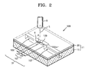
- FIG. 2 is a perspective view illustrating a valve unit according to an embodiment:
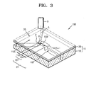
- FIG. 3 is a perspective view illustrating a valve unit according to another embodiment
- FIGS. 4A and 4B are cross-sectional views sequentially illustrating a process of operating the valve unit of FIG. 2 , according to an embodiment:
- FIGS. 5A, 5B , 5C and 5D are cross-sectional views sequentially illustrating a method of fabricating the valve unit of FIG. 2 , according to an embodiment.
- valve unit a valve unit, a microfluidic device including the same, and a method of fabricating the valve unit will be described more fully with reference to the accompanying drawings.
- FIG. 1 is a perspective view illustrating a microfluidic device 10 according to an embodiment.
- the microfluidic device 10 includes a platform 11 that is disk-shaped and rotatable.
- the platform 11 includes a lower substrate 15 and an upper substrate 20 bonded to the lower substrate 15.
- Each of the lower substrate 15 and the upper substrate 20 may be formed of a thermoplastic resin.
- the microfluidic device 10 includes a plurality of chambers 35 for accommodating a fluid therein, a channel 31 that is connected to the chambers 35 and provides a path for fluid flow, and valve units 100 and 50 for controlling the fluid flow via the channel 31.
- the microfluidic device 10 may engage with a spindle motor (not shown) which can rotate the platform 11 at high speed.
- An installation hole 39 is formed at a center portion of the microfluidic device 10 so as to accommodate the spindle motor. Due to rotation of the platform 11 by the spindle motor, fluid in the chambers 35 or channel 31 of the microfluidic device 10 is pressurized in a radial direction towards an outer circumferential portion of the platform 11.
- the arrangement of the chambers 35, the channel 31, and the valve units 100 and 150 is determined by specific biochemical applications, such as centrifugal separation of a fluid sample, an immune serum reaction, gene analysis, or the like. That is, the embodiments are not limited to the arrangement of the chambers 35, the channel 31 and valve units 100 and 150 of the microfluidic device 10 as illustrated in FIG. 1 , and the microfluidic device 10 can have a variety of structures according to the use thereof.
- FIG.2 is a perspective view illustrating one of the valve units 100 of the microfluidic device 10 of FIG. 1 , according to an embodiment.
- FIG.3 is a perspective view illustrating one of the valve units 150 of the microfluidic device 10 of FIG. 1 , according to another embodiment.
- the valve units 100 may be disposed in the channel 31 of the microfluidic device 10 of FIG. 1 .
- the valve units 150 may be disposed adjacent to the chambers 35 or the microfluidic device 10 of FIG. 1 , respectively.
- the valve unit 100 includes a first region 101, a second region 107, and a third region 105 that are formed in the channel 31.
- the first region 101 is formed downward from a top surface of the lower substrate 15
- the second region 107 is formed downward from a top surface of the lower substrate 15, is deeper than the first region 101 and is adjacent to one side of the first region 101 with a step.
- the third region 105 is formed downward from a top surface of the lower substrate 15, is deeper than the first region 101 and is adjacent to the other side of the first region 101 with a step.
- the second region 107 and the third region 105 have the same depth D2, and the first region 101 has a depth D1 which is less than the depth D2 of the second region 107 and the third region 105.
- the first region 101 is a stepped region which protrudes upward from a bottom surface of the channel 31.
- the valve unit 100 includes a valve material chamber or cavity 109 that is formed upward from a bottom surface of the upper substrate 20 and extends only partially through the upper substrate 20.
- the valve material chamber 109 partially overlaps with the first region 101.
- a portion of the first region 101 overlapped with the valve material chamber 109 is referred to as an overlapped portion 102.
- the remaining portion of the first region 101, which is not overlapped with the valve material chamber 109 is referred to as a non-overlapped portion 103.
- a valve material V is initially accommodated in the valve material chamber 109 in a cured form.
- the valve material V accommodated in the valve material chamber 109 is melted so that it flows into the non-overlapped portion 103 of the first region 101.
- the valve material V is then cured again to close the first region 101.
- the non-overlapped portion 103 is adjacent to the third region 105 and the overlapped portion 102 is adjacent to the second region 107.
- the valve material V includes a phase transition material that melts when heated, and a plurality or micro heating particles P (refer to FIG. 4A ) that are dispersed in the phase transition material and generate heat by absorbing electromagnetic wave energy.
- the phase transition material may be a wax. When the wax is heated, it is melted into a liquid state and a volume of the wax expands. Examples of the wax may include paraffin wax, microcrystalline wax, synthetic wax, natural wax, and the like.
- the phase transition material may be a gel or a thermoplastic resin.
- the gel may be one selected from the group consisting of polyacrylamide, polyacrylates, polymethacrylates, and polyvinylamides.
- the thermoplastic resin may be one selected from the group consisting of cyclic olefin copolymer (COC), polymethylmethacrylate (PMMA), polycarbonate (PC), polystyrene (PS), polyoxymethylene (POM), perfluoralkoxy (PFA), polyvinylchloride (PVC), polypropylene (PP), polyethylene terephthalate (PET), polyetheretherketone (PEEK), polyamide (PA), polysulfone (PSU), and polyvinylidene fluoride (PVDF).
- COC cyclic olefin copolymer
- PMMA polymethylmethacrylate
- PC polycarbonate
- PS polystyrene
- POM polyoxymethylene
- PFA perfluoralkoxy
- the micro heating particles P may be uniformly dispersed throughout the wax and may have a diameter of 1 nm to 100 ⁇ m in order to freely pass through the channel 31.
- electromagnetic wave energy is supplied, for example, by radiation of a laser L emitted from a laser light source 5
- the temperature of the micro heating particles P is rapidly increased by the energy such that the micro heating particles P generate heat.
- Each of the micro heating particles P can include a core comprising a metal component and a hydrophobic surface on the core.
- each of the micro heating particles P can have a molecular structure including a iron (Fe) core and a plurality of surfactants coupled to the Fe core and surrounding the Fe core.
- the micro heating particles P may be stored by dispersing them in carrier oil.
- the carrier oil may be hydrophobic so as to allow the micro heating particles P with the hydrophobic surface to be dispersed uniformly.
- the valve material V may be formed by adding carrier oil in which the micro heating particles P are dispersed to a melted phase transition material and mixing them together.
- the micro heating particles P have a polymer type particle structure.
- the embodiments are not limited thereto, and the micro heating particles P can have various other particle structures, such as a quantum dot or a magnetic bead structure.
- the micro heating particles P can include a metal oxide, such as Al 2 O 3 , TiO 2 , Ta 2 O 3 , Fe 2 O 3 , Fe 3 O 4 , or HfO 2 .
- the valve material V may not necessarily include the micro heating particles P, and may include only the phase transition material without the micro heating particles P.
- the valve unit 100 is a normally closed valve in which the channel 31, which is closed, is opened by irradiating electromagnetic wave energy to the valve material V.
- the laser light source 5 is an example of an energy source for irradiating electromagnetic waves to the valve material V. and provides energy to the valve material V by irradiating electromagnetic waves, for example, radiation of the laser L to the valve material V.
- the laser light source 5 may include a laser diode (LD).
- FIGS. 4A and 4B are cross-sectional views sequentially illustrating a process of operating the valve unit 100 of FIG. 2 , according to an embodiment.
- a fluid F is intended to flow from the third region 105 to the second region 107 via the channel 31.
- the valve material V cured in the non-overlapped portion 103 closes the first region 101, and thus the fluid F cannot flow.
- the laser L is irradiated to the valve material V by using the laser light source 5 for a period of time
- the micro heating particles P included in the valve material V are rapidly heated, and thus the phase transition material is rapidly heated.
- the valve material V is rapidly melted, and accordingly, the first region 101 is opened, and the fluid F can flow from the third region 105 to the second region 107. as illustrated in FIG. 4B .
- the valve unit 150 includes a first region 151, a second region 157 and a third region 155.
- the first region 151 and the second region 157 are formed in the channel 31, while the third region 155 is formed in the chamber 35.
- the first region 151 is formed downward from a top surface of the lower substrate 15.
- the second region 157 is formed downward from a top surface or the lower substrate 15, is deeper than the first region 151 and is adjacent to one side of the first region 151 with a step.
- the third region 155 is formed downward from a top surface of the lower substrate 15, is deeper than the first region 151 and is adjacent to the other side of the first region 151 with a step.
- the valve unit 150 includes a valve material chamber 159 that is formed upward from a bottom surface of the upper substrate 20.
- the valve material chamber 159 also overlaps with an overlapped portion 152 of the first region 151 and does not overlap with a non-overlapped portion 153 of the first region 151. similar to the valve material chamber 109 of the valve unit 100 of FIG. 2 .
- the non-overlapped portion 153 is adjacent to the third region 155 and the overlapped portion 152 is adjacent to the second region 157.
- a valve material V is initially accommodated in the valve material chamber 159 in a cured form.
- the valve material V accommodated in the valve material chamber 159 is melted so that it flows into the non-overlapped portion 153 of the first region 151.
- the valve material V is then cured again to close the first region 151.
- the valve unit 150 is also a normally closed valve that opens the channel 31 when the valve material V is irradiated by the laser light L emitted from the laser light source 5, similar to the valve unit 100 of FIG. 2 .
- the valve material V of FIG. 3 is the same as the valve material V of the valve unit 100 of FIG. 2 . and thus a description thereof is not repeated here.
- FIGS. 5A through 5D are cross-sectional views sequentially illustrating a method of fabricating the valve unit of FIG. 2 , according to an embodiment.
- the lower substrate 15 is prepared.
- the lower substrate 15 includes the channel 31 having the first region 101 formed to a first depth D1, the second region 107 formed to a second depth D2 greater than the first depth D1 and adjacent to one side of the first region 101 with a step, and the third region 105 formed to the second depth D2 and adjacent to the other side of the first region 101 with a step.
- the lower substrate 15 may be prepared by injection molding a thermoplastic resin.
- the upper substrate 20 is prepared.
- the upper substrate 20 may be thinner than the lower substrate 15, and includes the valve material chamber 109.
- the upper substrate 20 may also be prepared by injection molding the thermoplastic resin.
- the upper substrate 20 does not include an inlet for injecting the valve material to the microfluidic device 10, and thus a so-called weld line is not formed in the injection molding process.
- a possibility of a rigidity defect of the upper substrate 20 decreases.
- a process of closing the inlet is unnecessary, and thus the manufacturing costs can be reduced.
- a melted valve material V is injected into the valve material chamber 109 by using a means, for example, a dispenser 3, and then cured.
- the valve material V is prepared by mixing a phase transition material with a plurality of micro heating particles P, as described above, and when the valve material V is cured, it is adhered to the valve material chamber 109.
- the surface or the upper substrate 20 in which the valve material chamber 109 is formed is bonded to a surface of the lower substrate 15 in which the first, second and third regions 101, 107 and 105 arc formed, the upper substrate 20 and the lower substrate 15 are bonded to each other using, for example, an ultraviolet (UV) adhesive method or an ultrasonic welding method.
- the upper and lower substrates 20 and 15 are bonded to each other such that the valve material chamber 109 is disposed to partially overlap with a portion of the first region 101.
- the non-overlapped portion 103 of the first region 101 which is not overlapped with the valve material chamber 109, is disposed to be adjacent to the third region 105 and the overlapped portion 102 of the first region 101, which is overlapped with the valve material chamber 109, is disposed to be adjacent to the second region 107.
- valve material V is supplied with energy E by irradiating laser beams thereto, thereby melting the valve material V.
- some or the melted valve material V flows into the non-overlapped portion 103 of the first region 101 by a capillary phenomenon and remains there, the valve material V in the non-overlapped portion 103 is cured again at room temperature, thereby closing the non-overlapped portion 103 of the first region 101.
- the manufacture of the valve unit 100 or FIG. 2 is completed.
- valve material V Since it is difficult to accurately measure the valve material V, a small amount of the valve material V may flow over a boundary of the valve material chamber 109 when the valve material V is injected to the valve material chamber 109. Due to the overflow of the valve material V, when the upper substrate 20 is bonded to the lower substrate 15, portions of the upper substrate 20 and the lower substrate 1 adjacent to the valve material chamber 109 may not be rigidly attached to each other. However, the non-overlapped portion 103 closed by the valve material V is formed upstream to the valve material chamber 109 in terms of the flow direction of the fluid F illustrated in FIG. 4A . and thus the leakage of the fluid F can be prevented. Indeed, through an experiment in which a plurality of valve units the same as the valve unit 100 of FIG. 2 were formed in a platform and the platform was rotated at 4000 rpm for 5 minutes, no leakage of fluid in any of the valve units occurred.
Abstract
Description
- One or more embodiments relate to microfluidics, and more particularly, to a method of fabricating a valve unit.
- In general, microfluidic devices are used to perform biological or chemical reactions by manipulating small amounts of fluid. Microfluidic devices include microfluidic structures arranged in a platform in various forms, such as chips, disks, or the like. Such a microfluidic structure includes a chamber that can accommodate a fluid, a channel through which the fluid can flow, and a valve that can control the flow of the fluid. The chamber, channel, and valve may be disposed in the platform in a variety of configurations.
- A biochip is such a microfluidic structure that is arranged in a small-sized chip platform in order to perform tests including biochemical reactions. In particular, a device that is manufactured to perform multi-step processing and manipulation on a single chip, is referred to as a lab-on-a chip.
- To transfer a fluid in a microfluidic structure, an operating pressure is needed. A capillary pressure or a pressure applied by a separate pump is used as the operating pressure. Recently, centrifugal force-based microfluidic devices in which a microfluidic structure is arranged in a compact disk (CD)-shaped platform have been proposed. These devices are also referred to as Lab CD or Lab-on a CD.
- An example of a valve unit included in a microfluidic device is disclosed in
U.S. Patent Application Publication No. 2008/0042096 . The valve unit includes an injection hole for injecting a phase transition material into the microfluidic device. To form the injection hole in the microfluidic device, which is an injection product, a protrusion corresponding to the injection hole has to be formed in a mold. A resin injected into the mold is separated from each other by the protrusion and then rejoined, which can cause a so-called weld-line formed in the injection product after the resin is cured. The weld-line deteriorates the rigidity of the microfluidic device, resulting in defects. In addition, it is difficult to smoothly polish the mold due to the protrusion formed in the mold. Thus, a surface of the injection product becomes rough and the smoothness thereof deteriorates. In addition, a process of closing the injection hole is further needed after forming the valve unit, and thus the manufacturing costs increase. Moreover, due to a draft angle formed in the protrusion in order to easily separate the injection product from the mold, an inclination is formed in an inner circumferential surface of the injection hole. As a result, the injection product has a step difference such that when the valve is operated by applying energy, such as electromagnetic waves, the step difference of the injection hole may cause diffusion of light. Thus, an operation of the valve unit may be interfered with and malfunction. - Other examples of a valve unit included in a microfluidic device are disclosed in european patent application publication No.
EP 1 889 661 A1 . - One or more embodiments provide a method of fabricating a valve unit which unit does not include an inlet for injecting a valve material to an inside of a microfluidic device, and thus can be manufactured relatively inexpensively.
- According to an aspect of one or more embodiments, there is provided a method of fabricating a valve unit, with the features of claim 1.
- Each of a lower substrate and an upper substrate may comprise a thermoplastic resin.
- The valve material may comprise a phase transition material that is in a solid state at room temperature and melted when the phase transition material absorbs energy.
- The valve material may comprise a plurality or micro heating particles, dispersed in the phase transition material, generating heat when the micro heating particles absorb electromagnetic wave energy.
- The micro heating particles may comprise metal oxide particles.
- The phase transition material may comprise a wax, a gel, or a thermoplastic resin.
- The above and other aspects will become more apparent by describing in detail exemplary embodiments thereof with reference to the attached drawings in which:
-
FIG. 1 is a perspective view illustrating a microfluidic device according to an embodiment; -
FIG. 2 is a perspective view illustrating a valve unit according to an embodiment: -
FIG. 3 is a perspective view illustrating a valve unit according to another embodiment; -
FIGS. 4A and 4B are cross-sectional views sequentially illustrating a process of operating the valve unit ofFIG. 2 , according to an embodiment: and -
FIGS. 5A, 5B ,5C and 5D are cross-sectional views sequentially illustrating a method of fabricating the valve unit ofFIG. 2 , according to an embodiment. - Hereinafter, exemplary embodiments of a valve unit, a microfluidic device including the same, and a method of fabricating the valve unit will be described more fully with reference to the accompanying drawings.
-
FIG. 1 is a perspective view illustrating amicrofluidic device 10 according to an embodiment. Referring toFIG. 1 , themicrofluidic device 10 includes aplatform 11 that is disk-shaped and rotatable. Theplatform 11 includes alower substrate 15 and anupper substrate 20 bonded to thelower substrate 15. Each of thelower substrate 15 and theupper substrate 20 may be formed of a thermoplastic resin. - The
microfluidic device 10 includes a plurality ofchambers 35 for accommodating a fluid therein, achannel 31 that is connected to thechambers 35 and provides a path for fluid flow, andvalve units 100 and 50 for controlling the fluid flow via thechannel 31. In addition, themicrofluidic device 10 may engage with a spindle motor (not shown) which can rotate theplatform 11 at high speed. Aninstallation hole 39 is formed at a center portion of themicrofluidic device 10 so as to accommodate the spindle motor. Due to rotation of theplatform 11 by the spindle motor, fluid in thechambers 35 orchannel 31 of themicrofluidic device 10 is pressurized in a radial direction towards an outer circumferential portion of theplatform 11. - In the
microfluidic device 10. the arrangement of thechambers 35, thechannel 31, and thevalve units chambers 35, thechannel 31 andvalve units microfluidic device 10 as illustrated inFIG. 1 , and themicrofluidic device 10 can have a variety of structures according to the use thereof. -
FIG.2 is a perspective view illustrating one of thevalve units 100 of themicrofluidic device 10 ofFIG. 1 , according to an embodiment.FIG.3 is a perspective view illustrating one of thevalve units 150 of themicrofluidic device 10 ofFIG. 1 , according to another embodiment. Thevalve units 100 may be disposed in thechannel 31 of themicrofluidic device 10 ofFIG. 1 . Thevalve units 150 may be disposed adjacent to thechambers 35 or themicrofluidic device 10 ofFIG. 1 , respectively. - Referring to
FIG. 2 , thevalve unit 100 includes afirst region 101, asecond region 107, and athird region 105 that are formed in thechannel 31. Thefirst region 101 is formed downward from a top surface of thelower substrate 15, thesecond region 107 is formed downward from a top surface of thelower substrate 15, is deeper than thefirst region 101 and is adjacent to one side of thefirst region 101 with a step. Thethird region 105 is formed downward from a top surface of thelower substrate 15, is deeper than thefirst region 101 and is adjacent to the other side of thefirst region 101 with a step. Referring toFIG. 4A , thesecond region 107 and thethird region 105 have the same depth D2, and thefirst region 101 has a depth D1 which is less than the depth D2 of thesecond region 107 and thethird region 105. Thus, thefirst region 101 is a stepped region which protrudes upward from a bottom surface of thechannel 31. - In addition, the
valve unit 100 includes a valve material chamber orcavity 109 that is formed upward from a bottom surface of theupper substrate 20 and extends only partially through theupper substrate 20. Thevalve material chamber 109 partially overlaps with thefirst region 101. A portion of thefirst region 101 overlapped with thevalve material chamber 109 is referred to as an overlappedportion 102. and the remaining portion of thefirst region 101, which is not overlapped with thevalve material chamber 109, is referred to as anon-overlapped portion 103. A valve material V is initially accommodated in thevalve material chamber 109 in a cured form. The valve material V accommodated in thevalve material chamber 109 is melted so that it flows into thenon-overlapped portion 103 of thefirst region 101. The valve material V is then cured again to close thefirst region 101. Thenon-overlapped portion 103 is adjacent to thethird region 105 and the overlappedportion 102 is adjacent to thesecond region 107. - The valve material V includes a phase transition material that melts when heated, and a plurality or micro heating particles P (refer to
FIG. 4A ) that are dispersed in the phase transition material and generate heat by absorbing electromagnetic wave energy. For example, the phase transition material may be a wax. When the wax is heated, it is melted into a liquid state and a volume of the wax expands. Examples of the wax may include paraffin wax, microcrystalline wax, synthetic wax, natural wax, and the like. - Alternatively, the phase transition material may be a gel or a thermoplastic resin. The gel may be one selected from the group consisting of polyacrylamide, polyacrylates, polymethacrylates, and polyvinylamides. The thermoplastic resin may be one selected from the group consisting of cyclic olefin copolymer (COC), polymethylmethacrylate (PMMA), polycarbonate (PC), polystyrene (PS), polyoxymethylene (POM), perfluoralkoxy (PFA), polyvinylchloride (PVC), polypropylene (PP), polyethylene terephthalate (PET), polyetheretherketone (PEEK), polyamide (PA), polysulfone (PSU), and polyvinylidene fluoride (PVDF).
- The micro heating particles P may be uniformly dispersed throughout the wax and may have a diameter of 1 nm to 100 µm in order to freely pass through the
channel 31. When electromagnetic wave energy is supplied, for example, by radiation of a laser L emitted from alaser light source 5, the temperature of the micro heating particles P is rapidly increased by the energy such that the micro heating particles P generate heat. Each of the micro heating particles P can include a core comprising a metal component and a hydrophobic surface on the core. For example, each of the micro heating particles P can have a molecular structure including a iron (Fe) core and a plurality of surfactants coupled to the Fe core and surrounding the Fe core. - In general, the micro heating particles P may be stored by dispersing them in carrier oil. The carrier oil may be hydrophobic so as to allow the micro heating particles P with the hydrophobic surface to be dispersed uniformly. The valve material V may be formed by adding carrier oil in which the micro heating particles P are dispersed to a melted phase transition material and mixing them together.
- In the above description, the micro heating particles P have a polymer type particle structure. However, the embodiments are not limited thereto, and the micro heating particles P can have various other particle structures, such as a quantum dot or a magnetic bead structure. Further, the micro heating particles P can include a metal oxide, such as Al2O3, TiO2, Ta2O3, Fe2O3, Fe3O4, or HfO2. Alternatively, the valve material V may not necessarily include the micro heating particles P, and may include only the phase transition material without the micro heating particles P.
- The
valve unit 100 is a normally closed valve in which thechannel 31, which is closed, is opened by irradiating electromagnetic wave energy to the valve material V. Thelaser light source 5 is an example of an energy source for irradiating electromagnetic waves to the valve material V. and provides energy to the valve material V by irradiating electromagnetic waves, for example, radiation of the laser L to the valve material V. Thelaser light source 5 may include a laser diode (LD). -
FIGS. 4A and 4B are cross-sectional views sequentially illustrating a process of operating thevalve unit 100 ofFIG. 2 , according to an embodiment. Referring toFIG. 4A , a fluid F is intended to flow from thethird region 105 to thesecond region 107 via thechannel 31. However, the valve material V cured in thenon-overlapped portion 103 closes thefirst region 101, and thus the fluid F cannot flow. In this regard, when the laser L is irradiated to the valve material V by using thelaser light source 5 for a period of time, the micro heating particles P included in the valve material V are rapidly heated, and thus the phase transition material is rapidly heated. As a result, the valve material V is rapidly melted, and accordingly, thefirst region 101 is opened, and the fluid F can flow from thethird region 105 to thesecond region 107. as illustrated inFIG. 4B . - Referring to
FIG. 3 , thevalve unit 150 includes afirst region 151, asecond region 157 and athird region 155. Thefirst region 151 and thesecond region 157 are formed in thechannel 31, while thethird region 155 is formed in thechamber 35. Thefirst region 151 is formed downward from a top surface of thelower substrate 15. Thesecond region 157 is formed downward from a top surface or thelower substrate 15, is deeper than thefirst region 151 and is adjacent to one side of thefirst region 151 with a step. Thethird region 155 is formed downward from a top surface of thelower substrate 15, is deeper than thefirst region 151 and is adjacent to the other side of thefirst region 151 with a step. - In addition, the
valve unit 150 includes avalve material chamber 159 that is formed upward from a bottom surface of theupper substrate 20. Thevalve material chamber 159 also overlaps with an overlappedportion 152 of thefirst region 151 and does not overlap with anon-overlapped portion 153 of thefirst region 151. similar to thevalve material chamber 109 of thevalve unit 100 ofFIG. 2 . Thenon-overlapped portion 153 is adjacent to thethird region 155 and the overlappedportion 152 is adjacent to thesecond region 157. A valve material V is initially accommodated in thevalve material chamber 159 in a cured form. The valve material V accommodated in thevalve material chamber 159 is melted so that it flows into thenon-overlapped portion 153 of thefirst region 151. The valve material V is then cured again to close thefirst region 151. - The
valve unit 150 is also a normally closed valve that opens thechannel 31 when the valve material V is irradiated by the laser light L emitted from thelaser light source 5, similar to thevalve unit 100 ofFIG. 2 . The valve material V ofFIG. 3 is the same as the valve material V of thevalve unit 100 ofFIG. 2 . and thus a description thereof is not repeated here. -
FIGS. 5A through 5D are cross-sectional views sequentially illustrating a method of fabricating the valve unit ofFIG. 2 , according to an embodiment. - Referring to
FIG. 5A , to fabricate thevalve unit 100 ofFIG. 2 , first, thelower substrate 15 is prepared. Thelower substrate 15 includes thechannel 31 having thefirst region 101 formed to a first depth D1, thesecond region 107 formed to a second depth D2 greater than the first depth D1 and adjacent to one side of thefirst region 101 with a step, and thethird region 105 formed to the second depth D2 and adjacent to the other side of thefirst region 101 with a step. Thelower substrate 15 may be prepared by injection molding a thermoplastic resin. - Referring to
FIG. 5B , to fabricate thevalve unit 100, theupper substrate 20 is prepared. Theupper substrate 20 may be thinner than thelower substrate 15, and includes thevalve material chamber 109. Theupper substrate 20 may also be prepared by injection molding the thermoplastic resin. Theupper substrate 20 does not include an inlet for injecting the valve material to themicrofluidic device 10, and thus a so-called weld line is not formed in the injection molding process. Thus, a possibility of a rigidity defect of theupper substrate 20 decreases. In addition, a process of closing the inlet is unnecessary, and thus the manufacturing costs can be reduced. - A melted valve material V is injected into the
valve material chamber 109 by using a means, for example, adispenser 3, and then cured. The valve material V is prepared by mixing a phase transition material with a plurality of micro heating particles P, as described above, and when the valve material V is cured, it is adhered to thevalve material chamber 109. - Referring to
FIG. 5C , the surface or theupper substrate 20 in which thevalve material chamber 109 is formed is bonded to a surface of thelower substrate 15 in which the first, second andthird regions upper substrate 20 and thelower substrate 15 are bonded to each other using, for example, an ultraviolet (UV) adhesive method or an ultrasonic welding method. The upper andlower substrates valve material chamber 109 is disposed to partially overlap with a portion of thefirst region 101. In addition, thenon-overlapped portion 103 of thefirst region 101, which is not overlapped with thevalve material chamber 109, is disposed to be adjacent to thethird region 105 and the overlappedportion 102 of thefirst region 101, which is overlapped with thevalve material chamber 109, is disposed to be adjacent to thesecond region 107. - Then, the
lower substrate 15 and theupper substrate 20 are heated, or the valve material V is supplied with energy E by irradiating laser beams thereto, thereby melting the valve material V. Referring toFIG. 5D , some or the melted valve material V flows into thenon-overlapped portion 103 of thefirst region 101 by a capillary phenomenon and remains there, the valve material V in thenon-overlapped portion 103 is cured again at room temperature, thereby closing thenon-overlapped portion 103 of thefirst region 101. As a result, the manufacture of thevalve unit 100 orFIG. 2 is completed. - Since it is difficult to accurately measure the valve material V, a small amount of the valve material V may flow over a boundary of the
valve material chamber 109 when the valve material V is injected to thevalve material chamber 109. Due to the overflow of the valve material V, when theupper substrate 20 is bonded to thelower substrate 15, portions of theupper substrate 20 and the lower substrate 1 adjacent to thevalve material chamber 109 may not be rigidly attached to each other. However, thenon-overlapped portion 103 closed by the valve material V is formed upstream to thevalve material chamber 109 in terms of the flow direction of the fluid F illustrated inFIG. 4A . and thus the leakage of the fluid F can be prevented. Indeed, through an experiment in which a plurality of valve units the same as thevalve unit 100 ofFIG. 2 were formed in a platform and the platform was rotated at 4000 rpm for 5 minutes, no leakage of fluid in any of the valve units occurred. - While exemplary embodiments has been particularly shown and described, it will be understood by those of ordinary skill in the art that various changes in form and details may be made therein without departing from the scope of the inventive concept as defined by the following claims.
Claims (6)
- A method of fabricating a valve unit (100), the method comprising:preparing a lower substrate (15) comprising a channel (31) including a first region (101, 151) and a second region (107, 157) which is deeper than the first region and is adjacent to one side of the first region;preparing an upper substrate (20) comprising a valve material chamber (109, 159) which extends only partially through the upper substrate;filling the valve material chamber (109, 159) with a valve material (V) and curing the valve material in the valve material chamber;attaching a surface of the upper substrate (20) in which the valve material chamber (109, 159) is formed to a surface of the lower substrate (15) in which the channel (31) is formed, so that the valve material chamber (109, 159) overlaps the first region in an overlapped portion (102, 152), and does not overlap the first region in a non-overlapped portion (103, 153);melting the valve material (V) accommodated in the valve material chamber to flow the valve material into the non-overlapped portion (103, 153) of the first region (101, 151); andcuring the valve material flowed into the non-overlapped portion to close the first region (101, 151).
- The method of claim 1, wherein the channel (31) of the lower substrate (15) further includes a third region (105) which is deeper than the first region and is adjacent to another side of the first region and wherein the attaching the upper substrate (20) to the lower substrate (15) comprises attaching the upper and lower substrates so that the non-overlapped portion (103) of the first region (101) is adjacent to the third region (105) and the overlapped portion (102) of the first region is adjacent to the second region (107).
- The method of claim 1, wherein lower substrate (15) further comprises a chamber (35) including a third region (155) which is deeper than the first region (151) and is adjacent to another side of the first region and wherein the attaching the upper substrate (20) to the lower substrate (15) comprises attaching the upper and lower substrates so that the non-overlapped portion (153) of the first region (151) is adjacent to the third region (155) and the overlapped portion (152) of the first region is adjacent to the second region (157).
- The method of claim 1, wherein the valve material (V) comprises a phase transition material that is in a solid state at room temperature and melts when heated.
- The method of claim 4, wherein the valve material further comprises a plurality of micro heating particles (P) which are dispersed in the phase transition material and generate heat when subjected electromagnetic energy.
- The method of claim 1, wherein the attaching the upper substrate (20) to the lower substrate (15) comprises attaching the upper and lower substrates so that the valve material chamber (109, 159) overlaps a portion of the second region (107, 157).
Applications Claiming Priority (1)
| Application Number | Priority Date | Filing Date | Title |
|---|---|---|---|
| KR1020080044728A KR100955481B1 (en) | 2008-05-14 | 2008-05-14 | Valve unit, microfluidic device with the same, and method for fabricating the valve unit |
Publications (2)
| Publication Number | Publication Date |
|---|---|
| EP2119505A1 EP2119505A1 (en) | 2009-11-18 |
| EP2119505B1 true EP2119505B1 (en) | 2011-12-21 |
Family
ID=40874736
Family Applications (1)
| Application Number | Title | Priority Date | Filing Date |
|---|---|---|---|
| EP09160093A Active EP2119505B1 (en) | 2008-05-14 | 2009-05-13 | Method of fabricating a valve unit |
Country Status (5)
| Country | Link |
|---|---|
| US (1) | US8429821B2 (en) |
| EP (1) | EP2119505B1 (en) |
| JP (1) | JP2009274067A (en) |
| KR (1) | KR100955481B1 (en) |
| AT (1) | ATE537900T1 (en) |
Families Citing this family (3)
| Publication number | Priority date | Publication date | Assignee | Title |
|---|---|---|---|---|
| US8779533B2 (en) | 2011-07-12 | 2014-07-15 | Robert Bosch Gmbh | MEMS with single use valve and method of operation |
| KR102176587B1 (en) | 2013-10-15 | 2020-11-10 | 삼성전자주식회사 | Sample analysis method, and dynamic valve operating method |
| USD841186S1 (en) * | 2015-12-23 | 2019-02-19 | Tunghai University | Biochip |
Family Cites Families (6)
| Publication number | Priority date | Publication date | Assignee | Title |
|---|---|---|---|---|
| JP3469585B2 (en) | 1997-05-23 | 2003-11-25 | ガメラ バイオサイエンス コーポレイション | Apparatus and method for using centripetal acceleration to drive flow motion in microfluidics systems |
| KR100738113B1 (en) | 2006-05-10 | 2007-07-12 | 삼성전자주식회사 | Phase transition type valve and the manufacturing method thereof |
| EP1884284A1 (en) | 2006-08-04 | 2008-02-06 | Samsung Electronics Co., Ltd. | Closing valve unit and reaction apparatus having closing valve |
| KR100763924B1 (en) | 2006-08-16 | 2007-10-05 | 삼성전자주식회사 | Valve unit, reaction apparatus with the same, and valve forming method in channel |
| US8464760B2 (en) | 2006-08-16 | 2013-06-18 | Samsung Electronic Co., Ltd. | Valve unit, reaction apparatus with the same, and method of forming valve in channel |
| KR101258434B1 (en) * | 2007-05-03 | 2013-05-02 | 삼성전자주식회사 | Microfluidic system and fabricating method of the same |
-
2008
- 2008-05-14 KR KR1020080044728A patent/KR100955481B1/en active IP Right Grant
-
2009
- 2009-05-13 AT AT09160093T patent/ATE537900T1/en active
- 2009-05-13 EP EP09160093A patent/EP2119505B1/en active Active
- 2009-05-13 US US12/464,938 patent/US8429821B2/en active Active
- 2009-05-13 JP JP2009116981A patent/JP2009274067A/en active Pending
Also Published As
| Publication number | Publication date |
|---|---|
| KR20090118753A (en) | 2009-11-18 |
| ATE537900T1 (en) | 2012-01-15 |
| JP2009274067A (en) | 2009-11-26 |
| EP2119505A1 (en) | 2009-11-18 |
| KR100955481B1 (en) | 2010-04-30 |
| US20090282681A1 (en) | 2009-11-19 |
| US8429821B2 (en) | 2013-04-30 |
Similar Documents
| Publication | Publication Date | Title |
|---|---|---|
| KR101258434B1 (en) | Microfluidic system and fabricating method of the same | |
| JP5600180B2 (en) | Valve unit, microfluidic device provided with the same, and driving method of valve unit | |
| US7951332B2 (en) | Centrifugal force based microfluidic device for dilution and microfluidic system including the same | |
| US8119079B2 (en) | Microfluidic apparatus having fluid container | |
| US8048387B2 (en) | Centrifugal microfluidic device having sample distribution structure and centrifugal microfluidic system including the centrifugal microfluidic device | |
| US9011795B2 (en) | Valve unit, microfluidic device with the valve unit, and microfluidic substrate | |
| US8235073B2 (en) | Microfluidic valve unit for controlling flow of fluid and method of fabricating the same | |
| US8105551B2 (en) | Microfluidic device and method of fabricating the same | |
| JP5171153B2 (en) | Valve unit, reaction apparatus equipped with the same, and method for forming a valve in a channel | |
| KR20130029277A (en) | Microfluidic device and control method thereof | |
| EP2119505B1 (en) | Method of fabricating a valve unit | |
| KR101391736B1 (en) | Microfluidic valve, manufacturing process of the microfluidic valve and microfluidic device comprising the microfluidic valve | |
| KR101473871B1 (en) | Fabricating method of valve unit for controlling microfluid, valve unit for controlling microfluid, and microfluidic device with the valve unit |
Legal Events
| Date | Code | Title | Description |
|---|---|---|---|
| PUAI | Public reference made under article 153(3) epc to a published international application that has entered the european phase |
Free format text: ORIGINAL CODE: 0009012 |
|
| AK | Designated contracting states |
Kind code of ref document: A1 Designated state(s): AT BE BG CH CY CZ DE DK EE ES FI FR GB GR HR HU IE IS IT LI LT LU LV MC MK MT NL NO PL PT RO SE SI SK TR |
|
| 17P | Request for examination filed |
Effective date: 20100416 |
|
| 17Q | First examination report despatched |
Effective date: 20100920 |
|
| REG | Reference to a national code |
Ref country code: DE Ref legal event code: R079 Ref document number: 602009004266 Country of ref document: DE Free format text: PREVIOUS MAIN CLASS: B01L0003020000 Ipc: B01L0003000000 |
|
| GRAP | Despatch of communication of intention to grant a patent |
Free format text: ORIGINAL CODE: EPIDOSNIGR1 |
|
| RTI1 | Title (correction) |
Free format text: METHOD OF FABRICATING A VALVE UNIT |
|
| RIC1 | Information provided on ipc code assigned before grant |
Ipc: B01L 3/00 20060101AFI20110615BHEP Ipc: F16K 99/00 20060101ALI20110615BHEP |
|
| RIN1 | Information on inventor provided before grant (corrected) |
Inventor name: LEE, JEONG-GUN Inventor name: PARK, JONG-MYEON Inventor name: CHUNG, JONG-SUK |
|
| GRAS | Grant fee paid |
Free format text: ORIGINAL CODE: EPIDOSNIGR3 |
|
| GRAA | (expected) grant |
Free format text: ORIGINAL CODE: 0009210 |
|
| AK | Designated contracting states |
Kind code of ref document: B1 Designated state(s): AT BE BG CH CY CZ DE DK EE ES FI FR GB GR HR HU IE IS IT LI LT LU LV MC MK MT NL NO PL PT RO SE SI SK TR |
|
| REG | Reference to a national code |
Ref country code: GB Ref legal event code: FG4D |
|
| REG | Reference to a national code |
Ref country code: CH Ref legal event code: EP |
|
| REG | Reference to a national code |
Ref country code: AT Ref legal event code: REF Ref document number: 537900 Country of ref document: AT Kind code of ref document: T Effective date: 20120115 |
|
| REG | Reference to a national code |
Ref country code: IE Ref legal event code: FG4D |
|
| REG | Reference to a national code |
Ref country code: DE Ref legal event code: R096 Ref document number: 602009004266 Country of ref document: DE Effective date: 20120322 |
|
| REG | Reference to a national code |
Ref country code: NL Ref legal event code: T3 |
|
| PG25 | Lapsed in a contracting state [announced via postgrant information from national office to epo] |
Ref country code: NO Free format text: LAPSE BECAUSE OF FAILURE TO SUBMIT A TRANSLATION OF THE DESCRIPTION OR TO PAY THE FEE WITHIN THE PRESCRIBED TIME-LIMIT Effective date: 20120321 Ref country code: LT Free format text: LAPSE BECAUSE OF FAILURE TO SUBMIT A TRANSLATION OF THE DESCRIPTION OR TO PAY THE FEE WITHIN THE PRESCRIBED TIME-LIMIT Effective date: 20111221 |
|
| LTIE | Lt: invalidation of european patent or patent extension |
Effective date: 20111221 |
|
| PG25 | Lapsed in a contracting state [announced via postgrant information from national office to epo] |
Ref country code: SI Free format text: LAPSE BECAUSE OF FAILURE TO SUBMIT A TRANSLATION OF THE DESCRIPTION OR TO PAY THE FEE WITHIN THE PRESCRIBED TIME-LIMIT Effective date: 20111221 Ref country code: GR Free format text: LAPSE BECAUSE OF FAILURE TO SUBMIT A TRANSLATION OF THE DESCRIPTION OR TO PAY THE FEE WITHIN THE PRESCRIBED TIME-LIMIT Effective date: 20120322 Ref country code: SE Free format text: LAPSE BECAUSE OF FAILURE TO SUBMIT A TRANSLATION OF THE DESCRIPTION OR TO PAY THE FEE WITHIN THE PRESCRIBED TIME-LIMIT Effective date: 20111221 Ref country code: HR Free format text: LAPSE BECAUSE OF FAILURE TO SUBMIT A TRANSLATION OF THE DESCRIPTION OR TO PAY THE FEE WITHIN THE PRESCRIBED TIME-LIMIT Effective date: 20111221 Ref country code: LV Free format text: LAPSE BECAUSE OF FAILURE TO SUBMIT A TRANSLATION OF THE DESCRIPTION OR TO PAY THE FEE WITHIN THE PRESCRIBED TIME-LIMIT Effective date: 20111221 |
|
| PG25 | Lapsed in a contracting state [announced via postgrant information from national office to epo] |
Ref country code: CY Free format text: LAPSE BECAUSE OF FAILURE TO SUBMIT A TRANSLATION OF THE DESCRIPTION OR TO PAY THE FEE WITHIN THE PRESCRIBED TIME-LIMIT Effective date: 20111221 Ref country code: BE Free format text: LAPSE BECAUSE OF FAILURE TO SUBMIT A TRANSLATION OF THE DESCRIPTION OR TO PAY THE FEE WITHIN THE PRESCRIBED TIME-LIMIT Effective date: 20111221 |
|
| PG25 | Lapsed in a contracting state [announced via postgrant information from national office to epo] |
Ref country code: BG Free format text: LAPSE BECAUSE OF FAILURE TO SUBMIT A TRANSLATION OF THE DESCRIPTION OR TO PAY THE FEE WITHIN THE PRESCRIBED TIME-LIMIT Effective date: 20120321 Ref country code: IS Free format text: LAPSE BECAUSE OF FAILURE TO SUBMIT A TRANSLATION OF THE DESCRIPTION OR TO PAY THE FEE WITHIN THE PRESCRIBED TIME-LIMIT Effective date: 20120421 Ref country code: SK Free format text: LAPSE BECAUSE OF FAILURE TO SUBMIT A TRANSLATION OF THE DESCRIPTION OR TO PAY THE FEE WITHIN THE PRESCRIBED TIME-LIMIT Effective date: 20111221 Ref country code: CZ Free format text: LAPSE BECAUSE OF FAILURE TO SUBMIT A TRANSLATION OF THE DESCRIPTION OR TO PAY THE FEE WITHIN THE PRESCRIBED TIME-LIMIT Effective date: 20111221 Ref country code: EE Free format text: LAPSE BECAUSE OF FAILURE TO SUBMIT A TRANSLATION OF THE DESCRIPTION OR TO PAY THE FEE WITHIN THE PRESCRIBED TIME-LIMIT Effective date: 20111221 |
|
| PG25 | Lapsed in a contracting state [announced via postgrant information from national office to epo] |
Ref country code: PT Free format text: LAPSE BECAUSE OF FAILURE TO SUBMIT A TRANSLATION OF THE DESCRIPTION OR TO PAY THE FEE WITHIN THE PRESCRIBED TIME-LIMIT Effective date: 20120423 Ref country code: PL Free format text: LAPSE BECAUSE OF FAILURE TO SUBMIT A TRANSLATION OF THE DESCRIPTION OR TO PAY THE FEE WITHIN THE PRESCRIBED TIME-LIMIT Effective date: 20111221 Ref country code: RO Free format text: LAPSE BECAUSE OF FAILURE TO SUBMIT A TRANSLATION OF THE DESCRIPTION OR TO PAY THE FEE WITHIN THE PRESCRIBED TIME-LIMIT Effective date: 20111221 |
|
| REG | Reference to a national code |
Ref country code: AT Ref legal event code: MK05 Ref document number: 537900 Country of ref document: AT Kind code of ref document: T Effective date: 20111221 |
|
| RAP2 | Party data changed (patent owner data changed or rights of a patent transferred) |
Owner name: SAMSUNG ELECTRONICS CO., LTD. |
|
| PLBE | No opposition filed within time limit |
Free format text: ORIGINAL CODE: 0009261 |
|
| STAA | Information on the status of an ep patent application or granted ep patent |
Free format text: STATUS: NO OPPOSITION FILED WITHIN TIME LIMIT |
|
| PG25 | Lapsed in a contracting state [announced via postgrant information from national office to epo] |
Ref country code: DK Free format text: LAPSE BECAUSE OF FAILURE TO SUBMIT A TRANSLATION OF THE DESCRIPTION OR TO PAY THE FEE WITHIN THE PRESCRIBED TIME-LIMIT Effective date: 20111221 |
|
| 26N | No opposition filed |
Effective date: 20120924 |
|
| PG25 | Lapsed in a contracting state [announced via postgrant information from national office to epo] |
Ref country code: MC Free format text: LAPSE BECAUSE OF NON-PAYMENT OF DUE FEES Effective date: 20120531 |
|
| REG | Reference to a national code |
Ref country code: DE Ref legal event code: R097 Ref document number: 602009004266 Country of ref document: DE Effective date: 20120924 |
|
| PG25 | Lapsed in a contracting state [announced via postgrant information from national office to epo] |
Ref country code: AT Free format text: LAPSE BECAUSE OF FAILURE TO SUBMIT A TRANSLATION OF THE DESCRIPTION OR TO PAY THE FEE WITHIN THE PRESCRIBED TIME-LIMIT Effective date: 20111221 |
|
| REG | Reference to a national code |
Ref country code: IE Ref legal event code: MM4A |
|
| PG25 | Lapsed in a contracting state [announced via postgrant information from national office to epo] |
Ref country code: MK Free format text: LAPSE BECAUSE OF FAILURE TO SUBMIT A TRANSLATION OF THE DESCRIPTION OR TO PAY THE FEE WITHIN THE PRESCRIBED TIME-LIMIT Effective date: 20111221 |
|
| PG25 | Lapsed in a contracting state [announced via postgrant information from national office to epo] |
Ref country code: IE Free format text: LAPSE BECAUSE OF NON-PAYMENT OF DUE FEES Effective date: 20120513 Ref country code: ES Free format text: LAPSE BECAUSE OF FAILURE TO SUBMIT A TRANSLATION OF THE DESCRIPTION OR TO PAY THE FEE WITHIN THE PRESCRIBED TIME-LIMIT Effective date: 20120401 |
|
| PG25 | Lapsed in a contracting state [announced via postgrant information from national office to epo] |
Ref country code: FI Free format text: LAPSE BECAUSE OF FAILURE TO SUBMIT A TRANSLATION OF THE DESCRIPTION OR TO PAY THE FEE WITHIN THE PRESCRIBED TIME-LIMIT Effective date: 20111221 |
|
| PG25 | Lapsed in a contracting state [announced via postgrant information from national office to epo] |
Ref country code: MT Free format text: LAPSE BECAUSE OF FAILURE TO SUBMIT A TRANSLATION OF THE DESCRIPTION OR TO PAY THE FEE WITHIN THE PRESCRIBED TIME-LIMIT Effective date: 20111221 |
|
| REG | Reference to a national code |
Ref country code: CH Ref legal event code: PL |
|
| PG25 | Lapsed in a contracting state [announced via postgrant information from national office to epo] |
Ref country code: LI Free format text: LAPSE BECAUSE OF NON-PAYMENT OF DUE FEES Effective date: 20130531 Ref country code: CH Free format text: LAPSE BECAUSE OF NON-PAYMENT OF DUE FEES Effective date: 20130531 |
|
| PG25 | Lapsed in a contracting state [announced via postgrant information from national office to epo] |
Ref country code: TR Free format text: LAPSE BECAUSE OF FAILURE TO SUBMIT A TRANSLATION OF THE DESCRIPTION OR TO PAY THE FEE WITHIN THE PRESCRIBED TIME-LIMIT Effective date: 20111221 |
|
| PG25 | Lapsed in a contracting state [announced via postgrant information from national office to epo] |
Ref country code: LU Free format text: LAPSE BECAUSE OF NON-PAYMENT OF DUE FEES Effective date: 20120513 |
|
| PG25 | Lapsed in a contracting state [announced via postgrant information from national office to epo] |
Ref country code: HU Free format text: LAPSE BECAUSE OF FAILURE TO SUBMIT A TRANSLATION OF THE DESCRIPTION OR TO PAY THE FEE WITHIN THE PRESCRIBED TIME-LIMIT Effective date: 20090513 |
|
| REG | Reference to a national code |
Ref country code: FR Ref legal event code: PLFP Year of fee payment: 8 |
|
| REG | Reference to a national code |
Ref country code: FR Ref legal event code: PLFP Year of fee payment: 9 |
|
| REG | Reference to a national code |
Ref country code: FR Ref legal event code: PLFP Year of fee payment: 10 |
|
| REG | Reference to a national code |
Ref country code: NL Ref legal event code: PD Owner name: PRECISION BIOSENSOR INC.; KR Free format text: DETAILS ASSIGNMENT: CHANGE OF OWNER(S), ASSIGNMENT; FORMER OWNER NAME: SAMSUNG ELECTRONICS CO., LTD. Effective date: 20220819 |
|
| REG | Reference to a national code |
Ref country code: DE Ref legal event code: R081 Ref document number: 602009004266 Country of ref document: DE Owner name: PRECISION BIOSENSOR INC., DAEJEON, KR Free format text: FORMER OWNER: SAMSUNG ELECTRONICS CO., LTD., SUWON-SI, GYEONGGI-DO, KR |
|
| REG | Reference to a national code |
Ref country code: GB Ref legal event code: 732E Free format text: REGISTERED BETWEEN 20220825 AND 20220831 |
|
| PGFP | Annual fee paid to national office [announced via postgrant information from national office to epo] |
Ref country code: NL Payment date: 20230426 Year of fee payment: 15 |
|
| PGFP | Annual fee paid to national office [announced via postgrant information from national office to epo] |
Ref country code: IT Payment date: 20230427 Year of fee payment: 15 Ref country code: FR Payment date: 20230421 Year of fee payment: 15 Ref country code: DE Payment date: 20230425 Year of fee payment: 15 |
|
| PGFP | Annual fee paid to national office [announced via postgrant information from national office to epo] |
Ref country code: GB Payment date: 20230427 Year of fee payment: 15 |