EP2119480A1 - Game machine - Google Patents
Game machine Download PDFInfo
- Publication number
- EP2119480A1 EP2119480A1 EP08710608A EP08710608A EP2119480A1 EP 2119480 A1 EP2119480 A1 EP 2119480A1 EP 08710608 A EP08710608 A EP 08710608A EP 08710608 A EP08710608 A EP 08710608A EP 2119480 A1 EP2119480 A1 EP 2119480A1
- Authority
- EP
- European Patent Office
- Prior art keywords
- game
- ball
- prize winning
- medal
- lottery
- Prior art date
- Legal status (The legal status is an assumption and is not a legal conclusion. Google has not performed a legal analysis and makes no representation as to the accuracy of the status listed.)
- Withdrawn
Links
Images


Classifications
-
- G—PHYSICS
- G07—CHECKING-DEVICES
- G07F—COIN-FREED OR LIKE APPARATUS
- G07F17/00—Coin-freed apparatus for hiring articles; Coin-freed facilities or services
- G07F17/32—Coin-freed apparatus for hiring articles; Coin-freed facilities or services for games, toys, sports, or amusements
- G07F17/3286—Type of games
- G07F17/3297—Fairground games, e.g. Tivoli, coin pusher machines, cranes
Definitions
- the present invention relates to a game machine including game devices for generating a dividend.
- Patent Document 1 Japanese Patent Application Laid-Open No. 2005-224326
- the game attracts the player for a long time because the prize winning is generated little by little, the player is possibly distracted from the game because of sluggish progress of the game.
- a prize winning occurrence interval may be narrowed, the player reaches a dividend amount that should be given to the player in a short time. Therefore, possibly the game cannot attract the player for a long time.
- an object of the present invention is to provide a game machine that can generate the prize winning in a wide variety of timing.
- a game machine solves the above described problem by comprising: a first game device that is provided in a first game region, and that can repeatedly generate a prize winning opportunity, and that generates a predetermined dividend in each prize winning; and a second game device that is provided in a second game region , and that generates prize winning having a dividend larger than the predetermined dividend, a time until the prize winning since start of a lottery being longer than an average prize winning interval of the first game device.
- the prize winning opportunity can repeatedly be generated. Therefore, it is possible that the expectation of the player for the continuous prize winning is raised.
- the second game device it is possible that the expectation of the player for the continuous prize winning with a high dividend is raised because the progress of the game is slower than that of the first game device. Therefore, the prize winning can be generated in a wide variety of timing.
- the first game device may utilize a physical motion of an object that can be moved on a board surface of the first game
- the second game device may utilize a physical motion of an object that can be moved on a board surface of the second game to generate the prize winning opportunity.
- the game is played by utilizing the physical motion of the object. The player plays the game while visually recognizing the physical motion of the object, so that the game can attract the player to increase an interest in the game.
- the object may be allowed to move between the first and second game device. Since the object can be moved between the game devices, the continuous game is played. Accordingly, the second game device can provide the slow development of the game as an extension of the speedy development of the game in the first game device, and inflection is imparted to the development of the game, so that the game can attract the player.
- the object may be a ball. Accordingly, the object is a ball, so that the ball can smoothly be moved in each game region.
- the first game device may be a bumper that generates a dividend by contact of the ball.
- the first game device is the bumper, so that the ball can repeatedly come into contact with the bumper in the first game region.
- the bumpers may be provided in the first game region.
- a larger number of prize winning opportunities can be generated by providing the bumpers, and the passion for gambling can be raised.
- the bumper may rebounds the contacted ball while the ball is biased. Accordingly, because the bumper flips the contacted ball, a moving force is given to the ball, and the ball can restlessly be moved in the first game region.
- the second game device may include a game board surface in which the ball can be rotated; and lottery holes that are provided on the game board surface, the ball being able to drop in the lottery holes. Accordingly, the ball drops eventually in one of the lottery holes while being moved on the game board surface. The time until the prize winning since the start of the lottery is lengthened, so that the progress of the game can be slowed.
- the game board surface may be configured to be rotatable and serves as a roulette
- the second game device may be the roulette. Accordingly, the second game device is the roulette, so that the slow development of the game can be provided.
- the speedy development of the game can be performed in the first game device because the prize winning opportunity can repeatedly be generated. Therefore, it is possible that the expectation of the player for the continuous prize winning is raised.
- the second game device it is possible that the expectation of the player for the continuous prize winning with a high dividend is raised because the progress of the game is slower than that of the first game device. Therefore, the prize winning can be generated in a wide variety of timing, and the interest in the game can be increased to attract the player to the game for a long time.
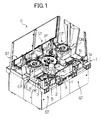
- FIG. 1 is an overhead view illustrating a game machine according to an embodiment of the present invention
- FIG. 2 is a top view illustrating a play field in which a game is played.
- a top portion and a side face portion of a game machine G are partially omitted.
- the play field of the game machine G is surrounded by a barrier such as a transparent plate, thereby shielding the play field from the outside.
- the game machine G is a so-called medal game machine in which the medal is used as a game medium.
- the game machine G includes a center unit CN and four station units ST. Each two of the station units ST are disposed across the center unit CN from each other.
- a so-called pusher game, in which the medal is used, and a digital lottery game associated with the pusher game are played in the station unit ST.
- a bonus game is played in the center unit CN in association with the game result in the station unit ST.
- the station unit ST includes a pusher field portion PF in which the pusher game is played, a medal slot potion 1 that supplies the medal to the pusher field portion PF, a medal withdrawal port 2 that withdraws the medal to a player according to the result of the pusher game, an operation button 3 that is used in a bonus game, a medal supply portion 4 serves as a dividend supply device for supplying the medal to the pusher field portion PF according to the result of the bonus game, a ball supply portion 5 that supplies a ball as a lottery medium to the pusher field portion PF according to the result of a digital lottery game, and a display portion 6 on which the digital lottery game and the like are displayed.
- the pusher field portion PF includes a table 7 and a pusher table 8, in which the medals are stored.
- the medals are stored in the table 7 and the pusher table 8 so as to be spread over the table 7 and the pusher table 8.
- the pusher table 8 is reciprocated back and forth on the table 7 (it is assumed that the front is the side on which the player is located, the same holds true for the following description).
- the medal slot potion 1 includes a medal slot 1a in which the player slots the medal and a rail 1b through which the slotted medal is guided so as to be supplied to the pusher table 8.
- the medal slot potion 1 is turnably placed in the game machine such that the player can appropriately select a medal launching direction.
- the medal supply portion 4 includes a hopper 4a (see FIG. 15 ) serves as a supply device provided in an upper portion of the medal supply portion 4 and a medal receiving member 4b serves as a dividend receiving member.
- a hopper 4a serves as a supply device provided in an upper portion of the medal supply portion 4
- a medal receiving member 4b serves as a dividend receiving member.
- the display portion 6 a reflecting mirror reflects a screen displayed on a liquid crystal display device provided above the reflecting mirror, and the screen is displayed to the player.
- the liquid crystal display device can be shared with the station unit ST located on the opposite side.
- the display portion 6 may be a display device such as the liquid crystal display device.
- FIG. 3 is a perspective view illustrating the pusher field portion PF.
- An inclined portion 11 is provided in front of the pusher table 8 while continuing to the medal storage portion 8a of the pusher table 8.
- Chance checkers 12 are provided in the inclined portion 11 in order to detect passage of a medal M.
- Each chance checker 12 includes a lamp 12a that is lit or turned off according to the detection of the medal M.
- An inclined portion 13 is provided in front of the table 7 while continuing to the medal storage portion 7a of the table 7.
- the inclined portion 13 includes a start checker 14 and a pair of flippers 15.
- the start checker 14 detects approach of the medal M.
- the flippers 15 are provided on both sides of the start checker 14 to guide the medal M to the start checker 14.
- the start checker 14 detects the approach of the medal M to an opening portion 14a provided in the inclined portion 13.
- the pair of flippers 15 is opened and closed according to the result of the pusher game or digital lottery game to change the ease of the approach of the medal M to the start checker 14.
- the medal M of the chance checker 12 or start checker 14 may be detected by utilizing well-known sensor techniques such as a photoelectric sensor.
- a schematic flow of the medal M in the pusher field portion PF will be described below.
- the medal M is guided to the rail 1b to drop on the medal storage portion 8a of the pusher table 8, and the medal M is stored in the medal storage portion 8a or the medal M rolls down from the pusher table 8 to the table 7.
- the group of medals M stored on the pusher table 8 comes into contact with a wall portion 16 and pushed forward by a reciprocating movement of the pusher table 8. Therefore, the medal M is pushed out from a front end of the pusher table 8, the pushed-out medal M slips off the inclined portion 11 to pass through one of the chance checkers 12, and the medal M is moved to and stored on the table 7.
- the game content played in the passage of the medal M is set to each chance checker 12, and each chance checker 12 is displayed such that the player can notice by the lamp 12a.
- the flippers 15 are opened and closed according to the setting of the chance checker 12.
- the group of medals M stored on the table 7 is pushed forward by the reciprocating movement of the pusher table 8. Therefore, the medal M is pushed out from the front end of the table 7, the medal M slips off the inclined portion 13 to drop off, and the medal M is withdrawn from the medal withdrawal port 2 through a count hopper (not illustrated) to the player.
- the digital lottery game is a kind of slot game that plays whether a combination of three drawing patterns (such as pictures, symbols, and figures) horizontally displayed in line on the display portion 6 is matched with a predetermined prize.
- the digital lottery game is coordinated with the chance checker 12 such that a lottery condition is changed according to the setting of the chance checker 12 by which the medal M is detected.
- a stage management may be performed such that the digital lottery game is coordinated with the flippers 15.
- a "ball” is prepared as one of the prizes of the digital lottery game. For example, when the three drawing patterns of the ball are lined up, the prize of the "ball” is won, and a ball B1 is supplied to the table 7 from the ball supply portion 5.
- the ball B1 may be made of a resin or the like, and the ball B1 may be separated by colors.
- the ball B1 supplied on the table 7 is gradually pushed out toward the front side of the table 7 along with the medals M by the reciprocating movement of the pusher table 8.
- the ball B1 slips off the inclined portion 13.
- the slipped-off ball B1 is detected by a detection portion (not illustrated) to give a predetermined dividend to the player.
- the dividend is withdrawn from the withdrawal portion 17.
- the well-known sensor techniques such as a photoelectric sensor and a proximity sensor may be used in the detection portion.
- the slipped-off ball B1 is counted based on the detection result, and the bonus game is started in the center unit CN when the number of balls B1 reaches a predetermined value.
- the bonus game may be started when the slipped-off ball B1 goes into the start checker 14.
- a "direct bonus game” may be prepared as one of the prizes of the digital lottery game. For example, when the three letters "D" of the alphabet are lined up, the prize of the "direct bonus game” is won, and the bonus game is started in the center unit CN.
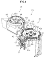
- FIG. 4 is a perspective view illustrating the center unit CN.
- the center unit CN includes a bonus field portion BF serves as a first game region and a chance field portion CF serves as a second game region.
- the bonus game is played in the bonus field portion BF.
- the two chance field portions CF are provided in the game machine G, and the chance game associated with the result of the bonus game is played in the chance field portion CF.
- a ball B2 is used as an object.
- the ball B2 is made of metal. Because the chance field portions CF have similar configurations, only one chance field portion CF is illustrated in FIG. 4 .
- a ball input portion 21, a bonus game region A1, an out zone A2, and a ball conveying mechanism 22 are provided in the bonus field portion BF.
- the ball input portion 21 is used to puts in the ball B2.
- the bonus game region A1 serves as a game region, a prize winning opportunity can be generated by the physical motion of the ball B2 put in from the ball input portion 21.
- the ball B2 is discharged from the bonus game region A1 and stored in the out zone A2.
- the ball conveying mechanism 22 conveys the ball B2 from the bonus field portion BF to the chance field portion CF.
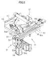
- FIG. 5 illustrates a detail of the ball input portion 21.
- the ball input portion 21 includes a launching portion 31 that launches the ball B2 toward the bonus game region A1 and a rail 32 that guides the launched ball B2 to the bonus game region A1.
- the launching portion 31 includes a push-out member 33 that pushes out the ball B2 and a solenoid 34 that drives the push-out member 33.
- the push-out member 33 has a U-shape, and pushed out the ball by one of end portions of the push-out member 33 to launch the ball B2.
- a shaft 33a fixed to the game machine G is provided in a folded portion below the push-out member 33, the push-out member 33 is driven by the operation of the solenoid 34 coupled to the other end portion of the push-out member 33, and one of the end portions pushes out the ball B2.
- the solenoid 34 vertically drives an iron core 34a in a reciprocating manner by magnetic excitation of the built-in solenoid coil and release of the magnetic excitation.
- the iron core 34a is coupled to the other end portion of the push-out member 33.
- the rail 32 includes a rail bottom 35 and a pair of rail side plates 36a and 36b that are provided perpendicular to the rail bottom 35 on both sides of the rail bottom 35.
- the rail bottom 35 and the rail side plates 36a and 36b constitute a moving path of the ball B2.
- An opening 36b1 is provided in part of the rail side plate 36b in order to supply the ball B2 to be launched.
- a bonus game board surface 41 serves as a mortar-shape game board surface
- a bumper 42 serves as first game device or a lottery mechanism that is provided on the bonus game board surface 41 to flip the ball B2
- a fence 43 serves as the barrier that surrounds the outer periphery of the bonus game board surface 41 are provided in the bonus game region A1.
- the bonus game board surface 41 includes a rotating disc 41a (see FIG. 2 ) that is provided in the center of the bonus game board surface 41 to be rotated and projections 41b that disposed around the rotating disc 41a.
- the rotating disc 41a is rotated at a predetermined rotating speed to change the moving direction of the ball B2 coming into contact with the rotating disc 41a.
- a mound may be provided on a surface of the rotating disc 41a.
- the moving direction of the ball B2 coming into contact with the rotating disc 41a is changed according to rotating timing of the rotating disc 41a.
- the four projections 41b are provided, and the projection 41b has a semi-elliptical shape.
- the projection 41b changes the moving direction of the ball B2 coming into contact with the projection 41b.
- the bumper 42 is a so-called thumper bumper, and the bumper 42 includes a ball detection portion 42a and a lamp 42b.
- the ball detection portion 42a serves as an object detection device that detects the ball B2 coming into contact with the ball detection portion 42a.
- the lamp 42b displays the detection of the ball B2.
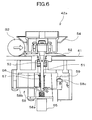
- FIG. 6 illustrates a detail of an internal mechanism of the ball detection portion 42a.
- the ball detection portion 42a includes a rod 51, a bracket 52, a rod support spring 53, a push-out plate 54, a solenoid 55, an iron core rod 56, a spring 57, a lever 58, and a bumper sensor 59.
- the rod 51 is vertically provided in the bumper 42.
- the bracket 52 is provided in the upper portion of the rod 51.
- the rod support spring 53 serves as a spring that supports the rod 51.
- the push-out plate 54 serves as a push-out member that is vertically slidable with respect to the bumper 42, and the push-out plate 54 outwardly flicks the ball B2 that is contacted with the push-out plate 54 when being slid downward.
- the solenoid 55 serves as a drive device for driving the push-out plate 54.
- the upper end of the iron core rod 56 is fixed to the push-out plate 54, the lower end of the iron core rod 56 is pierced through the solenoid 55, and the iron core rod 56 is lowered by attraction of the solenoid 55 when the solenoid 55 is energized.
- the spring 57 elevates the iron core rod 56 when the solenoid 55 is not energized.
- the bumper sensor 59 serves as a detection portion that detects a displacement of the lever 58.
- the rod 51 is swingably supported by the rod support spring 53.
- the bracket 52 having a disc shape is fixed to the rod 51 while being able to be swung along with the rod 51.
- the upper surface of bracket 52 is inclined so as to be elevated toward the center of the bumper 42.
- the lower surface of the push-out plate 54 is inclined so as to be lowered toward the center of the bumper 42. That is, an interval between the bracket 52 and the push-out plate 54 is narrowed toward the center of the bumper 42.
- the lever 58 includes a lever center portion 58a, an arm portion 58b, and a detected portion 58c.
- the lever center portion 58a serves as a mortar-shape center portion.
- One of end portions of the arm portion 58b is fixed to swingably support the lever center portion 58a.
- the detected portion 58c is provided in the other end portion.
- the lever center portion 58a comes into contact with the end portion of the rod 51.
- the bumper sensor 59 detects a displacement of the detected portion 58c.
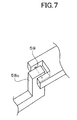
- FIG. 7 is a perspective view of the bumper sensor 59.
- Various reflection type or transmission type photoelectric sensors are used as the bumper sensor 59. Usually inspection light is blocked. When the detected portion 58c is moved downward, the inspection light is in a non-blocked state, and a signal for detecting the displacement of the detected portion 58c is supplied.
- the lamp 42b is lit or turned off based on a detection signal supplied from the bumper sensor 59. Therefore, the contact with the ball B2 is displayed to the player.
- the fence 43 is a wall that prevents a deviation of the ball B2 from the bonus game region A1, and the fence 43 is partially provided in the outer periphery of the bonus game board surface 41.
- the fence 43 is made of a resin, rubber, metal, or the like, and the fence 43 rebounds the ball B2 colliding with the fence 43.
- the fence 43 may be formed by an inclined surface having a steep slant instead of the wall. Even if the ball B2 is moved toward the outside, the ball B2 is accelerated by a gravitational force and returned to the center side.
- the fence 43 may have any configuration as long as the ball B2 is returned to the center side of the bonus game board surface 41.
- the out zone A2 is provided adjacent to the outer periphery of the bonus game board surface 41.
- the two out zones A2 are provided on both sides across the center of the bonus game board surface 41.
- An out blocker 61 and a ball storage portion 62 are provided in the out zone A2.
- the out blocker 61 serves as discharge adjusting device for preventing the discharge of the ball B2 from the bonus game region A1, and the out blocker 61 can appear and disappear from the out zone A2.
- the ball storage portion 62 stores the discharged ball.
- FIG. 8 illustrates a detail of the out blocker 61. In FIG. 8 , four out blockers 61 are provided.
- the number of out blockers 61 is not limited to four, however the out blockers 61 may appropriately be placed according to an area of the out zone A2.
- the out blocker 61 is placed near a boundary with the bonus game region A1.
- the out blocker 61 includes a block plate 63 that serves as a movable member for preventing the discharge of the ball B2, a solenoid 64 that drives the block plate 63, a coupling member 65 that couples the block plate 63 and the solenoid 64, and a block sensor 66 that detects collision of the ball B2 with the block plate 63.
- the block plate 63 is provided in a discharge port 63a in which the fence 43 is not provided, and the block plate 63 vertically appears in and disappears from the ball moving surface of the out zone A2.
- the solenoid 64 has a configuration similar to that of the solenoid 34 of the ball input portion 21 to reciprocate an iron core 64a.
- each block plate 63 is always biased in a direction in which the block plate 63 disappears by a spring (not illustrated), and the block plate 63 is disappears from the ball moving surface by the spring force when the current is not passed through the solenoid 64.
- the block plate 63 appears on the ball moving surface against the spring force.
- the coupling member 65 can be rotated around a shaft (not illustrated), and both ends of the coupling member 65 are coupled to block plate 63 and the iron core 64a.
- the shaft is shared by the out blockers 61.
- the coupling member 65 When the iron core 64a is driven by the conduction state or non-conduction state of the solenoid 64, the coupling member 65 is rotated around the shaft while coordinating with the iron core 64a. Therefore, the block plate 63appears and disappears vertically.
- the block sensor 66 detects the collision of the ball B2 with the block plate 63 by a limit switch. Various well-known techniques such as a sensor and a switch may be used in the block sensor 66.
- the ball B2 is passed through the out blocker 63 while the movement is not prevented because the out blocker 63 disappears, and the ball B2 is stored in the ball storage portion 62. As illustrated in FIG. 5 , the ball storage portion 62 is provided adjacent to the ball input portion 21.
- the ball storage portion 62 is configured such that the stored ball B2 is guided to the opening 36b1 of the rail 32 of the ball input portion 21.
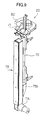
- FIGS. 9 and 10 illustrate a detail of the ball conveying mechanism 22.
- FIG. 9 illustrates the ball conveying mechanism when viewed from the right front side
- FIG. 10 illustrates the ball conveying mechanism when viewed from the right rear side.
- the ball conveying mechanism 22 is provided adjacent to the outer periphery of the bonus game board surface 41.
- the ball conveying mechanism 22 includes a drop hole 71 in which the ball B2 can drop, a conveying rod 72 that conveys the dropped ball B2 to the chance field portion CF, and a linear drive mechanism 73 that vertically drives the conveying rod 72.
- the drop hole 71 is provided on a surface connected to the ball moving surface of the bonus game board surface 41, and the ball B2 moved from the bonus game region A1 can drop in the drop hole 71.
- the drop hole 71 includes a drop sensor (not illustrated) that detects the drop of the ball B2.
- a drop sensor (not illustrated) that detects the drop of the ball B2.
- Various well-known techniques such as a photoelectric sensor may be used in the drop sensor.
- the conveying rod 72 is vertically driven to appear from and disappear in the drop hole 71.
- the conveying rod 72 is located below the drop hole 71 to wait for the dropped ball B2, and the conveying rod 72 is driven upward to convey the ball B2 to the chance field portion CF based on the detection signal supplied from the drop sensor.
- a ball conveying surface 72a (see FIG. 4 ) of the conveying rod 72 is obliquely cut such that the side of the chance field portion CF is lowered.
- the ball B2 is stably placed on the ball conveying surface 72a and conveyed, while the ball B2 is supported by a ball support member 72b (see FIG. 4 ) provided along the conveying rod 72 on the side of the chance field portion CF.
- the linear drive mechanism 73 includes a rail 73a that is vertically fixed, a slider 73b that can be moved along the rail 73a, and a motor 73c that drives the slider 73b.
- Various commercially available electric motors may be used as the motor 73c.
- a linear actuator or a linear motor may be used as the linear drive mechanism 73.
- the conveying rod 72 is fixed to the slider 73b, and the slider 73b is moved along the rail 73a by the operation of the motor 73c, thereby driving the conveying rod 72.
- the chance field portion CF includes a chance game board surface 81 serves as a rotatable second game device and lottery holes 82 that are provided near the center of the chance game board surface 81.
- a slope is formed so as to be lowered toward the center.
- the chance game board surface 81 is rotated by a motor (not illustrated) or the like.
- the lottery hole 82 has a size in which the ball B2 can drop, and the lottery hole 82 includes a lottery hole sensor 82a that detects the dropped ball B2.
- Various well-known techniques such as a photoelectric sensor may be used in the lottery hole sensor 82a.
- the game content is changed according to the setting of the lottery hole 82 in which the ball B2 drops.
- a schematic flow of the ball B2 in the center unit CN will be described.
- the ball B2 is supplied to the ball input portion 21 from the ball storage portion 62.
- the launching portion 31 launches the ball B2 to the bonus game region A1.
- the moving direction of the launched ball B2 is changed on the bonus game board surface 41 while the ball B2 comes into contact with the rotating disc 41a and projection 41b, and the ball B2 comes repeatedly into contact with and collides with the bumper 42 and the fence 43.
- the dividend to the player is generated when the ball B2 comes into contact with the bumper 42.
- a predetermined number of medals M are supplied to the table 7 from the medal supply portion 4.
- the ball B2 can come into contact with the bumper 42 plural times.
- a predetermined number of block plates 63 of the out blocker 61 appear with respect to the out zone A2 so as to prevent the discharge of the ball B2.
- the block plate 63 disappears with respect to the out zone A2. Therefore, at a first time, the ball B2 going to the out zone A2 is prevented from being discharge to the out zone A2 by the out blocker 61. However, the block plate 63 disappears due to the contact at the first time.
- the ball B2 goes to the out zone A2 at a second time, the ball B2 is directly moved to the ball storage portion 62 while the movement of the ball B2 is not obstructed by the out blocker 61, and the bonus game is ended.
- the ball B2 is conveyed to the chance field portion CF to start the chance game.
- the chance game is a so-called roulette game in which the ball B2 is used.
- the conveyed ball B2 is put in the chance game board surface 81, and the ball B2 is gradually moved to the center while circling by the rotation of the chance game board surface 81, and the ball B2 drops in one of the lottery holes 82.
- the game content is changed according to the setting of the lottery hole 82 in which the ball B2 drops.
- the dividend may be generated to the player.
- the ball B2 that drops in the lottery hole 82 is returned to the bonus game region A1 from the ball return portion 83 (see FIG. 4 ), and the bonus game is resumed.
- the bonus game may be resumed by putting in the ball B2 from the ball input portion 21.
- the conveying rod 72 of the ball conveying mechanism 22 may appear from the drop hole 71 according to the setting. In such cases, the transition to the chance game is prevented because the ball B2 does not drop in the drop hole 71. Therefore, the lottery probability can be adjusted.
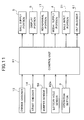
- FIG. 11 is a block diagram illustrating the configuration of the control system of the game machine G.
- the game machine G includes a control unit 91 that performs various control processes in order to play a predetermined game.
- the chance checker 12, the start checker 14, the bumper sensor 57, the lottery hole sensor 82a, and the operation button 3 serve as input devices to the control unit 91 are connected to the control unit 91.
- the ball supply portion 5, the display portion 6, the withdrawal portion 17, the medal supply portion 4, the ball input portion 21, and the out blocker 61 serve as control targets of the control unit 91 are connected to the control unit 91.
- the digital lottery game performed by the control unit 91 will be described with reference to FIG. 12 .
- the digital lottery game is played on the condition that the start checker 14 detects the medal M.
- the control unit 91 performs the slot lottery.
- Each of the three drawing patterns is determined using a random number and the like.
- the control unit 91 determines whether the prize of the "ball" is won. When the prize of the "ball" is won, the control unit 91 goes to Step S3, the control unit 91 directs the ball supply portion 5 to supply the ball B1, and the present process is ended.
- Step S4 When the prize of the "ball" is not won in Step S2, the control unit 91 goes to Step S4, and the control unit 91 determines whether the prize of the "direct bonus game” is won. When the prize of the "direct bonus game” is won, the control unit 91 goes to Step S5, the control unit 91 provides an instruction to start the bonus game in the bonus game region A1, and the present process is ended. When the prize of the "direct bonus game” is not won in Step S4, the control unit 91 performs a process according to the result of the slot lottery in Step S6. When the prizes are not won, the control unit 91 performs nothing, and the present process is ended. When the predetermined prize is won, the control unit 91 changes the game content according to the prize, and the present process is ended.
- the transition to the bonus game is made based on the lottery result of the digital lottery game. Because the bonus game is positioned as a specific benefit in the digital lottery game, the player is motivated to play the digital lottery game.
- the chance game performed by the control unit 91 will be described with reference to FIG. 13 .
- the chance game is played on the condition that the drop sensor of the ball conveying mechanism 22 detects the ball B2 to convey the ball B2 from the bonus field portion BF to the chance field portion CF.
- the control unit 91 performs the roulette lottery.
- the ball B2 drops in one of the lottery holes 82, and the lottery hole sensor 82a detects the ball B2.
- Step S12 the control unit 91 performs a process according to the result of the roulette lottery, and the present process is ended.
- the control unit 91 changes the game content based on the setting of the lottery hole sensor 82a that detects the ball B2. Examples of the prize may include a lottery game in which the player expects the high dividend and the withdrawal of the medal M.
- a game that the players of all the station units ST can participate may be played in the center unit CN.
- the chance game that is different from the bonus game is started during the bonus game.
- the chance game is positioned as a specific benefit in the bonus game, and the dividend opportunity is further provided to the player. Therefore, the player is motivated to play the bonus game.
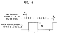
- FIG. 14 is a view schematically illustrating a relationship between the prize winning interval between the two games and a dividend amount.
- the prize is won to generate the dividend to the player.
- the bumper 42 flips the ball B2, so that the ball B2 can repeatedly come into contact with the bumper 42 while moving on the bonus game board surface 41. Therefore, a prize winning interval Pn from the prize to the next prize is shortened.
- a dividend amount N may be relatively small. That is, a small amount of dividend is generated plural times, and the expectation of the player for the continuous prize winning is enhanced while the dividend is restrained, so that the interest in the game can be increased.
- a lottery time Lm necessary for the lottery until the ball B2 drops in the lottery hole 82 since the ball B2 is put on the chance game board surface 81 is longer than the prize winning interval Pn of the bonus game.
- a dividend amount M is also larger than the dividend amount N of the bonus game. Therefore, because speedy development of the game is provided in the bonus game while the slow lottery is performed in the chance game, the game attracts the player while the development of the game is not monotonized, and the interest in the game can be increased.
- the out blocker 61 acts as a discharge adjusting device for adjusting the discharge of the ball B2 from the discharge port 63a.
- the control unit 91 acts as a discharge control device for operating the out blocker 61 to control the ease of the discharge of the ball B2.
- the block plate 63 supplies a signal when the block sensor detects the contact with the ball B2.
- the solenoid 64 is operated based on the output signal, and the solenoid 64 drives the block plate 63 such that the block plate 63 disappears from the ball moving surface of the bonus field portion BF.
- the ball B2 can be passed through the portion in which the block plate 63 disappears, and the ball B2 is discharged to the out zone A2 when coming to the portion again.
- the block plates 63 can individually be operated. The player becomes difficult to play the game in the bonus game region A1 as the number of disappeared block plates 63 is increased.
- the number of appearing block plates 63 may be determined according to the result of the digital lottery game.
- the control unit 91 may control the out blocker 61 in a normal state such that the two block plates 63 are caused to appear at the beginning of the bonus game, and the control unit 91 may control the out blocker 61 in a probability fluctuating state in which the prize winning probability is set higher such that the four block plates 63 are caused to appear at the beginning of the bonus game.
- the prize winning probability can be controlled in the bonus game by changing the number of appearing block plates 63 at the beginning of the bonus game.
- the control unit 91 may control the out blocker 61 such that the number of contacts of the ball B2 is set to plural times until the block plate 63 disappears.
- the control unit 91 may control the prize winning probability in the bonus game by setting an appearance time of the block plate 63 to a predetermined time.
- the prize winning probability can be varied in the bonus game according to the appearance condition of the out blocker 61, the passion for gambling can be raised in the game, and the interest in the game can be increased.
- the ease of the discharge of the ball B2 is controlled by the control unit 91 as described above, so that the adjustment of the lottery probability can be achieved.
- the lever center portion 58a that is of the contact point with the end portion of the rod 51 has a mortar shape
- the lever center portion 58a can deal with the contact of the bumper 42 with the ball B2 from all the directions, and the detected portion 58c of the lever 58 can be moved downward from all the directions.
- the solenoid 55 is energized in conjunction with detection of the contact of the bumper 42 with the ball B2, and the iron core rod 56 is attracted downward.
- the push-out plate 54 fixed to the upper end of the iron core rod 56 is slid downward, the ball B2 is pushed out and flicked to the outward direction by the slant surface of the peripheral edge of the push-out plate 54.
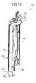
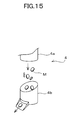
- FIG. 15 is a perspective view of the medal supply portion 4.
- the medal supply portion 4 is placed between the pusher field portion PF and the bonus field portion BF. That is, the medal supply portion 4 is placed at the position where the medal supply portion 4 comes into sight of the player when the player sees the bonus field portion BF.
- the stage management is performed such that the medal M drops before the player' s eyes, and the medal M is supplied to the table 7 through the medal receiving member 4b. Therefore, the withdrawal of the medal M can effectively be stage-managed to the player, and the interest in the game can be increased.
- the game in the center unit CN is played by utilizing the physical motion of the ball B2, however not limited to it.
- the game in the center unit CN may be a digital lottery game displayed by a liquid crystal display device and the like.
- a game that is not the physical game may be played when the prize winning interval between the bonus game and the chance game is similar to that of the embodiment.
- the digital lottery game may be adopted in one of the bonus game and the chance game while the physical lottery game is adopted in the other.
- the ball used in the bonus field portion BF be identical to the ball used in the chance field portion CF.
- different types of balls may separately be used in the bonus field portion BF and the chance field portion CF.
- the motion of the ball may be changed using a plurality of balls having different characteristics such as a mass and a friction coefficient.
- the object is not limited to the ball, however the medal M may be used as the object.
- the ellipsoidal or polyhedral object may be used.
- the chance game played in the chance field portion CF is not limited to the roulette game.
- the chance game board surface 81 is not limited to the rotating board surface, however the board surface may be deformed so as to heave up, or the board surface may be oscillated. In such cases, the ball B2 can be rotated on the board surface, and which lottery hole the ball B2 drops in cannot be expected. Therefore, the game can attract the player. Lottery holes may be openable. Which lottery hole the ball B2 drops in cannot further be expected. Therefore, the interest in the game can further be increased.
Abstract
A game machine G comprise a bumper 42 (a first game device) that is provided in a bonus field portion BF as a first game region, and that can repeatedly generate a prize winning opportunity, and that generates a predetermined dividend in each prize winning, and a chance game board surface 81 and plural lottery holes 82 (a second game means) that are provided in a chance field portion CF as a second game region, and that generates prize winning having a dividend larger than the predetermined dividend, a time until the prize winning since start of a lottery being longer than an average prize winning interval of the bumper 42.
Description
- The present invention relates to a game machine including game devices for generating a dividend.
- For example, there is well known a game machine in which a player slots a game medium such as a medal to play a predetermined game (for example, see Patent Document 1). In such game machines, sometimes a prize winning having relatively small dividend is generated little by little in order to raise passion for gambling of a player.
- Patent Document 1: Japanese Patent Application Laid-Open No.
2005-224326 - In the game machine described above, although the game attracts the player for a long time because the prize winning is generated little by little, the player is possibly distracted from the game because of sluggish progress of the game. Although a prize winning occurrence interval may be narrowed, the player reaches a dividend amount that should be given to the player in a short time. Therefore, possibly the game cannot attract the player for a long time.
- In view of the foregoing, an object of the present invention is to provide a game machine that can generate the prize winning in a wide variety of timing.
- A game machine according to an aspect of the present invention solves the above described problem by comprising: a first game device that is provided in a first game region, and that can repeatedly generate a prize winning opportunity, and that generates a predetermined dividend in each prize winning; and a second game device that is provided in a second game region , and that generates prize winning having a dividend larger than the predetermined dividend, a time until the prize winning since start of a lottery being longer than an average prize winning interval of the first game device.
- Accordingly, in the first game device, speedy development of the game can be performed because the prize winning opportunity can repeatedly be generated. Therefore, it is possible that the expectation of the player for the continuous prize winning is raised. On the contrary, in the second game device, it is possible that the expectation of the player for the continuous prize winning with a high dividend is raised because the progress of the game is slower than that of the first game device. Therefore, the prize winning can be generated in a wide variety of timing.
- In the game machine according to an aspect of the present invention, the first game device may utilize a physical motion of an object that can be moved on a board surface of the first game, and the second game device may utilize a physical motion of an object that can be moved on a board surface of the second game to generate the prize winning opportunity.. Accordingly, in each of the game device, the game is played by utilizing the physical motion of the object. The player plays the game while visually recognizing the physical motion of the object, so that the game can attract the player to increase an interest in the game.
- In the game machine using the physical motion of an object according to an aspect of the present invention, the object may be allowed to move between the first and second game device. Since the object can be moved between the game devices, the continuous game is played. Accordingly, the second game device can provide the slow development of the game as an extension of the speedy development of the game in the first game device, and inflection is imparted to the development of the game, so that the game can attract the player.
- In the game machine according to an aspect of the present invention, the object may be a ball. Accordingly, the object is a ball, so that the ball can smoothly be moved in each game region.
- In the game machine using the ball as the object according to an aspect of the present invention, the first game device may be a bumper that generates a dividend by contact of the ball. The first game device is the bumper, so that the ball can repeatedly come into contact with the bumper in the first game region.
- In the game machine in which the bumper is provided according to an aspect of the present invention, the bumpers may be provided in the first game region. A larger number of prize winning opportunities can be generated by providing the bumpers, and the passion for gambling can be raised.
- In the game machine in which the bumper is provided according to an aspect of the present invention, the bumper may rebounds the contacted ball while the ball is biased. Accordingly, because the bumper flips the contacted ball, a moving force is given to the ball, and the ball can restlessly be moved in the first game region.
- In the game machine using the ball as the object according to an aspect of the present invention, the second game device may include a game board surface in which the ball can be rotated; and lottery holes that are provided on the game board surface, the ball being able to drop in the lottery holes. Accordingly, the ball drops eventually in one of the lottery holes while being moved on the game board surface. The time until the prize winning since the start of the lottery is lengthened, so that the progress of the game can be slowed.
- In the game machine according to an aspect of the present invention, the game board surface may be configured to be rotatable and serves as a roulette, the second game device may be the roulette. Accordingly, the second game device is the roulette, so that the slow development of the game can be provided.
- Thus, in the game machine of the present invention, the speedy development of the game can be performed in the first game device because the prize winning opportunity can repeatedly be generated. Therefore, it is possible that the expectation of the player for the continuous prize winning is raised. On the contrary, in the second game device, it is possible that the expectation of the player for the continuous prize winning with a high dividend is raised because the progress of the game is slower than that of the first game device. Therefore, the prize winning can be generated in a wide variety of timing, and the interest in the game can be increased to attract the player to the game for a long time.
-
-
FIG. 1 is an overhead view illustrating a game machine according to an embodiment of the present invention. -
FIG. 2 is a top view illustrating a play field in which a game is played. -
FIG. 3 is a perspective view of a pusher field portion. -
FIG. 4 is a perspective view of a center unit. -
FIG. 5 illustrates a detail of a ball input portion. -
FIG. 6 illustrates a detail of an internal mechanism of a ball detection portion. -
FIG. 7 is a perspective view of a bumper sensor. -
FIG. 8 illustrates a detail of an out blocker. -
FIG. 9 illustrates a detail of a ball conveying mechanism. -
FIG. 10 illustrates a detail of a ball conveying mechanism. -
FIG. 11 is a block diagram illustrating a configuration of a control system of the game machine. -
FIG. 12 is a flowchart illustrating a digital lottery game. -
FIG. 13 is a flowchart illustrating a chance game. -
FIG. 14 is a view illustrating a prize winning interval between a bonus game and a chance game. -
FIG. 15 is a perspective view of a medal supply portion. -
FIG. 1 is an overhead view illustrating a game machine according to an embodiment of the present invention, andFIG. 2 is a top view illustrating a play field in which a game is played. InFIG. 1 , for the sake of convenience, a top portion and a side face portion of a game machine G are partially omitted. The play field of the game machine G is surrounded by a barrier such as a transparent plate, thereby shielding the play field from the outside. The game machine G is a so-called medal game machine in which the medal is used as a game medium. The game machine G includes a center unit CN and four station units ST. Each two of the station units ST are disposed across the center unit CN from each other. A so-called pusher game, in which the medal is used, and a digital lottery game associated with the pusher game are played in the station unit ST. A bonus game is played in the center unit CN in association with the game result in the station unit ST. - The station unit ST includes a pusher field portion PF in which the pusher game is played, a medal slot potion 1 that supplies the medal to the pusher field portion PF, a
medal withdrawal port 2 that withdraws the medal to a player according to the result of the pusher game, anoperation button 3 that is used in a bonus game, amedal supply portion 4 serves as a dividend supply device for supplying the medal to the pusher field portion PF according to the result of the bonus game, aball supply portion 5 that supplies a ball as a lottery medium to the pusher field portion PF according to the result of a digital lottery game, and adisplay portion 6 on which the digital lottery game and the like are displayed. The pusher field portion PF includes a table 7 and a pusher table 8, in which the medals are stored. The medals are stored in the table 7 and the pusher table 8 so as to be spread over the table 7 and the pusher table 8. The pusher table 8 is reciprocated back and forth on the table 7 (it is assumed that the front is the side on which the player is located, the same holds true for the following description). The medal slot potion 1 includes amedal slot 1a in which the player slots the medal and arail 1b through which the slotted medal is guided so as to be supplied to the pusher table 8. The medal slot potion 1 is turnably placed in the game machine such that the player can appropriately select a medal launching direction. Because the two medal slot potions 1 are placed in each station unit ST, the game can be played in one station unit ST by up to two players. Themedal supply portion 4 includes ahopper 4a (seeFIG. 15 ) serves as a supply device provided in an upper portion of themedal supply portion 4 and amedal receiving member 4b serves as a dividend receiving member. When the medal is withdrawn from thehopper 4a, the medal drops on themedal receiving member 4b, and the medal is supplied to the pusher field portion PF. In thedisplay portion 6, a reflecting mirror reflects a screen displayed on a liquid crystal display device provided above the reflecting mirror, and the screen is displayed to the player. In this case, the liquid crystal display device can be shared with the station unit ST located on the opposite side. Thedisplay portion 6 may be a display device such as the liquid crystal display device. -
FIG. 3 is a perspective view illustrating the pusher field portion PF. Aninclined portion 11 is provided in front of the pusher table 8 while continuing to themedal storage portion 8a of the pusher table 8.Chance checkers 12 are provided in theinclined portion 11 in order to detect passage of a medal M. Eachchance checker 12 includes alamp 12a that is lit or turned off according to the detection of the medal M. Aninclined portion 13 is provided in front of the table 7 while continuing to themedal storage portion 7a of the table 7. Theinclined portion 13 includes astart checker 14 and a pair offlippers 15. Thestart checker 14 detects approach of the medal M. Theflippers 15 are provided on both sides of thestart checker 14 to guide the medal M to thestart checker 14. Thestart checker 14 detects the approach of the medal M to anopening portion 14a provided in theinclined portion 13. The pair offlippers 15 is opened and closed according to the result of the pusher game or digital lottery game to change the ease of the approach of the medal M to thestart checker 14. The medal M of thechance checker 12 or startchecker 14 may be detected by utilizing well-known sensor techniques such as a photoelectric sensor. - A schematic flow of the medal M in the pusher field portion PF will be described below. When the player slots the medal M in the
medal slot 1a, the medal M is guided to therail 1b to drop on themedal storage portion 8a of the pusher table 8, and the medal M is stored in themedal storage portion 8a or the medal M rolls down from the pusher table 8 to the table 7. The group of medals M stored on the pusher table 8 comes into contact with awall portion 16 and pushed forward by a reciprocating movement of the pusher table 8. Therefore, the medal M is pushed out from a front end of the pusher table 8, the pushed-out medal M slips off theinclined portion 11 to pass through one of thechance checkers 12, and the medal M is moved to and stored on the table 7. - The game content played in the passage of the medal M is set to each
chance checker 12, and eachchance checker 12 is displayed such that the player can notice by thelamp 12a. Theflippers 15 are opened and closed according to the setting of thechance checker 12. The group of medals M stored on the table 7 is pushed forward by the reciprocating movement of the pusher table 8. Therefore, the medal M is pushed out from the front end of the table 7, the medal M slips off theinclined portion 13 to drop off, and the medal M is withdrawn from themedal withdrawal port 2 through a count hopper (not illustrated) to the player. - When the
start checker 14 detects the medal M that is pushed out from the front end of the table 7 to go into thestart checker 14, the digital lottery game is started. The digital lottery game is a kind of slot game that plays whether a combination of three drawing patterns (such as pictures, symbols, and figures) horizontally displayed in line on thedisplay portion 6 is matched with a predetermined prize. The digital lottery game is coordinated with thechance checker 12 such that a lottery condition is changed according to the setting of thechance checker 12 by which the medal M is detected. A stage management may be performed such that the digital lottery game is coordinated with theflippers 15. When the predetermined prize is won as a result of lottery to generate a dividend to the player, the dividend is withdrawn from awithdrawal portion 17 provided above thedisplay portion 6. The withdrawn medal M slips off thedisplay portion 6 to drop on the pusher table 8. - A "ball" is prepared as one of the prizes of the digital lottery game. For example, when the three drawing patterns of the ball are lined up, the prize of the "ball" is won, and a ball B1 is supplied to the table 7 from the
ball supply portion 5. The ball B1 may be made of a resin or the like, and the ball B1 may be separated by colors. - The ball B1 supplied on the table 7 is gradually pushed out toward the front side of the table 7 along with the medals M by the reciprocating movement of the pusher table 8. When the ball B1 drops from the front end of the table 7, the ball B1 slips off the
inclined portion 13. Then the slipped-off ball B1 is detected by a detection portion (not illustrated) to give a predetermined dividend to the player. The dividend is withdrawn from thewithdrawal portion 17. The well-known sensor techniques such as a photoelectric sensor and a proximity sensor may be used in the detection portion. The slipped-off ball B1 is counted based on the detection result, and the bonus game is started in the center unit CN when the number of balls B1 reaches a predetermined value. The bonus game may be started when the slipped-off ball B1 goes into thestart checker 14. A "direct bonus game" may be prepared as one of the prizes of the digital lottery game. For example, when the three letters "D" of the alphabet are lined up, the prize of the "direct bonus game" is won, and the bonus game is started in the center unit CN. -
FIG. 4 is a perspective view illustrating the center unit CN. The center unit CN includes a bonus field portion BF serves as a first game region and a chance field portion CF serves as a second game region. The bonus game is played in the bonus field portion BF. InFIG. 4 , the two chance field portions CF are provided in the game machine G, and the chance game associated with the result of the bonus game is played in the chance field portion CF. In the center unit CN, a ball B2 is used as an object. The ball B2 is made of metal. Because the chance field portions CF have similar configurations, only one chance field portion CF is illustrated inFIG. 4 . - A
ball input portion 21, a bonus game region A1, an out zone A2, and aball conveying mechanism 22 are provided in the bonus field portion BF. Theball input portion 21 is used to puts in the ball B2. In the bonus game region A1 serves as a game region, a prize winning opportunity can be generated by the physical motion of the ball B2 put in from theball input portion 21. The ball B2 is discharged from the bonus game region A1 and stored in the out zone A2. Theball conveying mechanism 22 conveys the ball B2 from the bonus field portion BF to the chance field portion CF. -
FIG. 5 illustrates a detail of theball input portion 21. Theball input portion 21 includes a launchingportion 31 that launches the ball B2 toward the bonus game region A1 and arail 32 that guides the launched ball B2 to the bonus game region A1. The launchingportion 31 includes a push-out member 33 that pushes out the ball B2 and asolenoid 34 that drives the push-out member 33. The push-out member 33 has a U-shape, and pushed out the ball by one of end portions of the push-out member 33 to launch the ball B2. Ashaft 33a fixed to the game machine G is provided in a folded portion below the push-out member 33, the push-out member 33 is driven by the operation of thesolenoid 34 coupled to the other end portion of the push-out member 33, and one of the end portions pushes out the ball B2. Thesolenoid 34 vertically drives aniron core 34a in a reciprocating manner by magnetic excitation of the built-in solenoid coil and release of the magnetic excitation. Theiron core 34a is coupled to the other end portion of the push-out member 33. Therail 32 includes arail bottom 35 and a pair ofrail side plates rail bottom 35 on both sides of therail bottom 35. Therail bottom 35 and therail side plates rail side plate 36b in order to supply the ball B2 to be launched. - A bonus
game board surface 41 serves as a mortar-shape game board surface, a bumper 42 serves as first game device or a lottery mechanism that is provided on the bonusgame board surface 41 to flip the ball B2, and afence 43 serves as the barrier that surrounds the outer periphery of the bonusgame board surface 41 are provided in the bonus game region A1. The bonusgame board surface 41 includes arotating disc 41a (seeFIG. 2 ) that is provided in the center of the bonusgame board surface 41 to be rotated andprojections 41b that disposed around therotating disc 41a. Therotating disc 41a is rotated at a predetermined rotating speed to change the moving direction of the ball B2 coming into contact with therotating disc 41a. A mound may be provided on a surface of therotating disc 41a. For example, when an S-shape mound 41c is provided, the moving direction of the ball B2 coming into contact with therotating disc 41a is changed according to rotating timing of therotating disc 41a. InFIG. 2 , the fourprojections 41b are provided, and theprojection 41b has a semi-elliptical shape. Theprojection 41b changes the moving direction of the ball B2 coming into contact with theprojection 41b. - The bumper 42 is a so-called thumper bumper, and the bumper 42 includes a
ball detection portion 42a and a lamp 42b. Theball detection portion 42a serves as an object detection device that detects the ball B2 coming into contact with theball detection portion 42a. The lamp 42b displays the detection of the ball B2.FIG. 6 illustrates a detail of an internal mechanism of theball detection portion 42a. Theball detection portion 42a includes arod 51, abracket 52, arod support spring 53, a push-out plate 54, asolenoid 55, aniron core rod 56, aspring 57, alever 58, and abumper sensor 59. Therod 51 is vertically provided in the bumper 42. Thebracket 52 is provided in the upper portion of therod 51. Therod support spring 53 serves as a spring that supports therod 51. The push-out plate 54 serves as a push-out member that is vertically slidable with respect to the bumper 42, and the push-out plate 54 outwardly flicks the ball B2 that is contacted with the push-out plate 54 when being slid downward. Thesolenoid 55 serves as a drive device for driving the push-out plate 54. The upper end of theiron core rod 56 is fixed to the push-out plate 54, the lower end of theiron core rod 56 is pierced through thesolenoid 55, and theiron core rod 56 is lowered by attraction of thesolenoid 55 when thesolenoid 55 is energized. Thespring 57 elevates theiron core rod 56 when thesolenoid 55 is not energized. One of end portions of thelever 58 is fixed to the bumper 42. Thebumper sensor 59 serves as a detection portion that detects a displacement of thelever 58. Therod 51 is swingably supported by therod support spring 53. Thebracket 52 having a disc shape is fixed to therod 51 while being able to be swung along with therod 51. The upper surface ofbracket 52 is inclined so as to be elevated toward the center of the bumper 42. The lower surface of the push-out plate 54 is inclined so as to be lowered toward the center of the bumper 42. That is, an interval between thebracket 52 and the push-out plate 54 is narrowed toward the center of the bumper 42. Thelever 58 includes alever center portion 58a, anarm portion 58b, and a detectedportion 58c. Thelever center portion 58a serves as a mortar-shape center portion. One of end portions of thearm portion 58b is fixed to swingably support thelever center portion 58a. The detectedportion 58c is provided in the other end portion. Thelever center portion 58a comes into contact with the end portion of therod 51. Thebumper sensor 59 detects a displacement of the detectedportion 58c.FIG. 7 is a perspective view of thebumper sensor 59. Various reflection type or transmission type photoelectric sensors are used as thebumper sensor 59. Usually inspection light is blocked. When the detectedportion 58c is moved downward, the inspection light is in a non-blocked state, and a signal for detecting the displacement of the detectedportion 58c is supplied. The lamp 42b is lit or turned off based on a detection signal supplied from thebumper sensor 59. Therefore, the contact with the ball B2 is displayed to the player. - The
fence 43 is a wall that prevents a deviation of the ball B2 from the bonus game region A1, and thefence 43 is partially provided in the outer periphery of the bonusgame board surface 41. Thefence 43 is made of a resin, rubber, metal, or the like, and thefence 43 rebounds the ball B2 colliding with thefence 43. For example, thefence 43 may be formed by an inclined surface having a steep slant instead of the wall. Even if the ball B2 is moved toward the outside, the ball B2 is accelerated by a gravitational force and returned to the center side. Thefence 43 may have any configuration as long as the ball B2 is returned to the center side of the bonusgame board surface 41. - The out zone A2 is provided adjacent to the outer periphery of the bonus
game board surface 41. In the illustrated example, the two out zones A2 are provided on both sides across the center of the bonusgame board surface 41. An outblocker 61 and aball storage portion 62 are provided in the out zone A2. The outblocker 61 serves as discharge adjusting device for preventing the discharge of the ball B2 from the bonus game region A1, and theout blocker 61 can appear and disappear from the out zone A2. Theball storage portion 62 stores the discharged ball.FIG. 8 illustrates a detail of theout blocker 61. InFIG. 8 , four outblockers 61 are provided. The number ofout blockers 61 is not limited to four, however theout blockers 61 may appropriately be placed according to an area of the out zone A2. The outblocker 61 is placed near a boundary with the bonus game region A1. The outblocker 61 includes ablock plate 63 that serves as a movable member for preventing the discharge of the ball B2, asolenoid 64 that drives theblock plate 63, acoupling member 65 that couples theblock plate 63 and thesolenoid 64, and ablock sensor 66 that detects collision of the ball B2 with theblock plate 63. Theblock plate 63 is provided in adischarge port 63a in which thefence 43 is not provided, and theblock plate 63 vertically appears in and disappears from the ball moving surface of the out zone A2. Thesolenoid 64 has a configuration similar to that of thesolenoid 34 of theball input portion 21 to reciprocate aniron core 64a. In the embodiment, eachblock plate 63 is always biased in a direction in which theblock plate 63 disappears by a spring (not illustrated), and theblock plate 63 is disappears from the ball moving surface by the spring force when the current is not passed through thesolenoid 64. When the current is passed through thesolenoid 64, theblock plate 63 appears on the ball moving surface against the spring force. Thecoupling member 65 can be rotated around a shaft (not illustrated), and both ends of thecoupling member 65 are coupled to blockplate 63 and theiron core 64a. The shaft is shared by theout blockers 61. When theiron core 64a is driven by the conduction state or non-conduction state of thesolenoid 64, thecoupling member 65 is rotated around the shaft while coordinating with theiron core 64a. Therefore, the block plate 63appears and disappears vertically. Theblock sensor 66 detects the collision of the ball B2 with theblock plate 63 by a limit switch. Various well-known techniques such as a sensor and a switch may be used in theblock sensor 66. The ball B2 is passed through theout blocker 63 while the movement is not prevented because theout blocker 63 disappears, and the ball B2 is stored in theball storage portion 62. As illustrated inFIG. 5 , theball storage portion 62 is provided adjacent to theball input portion 21. Theball storage portion 62 is configured such that the stored ball B2 is guided to the opening 36b1 of therail 32 of theball input portion 21. -
FIGS. 9 and10 illustrate a detail of theball conveying mechanism 22.FIG. 9 illustrates the ball conveying mechanism when viewed from the right front side, andFIG. 10 illustrates the ball conveying mechanism when viewed from the right rear side. Theball conveying mechanism 22 is provided adjacent to the outer periphery of the bonusgame board surface 41. Theball conveying mechanism 22 includes adrop hole 71 in which the ball B2 can drop, a conveyingrod 72 that conveys the dropped ball B2 to the chance field portion CF, and alinear drive mechanism 73 that vertically drives the conveyingrod 72. Thedrop hole 71 is provided on a surface connected to the ball moving surface of the bonusgame board surface 41, and the ball B2 moved from the bonus game region A1 can drop in thedrop hole 71. Thedrop hole 71 includes a drop sensor (not illustrated) that detects the drop of the ball B2. Various well-known techniques such as a photoelectric sensor may be used in the drop sensor. The conveyingrod 72 is vertically driven to appear from and disappear in thedrop hole 71. The conveyingrod 72 is located below thedrop hole 71 to wait for the dropped ball B2, and the conveyingrod 72 is driven upward to convey the ball B2 to the chance field portion CF based on the detection signal supplied from the drop sensor. Aball conveying surface 72a (seeFIG. 4 ) of the conveyingrod 72 is obliquely cut such that the side of the chance field portion CF is lowered. The ball B2 is stably placed on theball conveying surface 72a and conveyed, while the ball B2 is supported by aball support member 72b (seeFIG. 4 ) provided along the conveyingrod 72 on the side of the chance field portion CF. Thelinear drive mechanism 73 includes arail 73a that is vertically fixed, aslider 73b that can be moved along therail 73a, and amotor 73c that drives theslider 73b. Various commercially available electric motors may be used as themotor 73c. A linear actuator or a linear motor may be used as thelinear drive mechanism 73. The conveyingrod 72 is fixed to theslider 73b, and theslider 73b is moved along therail 73a by the operation of themotor 73c, thereby driving the conveyingrod 72. - A configuration of the chance field portion CF will be described with reference to
FIG. 4 . The chance field portion CF includes a chancegame board surface 81 serves as a rotatable second game device and lottery holes 82 that are provided near the center of the chancegame board surface 81. On the chancegame board surface 81, a slope is formed so as to be lowered toward the center. The chancegame board surface 81 is rotated by a motor (not illustrated) or the like. Thelottery hole 82 has a size in which the ball B2 can drop, and thelottery hole 82 includes alottery hole sensor 82a that detects the dropped ball B2. Various well-known techniques such as a photoelectric sensor may be used in thelottery hole sensor 82a. The game content is changed according to the setting of thelottery hole 82 in which the ball B2 drops. - A schematic flow of the ball B2 in the center unit CN will be described. When the bonus game is started, the ball B2 is supplied to the
ball input portion 21 from theball storage portion 62. When the player presses theoperation button 3, the launchingportion 31 launches the ball B2 to the bonus game region A1. The moving direction of the launched ball B2 is changed on the bonusgame board surface 41 while the ball B2 comes into contact with therotating disc 41a andprojection 41b, and the ball B2 comes repeatedly into contact with and collides with the bumper 42 and thefence 43. The dividend to the player is generated when the ball B2 comes into contact with the bumper 42. A predetermined number of medals M are supplied to the table 7 from themedal supply portion 4. In the bonus game region A1, the ball B2 can come into contact with the bumper 42 plural times. - At the beginning of the bonus game, a predetermined number of
block plates 63 of theout blocker 61 appear with respect to the out zone A2 so as to prevent the discharge of the ball B2. When the ball B2 comes into contact with theblock plate 63, theblock plate 63 disappears with respect to the out zone A2. Therefore, at a first time, the ball B2 going to the out zone A2 is prevented from being discharge to the out zone A2 by theout blocker 61. However, theblock plate 63 disappears due to the contact at the first time. When the ball B2 goes to the out zone A2 at a second time, the ball B2 is directly moved to theball storage portion 62 while the movement of the ball B2 is not obstructed by theout blocker 61, and the bonus game is ended. - In the bonus game, when the ball B2 drops in the
drop hole 71 of theball conveying mechanism 22, the ball B2 is conveyed to the chance field portion CF to start the chance game. The chance game is a so-called roulette game in which the ball B2 is used. In the chance game, the conveyed ball B2 is put in the chancegame board surface 81, and the ball B2 is gradually moved to the center while circling by the rotation of the chancegame board surface 81, and the ball B2 drops in one of the lottery holes 82. The game content is changed according to the setting of thelottery hole 82 in which the ball B2 drops. The dividend may be generated to the player. The ball B2 that drops in thelottery hole 82 is returned to the bonus game region A1 from the ball return portion 83 (seeFIG. 4 ), and the bonus game is resumed. The bonus game may be resumed by putting in the ball B2 from theball input portion 21. The conveyingrod 72 of theball conveying mechanism 22 may appear from thedrop hole 71 according to the setting. In such cases, the transition to the chance game is prevented because the ball B2 does not drop in thedrop hole 71. Therefore, the lottery probability can be adjusted. - A configuration of a control system of the game machine G will be described below.
FIG. 11 is a block diagram illustrating the configuration of the control system of the game machine G. The game machine G includes acontrol unit 91 that performs various control processes in order to play a predetermined game. Thechance checker 12, thestart checker 14, thebumper sensor 57, thelottery hole sensor 82a, and theoperation button 3 serve as input devices to thecontrol unit 91 are connected to thecontrol unit 91. Theball supply portion 5, thedisplay portion 6, thewithdrawal portion 17, themedal supply portion 4, theball input portion 21, and theout blocker 61 serve as control targets of thecontrol unit 91 are connected to thecontrol unit 91. - The digital lottery game performed by the
control unit 91 will be described with reference toFIG. 12 . The digital lottery game is played on the condition that thestart checker 14 detects the medal M. In Step S1, thecontrol unit 91 performs the slot lottery. Each of the three drawing patterns is determined using a random number and the like. In Step S2, as a result of the slot lottery, thecontrol unit 91 determines whether the prize of the "ball" is won. When the prize of the "ball" is won, thecontrol unit 91 goes to Step S3, thecontrol unit 91 directs theball supply portion 5 to supply the ball B1, and the present process is ended. When the prize of the "ball" is not won in Step S2, thecontrol unit 91 goes to Step S4, and thecontrol unit 91 determines whether the prize of the "direct bonus game" is won. When the prize of the "direct bonus game" is won, thecontrol unit 91 goes to Step S5, thecontrol unit 91 provides an instruction to start the bonus game in the bonus game region A1, and the present process is ended. When the prize of the "direct bonus game" is not won in Step S4, thecontrol unit 91 performs a process according to the result of the slot lottery in Step S6. When the prizes are not won, thecontrol unit 91 performs nothing, and the present process is ended. When the predetermined prize is won, thecontrol unit 91 changes the game content according to the prize, and the present process is ended. - In the above-described process, the transition to the bonus game is made based on the lottery result of the digital lottery game. Because the bonus game is positioned as a specific benefit in the digital lottery game, the player is motivated to play the digital lottery game.
- The chance game performed by the
control unit 91 will be described with reference toFIG. 13 . The chance game is played on the condition that the drop sensor of theball conveying mechanism 22 detects the ball B2 to convey the ball B2 from the bonus field portion BF to the chance field portion CF. In Step S11, thecontrol unit 91 performs the roulette lottery. The ball B2 drops in one of the lottery holes 82, and thelottery hole sensor 82a detects the ball B2. In Step S12, thecontrol unit 91 performs a process according to the result of the roulette lottery, and the present process is ended. Thecontrol unit 91 changes the game content based on the setting of thelottery hole sensor 82a that detects the ball B2. Examples of the prize may include a lottery game in which the player expects the high dividend and the withdrawal of the medal M. A game that the players of all the station units ST can participate may be played in the center unit CN. - In the above-described process, the chance game that is different from the bonus game is started during the bonus game. The chance game is positioned as a specific benefit in the bonus game, and the dividend opportunity is further provided to the player. Therefore, the player is motivated to play the bonus game.
- A prize winning interval between the bonus game and the chance game will be described with reference to
FIG. 14. FIG. 14 is a view schematically illustrating a relationship between the prize winning interval between the two games and a dividend amount. In the bonus game, when the ball B2 comes into contact with the bumper 42, the prize is won to generate the dividend to the player. When the ball B2 comes into contact with the bumper 42, the bumper 42 flips the ball B2, so that the ball B2 can repeatedly come into contact with the bumper 42 while moving on the bonusgame board surface 41. Therefore, a prize winning interval Pn from the prize to the next prize is shortened. A dividend amount N may be relatively small. That is, a small amount of dividend is generated plural times, and the expectation of the player for the continuous prize winning is enhanced while the dividend is restrained, so that the interest in the game can be increased. - In the chance game, a lottery time Lm necessary for the lottery until the ball B2 drops in the
lottery hole 82 since the ball B2 is put on the chancegame board surface 81 is longer than the prize winning interval Pn of the bonus game. A dividend amount M is also larger than the dividend amount N of the bonus game. Therefore, because speedy development of the game is provided in the bonus game while the slow lottery is performed in the chance game, the game attracts the player while the development of the game is not monotonized, and the interest in the game can be increased. - An operation of the
out blocker 61 will be described with reference toFIGS. 4 and8 . The outblocker 61 acts as a discharge adjusting device for adjusting the discharge of the ball B2 from thedischarge port 63a. Thecontrol unit 91 acts as a discharge control device for operating theout blocker 61 to control the ease of the discharge of the ball B2. When the ball B2 comes into contact with theblock plate 63, the ball B2 is rebounded by theblock plate 63 to continue the bonus game in the bonus game region A1. On the other hand, theblock plate 63 supplies a signal when the block sensor detects the contact with the ball B2. Thesolenoid 64 is operated based on the output signal, and thesolenoid 64 drives theblock plate 63 such that theblock plate 63 disappears from the ball moving surface of the bonus field portion BF. The ball B2 can be passed through the portion in which theblock plate 63 disappears, and the ball B2 is discharged to the out zone A2 when coming to the portion again. Theblock plates 63 can individually be operated. The player becomes difficult to play the game in the bonus game region A1 as the number ofdisappeared block plates 63 is increased. - At the beginning of the bonus game, the number of appearing
block plates 63 may be determined according to the result of the digital lottery game. For example, thecontrol unit 91 may control theout blocker 61 in a normal state such that the twoblock plates 63 are caused to appear at the beginning of the bonus game, and thecontrol unit 91 may control theout blocker 61 in a probability fluctuating state in which the prize winning probability is set higher such that the fourblock plates 63 are caused to appear at the beginning of the bonus game. The prize winning probability can be controlled in the bonus game by changing the number of appearingblock plates 63 at the beginning of the bonus game. Thecontrol unit 91 may control theout blocker 61 such that the number of contacts of the ball B2 is set to plural times until theblock plate 63 disappears. When the movement of the ball B2 is obstructed by theblock plate 63 , the existing probability of the ball B2 is increased on the bonusgame board surface 41, thereby increasing the prize winning opportunity. In addition to the limitation to the number of contacts, thecontrol unit 91 may control the prize winning probability in the bonus game by setting an appearance time of theblock plate 63 to a predetermined time. Thus, because the prize winning probability can be varied in the bonus game according to the appearance condition of theout blocker 61, the passion for gambling can be raised in the game, and the interest in the game can be increased. Further, even if the lottery rate is varied among the game machines G due to the variation in accuracy of components constituting the game machine G, the ease of the discharge of the ball B2 is controlled by thecontrol unit 91 as described above, so that the adjustment of the lottery probability can be achieved. - An operation of the bumper 42 will be described with reference to
FIGS. 4 and6 . When the ball B2 comes into contact with the bumper 42 to go into between thebracket 52 and the push-out plate 54, the ball B2 pushes thebracket 52 in the downward direction. Because therod 51 is inclined toward the direction in which the ball B2 goes into thebracket 52 to move a contact point between therod 51 and thelever 58, thelever center portion 58a of thelever 58 is pushed by therod 51, thearm portion 58b is elastically deformed to move the detectedportion 58c in the downward direction. Thebumper sensor 59 detects the displacement of the detectedportion 58c, thereby detecting the contact of the bumper 42 with the ball B2. Because thelever center portion 58a that is of the contact point with the end portion of therod 51 has a mortar shape, thelever center portion 58a can deal with the contact of the bumper 42 with the ball B2 from all the directions, and the detectedportion 58c of thelever 58 can be moved downward from all the directions. Thesolenoid 55 is energized in conjunction with detection of the contact of the bumper 42 with the ball B2, and theiron core rod 56 is attracted downward. When theiron core rod 56 is attracted downward, the push-out plate 54 fixed to the upper end of theiron core rod 56 is slid downward, the ball B2 is pushed out and flicked to the outward direction by the slant surface of the peripheral edge of the push-out plate 54. When the ball B2 is flicked, thebracket 52, therod 51, and thelever 58 are returned to the original positions, thebumper sensor 59 does not detect the displacement of the detectedportion 58c, the energization of thesolenoid 55 is released, and theiron core rod 56 is returned to the original position by the restoring force of thespring 57, whereby the push-out plate 54 is slid upward and returned to the original position. - When the
bumper sensor 59 detects the contact with the ball B2, thecontrol unit 91 directs themedal supply portion 4 to supply the medal M.FIG. 15 is a perspective view of themedal supply portion 4. Themedal supply portion 4 is placed between the pusher field portion PF and the bonus field portion BF. That is, themedal supply portion 4 is placed at the position where themedal supply portion 4 comes into sight of the player when the player sees the bonus field portion BF. When the medal M is withdrawn from thehopper 4a, the stage management is performed such that the medal M drops before the player' s eyes, and the medal M is supplied to the table 7 through themedal receiving member 4b. Therefore, the withdrawal of the medal M can effectively be stage-managed to the player, and the interest in the game can be increased. - The present invention is not limited to the above-described embodiment, however various modifications can be made. In the embodiment, for example, the game in the center unit CN is played by utilizing the physical motion of the ball B2, however not limited to it. For example, the game in the center unit CN may be a digital lottery game displayed by a liquid crystal display device and the like. A game that is not the physical game may be played when the prize winning interval between the bonus game and the chance game is similar to that of the embodiment. The digital lottery game may be adopted in one of the bonus game and the chance game while the physical lottery game is adopted in the other.
- It is not always necessary that the ball used in the bonus field portion BF be identical to the ball used in the chance field portion CF. For example, different types of balls may separately be used in the bonus field portion BF and the chance field portion CF. The motion of the ball may be changed using a plurality of balls having different characteristics such as a mass and a friction coefficient. The object is not limited to the ball, however the medal M may be used as the object. The ellipsoidal or polyhedral object may be used.
- The chance game played in the chance field portion CF is not limited to the roulette game. The chance
game board surface 81 is not limited to the rotating board surface, however the board surface may be deformed so as to heave up, or the board surface may be oscillated. In such cases, the ball B2 can be rotated on the board surface, and which lottery hole the ball B2 drops in cannot be expected. Therefore, the game can attract the player. Lottery holes may be openable. Which lottery hole the ball B2 drops in cannot further be expected. Therefore, the interest in the game can further be increased.
Claims (9)
- A game machine comprising:a first game device that is provided in a first game region, and that can repeatedly generate a prize winning opportunity, and that generates a predetermined dividend in each prize winning; anda second game device that is provided in a second game region , and that generates prize winning having a dividend larger than the predetermined dividend, a time until the prize winning since start of a lottery being longer than an average prize winning interval of the first game device.
- The game machine according to claim 1, wherein the first game device utilizes a physical motion of an object that can be moved on a board surface of the first game, and the second game device utilizes a physical motion of an object that can be moved on a board surface of the second game to generate the prize winning opportunity.
- The game machine according to claim 1 or 2, wherein the object is allowed to move between the first and second game device.
- The game machine according to claim 2, wherein the object is a ball.
- The game machine according to claim 4, wherein the first game device is a bumper that generates a dividend by contact of the ball.
- The game machine according to claim 5, wherein the bumpers are provided in the first game region.
- The game machine according to claim 5 or 6, wherein the bumper rebounds the contacted ball while the ball is biased.
- The game machine according to claim 4, wherein the second game device includes a game board surface in which the ball can be rotated; and lottery holes that are provided on the game board surface, the ball being able to drop in the lottery holes.
- The game machine according to claim 8, wherein the game board surface may be configured to be rotatable and serve as an roulette, the second game device may be the roulette.
Applications Claiming Priority (2)
| Application Number | Priority Date | Filing Date | Title |
|---|---|---|---|
| JP2007031729A JP2008194200A (en) | 2007-02-13 | 2007-02-13 | Game system |
| PCT/JP2008/051281 WO2008099668A1 (en) | 2007-02-13 | 2008-01-29 | Game machine |
Publications (2)
| Publication Number | Publication Date |
|---|---|
| EP2119480A1 true EP2119480A1 (en) | 2009-11-18 |
| EP2119480A4 EP2119480A4 (en) | 2011-06-29 |
Family
ID=39689914
Family Applications (1)
| Application Number | Title | Priority Date | Filing Date |
|---|---|---|---|
| EP08710608A Withdrawn EP2119480A4 (en) | 2007-02-13 | 2008-01-29 | Game machine |
Country Status (5)
| Country | Link |
|---|---|
| EP (1) | EP2119480A4 (en) |
| JP (1) | JP2008194200A (en) |
| CN (1) | CN101610819A (en) |
| TW (1) | TW200843828A (en) |
| WO (1) | WO2008099668A1 (en) |
Cited By (2)
| Publication number | Priority date | Publication date | Assignee | Title |
|---|---|---|---|---|
| JP2021029719A (en) * | 2019-08-27 | 2021-03-01 | 株式会社コナミアミューズメント | Game device |
| JP2021029720A (en) * | 2019-08-27 | 2021-03-01 | 株式会社コナミアミューズメント | Game apparatus |
Families Citing this family (1)
| Publication number | Priority date | Publication date | Assignee | Title |
|---|---|---|---|---|
| JP5485556B2 (en) * | 2009-01-19 | 2014-05-07 | 株式会社カプコン | Lottery equipment |
Citations (5)
| Publication number | Priority date | Publication date | Assignee | Title |
|---|---|---|---|---|
| US4662636A (en) * | 1985-09-13 | 1987-05-05 | Crompton Machine Company Limited | Amusement machine having randomized bonus payout |
| JPH10179926A (en) * | 1996-12-20 | 1998-07-07 | Konami Co Ltd | Medal game machine |
| JP2001029643A (en) * | 1999-07-16 | 2001-02-06 | Sega Corp | Medal pusher game device |
| JP2002253842A (en) * | 2001-02-27 | 2002-09-10 | Konami Co Ltd | Medal game machine |
| GB2425267A (en) * | 2004-02-10 | 2006-10-25 | Konami Corp | Game machine |
Family Cites Families (3)
| Publication number | Priority date | Publication date | Assignee | Title |
|---|---|---|---|---|
| JP3499217B2 (en) * | 2001-01-22 | 2004-02-23 | コナミ株式会社 | Lottery transfer device and gaming machine equipped with the same |
| JP4772296B2 (en) * | 2004-06-24 | 2011-09-14 | 株式会社カプコン | game machine |
| JP3821442B2 (en) * | 2004-09-16 | 2006-09-13 | 株式会社コナミデジタルエンタテインメント | Pusher game machine and game machine |
-
2007
- 2007-02-13 JP JP2007031729A patent/JP2008194200A/en active Pending
-
2008
- 2008-01-29 WO PCT/JP2008/051281 patent/WO2008099668A1/en active Application Filing
- 2008-01-29 CN CNA2008800046578A patent/CN101610819A/en active Pending
- 2008-01-29 EP EP08710608A patent/EP2119480A4/en not_active Withdrawn
- 2008-02-05 TW TW97104690A patent/TW200843828A/en unknown
Patent Citations (5)
| Publication number | Priority date | Publication date | Assignee | Title |
|---|---|---|---|---|
| US4662636A (en) * | 1985-09-13 | 1987-05-05 | Crompton Machine Company Limited | Amusement machine having randomized bonus payout |
| JPH10179926A (en) * | 1996-12-20 | 1998-07-07 | Konami Co Ltd | Medal game machine |
| JP2001029643A (en) * | 1999-07-16 | 2001-02-06 | Sega Corp | Medal pusher game device |
| JP2002253842A (en) * | 2001-02-27 | 2002-09-10 | Konami Co Ltd | Medal game machine |
| GB2425267A (en) * | 2004-02-10 | 2006-10-25 | Konami Corp | Game machine |
Non-Patent Citations (1)
| Title |
|---|
| See also references of WO2008099668A1 * |
Cited By (2)
| Publication number | Priority date | Publication date | Assignee | Title |
|---|---|---|---|---|
| JP2021029719A (en) * | 2019-08-27 | 2021-03-01 | 株式会社コナミアミューズメント | Game device |
| JP2021029720A (en) * | 2019-08-27 | 2021-03-01 | 株式会社コナミアミューズメント | Game apparatus |
Also Published As
| Publication number | Publication date |
|---|---|
| TW200843828A (en) | 2008-11-16 |
| CN101610819A (en) | 2009-12-23 |
| EP2119480A4 (en) | 2011-06-29 |
| WO2008099668A1 (en) | 2008-08-21 |
| JP2008194200A (en) | 2008-08-28 |
Similar Documents
| Publication | Publication Date | Title |
|---|---|---|
| JP4399470B2 (en) | game machine | |
| JP2009285212A (en) | Game machine | |
| EP2119480A1 (en) | Game machine | |
| EP2119481A1 (en) | Game machine | |
| JP4722984B2 (en) | game machine | |
| JP2012249704A (en) | Game machine | |
| JP2011067397A (en) | Accessory for game machine | |
| JP5017327B2 (en) | Spherical object transport device, and game device and game system including the same | |
| JP4388537B2 (en) | Game device | |
| JP2011067396A (en) | Accessory for game machine | |
| JP4290683B2 (en) | Pusher type game machine | |
| JP4931968B2 (en) | Medal selector and gaming machine | |
| JP2008194203A (en) | Object detecting device | |
| JP2000084234A (en) | Game machine | |
| JP5164605B2 (en) | Game device | |
| JP2008067754A (en) | Game medium put-out device | |
| JP2005021492A (en) | Game machine | |
| JP4416104B2 (en) | Bullet ball machine | |
| JP6592682B1 (en) | Game device | |
| JP2011120826A (en) | Token payout device of token game apparatus | |
| JP2001006011A (en) | Device for selecting medals | |
| JP4342150B2 (en) | Bullet ball machine | |
| JP3984803B2 (en) | Pusher game machine | |
| JP4155391B2 (en) | Bullet ball machine | |
| WO2023167935A1 (en) | Gaming machine and method of operation thereof |
Legal Events
| Date | Code | Title | Description |
|---|---|---|---|
| PUAI | Public reference made under article 153(3) epc to a published international application that has entered the european phase |
Free format text: ORIGINAL CODE: 0009012 |
|
| 17P | Request for examination filed |
Effective date: 20090903 |
|
| AK | Designated contracting states |
Kind code of ref document: A1 Designated state(s): AT BE BG CH CY CZ DE DK EE ES FI FR GB GR HR HU IE IS IT LI LT LU LV MC MT NL NO PL PT RO SE SI SK TR |
|
| DAX | Request for extension of the european patent (deleted) | ||
| A4 | Supplementary search report drawn up and despatched |
Effective date: 20110526 |
|
| STAA | Information on the status of an ep patent application or granted ep patent |
Free format text: STATUS: THE APPLICATION IS DEEMED TO BE WITHDRAWN |
|
| 18D | Application deemed to be withdrawn |
Effective date: 20111124 |
|
| R18D | Application deemed to be withdrawn (corrected) |
Effective date: 20110802 |