EP2118623B1 - Transducteur de mesure du type à vibrations - Google Patents
Transducteur de mesure du type à vibrations Download PDFInfo
- Publication number
- EP2118623B1 EP2118623B1 EP07848105.8A EP07848105A EP2118623B1 EP 2118623 B1 EP2118623 B1 EP 2118623B1 EP 07848105 A EP07848105 A EP 07848105A EP 2118623 B1 EP2118623 B1 EP 2118623B1
- Authority
- EP
- European Patent Office
- Prior art keywords
- measuring tube
- transducer
- arms
- vibration mechanism
- counter
- Prior art date
- Legal status (The legal status is an assumption and is not a legal conclusion. Google has not performed a legal analysis and makes no representation as to the accuracy of the status listed.)
- Active
Links
- 230000008878 coupling Effects 0.000 claims description 48
- 238000010168 coupling process Methods 0.000 claims description 48
- 238000005859 coupling reaction Methods 0.000 claims description 48
- 230000007246 mechanism Effects 0.000 claims description 27
- 230000003068 static effect Effects 0.000 claims description 16
- 239000000835 fiber Substances 0.000 claims description 6
- 230000007935 neutral effect Effects 0.000 claims description 6
- 230000005611 electricity Effects 0.000 claims description 2
- 239000000725 suspension Substances 0.000 claims 21
- 238000005452 bending Methods 0.000 description 49
- 230000010355 oscillation Effects 0.000 description 18
- 230000005284 excitation Effects 0.000 description 15
- XLYOFNOQVPJJNP-UHFFFAOYSA-N water Chemical compound O XLYOFNOQVPJJNP-UHFFFAOYSA-N 0.000 description 15
- 230000001419 dependent effect Effects 0.000 description 13
- 239000000463 material Substances 0.000 description 13
- 238000011161 development Methods 0.000 description 12
- 238000013016 damping Methods 0.000 description 11
- 230000005484 gravity Effects 0.000 description 11
- 230000008901 benefit Effects 0.000 description 8
- 238000005259 measurement Methods 0.000 description 8
- 238000006073 displacement reaction Methods 0.000 description 7
- 230000000694 effects Effects 0.000 description 7
- RTAQQCXQSZGOHL-UHFFFAOYSA-N Titanium Chemical compound [Ti] RTAQQCXQSZGOHL-UHFFFAOYSA-N 0.000 description 6
- 230000005520 electrodynamics Effects 0.000 description 6
- 238000011156 evaluation Methods 0.000 description 6
- 239000000853 adhesive Substances 0.000 description 5
- 230000001070 adhesive effect Effects 0.000 description 5
- 238000009434 installation Methods 0.000 description 5
- 210000002023 somite Anatomy 0.000 description 5
- 230000001133 acceleration Effects 0.000 description 4
- 238000001514 detection method Methods 0.000 description 4
- 230000036039 immunity Effects 0.000 description 4
- 230000006872 improvement Effects 0.000 description 4
- 238000011835 investigation Methods 0.000 description 4
- 230000005291 magnetic effect Effects 0.000 description 4
- 238000004519 manufacturing process Methods 0.000 description 4
- 244000089486 Phragmites australis subsp australis Species 0.000 description 3
- 229910000831 Steel Inorganic materials 0.000 description 3
- 238000009413 insulation Methods 0.000 description 3
- 230000003534 oscillatory effect Effects 0.000 description 3
- 239000004033 plastic Substances 0.000 description 3
- 229920003023 plastic Polymers 0.000 description 3
- 239000010959 steel Substances 0.000 description 3
- 229910052719 titanium Inorganic materials 0.000 description 3
- 239000010936 titanium Substances 0.000 description 3
- 101100390736 Danio rerio fign gene Proteins 0.000 description 2
- 240000003517 Elaeocarpus dentatus Species 0.000 description 2
- 101100390738 Mus musculus Fign gene Proteins 0.000 description 2
- QCWXUUIWCKQGHC-UHFFFAOYSA-N Zirconium Chemical compound [Zr] QCWXUUIWCKQGHC-UHFFFAOYSA-N 0.000 description 2
- 230000009471 action Effects 0.000 description 2
- 238000004873 anchoring Methods 0.000 description 2
- 230000015572 biosynthetic process Effects 0.000 description 2
- 238000004364 calculation method Methods 0.000 description 2
- 239000000919 ceramic Substances 0.000 description 2
- 238000006243 chemical reaction Methods 0.000 description 2
- 230000001447 compensatory effect Effects 0.000 description 2
- 239000004020 conductor Substances 0.000 description 2
- 238000009826 distribution Methods 0.000 description 2
- 239000011521 glass Substances 0.000 description 2
- 239000008141 laxative Substances 0.000 description 2
- 230000002475 laxative effect Effects 0.000 description 2
- 229910052751 metal Inorganic materials 0.000 description 2
- 239000002184 metal Substances 0.000 description 2
- 238000012544 monitoring process Methods 0.000 description 2
- 230000009467 reduction Effects 0.000 description 2
- 230000001105 regulatory effect Effects 0.000 description 2
- 239000011265 semifinished product Substances 0.000 description 2
- 230000001953 sensory effect Effects 0.000 description 2
- 230000006641 stabilisation Effects 0.000 description 2
- 238000011105 stabilization Methods 0.000 description 2
- GUVRBAGPIYLISA-UHFFFAOYSA-N tantalum atom Chemical compound [Ta] GUVRBAGPIYLISA-UHFFFAOYSA-N 0.000 description 2
- 238000003466 welding Methods 0.000 description 2
- 241000209035 Ilex Species 0.000 description 1
- 230000006978 adaptation Effects 0.000 description 1
- 230000009286 beneficial effect Effects 0.000 description 1
- 230000002457 bidirectional effect Effects 0.000 description 1
- 238000005219 brazing Methods 0.000 description 1
- 230000003139 buffering effect Effects 0.000 description 1
- 230000008859 change Effects 0.000 description 1
- 238000004140 cleaning Methods 0.000 description 1
- 210000003298 dental enamel Anatomy 0.000 description 1
- 230000009977 dual effect Effects 0.000 description 1
- 239000013013 elastic material Substances 0.000 description 1
- 238000010292 electrical insulation Methods 0.000 description 1
- 239000012777 electrically insulating material Substances 0.000 description 1
- 238000005516 engineering process Methods 0.000 description 1
- 239000007789 gas Substances 0.000 description 1
- 230000006698 induction Effects 0.000 description 1
- 230000001939 inductive effect Effects 0.000 description 1
- 230000003993 interaction Effects 0.000 description 1
- 238000002955 isolation Methods 0.000 description 1
- 239000007788 liquid Substances 0.000 description 1
- 238000013017 mechanical damping Methods 0.000 description 1
- 230000010358 mechanical oscillation Effects 0.000 description 1
- 230000003287 optical effect Effects 0.000 description 1
- 239000013307 optical fiber Substances 0.000 description 1
- 230000005693 optoelectronics Effects 0.000 description 1
- 244000052769 pathogen Species 0.000 description 1
- 230000001717 pathogenic effect Effects 0.000 description 1
- 230000010363 phase shift Effects 0.000 description 1
- 229920001296 polysiloxane Polymers 0.000 description 1
- 239000002244 precipitate Substances 0.000 description 1
- 238000002360 preparation method Methods 0.000 description 1
- 229920005989 resin Polymers 0.000 description 1
- 239000011347 resin Substances 0.000 description 1
- 230000000284 resting effect Effects 0.000 description 1
- 238000004088 simulation Methods 0.000 description 1
- 229910000679 solder Inorganic materials 0.000 description 1
- 238000005476 soldering Methods 0.000 description 1
- 239000011343 solid material Substances 0.000 description 1
- 229910001220 stainless steel Inorganic materials 0.000 description 1
- 239000010935 stainless steel Substances 0.000 description 1
- 230000001629 suppression Effects 0.000 description 1
- 229910052715 tantalum Inorganic materials 0.000 description 1
- 229910052726 zirconium Inorganic materials 0.000 description 1
Images


Classifications
-
- G—PHYSICS
- G01—MEASURING; TESTING
- G01F—MEASURING VOLUME, VOLUME FLOW, MASS FLOW OR LIQUID LEVEL; METERING BY VOLUME
- G01F1/00—Measuring the volume flow or mass flow of fluid or fluent solid material wherein the fluid passes through a meter in a continuous flow
- G01F1/76—Devices for measuring mass flow of a fluid or a fluent solid material
- G01F1/78—Direct mass flowmeters
- G01F1/80—Direct mass flowmeters operating by measuring pressure, force, momentum, or frequency of a fluid flow to which a rotational movement has been imparted
- G01F1/84—Coriolis or gyroscopic mass flowmeters
- G01F1/845—Coriolis or gyroscopic mass flowmeters arrangements of measuring means, e.g., of measuring conduits
- G01F1/8468—Coriolis or gyroscopic mass flowmeters arrangements of measuring means, e.g., of measuring conduits vibrating measuring conduits
- G01F1/849—Coriolis or gyroscopic mass flowmeters arrangements of measuring means, e.g., of measuring conduits vibrating measuring conduits having straight measuring conduits
-
- G—PHYSICS
- G01—MEASURING; TESTING
- G01F—MEASURING VOLUME, VOLUME FLOW, MASS FLOW OR LIQUID LEVEL; METERING BY VOLUME
- G01F1/00—Measuring the volume flow or mass flow of fluid or fluent solid material wherein the fluid passes through a meter in a continuous flow
- G01F1/76—Devices for measuring mass flow of a fluid or a fluent solid material
- G01F1/78—Direct mass flowmeters
- G01F1/80—Direct mass flowmeters operating by measuring pressure, force, momentum, or frequency of a fluid flow to which a rotational movement has been imparted
- G01F1/84—Coriolis or gyroscopic mass flowmeters
- G01F1/8409—Coriolis or gyroscopic mass flowmeters constructional details
- G01F1/8413—Coriolis or gyroscopic mass flowmeters constructional details means for influencing the flowmeter's motional or vibrational behaviour, e.g., conduit support or fixing means, or conduit attachments
- G01F1/8418—Coriolis or gyroscopic mass flowmeters constructional details means for influencing the flowmeter's motional or vibrational behaviour, e.g., conduit support or fixing means, or conduit attachments motion or vibration balancing means
-
- G—PHYSICS
- G01—MEASURING; TESTING
- G01F—MEASURING VOLUME, VOLUME FLOW, MASS FLOW OR LIQUID LEVEL; METERING BY VOLUME
- G01F1/00—Measuring the volume flow or mass flow of fluid or fluent solid material wherein the fluid passes through a meter in a continuous flow
- G01F1/76—Devices for measuring mass flow of a fluid or a fluent solid material
- G01F1/78—Direct mass flowmeters
- G01F1/80—Direct mass flowmeters operating by measuring pressure, force, momentum, or frequency of a fluid flow to which a rotational movement has been imparted
- G01F1/84—Coriolis or gyroscopic mass flowmeters
- G01F1/8409—Coriolis or gyroscopic mass flowmeters constructional details
- G01F1/8422—Coriolis or gyroscopic mass flowmeters constructional details exciters
-
- G—PHYSICS
- G01—MEASURING; TESTING
- G01F—MEASURING VOLUME, VOLUME FLOW, MASS FLOW OR LIQUID LEVEL; METERING BY VOLUME
- G01F1/00—Measuring the volume flow or mass flow of fluid or fluent solid material wherein the fluid passes through a meter in a continuous flow
- G01F1/76—Devices for measuring mass flow of a fluid or a fluent solid material
- G01F1/78—Direct mass flowmeters
- G01F1/80—Direct mass flowmeters operating by measuring pressure, force, momentum, or frequency of a fluid flow to which a rotational movement has been imparted
- G01F1/84—Coriolis or gyroscopic mass flowmeters
- G01F1/8409—Coriolis or gyroscopic mass flowmeters constructional details
- G01F1/8427—Coriolis or gyroscopic mass flowmeters constructional details detectors
-
- G—PHYSICS
- G01—MEASURING; TESTING
- G01F—MEASURING VOLUME, VOLUME FLOW, MASS FLOW OR LIQUID LEVEL; METERING BY VOLUME
- G01F15/00—Details of, or accessories for, apparatus of groups G01F1/00 - G01F13/00 insofar as such details or appliances are not adapted to particular types of such apparatus
- G01F15/02—Compensating or correcting for variations in pressure, density or temperature
- G01F15/022—Compensating or correcting for variations in pressure, density or temperature using electrical means
- G01F15/024—Compensating or correcting for variations in pressure, density or temperature using electrical means involving digital counting
Definitions
- the invention relates to a vibration-type transducer suitable, in particular, for use in a Coriolis mass flowmeter.
- in-line measuring devices In order to determine parameters, for example a mass flow rate, a density, a viscosity etc., of media flowing in a pipeline, for example liquids and / or gases, in-line measuring devices are used, in particular as Coriolis mass flowmeters, the forces by means of a transducer of the vibration type and a connected thereto operating and evaluation, in the flowing medium forces, such as Coriolis forces, induce and derived from these generate the at least one parameter corresponding to representative measurement signal.
- Such in-line gauges with a vibration-type transducer have long been known and have become equally established in industrial use.
- Each of the transducers shown therein comprises a single straight, in operation vibrating measuring tube for guiding the medium, which communicating tube communicates with the pipe via an inlet pipe branching in on the inlet side and an outlet pipe piece exiting on the outlet side, and an exciter arrangement which operates the measuring pipe by means of at least one thereof acting electro-mechanical, esp.
- Electro-dynamic, vibrator excites to bending vibrations in a tube plane, and a sensor arrangement with, esp.
- Electro-dynamic, vibration sensors for at least selective detection of inlet-side and outlet-side vibrations of the measuring tube and for generating of Mass flow affected electrical sensor signals.
- each of the transducers shown, esp. Directly on the inlet tube piece and the outlet tube piece fixed, the measuring tube with counter-oscillator coupled thereto and the intended excitation and sensor arrangement enclosing converter housing.
- the transducer as, inter alia, in the EP-A 831 306 , of the US-B 70 40 179 , of the US-A 57 36 653 , of the US-A 53 81 697 or the WO-A 01/02 816 proposed, even more, esp.
- Straight measuring tubes cause, as is known, to bending oscillations according to a first mode of natural vibration - the so-called drive or payload mode - stimulated in the medium flowing Coriolis kit. These in turn cause the excited bending vibrations coplanar bending oscillations according to a second natural mode of higher and / or lower order - the so-called Coriolis mode superimposed and accordingly detected by the sensor arrangement on the inlet side and outlet side vibrations also dependent on the mass flow, measurable phase difference exhibit.
- the measuring tubes of such especially in Coriolis mass flow meters used, transducer in the Nutzmode on a current resonant frequency of the first natural mode, esp. At constant-controlled oscillation amplitude, excited. Since this resonant frequency is especially dependent on the instantaneous density of the medium, the density of flowing media can be measured directly by means of commercially available Coriolis mass flow meters in addition to the mass flow rate.
- straight measuring tubes are, for example, that they can be emptied without residue in virtually any installation position, esp. Even after an in-line cleaning, with high security. Furthermore, such measuring tubes are compared to an omega-shaped, for example or helically curved measuring tube much easier and therefore cheaper to produce. Another advantage of a vibrating in the manner described above, straight measuring tube is compared to curved measuring tubes, for example, also be seen in the fact that virtually no torsional vibrations in the connected pipeline are caused in the measuring operation via measuring tube.
- the inlet side and the outlet side acting on the pipe transverse forces include those in the EP-A 317 340 , of the US-A 53 98 554 , of the US-A 55 31 126 , of the US-A 56 91 485 , of the US Pat. No. 5,796,012 . US-A 59 79 246 .
- the vibration exciter of the exciter assembly by means of at least one usually fixed to the counteroscillator, at least temporarily by a current flowed through and at least temporarily by a magnetic field interspersed coil and a fixed to the measuring tube, formed with the at least one coil cooperating anchor.
- the vibration sensors of the sensor arrangement are constructed on the same principle as the aforementioned vibration exciter.
- the vibration sensors of such a sensor arrangement are usually each formed by means of a coil by means of at least one usually fixed to the counteroscillator, at least temporarily flowed through by a current and at least temporarily interspersed by a magnetic coil and a fixed to the measuring tube, cooperating with the at least one coil anchor.
- Each of the aforementioned coils is also connected by means of at least one pair of electrical leads with the mentioned operating and evaluation electronics of the in-line measuring device. The leads are usually performed as short as possible from the coils on the counteroscillator towards the converter housing.
- Transducers of the type described with a single measuring tube and counteroscillator have esp.
- the medium to be measured has a substantially constant or only to a very small extent variable density, ie in such applications in which one on the connected Pipe-acting resultant from the transverse forces generated by the measuring tube and the opposing forces generated by the counteroscillator can be easily set to zero in advance without further notice.
- such transducers esp.
- the core is to expand a bandwidth within which the counteroscillator and cantilever are effective, by a suitable interaction of the individual components of the inner part of the transducer.
- a transducer of the aforementioned type in which provided as a mass compensatory measure for the excitation vibration, a first balancing mass and connected in the plane perpendicular to the longitudinal axis of the center plane designed as a compensating cylinder Jacobingers with this and as a mass compensatory measure for the Coriolis oscillation one second balancing weight and a third balancing mass are provided and the second balancing weight and the third balancing mass are formed as end-side areas of the counteroscillator.
- a vibration-type transducer for a medium flowing in a pipeline, in which an inlet-side first arm, which is coupled to the measuring tube in the region of a third coupling zone between the first and second coupling zone, and a center of gravity in the region of the measuring tube and an outlet-side second arm which is coupled to the measuring tube in the region of a fourth coupling zone lying between the first and second coupling zones and which has a center of gravity in the region of the measuring tube.
- Each of the two cantilevers is intended to carry out equalizing vibrations which are designed so that the transverse impulses are compensated and thus a center of mass of an inner part formed from measuring tube, excitation arrangement, sensor arrangement and the two cantilevers is held stationary. Furthermore, in the WO-A 99 40 394 a transducer of the aforementioned type described in which the generation of the lateral forces on the inlet side counteracting opposing forces serving the first arm and the generation of the lateral forces on the outlet side counteracting opposing forces serving second arm are provided.
- the two arms are designed and arranged in the transducer so that a lying in the region of the inlet pipe section center of gravity of the first arm and a lying in the Auslenfinrohr firmss center of gravity of the second arm, despite the measuring tube is laterally displaced from its assigned static rest position, substantially remains stationary in a static rest position.
- the basic principle of this compensation mechanism is to convert into the transducers dynamically balancing, opposing deformations of the inlet and outlet tube piece rather disturbing to the measurements and / or lateral displacement movements of the vibrating measuring tube, which are superimposed on the primary deformations causing the measuring effects and eliminate as much as possible.
- the deformations of inlet and outlet pipe piece can be formed so that the transverse pulses compensate each other largely independent of current vibration amplitudes and / or frequencies of the measuring tube.
- the transverse forces generated by the vibrating measuring tube can thus also be generated by means of the inlet pipe piece deforming from the deforming outlet pipe piece Transverse forces are substantially compensated.
- the zero point of the measuring transducer is influenced by the connecting line to such an extent that even if the measuring tube does not flow through the medium, the measuring transducer would erroneously detect a mass flow which is different from zero. To make matters worse, that caused by the leads zero offsets are quite considerably dependent on the operating temperature and / or duration of the transducer.
- connection lines in particular the aforementioned "open air route" has proven to be a cause of disturbance and, to that extent, for the measuring accuracy of a neuralgic area, this surprising field also for such parts with a comparatively massive and heavy counteroscillator.
- aforementioned area namely inner part and converter housing via the leads, although rather weak, but mechanically coupled to the aforementioned zero point instability to a considerable extent.
- the free-running line sections respectively intercepting guying points at swinging inner part develop the inevitably deformed and / or moving line sections their damping effect thereby unfortunately in such a way that the phase difference between the two sensor signals is changed.
- the aforementioned "open air route" because of over the entire operating life seen high number of oscillations of the inner part is also a mechanically highly stressed part of the leads, which must be taken into account by an appropriate selection of resistant materials for the wires and insulation as well as a corresponding material thickness. Accordingly, the leads can not be kept arbitrarily thin both for reasons of electrical as well as mechanical strength and are therefore not made mechanically ineffective in terms of zero error without further notice.
- An object of the invention is therefore to improve the type of support and installation of leads for vibration-type transducers to the extent that the harmful influence of the leads on the measurement accuracy of such transducers, esp. At their respective zero point, largely suppressed or at least significantly minimized can be.
- the invention consists in a transducer of the vibration type for a medium flowing in a pipeline.
- which measuring transducer communicates at least temporarily vibrating measuring tube during operation for guiding the medium, wherein the measuring tube communicates with the pipeline via an inlet tube piece and an outlet tube piece at the outlet side, a counteroscillator which is fixed to the measuring tube on the inlet side to form a first coupling zone and is fixed to the measuring tube on the outlet side to form a second coupling zone, a first arm, which is coupled in the region of the first coupling zone with the inlet tube piece and the measuring tube, and one in the region of Having a center of mass lying inlet tube piece, and a second arm, which is coupled in the region of the second coupling zone with the Auslrawrohr schizophrenia and the measuring tube, and having a lying in the Auslrawrohr proceedingss center of gravity, at least partially on the counter-oscillator held sensor assembly for detecting vibrations of at least the measuring tube ,
- An exciter arrangement mounted at least
- the measuring tube executes at least temporarily bending vibrations in the operation about an imaginary bending vibration axis, which connects the two coupling zones imaginary with each other.
- the counteroscillator performs at least temporarily bending vibrations about a Bieschwwingungsachse in operation that a portion of at least one of the inner part and converter housing Erten terminal line between two spaced, selbige lead point fixed fixing points free-running, from where a first guy point on the inner part of the transducer and a second anchor point on the converter housing is arranged, and that the two guying points are arranged so that a relative distance therebetween remains substantially unchanged even with a vibrating measuring tube, and that the at least one held at the guying points Lead is fixed at least partially, in particular predominantly, along a substantially non-distorting in bending-bending counteroscillator neutral fiber of the counter-oscillator to sel
- the invention consists in an in-line measuring device, for example as Coriolis mass flowmeter, density meter, viscosity measuring device or the like, for measuring and / or monitoring at least one parameter, for example a mass flow rate of density and / or viscosity, in one Pipe flowing medium, in which in-line meter, a transducer of the type mentioned above is used.
- an in-line measuring device for example as Coriolis mass flowmeter, density meter, viscosity measuring device or the like, for measuring and / or monitoring at least one parameter, for example a mass flow rate of density and / or viscosity, in one Pipe flowing medium, in which in-line meter, a transducer of the type mentioned above is used.
- the running between the two guying points section of at least one connecting line laid essentially free-running is.
- the extending between the two guying points section of the at least connecting line is substantially, esp. Permanently, kept free of tensile stresses.
- At least the at least one attached to the guying points connection line is laid in the further course along at least a portion of the counter-oscillator and at least selectively fixed thereto.
- At least the at least one attached to the two guying points connecting cable in the further course also laid along an inner wall surface of the transducer housing and at least selectively fixed thereto.
- the measuring tube and counter-oscillator during operation oscillate laterally at least temporarily and / or proportionally in a Nutzmode in which they execute substantially coplanar bending vibrations in a common imaginary plane of vibration.
- the at least one held at the two anchoring points connection line is fixed at least partially outside the common plane of vibration of the measuring tube and the counteroscillator and the counteroscillator.
- the at least one connection line held on the boom is at least partially, in particular predominantly, along a bend-vibrating one Gegenschwinger substantially non-distorting neutral fiber of the Schmidtschwingers is fixed to selbigem.
- the measuring tube is substantially straight. According to a development of this embodiment of the invention, the measuring tube and the counteroscillator are mutually aligned substantially coaxially.
- the measuring tube prefferably be essentially straight and, at least temporarily, to execute bending oscillations about a bending vibration axis and at least temporarily torsional oscillations about a torsionally oscillating axis which is substantially parallel, in particular coincident, with the bending vibration axis.
- the measuring tube at least temporarily perform bending vibrations about an imaginary bending vibration axis and each of the two arms in operation at least temporarily torsional vibrations about a substantially transverse to the bending vibration axis imaginary axis of rotation.
- the measuring tube executes at least temporarily bending vibrations about an imaginary Bieschwwingungsachse and that the coupling zones are at least temporarily laterally moved with vibrating measuring tube from a static rest position.
- the cantilevers are designed so that each of the two cantilevers due to the lateral movement of the coupling zones torsional vibrations about an essentially transverse to the bending vibration axis, imaginary axis of rotation executes.
- each of the two arms has at least one rest point, which remains stationary even in laterally moved coupling zones fixed in an associated static rest position and / or substantially maintains a relative distance to a remote from both the inlet pipe and the Auslenfinrohr choir portion of the transducer housing ,
- the at least one of the boom held connection line is at least partially supported within the at least one rest area.
- a section of the at least one connecting line supported on the cantilever to extend essentially freely between two bracing points, of which at least one first bracing point is located on the arm supporting the connecting line, in particular within its at least one rest area and / or is coincident with the at least one point of rest, arranged.
- a second bracing point for the at least one connecting line held on the boom can, in particular, be arranged on the converter housing, especially vis-a-vis the first bracing point.
- the at least one connecting line held on the armature is at least partially, in particular predominantly, adhesively fixed on the arm.
- At least a first connecting line and at the second arm, a second connecting line are supported on the first arm.
- the first guy point is placed on one of the cantilevers, so that the at least one attached to the two clamping points lead is fixed to at least one of the two arms.
- the at least one held at the two guying points connection line is fixed at least partially outside a common plane of vibration of the measuring tube and counter-oscillator on the boom. In this case, that of the holder supporting the connection line placed first anchor point coincide with the at least one rest point or at least be arranged within at least one rest region of the boom.
- the at least one lead held between the two bracing points can be adhesively fixed to the boom at least proportionally and / or the second bracing point for the at least one connecting lead held on the boom can be arranged on the transducer housing vis-a-vis the first bracing point.
- connection lines are combined to form a line pair, and that the at least one line pair is supported on at least one of the arms.
- the transducer further comprises at least one temperature sensor fixed to the counteroscillator and connecting lines therefor.
- the exciter assembly comprises at least one coil and leads for it.
- the at least one coil of the exciter arrangement is mechanically, in particular rigidly, coupled to the counteroscillator.
- the sensor arrangement comprises at least one coil and connecting lines therefor.
- the at least one coil of the sensor arrangement is mechanically, in particular rigidly, coupled to the counteroscillator.
- the transducer further comprises at least one temperature sensor fixed to the measuring tube and / or at least one strain sensor fixed to the measuring tube and connecting leads therefor.
- At least the at least one connecting line held between the two bracing points at least temporarily conducts electrical current during operation.
- connection lines are supported on one of the two arms.
- the measuring tube is at least partially encased by the counteroscillator.
- the counter-oscillator is substantially tubular.
- measuring tube, inlet tube piece and the outlet tube piece are each formed by segments of a single, one-piece tube.
- each of the arms is at least partially fixed directly to the counter-oscillator.
- each of the arms is formed by means of a sleeve pushed onto the counteroscillator.
- each of the two arms has a mass which is at least equal to the mass of the counter-oscillator.
- each of the two arms has a mass which is smaller than a 5 times the mass of the counteroscillator.
- each of the two arms is formed substantially tubular or sleeve-shaped. According to a development of this embodiment of the invention is further provided that each of the boom has a maximum wall thickness, which is greater than a maximum wall thickness of the counter-oscillator. If necessary, each of the arms can also also have a smallest wall thickness, which is greater than a maximum wall thickness of the Gegenschwingers.
- inlet pipe piece and outlet pipe piece are substantially straight. According to a development of this embodiment of the invention, it is further provided that inlet pipe piece and outlet pipe piece are aligned substantially flush with one another and to a longitudinal axis of the transducer imaginarily connecting the two coupling zones.
- a basic idea of the invention is to use the anchoring point for the Connecting lines on which they are hinged mechanically effective on the inner part, to relocate to those areas of the inner part, which are hardly or negligible in operation moved relative to each other and thus have a very small influence on the zero point of the transducer. It has also been found that the coupling zones and / or the arms coupled to the measuring tube are particularly suitable for this purpose. The ua also because these areas of the inner part in operation, esp. Even with fluctuating density of the medium to be measured, relative to the surrounding converter housing little or even not be moved.
- the inner part can even advantageously be dimensioned and tuned so that at least the extension arms have rest points which, despite laterally moved coupling zones, for example as a result of variable medium density, essentially remain in a rest position assigned during installation.
- Further improvements in the zero-point stability of the transducer can also be achieved by laying the leads along the counteroscillator, in particular on one of its essentially undistorted neutral fibers, while being guided substantially symmetrically, in particular mirror-symmetrically with respect to at least one main axis of inertia the counter-oscillator - for example, a substantially perpendicular to a longitudinal axis of the measuring tube and / or the counter-oscillator.
- An advantage of the invention is that not only a considerable stabilization of the zero point but also improvement of the operational stability of the transducer can be achieved by positioning the guying points for the respective lead on laterally comparatively little moving portions of the inner part due to the comparatively low mechanical load.
- the leads are in the further course to a provided in the converter housing implementation D, for example made of glass, ceramic and / or plastic, led from where they continue to the mentioned operating and evaluation of the in-line measuring device.
- a portion of each of the connecting leads 60 extends in each case between two bracing points, of which a first bracing point a1 is placed on the inner part leading the connecting line and a second bracing point is placed on the converter housing a2.
- the running between the respectively associated two guying points section of the leads is laid in an advantageous manner essentially free-running, and if possible so that it is essentially, esp. Permanently, kept free of tensile stresses.
- the counteroscillator performs at least at times to a considerable extent bending vibrations about a bending oscillation axis
- the at the counter-oscillator 20 content Erten connecting lines 60 at least partially, esp. Usually, along a in bending-bending counteroscillator substantially not to lay the distorting neutral fiber of the antiphon and to fix it accordingly.
- the leads at least one of the main axes of inertia T1, T2, T3 of the inner part formed by measuring tube and counteroscillator substantially symmetrical, esp. Mirror-symmetric with respect to at least one inertial main axis T1, T2, T3 of the Schmidtschwingers to move, so as to achieve an equally symmetrical as possible damping lining along the inner part or to avoid anti-symmetries in the damping lining due to damping forces in any at least partially moving leads.
- the axis of symmetry may be, for example, an inertia main axis T2, and / or T3 of the inner part, which is essentially perpendicular to a longitudinal axis T1 of the inner part and, to that extent, of the measuring tube and / or the counter-oscillator.
- transverse forces Q 1 are generated when excitation of the Nutzmodes in the vibrating in the manner described above, single measuring tube 10 due to associated with the bending vibrations mass accelerations;
- laterally aligned transverse pulses also occur in the transducer in a corresponding manner.
- a vibration amplitude of about 0.03 mm a lateral force of about 100 N would result for the above-mentioned stainless steel measuring tube.
- these transverse forces Q 1 can not be compensated, this leads to the inner part of the transducer suspended on the inlet pipe piece 11 and the outlet pipe piece 12 being displaced laterally accordingly out of the assigned static rest position.
- the coupling zones 11 #, 12 # moves at least temporarily laterally out of a static rest position with vibrating measuring tube.
- the measuring tube 10 can also be balanced dynamically by means of the counter-oscillator 20, practically only for a single medium density value, but at best for a very narrow medium density range, cf. Fig. 6b , Rather, however, the measuring tube 10 and consequently practically the entire inner part with fluctuating medium density r from the rest position, in the Fig. 6a to d symbolized by the longitudinal axis L, are laterally displaced, namely at low density r below the medium density value, as in the Fig.
- the counter-oscillator 20 is thus more likely to dynamically balance the transducer for exactly one predetermined, eg a medium density value, which is most frequently to be expected during operation of the transducer or even critical medium density, eg the density of water in that the transverse forces Q 1 generated in the vibrating measuring tube are compensated as completely as possible and the latter then practically does not leave its static rest position, cf. Fig.
- the counteroscillator 20 discrete mass pieces 201, 202, esp. Solvous, placed.
- the mass pieces 201, 202 may be, for example, on corresponding, screwed on the outside of the measuring tube stud bolts or on the measuring tube 10 deferred short pieces of pipe.
- a corresponding mass distribution over the counteroscillator 20, for example also be realized by forming longitudinal or annular grooves.
- a suitable for the particular application mass distribution can be determined in advance in a known manner to the expert, for example by means of finite element calculations and / or by means of experimental measurements. Of course, if necessary, more than the two masses 201 shown, 202 are used.
- the arms for example, welded, soldered, clamped and / or pressed on.
- the arms 15, 16 equally eccentric, ie not in the associated center of gravity M 15 and M 16 , at the respective fixing point attacking first moments of inertia, J 15x , J 16x created that no principal moment of inertia of the respective arm 15, 16th are.
- each of the arms 15, 16 can be at least partially fixed directly to the counteroscillator 20.
- the arms 15, 16 are to be clamped in each case on counter-oscillator 20 and / or the associated connecting pipe piece, they can for example be fixed by means of appropriate screw connections. So is in the Fig.
- the cantilever has in this case been fixed by means of at least two mutually parallel through bolts 15, 15b and corresponding nuts 15c, 15d after being pushed onto the counteroscillator 20, wherein the two through bolts 15a, 15b are arranged in through holes 15e, 15f arranged on opposite sides in the arm 15 are.
- these may, if necessary, after assembly in addition to the respective through-bolt in a suitable manner, for example by means of Metal adhesive, adhesive and / or, for example, by welding and / or soldering, are firmly bonded.
- the cantilevers 15, 16 are shaped and dimensioned such that resulting first moments of inertia J 15x , J 16x are about an imaginary axis of rotation D 15x , D 16x , transverse to the longitudinal axis L but spaced from a parallel principal axis of inertia of the respective cantilever.
- a rotation of the arms 15, 16 allow for accelerated lateral displacement of the coupling zones 11 #, 12 #, the respectively associated centers of mass M 15 , M 16, however, at least laterally remain substantially stationary in the static rest position that they due to the concrete mechanical-geometric properties of the arms 15, 16 are respectively assigned.
- each of the centers of gravity M 15 , M 16 practically forms a fulcrum for the rotational moments of the cantilevers 15, 16 generating the bending moments.
- each of the two cantilevers as a result of the lateral movement of the coupling zones during operation, at least temporarily performs torsional vibrations about one substantially transversely to Bieschwwingungsachse extending, imaginary rotation or torsional vibration axis D 15x , D 16x off.
- each of the two arms at least one rest point or even immediately surrounding this rest area, which remains stationary even in laterally moving coupling zones 11 #, 12 # stationary in an associated static rest position and / or the at least one relative distance A to one both the inlet tube piece and the outlet tube piece portion of the transducer housing substantially retains.
- the inlet end causes at least partially an additional, opposite to the displacement movement V of the measuring tube 10 bending the inlet pipe section 11, which corresponds practically to a uniaxial, transverse force-free and thus largely shear stress-free bend ; in an analogous manner, the Auslenfinrohr Anlagen 12 is also bent in opposite directions to the sliding movement V.
- the two arms 15, 16 are, as well as in the Fig. 1 to 4 , shown, one-sided, that is only fixed in the region of the coupling zones 11 #, 12 #.
- Fig. 8 shown schematically, but additional to the stabilization of the centers of gravity M 15 , M 16 of the boom 15 and 16 are provided in their respective rest position serving spring and / or damping elements, for example, transverse to Main vibration plane or, as shown here, lying substantially in the main vibration plane are fixed respectively to the boom mass and the converter housing 30.
- the measuring tube, the Jacobschwingers, the inlet and Auslenfinrohr institutionss and the boom, and thereby influenced bending of inlet and outlet pipe 11, 12 can be optimized, for example by means of computer-aided simulation calculations or by means of experimental measurements to that effect in that opposing forces Q 2 generated by the bending are completely or at least largely compensated for the abovementioned transverse forces Q 1 in the vibrating measuring tube 10 over the widest possible fluctuation range of the medium density, in such a manner that they are practical on the outside of the converter housing 30 and thus also on the connected pipeline no transverse forces caused by the vibrating measuring tube 10, possibly also the entire oscillating inner part, will occur. Any deformations of the connected pipe due to the bending moments thus generated can be easily suppressed, for example, by a correspondingly high flexural rigidity of the converter housing 30.
- the natural resonant frequency of the Nutzmodes should correspond to at least 1.5 times, but preferably more than a 2 times the lowest natural natural frequency of the inner part.
- the inner part presented here would be the lowest natural natural frequency with empty measuring tube, for example, about 250 Hz or less, while at Water-filled measuring tube would be on the order of 200 Hz or less.
- each of the two arms 15, 16 has a mass, m 15 , m 16 , which is greater than 1.5 times the mass, m 20 , of the counter-oscillator 20.
- the measuring tube used can thus be the mass, m 15 , m 16 , of each of the two arms 15, 16 readily greater than a 10 times the mass, m 10 , of the measuring tube 10. Furthermore, it could be found that good results in terms of immunity can be achieved if each of the two arms 15, 16, a mass, m 15 , m 16 , which is smaller than a 5 times the mass, m 20 , the Schwarzschwingers 20 or, at least for measuring tubes large nominal diameters above 50 mm, highest even only a 3 times the mass, m 20 , the counter-oscillator 20 corresponds.
- each of the arms 15, 16 is dimensioned so that a respective mass, m 15 , m 16 , more than 5 kg, esp. More than 10 kg, is, but in particular less than 50 kg.
- each is the Jib 15, 16 designed according to a further embodiment of the invention so that it has at least one largest wall thickness, which is greater than a maximum wall thickness of the counter-oscillator 20.
- each of the boom 15, 16 but also dimensioned so that it is a smallest of its wall thicknesses greater than the largest wall thickness of the Schmidtschwingers 20, whereby not only a correspondingly high mass, m 15 , m 16 but also in comparison to measuring tube 10 and counter-oscillator 20 correspondingly high bending stiffness for each of the boom 15, 16 can be achieved.
- At least the measuring tube 10 and the arms 15, 16 are matched to one another such that the measuring tube 10 filled with water has a lowest natural natural frequency, f 10, H 2 O, for which at least the following applies: f 10 ⁇ 1 2 ⁇ ⁇ 12 ⁇ e 11 ⁇ I 11 / L 11 3 m 15 .
- E 11 represents the modulus of elasticity of the material of the inlet pipe piece 11
- f exc for the oscillation frequency, f exc , in operation with the measuring tube 10 at least temporarily vibrates to a large extent, the following applies: f exc > 1 2 ⁇ ⁇ 12 ⁇ e 11 ⁇ I 11 / L 11 3 m 15
- the input and the outlet pipe piece and the masses, m 15 , m 16 of the boom 15, 16 matched to one another, that already by them a lowest natural natural frequency of the inner part below the expected in operation of the density of the medium to be measured dependent oscillation frequency, f exc , of the measuring tube 10 is defined.
- the boom 15 and 16 are further shaped and fixed to the measuring tube 10 that a quotient of the aforementioned first moment of inertia, J 15x , J 16x , By the respectively associated jib m 15 or m 16 as small as possible.
- the arms 15, 16 in each case depending on the selected for the actual transducer nominal diameter DN of the measuring tube and so on dimension that by the boom 15 at least the condition 0 . 5 ⁇ J 15 x m 15 ⁇ A 10 ⁇ 5 and by the boom 16 at least the condition 0 . 5 ⁇ J 16 x m 16 ⁇ A 10 ⁇ 5 are fulfilled.
- the arms 15, 16 are further designed such that each of the first two mass moments of inertia, J 15x , J 16 , is at least 0.01 kg, m 2 .
- the transducer is to be operated in a dual mode in which the measuring tube 10 performs both at least temporary bending vibrations and at least temporarily torsional vibrations, in addition to the respective mass moment of inertia, J 15x , J 16x , of each arm 15, 16th around the associated axis of rotation, D 15x , D 16x , certainly also those second moments of inertia, J 15z , J 16z , the arms 15, 16 of interest, the accelerated rotations of the same about an in each case to the longitudinal axis L substantially parallel imaginary axis of rotation, D 15z , D 16z , counteract.
- the moments of inertia, J 15z , J 16z substantially correspond to one of the three principal moments of inertia of the respective cantilever 15, 16 and the axis of rotation , D 15z , D 16z , essentially the respectively associated inertia main axes .
- the arms 15, 16 are therefore dimensioned such that a ratio, J 15x / J 15z , J 16x / J 15z , of the respective first mass moment of inertia, J 15x , J 16 , of each arm 15, 16 to its respective second moment of inertia, J 15z , J 16z , less than 5, esp. Less than 2.
- a ratio, J 15x / J 15z , J 16x / J 15z , of the respective first mass moment of inertia, J 15x , J 16 , of each arm 15, 16 to its respective second moment of inertia, J 15z , J 16z less than 5, esp. Less than 2.
- each of the first two moments of inertia, J 15x, J 16x at least about 0.01 kg ⁇ m 2, so it should also each of the two second moments of inertia, J 15z, J 16z, at least about 0, 01 kg ⁇ m 2 .
- the corresponding length L 15 , L 16 of the respective arm 15, 16 is chosen to be significantly smaller than the corresponding length, L 11 , of the inlet pipe section 11 and the corresponding length, L 12 , of the outlet pipe section 12,
- the corresponding spring constant of each of the arms 15, 16 is always greater than the above-mentioned spring constant of the inlet pipe section 11 and the corresponding spring constant ( ⁇ E 12 ⁇ E 11 ⁇ I 11 / L 3 11 I 12 / L 3 12) of the outlet pipe section 12.
- the transducer according to the invention as can be easily recognized from the preceding explanations, characterized by a variety of settings that allow the expert, esp.
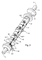
- the measuring transducer and, consequently, a further improvement of the measuring accuracy are provided in that at least one connecting line 601 of the at least temporary current during operation, if appropriate also fixed to the counteroscillator in a suitable manner fixed leads 60, as well as in Fig. 2 shown schematically, is supported on at least one of the two arms 15, 16.
- This may, for example, be a connecting line from a line pair provided for the excitation arrangement, and / or a connecting line from a line pair provided for the sensor arrangement. Further, it is also possible to support both leads of such a pair of wires on one and the same arm.
- the leads 60 can be at least partially combined in pairs, for example, as a "twisted pair" - or as a coaxial cable.
- At least two of the connecting lines are combined to form a line pair, and the at least one line pair on the innermost part, esp. At least one of the boom 15, 16, respectively supported. This can for example be done so that some of the leads are at least partially fixed directly to the boom, while in turn further leads are supported, for example, by means of cable ties. At the same time, however, any of the connection lines held on the arm can also be separate sections are adhesively attached to the boom.
- the leads are guided in accordance with a further embodiment of the invention in such a way on the inner part that along the Gegenschwingers laid and optionally at least selectively fixed thereto line sections 610 "laid along the boom and fixed thereto also line sections 601" 'substantially aligned.
- that measuring tube 10 and counter-oscillator 20 at least temporarily perform coplanar bending vibrations in a common-here of the inertial main axes T1, T2 imaginary spanned - vibration level
- the at least one on Boom-mounted connection line 601 is fixed at least partially outside the common plane of vibration of the measuring tube and counter-oscillator on the boom, esp.
- the at least one on Boom-mounted connection line 601 is fixed at least partially outside the common plane of vibration of the measuring tube and counter-oscillator on the boom, esp.
- first guy point a1 is arranged on the boom supporting the connection line and the second guy point a2 is arranged vis-a-vis on the converter housing.
- portion 601 'extending between the two guying points a1, a2 and the at least one connecting line held on the boom is kept essentially free of tensile stresses; this in particular permanently also in accordance with the operation oscillating inner part and any temperature fluctuations.
- the subsequently laid connection line can also be routed in each case along an inner wall surface of the converter housing 30 and at least selectively fixed thereto.
- the measuring transducer according to the invention is further designed in such a way that all of the connecting lines, which at least temporarily carry current during operation, are supported at least in sections on the same arm.
- the transducer according to the invention can also be designed such that none of the power leads carrying at least temporary electrical current are held on one of the two arms. This in particular even if, as well as in Fig. 2 represented, on the other of the two arms all of the operating at least temporarily electrical current leading leads are supported.
- connection lines proportionally to the first arm and proportionally to the second arm accordingly, so that at least one of the connecting lines is supported on each of the two arms. Therefore, according to another - in Fig. 9 schematically illustrated - variant of the invention provided on the first arm 15 at least a first connection line 601 and the second arm 16 to support at least a second connection line 602. According to one embodiment of this variant of the invention, it is further provided that the two connecting lines 601, 602 are laid in the same way at least along the respectively supporting arm and / or are at least fixed in the same way on the respectively supporting arm. In a further embodiment of the invention, it is further provided that these two connection lines 601, 602 are laid substantially symmetrically to each other.
- each connecting line extends between two bracing points a1, a2, of which the first (a1) is placed on the inner part leading the connecting line and the second (a2) is correspondingly placed on the converter housing 30.
- the two guying points a1, a2 are arranged so that a relative distance A 'therebetween, even when the measuring tube 10 is swinging in the above-mentioned manner, is substantially reduced to reduce the number of connecting lines in the inner part remains unchanged or at most only slightly changed. This can for example be sufficiently given in the region of the coupling zones 11 # and 12 #, but in particular on the arms 15, 16.
- the inner part can be dimensioned such that in operation each of the two arms has at least one rest point, which is also associated with laterally moving Coupling zone remains at least laterally substantially stationary in an associated static rest position, such rest or these immediately surrounding rest region of the arm for fixing of leads are suitable as a position for the first guy point.
- the respective connection line is itself exposed to no or very little mechanical stress due to vibration of the inner part and on the other hand, at least in this area generates no appreciable on the inner part retroactive damping forces.
- the vibrating inner part esp.
- the at least one salaried at the boom at least partially at least part of its resting point or at least is held within an immediately surrounding at least rest area. It is particularly advantageous to place the first guy point on the boom in such a way that it substantially coincides with the at least one rest point.
- the second guy point for this connection line is arranged vis-a-vis the first guy point on the converter housing.
- the transducer can, in addition to the intended for the detection of vibrations of the measuring tube vibration sensors, such as for example, in the EP-A 831 306 , of the US-B 70 40 179 , of the US-A 57 36 653 , of the US-A 53 81 697 or the WO-A 01/02 816 proposed, even more, esp.
- the detection of rather secondary measures, such as temperature, acceleration, strain, stress, etc., serving arranged on the inner part sensors 80 have.
- the accordingly provided connecting lines can then be performed in the same way as, the connecting lines for the sensor and / or the exciter arrangement, optionally combined with these to form a trunk group.
- the transducer has at least one temperature sensor fixed to the counteroscillator and / or at least one strain sensor fixed to the counteroscillator and connecting leads 603 therefor.
- the leads for the temperature sensor and / or the strain sensor at least one, esp. All, is at least partially supported on at least one of the two arms; esp. In the same way as the leads for the exciter and / or the sensor assembly.
- the transducer according to the invention is characterized by a significantly reduced asymmetry in the occurring along the oscillating inner part Dämpfungskraftbelag and is both for measuring tubes with rather smaller nominal sizes DN, esp. In the range of less than 10 mm, as well as in particular for use in piping with a caliber of more than 50 mm and, consequently, also suitable for measuring tubes with nominal widths of much larger than 40 mm.
- DN nominal sizes
Claims (12)
- Transducteur du type vibratoire pour un produit s'écoulant dans une conduite, lequel transducteur comprend :- un tube de mesure (10) vibrant au moins temporairement en fonctionnement, pour l'essentiel droit, destiné à guider le produit, le tube de mesure (10) communiquant avec la conduite par l'intermédiaire d'un élément de tube d'entrée (11), notamment pour l'essentiel droit, débouchant côté entrée, et par l'intermédiaire d'un élément de tube de sortie (12), notamment pour l'essentiel droit, débouchant côté sortie,- un contre-vibrateur (20), notamment pour l'essentiel tubulaire et/ou pour l'essentiel droit, qui est fixé côté entrée sur le tube de mesure en formant une première zone de couplage (11#) et qui est fixé côté sortie sur le tube de mesure (10) en formant une deuxième zone de couplage (12#),- un premier bras (15) couplé côté entrée avec le tube de mesure (10)- un deuxième bras (16) couplé côté sortie avec le tube de mesure (10)- un ensemble capteur (50) fixé au moins partiellement au contre-vibrateur (20), destiné à détecter les vibrations au moins du tube de mesure (10),- un ensemble excitateur (40) fixé au moins partiellement au contre-vibrateur (20), destiné à exciter au moins le tube de mesure (10),- un boîtier de transducteur (30) fixé à l'élément de tube d'entrée (11) et à l'élément de tube de sortie (12), ainsi que- des câbles de raccordement, notamment pour l'ensemble excitateur et/ou pour l'ensemble capteur, câbles de raccordement parmi lesquels au moins un est maintenu au minimum ponctuellement sur une partie intérieure du transducteur, formée par le tube de mesure, le contre-vibrateur et les deux bras, et au minimum ponctuellement sur le boîtier du transducteur,- transducteur pour lequel aussi bien le tube de mesure que le contre-vibrateur exécutent, en fonctionnement, au moins temporairement des vibrations de flexion autour d'un axe de vibration de flexion imaginaire, qui relie de façon imaginaire les deux zones de couplage (11 #, 12#) entre elles,- transducteur pour lequel une partie de l'au moins un câble de raccordement maintenu sur la partie intérieure et le boîtier de transducteur s'étend en oscillation libre entre deux points d'ancrage distants l'un de l'autre, fixant ponctuellement le même câble de raccordement, points d'ancrage parmi lesquels un premier point est disposé sur la partie intérieure du transducteur et un deuxième point sur le boîtier du transducteur,- les deux points d'ancrage étant disposés de telle sorte qu'il reste une distance relative pour l'essentiel inchangée entre eux, y compris lorsque le tube de mesure vibre, et- transducteur pour lequel l'au moins un câble de raccordement maintenu sur les points d'ancrage est acheminé en aval de ces points également le long d'au moins une partie du contre-vibrateur (20) et y est fixé au moins ponctuellement de telle sorte que l'au moins un câble de raccordement maintenu entre les deux points d'ancrage est fixé au moins partiellement, notamment essentiellement sur le contre-vibrateur, le long d'une fibre pour l'essentiel neutre, ne produisant pas de distorsion, du contre-vibrateur lorsque ce dernier exécute des vibrations de flexion.
- Transducteur selon la revendication précédente- pour lequel la partie de l'au moins un câble de raccordement s'étendant entre les deux points d'ancrage est posée pour l'essentiel à pouvoir osciller librement, et/ou- pour lequel la partie de l'au moins un câble de raccordement s'étendant entre les deux points d'ancrage est maintenue pour l'essentiel, notamment durablement, sans contraintes de traction, et/ou- pour lequel au minimum l'au moins un câble de raccordement maintenu sur les deux points d'ancrage est posé en aval des points d'ancrage également le long d'une surface intérieure de paroi du boîtier de convertisseur et y est fixé au moins ponctuellement, et/ou- pour lequel au minimum l'au moins un câble de raccordement maintenu entre les deux points d'ancrage conduit, en fonctionnement, au moins temporairement un courant électrique, et/ou- pour lequel l'ensemble des câbles de raccordement sont fixés au même bras, et/ou- pour lequel l'ensemble des câbles de raccordement sont fixés à l'un des deux bras, et/ou- pour lequel le tube de mesure et le contre-vibrateur oscillent latéralement, en fonctionnement, au moins temporairement et/ou partiellement dans un mode utile, dans lequel ils exécutent des vibrations de flexion pour l'essentiel coplanaires dans un plan de vibrations imaginaire commun, et pour lequel l'au moins un câble de raccordement maintenu sur les deux points d'ancrage est fixé au moins partiellement sur le contre-vibrateur, en dehors du plan de vibrations commun du tube de mesure et du contre-vibrateur.
- Transducteur selon l'une des revendications précédentes- pour lequel le tube de mesure (10) et le contre-vibrateur sont pour l'essentiel droits et alignés l'un par rapport à l'autre essentiellement de façon coaxiale, et/ou- pour lequel le tube de mesure (10) est entouré partiellement par le contre-vibrateur (20), et/ou- pour lequel le tube de mesure (10), l'élément de tube d'entrée (11) et l'élément de tube de sortie (12) sont chacun formés par des segments d'un tube unique, monopièce, et/ou- pour lequel chacun des bras (15, 16) est fixé au moins partiellement directement sur le contre-vibrateur (20), et/ou- pour lequel chacun des bras (15, 16) est formé au moyen d'une douille enfilée sur le contre-vibrateur (20), et/ou- pour lequel chacun des deux bras (15, 16) présente une masse, m15, m16, qui est au moins égale à la masse, m20, du contre-vibrateur (20), et/ou- pour lequel chacun des deux bras (15, 16) présente une masse, m15, m16, qui est inférieure à 5 fois la masse, m20, du contre-vibrateur (20), et/ou- pour lequel le premier bras (15) présente un centre de gravité, M15, situé dans la zone de l'élément de tube d'entrée (11), et pour lequel le deuxième bras (16) présente un centre de gravité, M16, situé dans la zone de l'élément de tube de sortie (12), et/ou- pour lequel l'ensemble excitateur comprend au moins une bobine, notamment couplée de façon rigide avec le contre-vibrateur, ainsi que des fils de raccordement associés, et/ou- pour lequel l'ensemble capteur comprend au moins une bobine, notamment couplée de façon rigide avec le contre-vibrateur, ainsi que des fils de raccordement associés, et/ou- pour lequel chacun des deux bras (15, 16) est constitué pour l'essentiel en forme de tube ou en forme de douille, notamment de telle sorte que chacun des bras présente une épaisseur de paroi maximale, qui est supérieure à l'épaisseur de paroi maximale du contre-vibrateur (20) et/ou de telle sorte que chacun des bras (15, 16) présente une épaisseur de paroi minimale, qui est supérieure à l'épaisseur de paroi maximale du contre-vibrateur (20).
- Transducteur selon la revendication précédente- pour lequel le tube de mesure exécute en fonctionnement au moins temporairement des vibrations torsionnelles autour d'un axe de vibration torsionnelle pour l'essentiel parallèle, notamment coïncidant, avec l'axe de vibration de flexion, et/ou- pour lequel chacun des deux bras exécute en fonctionnement au moins temporairement des vibrations de rotation autour d'un axe de rotation (D15x, D16x) imaginaire, pour l'essentiel perpendiculaire à l'axe de vibration de flexion.
- Transducteur selon la revendication précédente, pour lequel les zones de couplage (11#, 12#) sont déplacés, lorsque le tube de mesure vibre, au moins temporairement latéralement à partir d'une position de repos statique.
- Transducteur selon la revendication précédente, pour lequel chacun des deux bras présente au moins un point de repos ou une zone de repos entourant celui-ci, qui reste dans une position de repos statique correspondante, pour l'essentiel stable, en cas de zones de couplage se déplaçant latéralement, et/ou qui conserve pour l'essentiel une distance relative (A, A') par rapport à une zone du boîtier de transducteur distante à la fois de l'élément de tube d'entrée et de l'élément de tube de sortie.
- Transducteur selon la revendication précédente, pour lequel le premier point d'ancrage est placé sur l'un des bras de telle sorte que l'au moins un câble de raccordement maintenu sur les deux points d'ancrage est fixé sur au moins l'un des deux bras, notamment de telle sorte que l'au moins un câble de raccordement maintenu sur les deux points d'ancrage est maintenu sur le bras au moins partiellement en dehors du plan de vibration commun du tube de mesure et du contre-vibrateur, et/ou de telle sorte que l'au moins un câble de raccordement maintenu sur les deux points d'ancrage est maintenu au moins partiellement à l'intérieur de l'au moins une zone de repos du bras.
- Transducteur selon la revendication précédente,- pour lequel le premier pont d'ancrage situé sur le bras maintenant le câble de raccordement est disposé à l'intérieur de son au moins une zone de repos, notamment de telle sorte que le premier point d'ancrage coïncide avec l'au moins un point de repos, et/ou- pour lequel l'au moins un câble de raccordement maintenu entre les deux points d'ancrage est fixé au moins partiellement par liaison adhésive sur le bras, et/ou- pour lequel le deuxième point d'ancrage pour l'au moins un câble de raccordement maintenu sur le bras est disposé vis-à-vis du premier point d'ancrage sur le boîtier de transducteur.
- Transducteur selon l'une des revendications précédentes, pour lequel au moins l'un des câbles de raccordement est maintenu sur chacun des deux bras.
- Transducteur selon l'une des revendications précédentes 1 à 8, pour lequel aucun câble de raccordement n'est maintenu sur l'un des deux bras.
- Transducteur selon l'une des revendications précédentes, pour lequel l'élément de tube d'entrée (11) et l'élément de tube de sortie (12) sont pour l'essentiel droits et pour lequel l'élément de tube d'entrée (11) et l'élément de tube de sortie (12) sont alignés pour l'essentiel de façon affleurante l'un par rapport à l'autre, ainsi que par rapport à un axe longitudinal (L) du transducteur reliant de façon imaginaire les deux zones de couplage.
- Utilisation d'un transducteur selon l'une des revendications précédentes dans un appareil de mesure en ligne destiné à la mesure et/ou la surveillance d'au moins un paramètre, notamment un débit massique, m, une densité, p, une viscosité, n, d'un produit s'écoulant dans une conduite, notamment un débitmètre massique Coriolis, un densimètre, un viscosimètre, etc.
Applications Claiming Priority (4)
| Application Number | Priority Date | Filing Date | Title |
|---|---|---|---|
| DE200610062185 DE102006062185A1 (de) | 2006-12-22 | 2006-12-22 | Meßwandler vom Vibrationstyp |
| DE200610062219 DE102006062219A1 (de) | 2006-12-22 | 2006-12-22 | Meßwandler vom Vibrationstyp |
| DE200610062220 DE102006062220A1 (de) | 2006-12-22 | 2006-12-22 | Meßwandler vom Vibrationstyp |
| PCT/EP2007/063958 WO2008077818A1 (fr) | 2006-12-22 | 2007-12-14 | Transducteur de mesure du type à vibrations |
Publications (2)
| Publication Number | Publication Date |
|---|---|
| EP2118623A1 EP2118623A1 (fr) | 2009-11-18 |
| EP2118623B1 true EP2118623B1 (fr) | 2016-11-09 |
Family
ID=39313133
Family Applications (3)
| Application Number | Title | Priority Date | Filing Date |
|---|---|---|---|
| EP07848105.8A Active EP2118623B1 (fr) | 2006-12-22 | 2007-12-14 | Transducteur de mesure du type à vibrations |
| EP07857594.1A Active EP2122310B1 (fr) | 2006-12-22 | 2007-12-14 | Transducteur de mesure du type à vibrations |
| EP07857596.6A Active EP2122311B1 (fr) | 2006-12-22 | 2007-12-14 | Transducteur de mesure du type à vibrations |
Family Applications After (2)
| Application Number | Title | Priority Date | Filing Date |
|---|---|---|---|
| EP07857594.1A Active EP2122310B1 (fr) | 2006-12-22 | 2007-12-14 | Transducteur de mesure du type à vibrations |
| EP07857596.6A Active EP2122311B1 (fr) | 2006-12-22 | 2007-12-14 | Transducteur de mesure du type à vibrations |
Country Status (4)
| Country | Link |
|---|---|
| US (3) | US7665370B2 (fr) |
| EP (3) | EP2118623B1 (fr) |
| DK (3) | DK2122311T3 (fr) |
| WO (3) | WO2008077818A1 (fr) |
Families Citing this family (21)
| Publication number | Priority date | Publication date | Assignee | Title |
|---|---|---|---|---|
| DK2122311T3 (en) * | 2006-12-22 | 2017-08-21 | Endress & Hauser Flowtec Ag | VIBRATION TYPE TRANSDUCER |
| DE102008039045A1 (de) * | 2008-08-21 | 2010-02-25 | Endress + Hauser Flowtec Ag | Sensor in mikromechanischer Bauweise |
| DE102008044186A1 (de) | 2008-11-28 | 2010-06-02 | Endress + Hauser Flowtec Ag | Magneteinrichtung sowie Meßaufnehmer vom Vibrationstyp mit einer solchen Magneteinrichtung |
| DE102013114731A1 (de) | 2013-12-20 | 2015-06-25 | Endress+Hauser Flowtec Ag | Spule |
| CN105849510B (zh) | 2013-12-20 | 2020-12-15 | 恩德斯+豪斯流量技术股份有限公司 | 线圈 |
| CN104075936B (zh) * | 2014-07-08 | 2016-06-22 | 天津大学 | 无约束管段横向运动全过程监控测试系统 |
| DE102015104931A1 (de) * | 2014-12-31 | 2016-06-30 | Endress + Hauser Flowtec Ag | Coriolis-Massedurchfussmessgerät mit vier gebogenen Messrohren |
| DE102016104551A1 (de) | 2016-03-11 | 2017-09-14 | Krohne Ag | Verfahren zur Ausstattung eines Coriolis-Massedurchflussmessgeräts mit elektrischen Verbindungen |
| CN105699287A (zh) * | 2016-03-15 | 2016-06-22 | 天津大学 | 无约束管段轴向循环加载测试系统 |
| CN105823687B (zh) * | 2016-05-07 | 2018-08-31 | 天津大学 | 一种去除端部土体影响的海底管道侧向屈曲实验装置 |
| CN109564410B (zh) * | 2016-06-10 | 2022-06-21 | Abb瑞士股份有限公司 | 用于识别机械负载的物理参数的半自动、交互式工具 |
| DE102017121157A1 (de) | 2017-08-09 | 2019-02-14 | Endress+Hauser Flowtec Ag | Spule sowie Meßwandler mit einer solchen Spule |
| DE102017131199A1 (de) | 2017-12-22 | 2019-06-27 | Endress + Hauser Flowtec Ag | Coriolis-Massendurchfluß-Meßgerät |
| CN113242960A (zh) | 2018-12-20 | 2021-08-10 | 恩德斯+豪斯流量技术股份有限公司 | 科里奥利质量流量计 |
| US20220099543A1 (en) | 2018-12-20 | 2022-03-31 | Endress+Hauser Flowtec Ag | Coriolis mass flow meter |
| DE102018133117A1 (de) | 2018-12-20 | 2020-06-25 | Endress+Hauser Flowtec Ag | Coriolis-Massendurchfluß-Meßgerät |
| WO2020126286A1 (fr) | 2018-12-21 | 2020-06-25 | Endress+Hauser Flowtec Ag | Débitmètre massique à effet coriolis muni d'un détecteur de champ magnétique |
| DE102019133610A1 (de) | 2019-12-09 | 2021-06-10 | Endress + Hauser Flowtec Ag | Vibronisches Meßsystem zum Messen eines Massestroms eines fluiden Meßstoff |
| DE102020127382A1 (de) | 2020-10-16 | 2022-04-21 | Endress+Hauser Flowtec Ag | Verfahren zum Überprüfen eines vibronischen Meßsystems |
| DE102022112523A1 (de) | 2022-05-18 | 2023-11-23 | Endress+Hauser Flowtec Ag | Vibronisches Meßsystem |
| DE102022116111A1 (de) | 2022-06-28 | 2023-12-28 | Endress+Hauser Flowtec Ag | Vibronisches Meßsystem |
Family Cites Families (20)
| Publication number | Priority date | Publication date | Assignee | Title |
|---|---|---|---|---|
| EP0553939B1 (fr) * | 1985-08-29 | 1996-06-19 | Micro Motion Incorporated | Débitmètre à effet Coriolis |
| US4955239A (en) * | 1986-05-22 | 1990-09-11 | Micro Motion, Inc. | Apparatus for electrically interconnecting vibrating structures |
| US5987999A (en) * | 1998-07-01 | 1999-11-23 | Micro Motion, Inc. | Sensitivity enhancing balance bar |
| US6227059B1 (en) * | 1999-01-12 | 2001-05-08 | Direct Measurement Corporation | System and method for employing an imaginary difference signal component to compensate for boundary condition effects on a Coriolis mass flow meter |
| US6684716B2 (en) * | 2000-04-07 | 2004-02-03 | Kazumasa Ohnishi | Coriolis flowmeter |
| US6487917B1 (en) * | 2000-05-02 | 2002-12-03 | Micro Motion, Inc. | Low thermal stress balance bar for a coriolis flowmeter |
| US6634241B1 (en) * | 2000-09-22 | 2003-10-21 | Micro Motion, Inc. | Method and apparatus for bonding a connecting ring to a flow tube and balance bar of a coriolis flowmeter |
| EP1253408A1 (fr) * | 2001-04-24 | 2002-10-30 | Endress + Hauser Flowtec AG | Transducteur de mesure du type vibrant |
| US6691583B2 (en) * | 2001-04-24 | 2004-02-17 | Endress + Hauser Flowtec Ag | Vibratory transducer |
| EP1502084B1 (fr) * | 2002-05-08 | 2020-01-15 | Endress + Hauser Flowtec AG | Amortisseur d'oscillations de torsion pour transformateur de mesure de type vibrant |
| DE10235322A1 (de) * | 2002-08-01 | 2004-02-12 | Endress + Hauser Flowtec Ag, Reinach | Meßwandler vom Vibrationstyp |
| US7040179B2 (en) * | 2002-12-06 | 2006-05-09 | Endress+ Hauser Flowtec Ag | Process meter |
| US7051598B2 (en) * | 2003-03-21 | 2006-05-30 | Endress + Hauser Flowtec Ag | Magnetic circuit arrangement for a sensor |
| US7040181B2 (en) * | 2004-03-19 | 2006-05-09 | Endress + Hauser Flowtec Ag | Coriolis mass measuring device |
| US7077014B2 (en) * | 2004-06-23 | 2006-07-18 | Endress + Hauser Flowtec Ag | Vibration-type measuring transducer |
| US7412903B2 (en) * | 2005-05-18 | 2008-08-19 | Endress + Hauser Flowtec Ag | In-line measuring devices and method for compensation measurement errors in in-line measuring devices |
| US7475603B2 (en) * | 2005-11-15 | 2009-01-13 | Endress + Hauser Flowtec Ag | Measurement transducer of vibration-type |
| US7490521B2 (en) * | 2005-11-15 | 2009-02-17 | Endress + Hauser Flowtec Ag | Measurement transducer of vibration type |
| US7472607B2 (en) * | 2005-11-15 | 2009-01-06 | Endress + Hauser Flowtec Ag | Measurement transducer of vibration type |
| DK2122311T3 (en) * | 2006-12-22 | 2017-08-21 | Endress & Hauser Flowtec Ag | VIBRATION TYPE TRANSDUCER |
-
2007
- 2007-12-14 DK DK07857596.6T patent/DK2122311T3/en active
- 2007-12-14 DK DK07848105.8T patent/DK2118623T3/en active
- 2007-12-14 DK DK07857594.1T patent/DK2122310T3/en active
- 2007-12-14 WO PCT/EP2007/063958 patent/WO2008077818A1/fr active Application Filing
- 2007-12-14 EP EP07848105.8A patent/EP2118623B1/fr active Active
- 2007-12-14 WO PCT/EP2007/063957 patent/WO2008077817A1/fr active Application Filing
- 2007-12-14 EP EP07857594.1A patent/EP2122310B1/fr active Active
- 2007-12-14 WO PCT/EP2007/063960 patent/WO2008077819A1/fr active Application Filing
- 2007-12-14 EP EP07857596.6A patent/EP2122311B1/fr active Active
- 2007-12-19 US US12/000,934 patent/US7665370B2/en active Active
- 2007-12-20 US US12/003,105 patent/US7658116B2/en active Active
- 2007-12-21 US US12/003,265 patent/US7654152B2/en active Active
Also Published As
| Publication number | Publication date |
|---|---|
| EP2122310B1 (fr) | 2016-03-23 |
| US20080223149A1 (en) | 2008-09-18 |
| DK2122310T3 (en) | 2016-07-04 |
| WO2008077817A1 (fr) | 2008-07-03 |
| DK2122311T3 (en) | 2017-08-21 |
| US20080250871A1 (en) | 2008-10-16 |
| EP2118623A1 (fr) | 2009-11-18 |
| US7654152B2 (en) | 2010-02-02 |
| EP2122310A1 (fr) | 2009-11-25 |
| EP2122311B1 (fr) | 2017-04-26 |
| US7658116B2 (en) | 2010-02-09 |
| WO2008077819A1 (fr) | 2008-07-03 |
| EP2122311A1 (fr) | 2009-11-25 |
| US20080223150A1 (en) | 2008-09-18 |
| US7665370B2 (en) | 2010-02-23 |
| WO2008077818A1 (fr) | 2008-07-03 |
| DK2118623T3 (en) | 2017-01-30 |
Similar Documents
| Publication | Publication Date | Title |
|---|---|---|
| EP2118623B1 (fr) | Transducteur de mesure du type à vibrations | |
| EP1759178B1 (fr) | Transducteur du type transducteur de vibrations | |
| EP1502085B1 (fr) | Transformateur de mesure de type a vibrations | |
| EP1381830B1 (fr) | Transducteur de mesure de type vibratoire | |
| EP1381831B1 (fr) | Capteur de débit du type vibrant | |
| EP2406592B1 (fr) | Système de mesure comprenant un transducteur du type vibrant | |
| EP2406589B1 (fr) | Système de mesure pour des fluides s'écoulant dans une canalisation | |
| DE102007062397A1 (de) | Meßwandler vom Vibrationstyp | |
| EP3084367B1 (fr) | Bobine | |
| EP2516972A1 (fr) | Capteur de mesure du type à vibrations | |
| WO2000014485A1 (fr) | Appareil de mesure de debit massique a effet de coriolis avec cylindre de compensation | |
| EP1345013A1 (fr) | Débitmètre massique de Coriolis utilisant un mélangeur à tourbillon | |
| DE102009055069A1 (de) | Meßaufnehmer vom Vibrationstyp | |
| EP2201337B1 (fr) | Transducteur de vibrations | |
| WO2019029941A1 (fr) | Bobine et convertisseur de mesure doté d'une telle bobine | |
| EP1949048B1 (fr) | Convertisseur de mesure du type a vibrations | |
| DE10235322A1 (de) | Meßwandler vom Vibrationstyp | |
| DE102006062185A1 (de) | Meßwandler vom Vibrationstyp | |
| DE102006062219A1 (de) | Meßwandler vom Vibrationstyp | |
| DE102006062220A1 (de) | Meßwandler vom Vibrationstyp | |
| WO2004083785A2 (fr) | Ensemble circuit magnetique pour un capteur de mesure | |
| DE102013114731A1 (de) | Spule |
Legal Events
| Date | Code | Title | Description |
|---|---|---|---|
| PUAI | Public reference made under article 153(3) epc to a published international application that has entered the european phase |
Free format text: ORIGINAL CODE: 0009012 |
|
| 17P | Request for examination filed |
Effective date: 20090905 |
|
| AK | Designated contracting states |
Kind code of ref document: A1 Designated state(s): AT BE BG CH CY CZ DE DK EE ES FI FR GB GR HU IE IS IT LI LT LU LV MC MT NL PL PT RO SE SI SK TR |
|
| RIN1 | Information on inventor provided before grant (corrected) |
Inventor name: FUCHS, MICHAEL Inventor name: WIESMANN, MICHAEL Inventor name: PROBST, LEONHARD Inventor name: RIEDER, ALFRED |
|
| DAX | Request for extension of the european patent (deleted) | ||
| 17Q | First examination report despatched |
Effective date: 20110810 |
|
| GRAP | Despatch of communication of intention to grant a patent |
Free format text: ORIGINAL CODE: EPIDOSNIGR1 |
|
| INTG | Intention to grant announced |
Effective date: 20160624 |
|
| GRAS | Grant fee paid |
Free format text: ORIGINAL CODE: EPIDOSNIGR3 |
|
| GRAA | (expected) grant |
Free format text: ORIGINAL CODE: 0009210 |
|
| AK | Designated contracting states |
Kind code of ref document: B1 Designated state(s): AT BE BG CH CY CZ DE DK EE ES FI FR GB GR HU IE IS IT LI LT LU LV MC MT NL PL PT RO SE SI SK TR |
|
| REG | Reference to a national code |
Ref country code: GB Ref legal event code: FG4D Free format text: NOT ENGLISH |
|
| REG | Reference to a national code |
Ref country code: AT Ref legal event code: REF Ref document number: 844373 Country of ref document: AT Kind code of ref document: T Effective date: 20161115 Ref country code: CH Ref legal event code: EP |
|
| REG | Reference to a national code |
Ref country code: IE Ref legal event code: FG4D Free format text: LANGUAGE OF EP DOCUMENT: GERMAN |
|
| REG | Reference to a national code |
Ref country code: NL Ref legal event code: FP |
|
| REG | Reference to a national code |
Ref country code: DE Ref legal event code: R096 Ref document number: 502007015254 Country of ref document: DE Ref country code: FR Ref legal event code: PLFP Year of fee payment: 10 |
|
| REG | Reference to a national code |
Ref country code: DK Ref legal event code: T3 Effective date: 20170126 |
|
| PG25 | Lapsed in a contracting state [announced via postgrant information from national office to epo] |
Ref country code: LV Free format text: LAPSE BECAUSE OF FAILURE TO SUBMIT A TRANSLATION OF THE DESCRIPTION OR TO PAY THE FEE WITHIN THE PRESCRIBED TIME-LIMIT Effective date: 20161109 |
|
| REG | Reference to a national code |
Ref country code: LT Ref legal event code: MG4D |
|
| PG25 | Lapsed in a contracting state [announced via postgrant information from national office to epo] |
Ref country code: SE Free format text: LAPSE BECAUSE OF FAILURE TO SUBMIT A TRANSLATION OF THE DESCRIPTION OR TO PAY THE FEE WITHIN THE PRESCRIBED TIME-LIMIT Effective date: 20161109 Ref country code: GR Free format text: LAPSE BECAUSE OF FAILURE TO SUBMIT A TRANSLATION OF THE DESCRIPTION OR TO PAY THE FEE WITHIN THE PRESCRIBED TIME-LIMIT Effective date: 20170210 Ref country code: LT Free format text: LAPSE BECAUSE OF FAILURE TO SUBMIT A TRANSLATION OF THE DESCRIPTION OR TO PAY THE FEE WITHIN THE PRESCRIBED TIME-LIMIT Effective date: 20161109 |
|
| PG25 | Lapsed in a contracting state [announced via postgrant information from national office to epo] |
Ref country code: FI Free format text: LAPSE BECAUSE OF FAILURE TO SUBMIT A TRANSLATION OF THE DESCRIPTION OR TO PAY THE FEE WITHIN THE PRESCRIBED TIME-LIMIT Effective date: 20161109 Ref country code: ES Free format text: LAPSE BECAUSE OF FAILURE TO SUBMIT A TRANSLATION OF THE DESCRIPTION OR TO PAY THE FEE WITHIN THE PRESCRIBED TIME-LIMIT Effective date: 20161109 Ref country code: PT Free format text: LAPSE BECAUSE OF FAILURE TO SUBMIT A TRANSLATION OF THE DESCRIPTION OR TO PAY THE FEE WITHIN THE PRESCRIBED TIME-LIMIT Effective date: 20170309 Ref country code: PL Free format text: LAPSE BECAUSE OF FAILURE TO SUBMIT A TRANSLATION OF THE DESCRIPTION OR TO PAY THE FEE WITHIN THE PRESCRIBED TIME-LIMIT Effective date: 20161109 Ref country code: BE Free format text: LAPSE BECAUSE OF NON-PAYMENT OF DUE FEES Effective date: 20161231 Ref country code: IS Free format text: LAPSE BECAUSE OF FAILURE TO SUBMIT A TRANSLATION OF THE DESCRIPTION OR TO PAY THE FEE WITHIN THE PRESCRIBED TIME-LIMIT Effective date: 20170309 |
|
| PG25 | Lapsed in a contracting state [announced via postgrant information from national office to epo] |
Ref country code: EE Free format text: LAPSE BECAUSE OF FAILURE TO SUBMIT A TRANSLATION OF THE DESCRIPTION OR TO PAY THE FEE WITHIN THE PRESCRIBED TIME-LIMIT Effective date: 20161109 Ref country code: CZ Free format text: LAPSE BECAUSE OF FAILURE TO SUBMIT A TRANSLATION OF THE DESCRIPTION OR TO PAY THE FEE WITHIN THE PRESCRIBED TIME-LIMIT Effective date: 20161109 Ref country code: RO Free format text: LAPSE BECAUSE OF FAILURE TO SUBMIT A TRANSLATION OF THE DESCRIPTION OR TO PAY THE FEE WITHIN THE PRESCRIBED TIME-LIMIT Effective date: 20161109 Ref country code: SK Free format text: LAPSE BECAUSE OF FAILURE TO SUBMIT A TRANSLATION OF THE DESCRIPTION OR TO PAY THE FEE WITHIN THE PRESCRIBED TIME-LIMIT Effective date: 20161109 |
|
| REG | Reference to a national code |
Ref country code: CH Ref legal event code: PL |
|
| REG | Reference to a national code |
Ref country code: DE Ref legal event code: R097 Ref document number: 502007015254 Country of ref document: DE |
|
| PG25 | Lapsed in a contracting state [announced via postgrant information from national office to epo] |
Ref country code: BG Free format text: LAPSE BECAUSE OF FAILURE TO SUBMIT A TRANSLATION OF THE DESCRIPTION OR TO PAY THE FEE WITHIN THE PRESCRIBED TIME-LIMIT Effective date: 20170209 |
|
| PLBE | No opposition filed within time limit |
Free format text: ORIGINAL CODE: 0009261 |
|
| STAA | Information on the status of an ep patent application or granted ep patent |
Free format text: STATUS: NO OPPOSITION FILED WITHIN TIME LIMIT |
|
| PG25 | Lapsed in a contracting state [announced via postgrant information from national office to epo] |
Ref country code: MC Free format text: LAPSE BECAUSE OF FAILURE TO SUBMIT A TRANSLATION OF THE DESCRIPTION OR TO PAY THE FEE WITHIN THE PRESCRIBED TIME-LIMIT Effective date: 20161109 |
|
| REG | Reference to a national code |
Ref country code: IE Ref legal event code: MM4A |
|
| 26N | No opposition filed |
Effective date: 20170810 |
|
| PG25 | Lapsed in a contracting state [announced via postgrant information from national office to epo] |
Ref country code: CH Free format text: LAPSE BECAUSE OF NON-PAYMENT OF DUE FEES Effective date: 20161231 Ref country code: LU Free format text: LAPSE BECAUSE OF NON-PAYMENT OF DUE FEES Effective date: 20161214 Ref country code: LI Free format text: LAPSE BECAUSE OF NON-PAYMENT OF DUE FEES Effective date: 20161231 |
|
| PG25 | Lapsed in a contracting state [announced via postgrant information from national office to epo] |
Ref country code: IE Free format text: LAPSE BECAUSE OF NON-PAYMENT OF DUE FEES Effective date: 20161214 Ref country code: SI Free format text: LAPSE BECAUSE OF FAILURE TO SUBMIT A TRANSLATION OF THE DESCRIPTION OR TO PAY THE FEE WITHIN THE PRESCRIBED TIME-LIMIT Effective date: 20161109 |
|
| REG | Reference to a national code |
Ref country code: FR Ref legal event code: PLFP Year of fee payment: 11 |
|
| REG | Reference to a national code |
Ref country code: BE Ref legal event code: MM Effective date: 20161231 |
|
| REG | Reference to a national code |
Ref country code: AT Ref legal event code: MM01 Ref document number: 844373 Country of ref document: AT Kind code of ref document: T Effective date: 20161214 |
|
| PG25 | Lapsed in a contracting state [announced via postgrant information from national office to epo] |
Ref country code: AT Free format text: LAPSE BECAUSE OF NON-PAYMENT OF DUE FEES Effective date: 20161214 Ref country code: CY Free format text: LAPSE BECAUSE OF FAILURE TO SUBMIT A TRANSLATION OF THE DESCRIPTION OR TO PAY THE FEE WITHIN THE PRESCRIBED TIME-LIMIT Effective date: 20161109 Ref country code: HU Free format text: LAPSE BECAUSE OF FAILURE TO SUBMIT A TRANSLATION OF THE DESCRIPTION OR TO PAY THE FEE WITHIN THE PRESCRIBED TIME-LIMIT; INVALID AB INITIO Effective date: 20071214 |
|
| PG25 | Lapsed in a contracting state [announced via postgrant information from national office to epo] |
Ref country code: TR Free format text: LAPSE BECAUSE OF FAILURE TO SUBMIT A TRANSLATION OF THE DESCRIPTION OR TO PAY THE FEE WITHIN THE PRESCRIBED TIME-LIMIT Effective date: 20161109 |
|
| PG25 | Lapsed in a contracting state [announced via postgrant information from national office to epo] |
Ref country code: MT Free format text: LAPSE BECAUSE OF FAILURE TO SUBMIT A TRANSLATION OF THE DESCRIPTION OR TO PAY THE FEE WITHIN THE PRESCRIBED TIME-LIMIT Effective date: 20161109 |
|
| PGFP | Annual fee paid to national office [announced via postgrant information from national office to epo] |
Ref country code: DK Payment date: 20191227 Year of fee payment: 13 Ref country code: FR Payment date: 20191220 Year of fee payment: 13 |
|
| PGFP | Annual fee paid to national office [announced via postgrant information from national office to epo] |
Ref country code: IT Payment date: 20201224 Year of fee payment: 14 |
|
| REG | Reference to a national code |
Ref country code: DK Ref legal event code: EBP Effective date: 20201231 |
|
| PG25 | Lapsed in a contracting state [announced via postgrant information from national office to epo] |
Ref country code: FR Free format text: LAPSE BECAUSE OF NON-PAYMENT OF DUE FEES Effective date: 20201231 |
|
| PG25 | Lapsed in a contracting state [announced via postgrant information from national office to epo] |
Ref country code: DK Free format text: LAPSE BECAUSE OF NON-PAYMENT OF DUE FEES Effective date: 20201231 |
|
| PGFP | Annual fee paid to national office [announced via postgrant information from national office to epo] |
Ref country code: NL Payment date: 20211221 Year of fee payment: 15 |
|
| PG25 | Lapsed in a contracting state [announced via postgrant information from national office to epo] |
Ref country code: IT Free format text: LAPSE BECAUSE OF NON-PAYMENT OF DUE FEES Effective date: 20211214 |
|
| P01 | Opt-out of the competence of the unified patent court (upc) registered |
Effective date: 20230601 |
|
| REG | Reference to a national code |
Ref country code: NL Ref legal event code: MM Effective date: 20230101 |
|
| PG25 | Lapsed in a contracting state [announced via postgrant information from national office to epo] |
Ref country code: NL Free format text: LAPSE BECAUSE OF NON-PAYMENT OF DUE FEES Effective date: 20230101 |
|
| PGFP | Annual fee paid to national office [announced via postgrant information from national office to epo] |
Ref country code: GB Payment date: 20231220 Year of fee payment: 17 |
|
| PGFP | Annual fee paid to national office [announced via postgrant information from national office to epo] |
Ref country code: DE Payment date: 20231214 Year of fee payment: 17 |