EP2118489B1 - Cartridge -type single-screw pump and dye-meter equipped with such pump - Google Patents
Cartridge -type single-screw pump and dye-meter equipped with such pump Download PDFInfo
- Publication number
- EP2118489B1 EP2118489B1 EP07736656.5A EP07736656A EP2118489B1 EP 2118489 B1 EP2118489 B1 EP 2118489B1 EP 07736656 A EP07736656 A EP 07736656A EP 2118489 B1 EP2118489 B1 EP 2118489B1
- Authority
- EP
- European Patent Office
- Prior art keywords
- pump
- cartridge
- dye
- fluidic tube
- outlet
- Prior art date
- Legal status (The legal status is an assumption and is not a legal conclusion. Google has not performed a legal analysis and makes no representation as to the accuracy of the status listed.)
- Active
Links
Images

Classifications
-
- F—MECHANICAL ENGINEERING; LIGHTING; HEATING; WEAPONS; BLASTING
- F04—POSITIVE - DISPLACEMENT MACHINES FOR LIQUIDS; PUMPS FOR LIQUIDS OR ELASTIC FLUIDS
- F04C—ROTARY-PISTON, OR OSCILLATING-PISTON, POSITIVE-DISPLACEMENT MACHINES FOR LIQUIDS; ROTARY-PISTON, OR OSCILLATING-PISTON, POSITIVE-DISPLACEMENT PUMPS
- F04C2/00—Rotary-piston machines or pumps
- F04C2/08—Rotary-piston machines or pumps of intermeshing-engagement type, i.e. with engagement of co-operating members similar to that of toothed gearing
- F04C2/10—Rotary-piston machines or pumps of intermeshing-engagement type, i.e. with engagement of co-operating members similar to that of toothed gearing of internal-axis type with the outer member having more teeth or tooth-equivalents, e.g. rollers, than the inner member
- F04C2/107—Rotary-piston machines or pumps of intermeshing-engagement type, i.e. with engagement of co-operating members similar to that of toothed gearing of internal-axis type with the outer member having more teeth or tooth-equivalents, e.g. rollers, than the inner member with helical teeth
- F04C2/1071—Rotary-piston machines or pumps of intermeshing-engagement type, i.e. with engagement of co-operating members similar to that of toothed gearing of internal-axis type with the outer member having more teeth or tooth-equivalents, e.g. rollers, than the inner member with helical teeth the inner and outer member having a different number of threads and one of the two being made of elastic materials, e.g. Moineau type
- F04C2/1073—Rotary-piston machines or pumps of intermeshing-engagement type, i.e. with engagement of co-operating members similar to that of toothed gearing of internal-axis type with the outer member having more teeth or tooth-equivalents, e.g. rollers, than the inner member with helical teeth the inner and outer member having a different number of threads and one of the two being made of elastic materials, e.g. Moineau type where one member is stationary while the other member rotates and orbits
- F04C2/1075—Construction of the stationary member
-
- B—PERFORMING OPERATIONS; TRANSPORTING
- B01—PHYSICAL OR CHEMICAL PROCESSES OR APPARATUS IN GENERAL
- B01F—MIXING, e.g. DISSOLVING, EMULSIFYING OR DISPERSING
- B01F33/00—Other mixers; Mixing plants; Combinations of mixers
- B01F33/80—Mixing plants; Combinations of mixers
- B01F33/84—Mixing plants with mixing receptacles receiving material dispensed from several component receptacles, e.g. paint tins
-
- F—MECHANICAL ENGINEERING; LIGHTING; HEATING; WEAPONS; BLASTING
- F04—POSITIVE - DISPLACEMENT MACHINES FOR LIQUIDS; PUMPS FOR LIQUIDS OR ELASTIC FLUIDS
- F04C—ROTARY-PISTON, OR OSCILLATING-PISTON, POSITIVE-DISPLACEMENT MACHINES FOR LIQUIDS; ROTARY-PISTON, OR OSCILLATING-PISTON, POSITIVE-DISPLACEMENT PUMPS
- F04C13/00—Adaptations of machines or pumps for special use, e.g. for extremely high pressures
- F04C13/001—Pumps for particular liquids
-
- F—MECHANICAL ENGINEERING; LIGHTING; HEATING; WEAPONS; BLASTING
- F04—POSITIVE - DISPLACEMENT MACHINES FOR LIQUIDS; PUMPS FOR LIQUIDS OR ELASTIC FLUIDS
- F04C—ROTARY-PISTON, OR OSCILLATING-PISTON, POSITIVE-DISPLACEMENT MACHINES FOR LIQUIDS; ROTARY-PISTON, OR OSCILLATING-PISTON, POSITIVE-DISPLACEMENT PUMPS
- F04C2240/00—Components
- F04C2240/70—Use of multiplicity of similar components; Modular construction
Definitions
- the present invention refers to a cartridge-type single-screw pump, in particular for dye-meters.
- the present invention further refers to a dye-meter equipped with such cartridge-type single-screw pump.
- dye-meters are batching machines for preparing colouring composites, such as paints, enamels, paintings, typically comprising a plurality of storage tanks for individual components and batching and delivering devices of such components adapted to take from individual tanks accurate amounts of a component, depending on desired compositions, in order to come to the desired final compound.
- the prior art has two families of dye-meters: those with tanks in a fixed position connected through ducts to a delivering head placed above a vessel for the final compound, in which the delivery of individual components can simultaneously occur, and those in which the tanks are placed on rotary platforms equipped with a kinematism adapted to place in turn the individual tanks, or individual sub-groups of tanks, on the vessel of the final compound to allow delivering the component.
- EP-A-1 308 624 discloses a single-screw pump according to the preamble of Claim 1.
- object of the present invention is solving the above prior art problems by providing a cartridge-type single-screw pump, to be used in particular as a batching and delivering device in a dye-meter, substantially composed of an external fixed pump body within which a removable pumping cartridge is inserted, that can be easily, quickly and economically replaced in case of maintenance, breakage or malfunction, thereby avoiding the long and costly ordinary maintenance of the pump as a whole.
- an object of the present invention is providing a dye-meter equipped with at least one batching and delivering device realised as a cartridge-type single-screw pump according to the present invention.
- the cartridge-type single-screw pump according to the present invention is adapted to volumetrically batch a certain amount of a fluid, for example a colouring component, preferably contained inside storage means and to deliver it towards suitable distributing means, such as for example a nozzle or a delivering head like those known in the art.
- suitable distributing means such as for example a nozzle or a delivering head like those known in the art.
- the cartridge-type single-screw pump 1 is composed of an external fixed pump body 10 and a removable pumping cartridge 20, this latter one being adapted to be inserted in at least one insertion seat 11 of the external fixed pump body 10 and to operatively cooperate with this latter one.
- the external fixed pump body 10 comprises a first inlet fluidic duct 12 and a second outlet fluidic duct 13, such first and second ducts respectively 12 and 13 communicating with the interior of the insertion seat 11.
- the first inlet fluidic duct 12 is particularly adapted to be connected, by interposing circuit fluidic connection means (not shown and preferably made as at least one duct), to fluid storage means (such fluid being preferably a dye) to be batched and delivered.
- the first inlet fluidic duct 12 can further be equipped with at least one adjusting valve 15 for the fluid flow-rate that crosses it.
- the second outlet fluidic duct 13 instead is particularly adapted to be connected to the fluid distributing means by interposing other circuit fluidic connection means (not shown).
- the external fixed pump body 10 can be equipped with suitable securing means to a machinery, such as for example a dye-meter, to be served: for example, the securing means can be made as at least one bracket 14 to be fixed to the machinery through screws or bolts.
- the removable pumping cartridge 20 is in particular a pump with progressive recesses (device usually employed for pumping extremely viscous substances, such as for example concretes) comprising an external housing 21 containing a pump stator 22 inside which an internal rotor 23 can rotate under the action of at least one driving motor 24 connected therewith (in particular, the drive shaft 24a of the driving motor 24 is preferably connected to the internal rotor 23 in such a way as to be coaxial with the rotation axis of the internal rotor 23 itself).
- the internal rotor 23 is shaped as a worm screw with progressive recesses whose relative rotation with respect to the stator 22 causes a translation movement of the fluid present inside it.
- the external housing 21 is equipped with a first inlet opening 25 adapted to correspond with the first inlet fluidic duct 12 and to communicate the first inlet fluidic duct 12 with the interior of the stator 22 when the removable pumping cartridge 20 is inserted inside the insertion seat 11 of the external fixed pump body 10.
- the external housing 21 is equipped with a second outlet opening 26 adapted to correspond with the second outlet fluidic duct 13 and to communicate the stator 22 interior with the second outlet fluidic duct 13 itself when the removable pumping cartridge 20 is inserted inside the insertion seat 11 of the external fixed pump body 10.
- the second outlet opening 26 is realised as an attachment nipple equipped with related sealing means 26a adapted to be inserted and tightly coupled inside the second outlet fluidic duct 13.
- the pump with progressive recesses of the removable pumping cartridge 20 When actuated by the driving motor 24, the pump with progressive recesses of the removable pumping cartridge 20, during the rotation movement of its internal rotor 23, transfers certain amounts of fluid, entering inside the stator 22 through the first inlet fluidic duct 12 and the first inlet opening 25, towards and through the second outlet opening 26 and the second outlet fluidic duct 13.
- the external housing 21 can be equipped with securing means to the insertion seat 11; preferably, as shown in the Figures, the securing means can be made as a first flange 28 integral with the removable pumping cartridge 20, adapted to be coupled with a respective second flange 18 integral with the external fixed pump body 10, such first and second flanges respectively 28 and 18 adapted to be mutually connected through adequate connection means, such as for example screws or bolts 29.
- the cartridge-type single-screw pump 1 allows obtaining the same results by simply and quickly withdrawing the removable pumping cartridge 20 from the external fixed pump body 10 and replacing it with another new removable pumping cartridge 20.
- the present invention further refers to a dye-meter equipped with at least one cartridge-type single-screw pump 1 according to the present invention and as previously described.
- a dye-meter 100 according to the present invention comprises a supporting structure 101, that obviously can be equipped with removable coating panels 102 in order to protect the pump 1 from external agents containing at least one cartridge-type single-screw pump 1, whose first inlet fluidic duct 12 is connected through circuit fluidic connection means (not shown) to storage means (preferably made as at least one tank 103) of a colouring component and whose second outlet fluidic duct 13 is connected through other circuit fluidic connection means (not shown) to the distributing means (not shown) of the colouring component itself, under which a vessel (not shown) can be arranged, adapted to collect the final colouring compound.
- the dye-meter 100 can also comprise managing means that, in particular, by operating on the driving motor 24 of each pump 1, check the correct batching and delivery of individual colouring components to obtain the final colouring compound depending on a certain composition formula.
- the managing means of the dye-meter 100 can be those substantially known for managing and driving traditional dye-meters; in particular, the managing means can comprise a known PC through which the pump 1 operation can be managed and, among other things, formulations of final colouring compounds can be inserted, amended and/or modified.
- the number and arrangement of the above components, and in particular of the cartridge-type single-screw pumps 1 according to the present invention, can be different, and particularly depending on the variety of colouring compounds that the dye-meter 100 according to the present invention must be able to produce.
Landscapes
- Engineering & Computer Science (AREA)
- Mechanical Engineering (AREA)
- General Engineering & Computer Science (AREA)
- Chemical & Material Sciences (AREA)
- Chemical Kinetics & Catalysis (AREA)
- Details And Applications Of Rotary Liquid Pumps (AREA)
- Rotary Pumps (AREA)
Description
- The present invention refers to a cartridge-type single-screw pump, in particular for dye-meters. The present invention further refers to a dye-meter equipped with such cartridge-type single-screw pump.
- As known, dye-meters are batching machines for preparing colouring composites, such as paints, enamels, paintings, typically comprising a plurality of storage tanks for individual components and batching and delivering devices of such components adapted to take from individual tanks accurate amounts of a component, depending on desired compositions, in order to come to the desired final compound. In general terms, the prior art has two families of dye-meters: those with tanks in a fixed position connected through ducts to a delivering head placed above a vessel for the final compound, in which the delivery of individual components can simultaneously occur, and those in which the tanks are placed on rotary platforms equipped with a kinematism adapted to place in turn the individual tanks, or individual sub-groups of tanks, on the vessel of the final compound to allow delivering the component.
- Moreover, depending on the components batching mode, there are dye-meters with weight batching, typically more accurate but relatively slow since they require weighing in succession all components to be batched, and volumetric dye-meters, so far less accurate than the previous ones, but quicker in preparing the final composites. Moreover, in Patent Application n.
WO2006/106540 , a volumetric dye-meter is disclosed, equipped, among others, with batching and delivering devices realised as pumps with progressive recesses. - All existing dye-meters however have numerous inconveniences: first of all, given their construction complexity, prior art dye-meters are unavoidably affected by problems related to their reliability in time. In particular, in case of malfunction or breakage of dye batching and delivering devices, a machine stop is unavoidable, which is typically long (generally on the order of 3-5 days for finding spare parts and for specialised assistance interventions), with related discomforts both from the productive, and from the economic points of view. Similarly, the same ordinary maintenance of batching and delivering devices can generate machine stop times of the whole dye-meter that create economic losses and non-neglectable inconveniences.
-
EP-A-1 308 624 discloses a single-screw pump according to the preamble ofClaim 1. - Therefore, object of the present invention is solving the above prior art problems by providing a cartridge-type single-screw pump, to be used in particular as a batching and delivering device in a dye-meter, substantially composed of an external fixed pump body within which a removable pumping cartridge is inserted, that can be easily, quickly and economically replaced in case of maintenance, breakage or malfunction, thereby avoiding the long and costly ordinary maintenance of the pump as a whole.
- Moreover, an object of the present invention is providing a dye-meter equipped with at least one batching and delivering device realised as a cartridge-type single-screw pump according to the present invention.
- The above and other objects and advantages of the invention, as will appear from the following description, are obtained with a cartridge-type single-screw pump and with a dye-meter equipped with at least one batching and delivering device realised as a cartridge-type single-screw pump as described in the independent claims. Preferred embodiments and non-trivial variations of the present invention are the subject matter of the dependent claims.
- The present invention will be better described by some preferred embodiments thereof, provides as a non-limiting example, with reference to the enclosed drawings, in which:
-
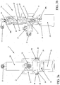
FIG. 1 shows a perspective view of a preferred embodiment of the cartridge-type single-screw pump according to the present invention; -
FIG. 2 shows a perspective view of the cartridge-type single-screw pump ofFIG. 1 in which the removable pumping cartridge and the external fixed pump body are mutually separated; -
FIG. 3a shows a front view of the cartridge-type single-screw pump ofFIG. 1 ; -
FIG. 3b shows a sectional view of the cartridge-type single-screw pump according to section line A-A inFIG. 1 ; and -
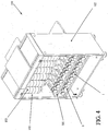
FIG. 4 shows a perspective view of a preferred embodiment of the dye-meter according to the present invention. - The cartridge-type single-screw pump according to the present invention is adapted to volumetrically batch a certain amount of a fluid, for example a colouring component, preferably contained inside storage means and to deliver it towards suitable distributing means, such as for example a nozzle or a delivering head like those known in the art.
- As will be seen below in the present description, the practical and technical arrangement of individual components of the cartridge-type single-
screw pump 1 according to the present invention is within the scope of any technician in the art, as well as the numerous, but trivial, possible design and constructive variations thereof. - With particular reference to
FIG. 1, 2 3a and 3b , it is possible to note that the cartridge-type single-screw pump 1 according to the present invention is composed of an externalfixed pump body 10 and aremovable pumping cartridge 20, this latter one being adapted to be inserted in at least oneinsertion seat 11 of the externalfixed pump body 10 and to operatively cooperate with this latter one. - In particular, the external
fixed pump body 10 comprises a first inletfluidic duct 12 and a second outletfluidic duct 13, such first and second ducts respectively 12 and 13 communicating with the interior of theinsertion seat 11. The first inletfluidic duct 12 is particularly adapted to be connected, by interposing circuit fluidic connection means (not shown and preferably made as at least one duct), to fluid storage means (such fluid being preferably a dye) to be batched and delivered. The first inletfluidic duct 12 can further be equipped with at least one adjustingvalve 15 for the fluid flow-rate that crosses it. The second outletfluidic duct 13 instead is particularly adapted to be connected to the fluid distributing means by interposing other circuit fluidic connection means (not shown). - Obviously, the external fixed
pump body 10 can be equipped with suitable securing means to a machinery, such as for example a dye-meter, to be served: for example, the securing means can be made as at least onebracket 14 to be fixed to the machinery through screws or bolts. - The
removable pumping cartridge 20 is in particular a pump with progressive recesses (device usually employed for pumping extremely viscous substances, such as for example concretes) comprising anexternal housing 21 containing apump stator 22 inside which aninternal rotor 23 can rotate under the action of at least one drivingmotor 24 connected therewith (in particular, the drive shaft 24a of thedriving motor 24 is preferably connected to theinternal rotor 23 in such a way as to be coaxial with the rotation axis of theinternal rotor 23 itself). In particular, theinternal rotor 23 is shaped as a worm screw with progressive recesses whose relative rotation with respect to thestator 22 causes a translation movement of the fluid present inside it. Theexternal housing 21 is equipped with a first inlet opening 25 adapted to correspond with the first inletfluidic duct 12 and to communicate the first inletfluidic duct 12 with the interior of thestator 22 when theremovable pumping cartridge 20 is inserted inside theinsertion seat 11 of the externalfixed pump body 10. - Next to the outlet end of the pump with progressive recesses, the
external housing 21 is equipped with a second outlet opening 26 adapted to correspond with the second outletfluidic duct 13 and to communicate thestator 22 interior with the second outletfluidic duct 13 itself when theremovable pumping cartridge 20 is inserted inside theinsertion seat 11 of the externalfixed pump body 10. Preferably, the second outlet opening 26 is realised as an attachment nipple equipped withrelated sealing means 26a adapted to be inserted and tightly coupled inside the second outletfluidic duct 13. - Along the external surface of the
external housing 21, it is possible to provide for the arrangement of other sealing means, such as for example at least one gasket 27 (as an example, theexternal housing 21 of thepump 1 according to the invention shown in the Figures is equipped with two sealing gaskets 27), adapted to perform a suitable seal betweenexternal housing 21 andinsertion seat 11 of the externalfixed pump body 10. - When actuated by the
driving motor 24, the pump with progressive recesses of theremovable pumping cartridge 20, during the rotation movement of itsinternal rotor 23, transfers certain amounts of fluid, entering inside thestator 22 through the first inletfluidic duct 12 and the first inlet opening 25, towards and through the second outlet opening 26 and the second outletfluidic duct 13. - The advantages deriving from the use of the pump with progressive recesses in the
removable pumping cartridge 20 are numerous: - when the
internal rotor 23 is unmoving with respect to thestator 22, the pump with progressive recesses guarantees a perfect seal; - the reliability of the pump with progressive recesses is practically total, since the single moving part is the
internal rotor 23 and the wear due to revolving friction due to the relative movement betweeninternal rotor 23 andstator 22 is neglectable; - contrary to traditional pumping systems, such as for example piston pumps, in which the pumping effect is cyclic due to the piston stroke, the pump with progressive recesses allows a continuous fluid delivery;
- the pump with progressive recesses allows an extremely accurate volumetric fluid delivery: in fact, the delivered volumetric batching is proportional to the rotation performed by the
internal rotor 23, whose rotation is controlled down to the order of fraction of a degree through thedriving motor 24; - once having ended the fluid delivery, imposing a counter-rotation of a suitable amount to the
internal rotor 23, it is possible to suck part of the fluid remained inside thestator 22, consequently avoiding possible drippings at distribution means level. - In order to make the
removable pumping cartridge 20 integral with the externalfixed pump body 10, and thereby make the operation of thepump 1 according to the present invention safer, more reliable and efficient, theexternal housing 21 can be equipped with securing means to theinsertion seat 11; preferably, as shown in the Figures, the securing means can be made as afirst flange 28 integral with theremovable pumping cartridge 20, adapted to be coupled with a respectivesecond flange 18 integral with the externalfixed pump body 10, such first and second flanges respectively 28 and 18 adapted to be mutually connected through adequate connection means, such as for example screws orbolts 29. - Therfore, contrary to what has been proposed by the prior art, in which in case of malfunction or maintenance of a batching and delivering device, this latter one must be almost completely disassembled and possibly cleaned from dye deposits remaining inside it, the cartridge-type single-
screw pump 1 according to the present invention allows obtaining the same results by simply and quickly withdrawing theremovable pumping cartridge 20 from the externalfixed pump body 10 and replacing it with another newremovable pumping cartridge 20. - The present invention further refers to a dye-meter equipped with at least one cartridge-type single-
screw pump 1 according to the present invention and as previously described. With reference in particular toFIG. 4 , it is possible to note that a dye-meter 100 according to the present invention comprises a supportingstructure 101, that obviously can be equipped withremovable coating panels 102 in order to protect thepump 1 from external agents containing at least one cartridge-type single-screw pump 1, whose first inletfluidic duct 12 is connected through circuit fluidic connection means (not shown) to storage means (preferably made as at least one tank 103) of a colouring component and whose second outletfluidic duct 13 is connected through other circuit fluidic connection means (not shown) to the distributing means (not shown) of the colouring component itself, under which a vessel (not shown) can be arranged, adapted to collect the final colouring compound. The dye-meter 100 according to the present invention can also comprise managing means that, in particular, by operating on the drivingmotor 24 of eachpump 1, check the correct batching and delivery of individual colouring components to obtain the final colouring compound depending on a certain composition formula. Advantageously, the managing means of the dye-meter 100 can be those substantially known for managing and driving traditional dye-meters; in particular, the managing means can comprise a known PC through which thepump 1 operation can be managed and, among other things, formulations of final colouring compounds can be inserted, amended and/or modified. - Obviously, the number and arrangement of the above components, and in particular of the cartridge-type single-
screw pumps 1 according to the present invention, can be different, and particularly depending on the variety of colouring compounds that the dye-meter 100 according to the present invention must be able to produce.
Claims (14)
- Cartridge-type single-screw pump (1) adapted to volumetrically batch and deliver a certain amount of a fluid contained inside storage means and to deliver such fluid towards distributing means, said single-screw pump (1) comprising an external fixed pump body (10) and a removable pumping cartridge (20), said removable pumping cartridge (20) being adapted to be inserted in at least one insertion seat (11) of said external fixed pump body (10) in order to operatively cooperate with this latter one, said removable pumping cartridge (20) comprising an external housing (21) containing a stator (22) inside which an internal rotor (23) is able to rotate under the action of at least one driving motor (24) connected therewith, a first inlet opening (25) adapted to correspond with a first inlet fluidic tube (12) and to communicate said first inlet fluidic tube (12) with an interior of said stator (22) when said removable pumping cartridge (20) is inserted inside said insertion seat (11) of said external fixed pump body (10), and said external housing (21) being equipped with a second outlet opening (26) adapted to correspond with a second outlet fluidic tube (13) and to communicate the inside of said stator (22) with said second outlet fluidic tube (13) when said removable pumping cartridge (20) is inserted inside said insertion seat (11) of said external fixed pump body (10), characterised in that said second outlet opening (26) is a connection nipple equipped with sealing means (26a) adapted to be inserted in said second outlet fluidic tube (13).
- Pump (1) according to claim 1, characterised in that said external fixed pump body (10) comprises a first inlet fluidic tube (12) and a second outlet fluidic tube (13), said first and second tubes (12, 13) communicating with an interior of said insertion seat (11).
- Pump (1) according to claim 2, characterised in that said first inlet fluidic tube (12) is connected, by interposing connecting means for fluids, to said storage means.
- Pump (1) according to claim 2 or 3, characterised in that said first inlet fluidic tube (12) is equipped with at least one adjusting valve (15).
- Pump (1) according to claim 2, characterised in that said second outlet fluidic tube (13) is connected, by interposing connecting means for fluids, to said distribution means.
- Pump (1) according to claim 1, characterised in that a drive shaft (24a) of said driving motor (24) is connected to said internal rotor (23) in order to be coaxial with a rotation axis of said internal rotor (23).
- Pump (1) according to claim 1, characterised in that said internal rotor (23) is shaped as a worm screw with progressive recesses.
- Pump (1) according to any one of the previous claims, characterised in that said external housing (21) is externally equipped with means for performing a sealing with the insertion seat (11) of said external fixed pump body (10).
- Pump (1) according to any one of the previous claims, characterised in that said external housing (21) is equipped with means for attaching said removable pumping cartridge (20) to said insertion seat (11).
- Pump (1) according to claim 9, characterised in that said attaching means are a first flange (28) integral with said removable pumping cartridge (20) adapted to be coupled with a respective second flange (18) integral with said external fixed pump body (10), said first and second flanges (28, 18) being adapted to be mutually connected through connection means, such as screws or bolts (29).
- Dye-meter (100) characterised in that it comprises at least one cartridge-type single-screw pump (1) according to any one of claims 1 to 10.
- Dye-meter (100) according to claim 11, characterised in that it comprises a supporting structure (101) containing at least one cartridge-type single-screw pump (1), whose first inlet fluidic tube (12) is connected through connecting means for fluids to storage means of a colouring component and whose second outlet fluidic tube (13) is connected through other connecting means for fluids to distributing means of said colouring component.
- Dye-meter (100) according to claim 11, characterised in that said storage means comprise at least one tank (71).
- Dye-meter (100) according to claim 11, characterised in that said supporting structure (101) is equipped with removable coating panels (102).
Applications Claiming Priority (1)
| Application Number | Priority Date | Filing Date | Title |
|---|---|---|---|
| PCT/IT2007/000149 WO2008105007A1 (en) | 2007-03-01 | 2007-03-01 | Cartridge -type single-screw pump and dye-meter equipped with such pump |
Publications (2)
| Publication Number | Publication Date |
|---|---|
| EP2118489A1 EP2118489A1 (en) | 2009-11-18 |
| EP2118489B1 true EP2118489B1 (en) | 2016-07-13 |
Family
ID=38626627
Family Applications (1)
| Application Number | Title | Priority Date | Filing Date |
|---|---|---|---|
| EP07736656.5A Active EP2118489B1 (en) | 2007-03-01 | 2007-03-01 | Cartridge -type single-screw pump and dye-meter equipped with such pump |
Country Status (5)
| Country | Link |
|---|---|
| US (1) | US8556134B2 (en) |
| EP (1) | EP2118489B1 (en) |
| CN (1) | CN101965457B (en) |
| ES (1) | ES2599209T3 (en) |
| WO (1) | WO2008105007A1 (en) |
Families Citing this family (6)
| Publication number | Priority date | Publication date | Assignee | Title |
|---|---|---|---|---|
| ITTO20130689A1 (en) * | 2013-08-12 | 2013-11-11 | Stan Engineering Corp S R L | DISPENSER DEVICE, IN PARTICULAR FOR PASTOSI OR CREMOSI PRODUCTS. |
| JP2017535412A (en) * | 2014-10-07 | 2017-11-30 | アクセス ビジネス グループ インターナショナル リミテッド ライアビリティ カンパニー | Personal preparation device |
| EP3483434B1 (en) | 2014-10-13 | 2023-03-22 | Alfa S.r.l. | Positive-displacement pump and pumping group for fluid products and method for the use thereof |
| IT201700045807A1 (en) * | 2017-04-28 | 2017-07-28 | Hero Europe S R L | Device, dosage system for powdered, liquid, pasty or creamy products and dispensing machine comprising this device |
| BR102019005114B1 (en) * | 2019-03-15 | 2023-12-05 | Leandro José Agostini | PROGRESSIVE CAVITY PUMP FOR TINTOMETRIC INDUSTRY |
| DE102023122236B4 (en) * | 2023-08-21 | 2025-05-28 | Viscotec Pumpen- U. Dosiertechnik Gmbh | Progressive cavity pump, dosing system and process |
Family Cites Families (13)
| Publication number | Priority date | Publication date | Assignee | Title |
|---|---|---|---|---|
| US3966098A (en) * | 1974-09-17 | 1976-06-29 | The Raymond Lee Organization, Inc. | Paint applicator |
| US5609275A (en) * | 1993-06-21 | 1997-03-11 | Gencorp Inc. | Metering apparatus having a screw member |
| US6138925A (en) * | 1998-11-16 | 2000-10-31 | Eugene O'neill | Texturizer dispensing apparatus |
| US6302662B1 (en) * | 1999-07-24 | 2001-10-16 | Ivek Corporation | Liquid dispensing systems and methods |
| DE50108332D1 (en) * | 2001-10-30 | 2006-01-12 | Grundfos As | Submersible pump |
| US6688499B2 (en) * | 2002-04-25 | 2004-02-10 | Jie Zhang | Liquid dispenser with screw pump |
| DE20302534U1 (en) * | 2003-02-17 | 2003-06-18 | TRW Fahrwerksysteme GmbH & Co. KG, 40547 Düsseldorf | Motor-pump assembly |
| JP2007524026A (en) * | 2003-06-18 | 2007-08-23 | トーマス インダストリーズ インコーポレーテツド | Hybrid perturbation pump |
| JP4280204B2 (en) | 2004-06-15 | 2009-06-17 | Okiセミコンダクタ株式会社 | Semiconductor device |
| US20060003980A1 (en) | 2004-07-02 | 2006-01-05 | Shamsuddin Shaikh | Cobalt(II) complexes as protein tyrosine kinase inhibitors |
| US20060011656A1 (en) * | 2004-07-16 | 2006-01-19 | Ming-Te Tu | Liquid extruding device |
| GB0504664D0 (en) | 2005-03-05 | 2005-04-13 | Inflow Control Solutions Ltd | Method, device and apparatus |
| US7690405B2 (en) * | 2005-07-18 | 2010-04-06 | Fluid Management, Inc. | Multiple fluid dispenser |
-
2007
- 2007-03-01 ES ES07736656.5T patent/ES2599209T3/en active Active
- 2007-03-01 CN CN200780052441.4A patent/CN101965457B/en active Active
- 2007-03-01 WO PCT/IT2007/000149 patent/WO2008105007A1/en not_active Ceased
- 2007-03-01 US US12/528,954 patent/US8556134B2/en active Active
- 2007-03-01 EP EP07736656.5A patent/EP2118489B1/en active Active
Also Published As
| Publication number | Publication date |
|---|---|
| US8556134B2 (en) | 2013-10-15 |
| US20100102092A1 (en) | 2010-04-29 |
| ES2599209T3 (en) | 2017-01-31 |
| WO2008105007A1 (en) | 2008-09-04 |
| CN101965457B (en) | 2014-03-19 |
| CN101965457A (en) | 2011-02-02 |
| EP2118489A1 (en) | 2009-11-18 |
Similar Documents
| Publication | Publication Date | Title |
|---|---|---|
| EP2118489B1 (en) | Cartridge -type single-screw pump and dye-meter equipped with such pump | |
| US8622248B2 (en) | Modular dye meter and method of preparing compounds | |
| CN100339625C (en) | Valve assembly | |
| EP2045060B1 (en) | Two component metering pump assembly | |
| EP2054622B1 (en) | Delivery pump | |
| US11530699B2 (en) | Horizontally split screw-spindle pump | |
| CN110701017B (en) | Precision servo plunger metering pump | |
| TW201518630A (en) | Multi-point seal lubrication system | |
| CN114215715A (en) | Metering pump | |
| US11953007B2 (en) | Rotary lobe pump with internal bearing | |
| US11428214B1 (en) | Compact pump with reduced vibration and reduced thermal degradation | |
| GB1579806A (en) | Metering pumps | |
| US6095776A (en) | Peristalic rubber impeller pump | |
| US11518553B2 (en) | Combination metering assembly for filling liquid products into containers | |
| EP2143485A2 (en) | Modular dye meter | |
| BR112015012372B1 (en) | PROGRESSIVE CAVITY AND CASING WHEEL PUMP | |
| CA2404715C (en) | Rotary valve and piston pump assembly and tank dispenser therefor | |
| HUT71691A (en) | Pump for feeding or transporting liquids and liqui form materials | |
| CN107076126A (en) | Positive displacement pump and pumping unit for fluid products and method of using same | |
| JP4873764B2 (en) | Fluid mixing equipment | |
| CN213885920U (en) | A paint mixing component | |
| EP3033524B1 (en) | Batching/delivering system comprising at least one remotely actuated volumetric batching pump | |
| CN210385600U (en) | Coating allotment agitating unit | |
| EP1795988A1 (en) | Arrangement for ratio-controlled dispensing of plural componet materials | |
| US11136970B2 (en) | Positive displacement pump with shaft-mounted sleeve |
Legal Events
| Date | Code | Title | Description |
|---|---|---|---|
| PUAI | Public reference made under article 153(3) epc to a published international application that has entered the european phase |
Free format text: ORIGINAL CODE: 0009012 |
|
| 17P | Request for examination filed |
Effective date: 20090904 |
|
| AK | Designated contracting states |
Kind code of ref document: A1 Designated state(s): AT BE BG CH CY CZ DE DK EE ES FI FR GB GR HU IE IS IT LI LT LU LV MC NL PL PT RO SE SI SK TR |
|
| DAX | Request for extension of the european patent (deleted) | ||
| GRAP | Despatch of communication of intention to grant a patent |
Free format text: ORIGINAL CODE: EPIDOSNIGR1 |
|
| INTG | Intention to grant announced |
Effective date: 20160216 |
|
| GRAS | Grant fee paid |
Free format text: ORIGINAL CODE: EPIDOSNIGR3 |
|
| GRAA | (expected) grant |
Free format text: ORIGINAL CODE: 0009210 |
|
| AK | Designated contracting states |
Kind code of ref document: B1 Designated state(s): AT BE BG CH CY CZ DE DK EE ES FI FR GB GR HU IE IS IT LI LT LU LV MC NL PL PT RO SE SI SK TR |
|
| REG | Reference to a national code |
Ref country code: GB Ref legal event code: FG4D |
|
| REG | Reference to a national code |
Ref country code: AT Ref legal event code: REF Ref document number: 812574 Country of ref document: AT Kind code of ref document: T Effective date: 20160715 Ref country code: CH Ref legal event code: EP |
|
| REG | Reference to a national code |
Ref country code: IE Ref legal event code: FG4D |
|
| REG | Reference to a national code |
Ref country code: DE Ref legal event code: R096 Ref document number: 602007046978 Country of ref document: DE |
|
| REG | Reference to a national code |
Ref country code: LT Ref legal event code: MG4D |
|
| REG | Reference to a national code |
Ref country code: NL Ref legal event code: MP Effective date: 20160713 |
|
| REG | Reference to a national code |
Ref country code: AT Ref legal event code: MK05 Ref document number: 812574 Country of ref document: AT Kind code of ref document: T Effective date: 20160713 |
|
| PG25 | Lapsed in a contracting state [announced via postgrant information from national office to epo] |
Ref country code: NL Free format text: LAPSE BECAUSE OF FAILURE TO SUBMIT A TRANSLATION OF THE DESCRIPTION OR TO PAY THE FEE WITHIN THE PRESCRIBED TIME-LIMIT Effective date: 20160713 Ref country code: IS Free format text: LAPSE BECAUSE OF FAILURE TO SUBMIT A TRANSLATION OF THE DESCRIPTION OR TO PAY THE FEE WITHIN THE PRESCRIBED TIME-LIMIT Effective date: 20161113 Ref country code: LT Free format text: LAPSE BECAUSE OF FAILURE TO SUBMIT A TRANSLATION OF THE DESCRIPTION OR TO PAY THE FEE WITHIN THE PRESCRIBED TIME-LIMIT Effective date: 20160713 Ref country code: FI Free format text: LAPSE BECAUSE OF FAILURE TO SUBMIT A TRANSLATION OF THE DESCRIPTION OR TO PAY THE FEE WITHIN THE PRESCRIBED TIME-LIMIT Effective date: 20160713 |
|
| REG | Reference to a national code |
Ref country code: ES Ref legal event code: FG2A Ref document number: 2599209 Country of ref document: ES Kind code of ref document: T3 Effective date: 20170131 |
|
| PG25 | Lapsed in a contracting state [announced via postgrant information from national office to epo] |
Ref country code: SE Free format text: LAPSE BECAUSE OF FAILURE TO SUBMIT A TRANSLATION OF THE DESCRIPTION OR TO PAY THE FEE WITHIN THE PRESCRIBED TIME-LIMIT Effective date: 20160713 Ref country code: PT Free format text: LAPSE BECAUSE OF FAILURE TO SUBMIT A TRANSLATION OF THE DESCRIPTION OR TO PAY THE FEE WITHIN THE PRESCRIBED TIME-LIMIT Effective date: 20161114 Ref country code: LV Free format text: LAPSE BECAUSE OF FAILURE TO SUBMIT A TRANSLATION OF THE DESCRIPTION OR TO PAY THE FEE WITHIN THE PRESCRIBED TIME-LIMIT Effective date: 20160713 Ref country code: PL Free format text: LAPSE BECAUSE OF FAILURE TO SUBMIT A TRANSLATION OF THE DESCRIPTION OR TO PAY THE FEE WITHIN THE PRESCRIBED TIME-LIMIT Effective date: 20160713 Ref country code: GR Free format text: LAPSE BECAUSE OF FAILURE TO SUBMIT A TRANSLATION OF THE DESCRIPTION OR TO PAY THE FEE WITHIN THE PRESCRIBED TIME-LIMIT Effective date: 20161014 Ref country code: AT Free format text: LAPSE BECAUSE OF FAILURE TO SUBMIT A TRANSLATION OF THE DESCRIPTION OR TO PAY THE FEE WITHIN THE PRESCRIBED TIME-LIMIT Effective date: 20160713 Ref country code: BE Free format text: LAPSE BECAUSE OF FAILURE TO SUBMIT A TRANSLATION OF THE DESCRIPTION OR TO PAY THE FEE WITHIN THE PRESCRIBED TIME-LIMIT Effective date: 20160713 |
|
| REG | Reference to a national code |
Ref country code: FR Ref legal event code: PLFP Year of fee payment: 11 |
|
| REG | Reference to a national code |
Ref country code: DE Ref legal event code: R097 Ref document number: 602007046978 Country of ref document: DE |
|
| PG25 | Lapsed in a contracting state [announced via postgrant information from national office to epo] |
Ref country code: EE Free format text: LAPSE BECAUSE OF FAILURE TO SUBMIT A TRANSLATION OF THE DESCRIPTION OR TO PAY THE FEE WITHIN THE PRESCRIBED TIME-LIMIT Effective date: 20160713 Ref country code: RO Free format text: LAPSE BECAUSE OF FAILURE TO SUBMIT A TRANSLATION OF THE DESCRIPTION OR TO PAY THE FEE WITHIN THE PRESCRIBED TIME-LIMIT Effective date: 20160713 |
|
| PLBE | No opposition filed within time limit |
Free format text: ORIGINAL CODE: 0009261 |
|
| STAA | Information on the status of an ep patent application or granted ep patent |
Free format text: STATUS: NO OPPOSITION FILED WITHIN TIME LIMIT |
|
| PG25 | Lapsed in a contracting state [announced via postgrant information from national office to epo] |
Ref country code: SK Free format text: LAPSE BECAUSE OF FAILURE TO SUBMIT A TRANSLATION OF THE DESCRIPTION OR TO PAY THE FEE WITHIN THE PRESCRIBED TIME-LIMIT Effective date: 20160713 Ref country code: BG Free format text: LAPSE BECAUSE OF FAILURE TO SUBMIT A TRANSLATION OF THE DESCRIPTION OR TO PAY THE FEE WITHIN THE PRESCRIBED TIME-LIMIT Effective date: 20161013 Ref country code: CZ Free format text: LAPSE BECAUSE OF FAILURE TO SUBMIT A TRANSLATION OF THE DESCRIPTION OR TO PAY THE FEE WITHIN THE PRESCRIBED TIME-LIMIT Effective date: 20160713 Ref country code: DK Free format text: LAPSE BECAUSE OF FAILURE TO SUBMIT A TRANSLATION OF THE DESCRIPTION OR TO PAY THE FEE WITHIN THE PRESCRIBED TIME-LIMIT Effective date: 20160713 |
|
| 26N | No opposition filed |
Effective date: 20170418 |
|
| PG25 | Lapsed in a contracting state [announced via postgrant information from national office to epo] |
Ref country code: SI Free format text: LAPSE BECAUSE OF FAILURE TO SUBMIT A TRANSLATION OF THE DESCRIPTION OR TO PAY THE FEE WITHIN THE PRESCRIBED TIME-LIMIT Effective date: 20160713 |
|
| REG | Reference to a national code |
Ref country code: CH Ref legal event code: PL |
|
| PG25 | Lapsed in a contracting state [announced via postgrant information from national office to epo] |
Ref country code: MC Free format text: LAPSE BECAUSE OF FAILURE TO SUBMIT A TRANSLATION OF THE DESCRIPTION OR TO PAY THE FEE WITHIN THE PRESCRIBED TIME-LIMIT Effective date: 20160713 |
|
| REG | Reference to a national code |
Ref country code: IE Ref legal event code: MM4A |
|
| PG25 | Lapsed in a contracting state [announced via postgrant information from national office to epo] |
Ref country code: LU Free format text: LAPSE BECAUSE OF NON-PAYMENT OF DUE FEES Effective date: 20170301 |
|
| PG25 | Lapsed in a contracting state [announced via postgrant information from national office to epo] |
Ref country code: CH Free format text: LAPSE BECAUSE OF NON-PAYMENT OF DUE FEES Effective date: 20170331 Ref country code: IE Free format text: LAPSE BECAUSE OF NON-PAYMENT OF DUE FEES Effective date: 20170301 Ref country code: LI Free format text: LAPSE BECAUSE OF NON-PAYMENT OF DUE FEES Effective date: 20170331 |
|
| REG | Reference to a national code |
Ref country code: FR Ref legal event code: PLFP Year of fee payment: 12 |
|
| PG25 | Lapsed in a contracting state [announced via postgrant information from national office to epo] |
Ref country code: HU Free format text: LAPSE BECAUSE OF FAILURE TO SUBMIT A TRANSLATION OF THE DESCRIPTION OR TO PAY THE FEE WITHIN THE PRESCRIBED TIME-LIMIT; INVALID AB INITIO Effective date: 20070301 |
|
| PG25 | Lapsed in a contracting state [announced via postgrant information from national office to epo] |
Ref country code: CY Free format text: LAPSE BECAUSE OF NON-PAYMENT OF DUE FEES Effective date: 20160713 |
|
| PGFP | Annual fee paid to national office [announced via postgrant information from national office to epo] |
Ref country code: ES Payment date: 20250401 Year of fee payment: 19 |
|
| P01 | Opt-out of the competence of the unified patent court (upc) registered |
Free format text: CASE NUMBER: APP_31281/2025 Effective date: 20250630 |
|
| PGFP | Annual fee paid to national office [announced via postgrant information from national office to epo] |
Ref country code: GB Payment date: 20260327 Year of fee payment: 20 |
|
| PGFP | Annual fee paid to national office [announced via postgrant information from national office to epo] |
Ref country code: DE Payment date: 20260305 Year of fee payment: 20 |
|
| PGFP | Annual fee paid to national office [announced via postgrant information from national office to epo] |
Ref country code: IT Payment date: 20260204 Year of fee payment: 20 |
|
| PGFP | Annual fee paid to national office [announced via postgrant information from national office to epo] |
Ref country code: FR Payment date: 20260123 Year of fee payment: 20 |
|
| PGFP | Annual fee paid to national office [announced via postgrant information from national office to epo] |
Ref country code: TR Payment date: 20260325 Year of fee payment: 20 |