EP2117758B1 - Schweissreparatur von innen liegenden defekten - Google Patents
Schweissreparatur von innen liegenden defekten Download PDFInfo
- Publication number
- EP2117758B1 EP2117758B1 EP07704543.3A EP07704543A EP2117758B1 EP 2117758 B1 EP2117758 B1 EP 2117758B1 EP 07704543 A EP07704543 A EP 07704543A EP 2117758 B1 EP2117758 B1 EP 2117758B1
- Authority
- EP
- European Patent Office
- Prior art keywords
- welding
- powder
- crack
- flux
- turbine
- Prior art date
- Legal status (The legal status is an assumption and is not a legal conclusion. Google has not performed a legal analysis and makes no representation as to the accuracy of the status listed.)
- Not-in-force
Links
Images


Classifications
-
- B—PERFORMING OPERATIONS; TRANSPORTING
- B23—MACHINE TOOLS; METAL-WORKING NOT OTHERWISE PROVIDED FOR
- B23K—SOLDERING OR UNSOLDERING; WELDING; CLADDING OR PLATING BY SOLDERING OR WELDING; CUTTING BY APPLYING HEAT LOCALLY, e.g. FLAME CUTTING; WORKING BY LASER BEAM
- B23K10/00—Welding or cutting by means of a plasma
-
- B—PERFORMING OPERATIONS; TRANSPORTING
- B23—MACHINE TOOLS; METAL-WORKING NOT OTHERWISE PROVIDED FOR
- B23K—SOLDERING OR UNSOLDERING; WELDING; CLADDING OR PLATING BY SOLDERING OR WELDING; CUTTING BY APPLYING HEAT LOCALLY, e.g. FLAME CUTTING; WORKING BY LASER BEAM
- B23K26/00—Working by laser beam, e.g. welding, cutting or boring
- B23K26/20—Bonding
- B23K26/32—Bonding taking account of the properties of the material involved
-
- B—PERFORMING OPERATIONS; TRANSPORTING
- B23—MACHINE TOOLS; METAL-WORKING NOT OTHERWISE PROVIDED FOR
- B23K—SOLDERING OR UNSOLDERING; WELDING; CLADDING OR PLATING BY SOLDERING OR WELDING; CUTTING BY APPLYING HEAT LOCALLY, e.g. FLAME CUTTING; WORKING BY LASER BEAM
- B23K26/00—Working by laser beam, e.g. welding, cutting or boring
- B23K26/34—Laser welding for purposes other than joining
- B23K26/342—Build-up welding
-
- B—PERFORMING OPERATIONS; TRANSPORTING
- B23—MACHINE TOOLS; METAL-WORKING NOT OTHERWISE PROVIDED FOR
- B23K—SOLDERING OR UNSOLDERING; WELDING; CLADDING OR PLATING BY SOLDERING OR WELDING; CUTTING BY APPLYING HEAT LOCALLY, e.g. FLAME CUTTING; WORKING BY LASER BEAM
- B23K35/00—Rods, electrodes, materials, or media, for use in soldering, welding, or cutting
- B23K35/02—Rods, electrodes, materials, or media, for use in soldering, welding, or cutting characterised by mechanical features, e.g. shape
- B23K35/0222—Rods, electrodes, materials, or media, for use in soldering, welding, or cutting characterised by mechanical features, e.g. shape for use in soldering or brazing
- B23K35/0244—Powders, particles or spheres; Preforms made therefrom
- B23K35/025—Pastes, creams or slurries
-
- B—PERFORMING OPERATIONS; TRANSPORTING
- B23—MACHINE TOOLS; METAL-WORKING NOT OTHERWISE PROVIDED FOR
- B23K—SOLDERING OR UNSOLDERING; WELDING; CLADDING OR PLATING BY SOLDERING OR WELDING; CUTTING BY APPLYING HEAT LOCALLY, e.g. FLAME CUTTING; WORKING BY LASER BEAM
- B23K35/00—Rods, electrodes, materials, or media, for use in soldering, welding, or cutting
- B23K35/22—Rods, electrodes, materials, or media, for use in soldering, welding, or cutting characterised by the composition or nature of the material
- B23K35/36—Selection of non-metallic compositions, e.g. coatings or fluxes; Selection of soldering or welding materials, conjoint with selection of non-metallic compositions, both selections being of interest
- B23K35/3601—Selection of non-metallic compositions, e.g. coatings or fluxes; Selection of soldering or welding materials, conjoint with selection of non-metallic compositions, both selections being of interest with inorganic compounds as principal constituents
- B23K35/3602—Carbonates, basic oxides or hydroxides
-
- B—PERFORMING OPERATIONS; TRANSPORTING
- B23—MACHINE TOOLS; METAL-WORKING NOT OTHERWISE PROVIDED FOR
- B23K—SOLDERING OR UNSOLDERING; WELDING; CLADDING OR PLATING BY SOLDERING OR WELDING; CUTTING BY APPLYING HEAT LOCALLY, e.g. FLAME CUTTING; WORKING BY LASER BEAM
- B23K35/00—Rods, electrodes, materials, or media, for use in soldering, welding, or cutting
- B23K35/22—Rods, electrodes, materials, or media, for use in soldering, welding, or cutting characterised by the composition or nature of the material
- B23K35/36—Selection of non-metallic compositions, e.g. coatings or fluxes; Selection of soldering or welding materials, conjoint with selection of non-metallic compositions, both selections being of interest
- B23K35/3601—Selection of non-metallic compositions, e.g. coatings or fluxes; Selection of soldering or welding materials, conjoint with selection of non-metallic compositions, both selections being of interest with inorganic compounds as principal constituents
- B23K35/3608—Titania or titanates
-
- B—PERFORMING OPERATIONS; TRANSPORTING
- B23—MACHINE TOOLS; METAL-WORKING NOT OTHERWISE PROVIDED FOR
- B23K—SOLDERING OR UNSOLDERING; WELDING; CLADDING OR PLATING BY SOLDERING OR WELDING; CUTTING BY APPLYING HEAT LOCALLY, e.g. FLAME CUTTING; WORKING BY LASER BEAM
- B23K9/00—Arc welding or cutting
- B23K9/04—Welding for other purposes than joining, e.g. built-up welding
-
- B—PERFORMING OPERATIONS; TRANSPORTING
- B23—MACHINE TOOLS; METAL-WORKING NOT OTHERWISE PROVIDED FOR
- B23P—METAL-WORKING NOT OTHERWISE PROVIDED FOR; COMBINED OPERATIONS; UNIVERSAL MACHINE TOOLS
- B23P6/00—Restoring or reconditioning objects
- B23P6/002—Repairing turbine components, e.g. moving or stationary blades, rotors
- B23P6/007—Repairing turbine components, e.g. moving or stationary blades, rotors using only additive methods, e.g. build-up welding
-
- B—PERFORMING OPERATIONS; TRANSPORTING
- B23—MACHINE TOOLS; METAL-WORKING NOT OTHERWISE PROVIDED FOR
- B23P—METAL-WORKING NOT OTHERWISE PROVIDED FOR; COMBINED OPERATIONS; UNIVERSAL MACHINE TOOLS
- B23P6/00—Restoring or reconditioning objects
- B23P6/04—Repairing fractures or cracked metal parts or products, e.g. castings
- B23P6/045—Repairing fractures or cracked metal parts or products, e.g. castings of turbine components, e.g. moving or stationary blades, rotors, etc.
-
- C—CHEMISTRY; METALLURGY
- C22—METALLURGY; FERROUS OR NON-FERROUS ALLOYS; TREATMENT OF ALLOYS OR NON-FERROUS METALS
- C22C—ALLOYS
- C22C19/00—Alloys based on nickel or cobalt
- C22C19/03—Alloys based on nickel or cobalt based on nickel
- C22C19/05—Alloys based on nickel or cobalt based on nickel with chromium
- C22C19/051—Alloys based on nickel or cobalt based on nickel with chromium and Mo or W
- C22C19/055—Alloys based on nickel or cobalt based on nickel with chromium and Mo or W with the maximum Cr content being at least 20% but less than 30%
-
- C—CHEMISTRY; METALLURGY
- C22—METALLURGY; FERROUS OR NON-FERROUS ALLOYS; TREATMENT OF ALLOYS OR NON-FERROUS METALS
- C22C—ALLOYS
- C22C19/00—Alloys based on nickel or cobalt
- C22C19/07—Alloys based on nickel or cobalt based on cobalt
-
- F—MECHANICAL ENGINEERING; LIGHTING; HEATING; WEAPONS; BLASTING
- F01—MACHINES OR ENGINES IN GENERAL; ENGINE PLANTS IN GENERAL; STEAM ENGINES
- F01D—NON-POSITIVE DISPLACEMENT MACHINES OR ENGINES, e.g. STEAM TURBINES
- F01D5/00—Blades; Blade-carrying members; Heating, heat-insulating, cooling or antivibration means on the blades or the members
- F01D5/005—Repairing methods or devices
-
- B—PERFORMING OPERATIONS; TRANSPORTING
- B23—MACHINE TOOLS; METAL-WORKING NOT OTHERWISE PROVIDED FOR
- B23K—SOLDERING OR UNSOLDERING; WELDING; CLADDING OR PLATING BY SOLDERING OR WELDING; CUTTING BY APPLYING HEAT LOCALLY, e.g. FLAME CUTTING; WORKING BY LASER BEAM
- B23K2101/00—Articles made by soldering, welding or cutting
- B23K2101/001—Turbines
-
- B—PERFORMING OPERATIONS; TRANSPORTING
- B23—MACHINE TOOLS; METAL-WORKING NOT OTHERWISE PROVIDED FOR
- B23K—SOLDERING OR UNSOLDERING; WELDING; CLADDING OR PLATING BY SOLDERING OR WELDING; CUTTING BY APPLYING HEAT LOCALLY, e.g. FLAME CUTTING; WORKING BY LASER BEAM
- B23K2101/00—Articles made by soldering, welding or cutting
- B23K2101/34—Coated articles ; Surface treated articles
-
- B—PERFORMING OPERATIONS; TRANSPORTING
- B23—MACHINE TOOLS; METAL-WORKING NOT OTHERWISE PROVIDED FOR
- B23K—SOLDERING OR UNSOLDERING; WELDING; CLADDING OR PLATING BY SOLDERING OR WELDING; CUTTING BY APPLYING HEAT LOCALLY, e.g. FLAME CUTTING; WORKING BY LASER BEAM
- B23K2103/00—Materials to be soldered, welded or cut
- B23K2103/02—Iron or ferrous alloys
- B23K2103/04—Steel or steel alloys
- B23K2103/05—Stainless steel
-
- B—PERFORMING OPERATIONS; TRANSPORTING
- B23—MACHINE TOOLS; METAL-WORKING NOT OTHERWISE PROVIDED FOR
- B23K—SOLDERING OR UNSOLDERING; WELDING; CLADDING OR PLATING BY SOLDERING OR WELDING; CUTTING BY APPLYING HEAT LOCALLY, e.g. FLAME CUTTING; WORKING BY LASER BEAM
- B23K2103/00—Materials to be soldered, welded or cut
- B23K2103/08—Non-ferrous metals or alloys
-
- B—PERFORMING OPERATIONS; TRANSPORTING
- B23—MACHINE TOOLS; METAL-WORKING NOT OTHERWISE PROVIDED FOR
- B23K—SOLDERING OR UNSOLDERING; WELDING; CLADDING OR PLATING BY SOLDERING OR WELDING; CUTTING BY APPLYING HEAT LOCALLY, e.g. FLAME CUTTING; WORKING BY LASER BEAM
- B23K2103/00—Materials to be soldered, welded or cut
- B23K2103/18—Dissimilar materials
- B23K2103/26—Alloys of Nickel and Cobalt and Chromium
-
- B—PERFORMING OPERATIONS; TRANSPORTING
- B23—MACHINE TOOLS; METAL-WORKING NOT OTHERWISE PROVIDED FOR
- B23K—SOLDERING OR UNSOLDERING; WELDING; CLADDING OR PLATING BY SOLDERING OR WELDING; CUTTING BY APPLYING HEAT LOCALLY, e.g. FLAME CUTTING; WORKING BY LASER BEAM
- B23K2103/00—Materials to be soldered, welded or cut
- B23K2103/50—Inorganic materials other than metals or composite materials
- B23K2103/52—Ceramics
-
- F—MECHANICAL ENGINEERING; LIGHTING; HEATING; WEAPONS; BLASTING
- F05—INDEXING SCHEMES RELATING TO ENGINES OR PUMPS IN VARIOUS SUBCLASSES OF CLASSES F01-F04
- F05D—INDEXING SCHEME FOR ASPECTS RELATING TO NON-POSITIVE-DISPLACEMENT MACHINES OR ENGINES, GAS-TURBINES OR JET-PROPULSION PLANTS
- F05D2230/00—Manufacture
- F05D2230/20—Manufacture essentially without removing material
- F05D2230/23—Manufacture essentially without removing material by permanently joining parts together
- F05D2230/232—Manufacture essentially without removing material by permanently joining parts together by welding
-
- F—MECHANICAL ENGINEERING; LIGHTING; HEATING; WEAPONS; BLASTING
- F05—INDEXING SCHEMES RELATING TO ENGINES OR PUMPS IN VARIOUS SUBCLASSES OF CLASSES F01-F04
- F05D—INDEXING SCHEME FOR ASPECTS RELATING TO NON-POSITIVE-DISPLACEMENT MACHINES OR ENGINES, GAS-TURBINES OR JET-PROPULSION PLANTS
- F05D2230/00—Manufacture
- F05D2230/80—Repairing, retrofitting or upgrading methods
-
- Y—GENERAL TAGGING OF NEW TECHNOLOGICAL DEVELOPMENTS; GENERAL TAGGING OF CROSS-SECTIONAL TECHNOLOGIES SPANNING OVER SEVERAL SECTIONS OF THE IPC; TECHNICAL SUBJECTS COVERED BY FORMER USPC CROSS-REFERENCE ART COLLECTIONS [XRACs] AND DIGESTS
- Y02—TECHNOLOGIES OR APPLICATIONS FOR MITIGATION OR ADAPTATION AGAINST CLIMATE CHANGE
- Y02T—CLIMATE CHANGE MITIGATION TECHNOLOGIES RELATED TO TRANSPORTATION
- Y02T50/00—Aeronautics or air transport
- Y02T50/60—Efficient propulsion technologies, e.g. for aircraft
Definitions
- the invention relates to a method for welding repair of internal cracks in components.
- Components are tested in a variety of ways after manufacture or after use, which may then identify internal defects that often require repair.
- JP 0 428 4975 discloses a method for welding repair of a crack in a component.
- the object is achieved by a method for welding repair of internal defects according to claim 1.
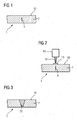
- FIG. 1 shows a component 1, 120, 130, 155, which has a crack 4 in the substrate 7, which does not extend to the outer surface 10, that is completely enclosed in the substrate 7 of the component 1, 120, 130, 155.
- the material of the substrate 7, in particular in turbine components, is preferably a nickel- or cobalt-based alloy.
- nickel- or cobalt-based alloys used can be found in US Pat FIG. 7 ,
- the method can also be applied to steels (on stainless steels, eg SS410) as well as to parts of a compressor or to guide grooves.
- FIG. 2 schematically an arrangement is shown to the crack 4 according to FIG. 1 to repair.
- Internal cracks 4 are detected, preferably by means of an eddy current method 5.
- a so-called “active” flux 13 known in the art is applied to the surface 10 in the region above the crack 4.
- the flux 13 is preferably in powder form.
- the flux 13 is made of powder.
- the flux 13 can preferably also be sprayed on as a suspension or as an alcohol or water-based slip, with or without a binder applied. Likewise, preferably, the powder may be pressed, so be present as a strip or sheet.
- fine-grained powder (+ 1 ⁇ m / -45 ⁇ m) is used.
- TIG welding is used.
- a welding device 16 TIG welding device, laser welding device, etc.
- the skilled person can set laser parameters (duration, intensity, power,%) Material-specifically and component-specifically in order to completely detect a crack 4 in a melting zone 22.
- the melting zone does not extend through the entire thickness of the component 7.
- the melting zone 22 may preferably extend over the entire thickness.
- the edited area is still revised.
- the flux 13 is preferably a powder. Also preferably, the flux 13 may be a powder mixture.
- a composition of SiO 2 or Fe 2 O 3 may be preferably used.
- titanium oxide (0-60wt%), nickel oxide (0-40wt%) and manganese silicide (0-10wt%).
- the improved energy transfer during TIG welding / remelting with surface-active substances is achieved by an enrichment of the arc with electrons.
- the arc is narrowed and thus generates a significantly higher energy density and improved melt bath depth.
- FIG. 4 shows by way of example a gas turbine 100 in a longitudinal partial section.
- the gas turbine 100 has inside a rotatably mounted about a rotation axis 102 rotor 103 with a shaft 101, which is also referred to as a turbine runner.
- an intake housing 104 a compressor 105, for example, a toroidal combustion chamber 110, in particular annular combustion chamber, with a plurality of coaxially arranged burners 107, a turbine 108 and the exhaust housing 109th
- a compressor 105 for example, a toroidal combustion chamber 110, in particular annular combustion chamber, with a plurality of coaxially arranged burners 107, a turbine 108 and the exhaust housing 109th
- the annular combustion chamber 110 communicates with an annular annular hot gas channel 111, for example. There, for example, form four successive turbine stages 112, the turbine 108th
- Each turbine stage 112 is formed, for example, from two blade rings. As seen in the direction of flow of a working medium 113, in the hot gas channel 111 of a row of guide vanes 115, a series 125 formed of rotor blades 120 follows.
- the guide vanes 130 are fastened to an inner housing 138 of a stator 143, whereas the moving blades 120 of a row 125 are attached to the rotor 103 by means of a turbine disk 133, for example.
- air 105 is sucked in and compressed by the compressor 105 through the intake housing 104.
- the compressed air provided at the turbine-side end of the compressor 105 is supplied to the burners 107 where it is mixed with a fuel.
- the mixture is then burned to form the working fluid 113 in the combustion chamber 110.
- the working medium 113 flows along the hot gas channel 111 past the guide vanes 130 and the rotor blades 120.
- the working medium 113 expands in a pulse-transmitting manner so that the rotor blades 120 drive the rotor 103 and drive the machine coupled to it.
- the components exposed to the hot working medium 113 are subject to thermal loads during operation of the gas turbine 100.
- the guide vanes 130 and rotor blades 120 of the first turbine stage 112, viewed in the flow direction of the working medium 113, are subjected to the greatest thermal stress in addition to the heat shield elements lining the annular combustion chamber 110.
- substrates of the components may have a directional structure, i. they are monocrystalline (SX structure) or have only longitudinal grains (DS structure).
- iron-, nickel- or cobalt-based superalloys are used as the material for the components, in particular for the turbine blade 120, 130 and components of the combustion chamber 110.
- Such superalloys are for example from EP 1 204 776 B1 .
- EP 1 306 454 .
- the vane 130 has a guide vane foot (not shown here) facing the inner housing 138 of the turbine 108 and a vane head opposite the vane foot.
- the vane head faces the rotor 103 and fixed to a mounting ring 140 of the stator 143.
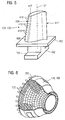
- FIG. 5 shows a perspective view of a blade 120 or guide vane 130 of a turbomachine, which extends along a longitudinal axis 121.
- the turbomachine may be a gas turbine of an aircraft or a power plant for power generation, a steam turbine or a compressor.
- the blade 120, 130 has along the longitudinal axis 121 consecutively a fastening region 400, a blade platform 403 adjacent thereto and an airfoil 406 and a blade tip 415.
- the blade 130 may have at its blade tip 415 another platform (not shown).
- a blade root 183 is formed, which serves for attachment of the blades 120, 130 to a shaft or a disc (not shown).
- the blade root 183 is designed, for example, as a hammer head. Other designs as Christmas tree or Schwalbenschwanzfuß are possible.
- the blade 120, 130 has a leading edge 409 and a trailing edge 412 for a medium flowing past the airfoil 406.
- Such superalloys are for example from EP 1 204 776 B1 .
- EP 1 306 454 .
- the blade 120, 130 can be made by a casting process, also by directional solidification, by a forging process, by a milling process or combinations thereof.
- Workpieces with a monocrystalline structure or structures are used as components for machines which are exposed to high mechanical, thermal and / or chemical stresses during operation.
- Such monocrystalline workpieces takes place e.g. by directed solidification from the melt.
- These are casting processes in which the liquid metallic alloy is transformed into a monocrystalline structure, i. to the single-crystal workpiece, or directionally solidified.
- dendritic crystals are aligned along the heat flow and form either a columnar grain structure (columnar, ie grains that run the entire length of the workpiece and here, in common parlance, referred to as directionally solidified) or a monocrystalline structure, ie the whole Value piece exists from a single crystal.
- directionally solidified columnar grain structure
- monocrystalline structure ie the whole Value piece exists from a single crystal.
- directionally solidified microstructures which means both single crystals that have no grain boundaries or at most small angle grain boundaries, and stem crystal structures that have probably longitudinal grain boundaries but no transverse grain boundaries. These second-mentioned crystalline structures are also known as directionally solidified structures.
- the blades 120, 130 may have coatings against corrosion or oxidation, e.g. M is at least one element of the group iron (Fe), cobalt (Co), nickel (Ni), X is an active element and stands for yttrium (Y) and / or silicon and / or at least one element of the rare ones Earth, or hafnium (Hf)).
- M is at least one element of the group iron (Fe), cobalt (Co), nickel (Ni)
- X is an active element and stands for yttrium (Y) and / or silicon and / or at least one element of the rare ones Earth, or hafnium (Hf)).
- Such alloys are known from the EP 0 486 489 B1 . EP 0 786 017 B1 . EP 0 412 397 B1 or EP 1 306 454 A1 which are to be part of this disclosure with regard to the chemical composition of the alloy.
- the density is preferably 95% of the theoretical density.
- the layer composition comprises Co-30Ni-28Cr-8A1-0.6Y-0.7Si or Co-28Ni-24Cr-10Al-0.6Y.
- nickel-based protective layers such as Ni-10Cr-12Al-0,6Y-3Re are also preferably used or Ni-12Co-21Cr-11Al-0.4Y-2Re or Ni-25Co-17Cr-10Al-0.4Y-1.5Re.
- thermal barrier coating which is preferably the outermost layer, and consists for example of ZrO 2 , Y 2 O 3 -ZrO 2 , ie it is not, partially or completely stabilized by yttria and / or calcium oxide and / or magnesium oxide.
- the thermal barrier coating covers the entire MCrAlX layer.
- suitable coating methods e.g. Electron beam evaporation (EB-PVD) produces stalk-shaped grains in the thermal barrier coating.
- the thermal barrier coating may have porous, micro- or macro-cracked grains for better thermal shock resistance.
- the thermal barrier coating is therefore preferably more porous than the MCrAlX layer.
- the blade 120, 130 may be hollow or solid. If the blade 120, 130 is to be cooled, it is hollow and may still film cooling holes 418 (indicated by dashed lines) on.
- the FIG. 6 shows a combustion chamber 110 of the gas turbine 100.
- the combustion chamber 110 is configured, for example, as a so-called annular combustion chamber, in which a plurality of circumferentially arranged around a rotation axis 102 around burners 107 open into a common combustion chamber space 154, the flames 156 produce.
- the combustion chamber 110 is configured in its entirety as an annular structure, which is positioned around the axis of rotation 102 around.
- the combustion chamber 110 is designed for a comparatively high temperature of the working medium M of about 1000 ° C to 1600 ° C. Even with these, for the materials unfavorable operating parameters, the combustion chamber wall 153 is provided on its side facing the working medium M with an inner lining formed from heat shield elements 155.
- the heat shield elements 155 are then, for example, hollow and possibly still have cooling holes (not shown) which open into the combustion chamber space 154.
- Each heat shield element 155 made of an alloy is equipped on the working medium side with a particularly heat-resistant protective layer (MCrAlX layer and / or ceramic coating) or is made of high-temperature-resistant material (solid ceramic blocks).
- M is at least one element of the group iron (Fe), cobalt (Co), nickel (Ni), X is an active element and stands for yttrium (Y) and / or silicon and / or at least one element of the rare earths, or hafnium (Hf).
- MCrAlX means: M is at least one element of the group iron (Fe), cobalt (Co), nickel (Ni), X is an active element and stands for yttrium (Y) and / or silicon and / or at least one element of the rare earths, or hafnium (Hf).
- Such alloys are known from the EP 0 486 489 B1 .
- EP 0 412 397 B1 or EP 1 306 454 A1 which are to be part of this disclosure with regard to the chemical composition of the alloy.
- a ceramic thermal barrier coating may be present and consists for example of ZrO 2 , Y 2 O 3 -ZrO 2 , ie it is not, partially or completely stabilized by yttria and / or calcium oxide and / or magnesium oxide.
- Electron beam evaporation produces stalk-shaped grains in the thermal barrier coating.
- thermal barrier coating may have porous, micro- or macro-cracked grains for better thermal shock resistance.
- Refurbishment means that turbine blades 120, 130, heat shield elements 155 may need to be deprotected (e.g., by sandblasting) after use. This is followed by removal of the corrosion and / or oxidation layers or products. Optionally, cracks in the turbine blade 120, 130 or the heat shield element 155 are also repaired. This is followed by a re-coating of the turbine blades 120, 130, heat shield elements 155 and a renewed use of the turbine blades 120, 130 or the heat shield elements 155.
Landscapes
- Engineering & Computer Science (AREA)
- Mechanical Engineering (AREA)
- Physics & Mathematics (AREA)
- Chemical & Material Sciences (AREA)
- Optics & Photonics (AREA)
- Plasma & Fusion (AREA)
- Inorganic Chemistry (AREA)
- Organic Chemistry (AREA)
- Metallurgy (AREA)
- Materials Engineering (AREA)
- General Engineering & Computer Science (AREA)
- Turbine Rotor Nozzle Sealing (AREA)
- Other Surface Treatments For Metallic Materials (AREA)
- Coating By Spraying Or Casting (AREA)
Description
- Die Erfindung betrifft ein Verfahren zur Schweißreparatur von innen liegenden Rissen in Bauteilen.
- Bauteile werden nach der Herstellung oder nach dem Einsatz auf verschiedene Art und Weise geprüft, wobei dann gegebenenfalls innen liegende Defekte festgestellt werden, die oft repariert werden müssen.
- Nach dem Stand der Technik wird Material um den Riss herausgearbeitet, sowohl wenn der Riss an der Oberfläche in Erscheinung tritt als auch wenn er innen liegend ist, d.h. keine Verbindung zur äußeren Oberfläche hat. Solche herausgearbeiteten Risse werden dann zugelötet oder zugeschweißt. Dieses Ausarbeiten ist zeitaufwändig, da es einen weiteren Bearbeitungsschritt darstellt. Insbesondere muss darauf geachtet werden, dass der ganze Riss herausgearbeitet wird.
-
JP 0 428 4975 - Es ist daher Aufgabe der Erfindung ein Verfahren gemäß Anspruch 1 aufzuzeigen, das die Schweißreparatur von innen liegenden Defekten vereinfacht.
- Die Aufgabe wird gelöst durch ein Verfahren zur Schweißreparatur von innen liegenden Defekten gemäß Anspruch 1.
- Dabei wird ein Flussmittel verwendet, das auf der Oberfläche des Bauteils in der Nähe des Risses aufgebraucht wird und dann geschweißt wird.
- In den Unteransprüchen sind weitere vorteilhafte Maßnahmen aufgelistet, die beliebig miteinander kombiniert werden können, um weitere Vorteile zu erzielen.
- Es zeigen:
- Figur 1, 2, 3
- den Ablauf des Verfahrens,
- Figur 4
- eine Gasturbine,
- Figur 5
- perspektivisch eine Turbinenschaufel,
- Figur 6
- perspektivisch eine Brennkammer und
- Figur 7
- eine Liste von Superlegierungen.
-
Figur 1 zeigt ein Bauteil 1, 120, 130, 155, das im Substrat 7 einen Riss 4 aufweist, der nicht bis zur äußeren Oberfläche 10 sich erstreckt, also vollkommen im Substrat 7 des Bauteils 1, 120, 130, 155 eingeschlossen ist. - Das Material des Substrats 7, insbesondere bei Turbinenbauteilen, ist vorzugsweise eine nickel- oder kobaltbasierte Legierung. Beispiele für verwendete nickel- oder kobaltbasierte Legierungen finden sich in der
Figur 7 . - Ebenso lässt sich das Verfahren anwenden auf Stähle (auf rostfreie Edelstähle, z. B. SS410) sowie an Teilen eines Verdichters oder an Führungsnuten.
- In
Figur 2 ist schematisch eine Anordnung gezeigt, um den Riss 4 gemäßFigur 1 zu, reparieren. - Innen liegende Risse 4 werden detektiert, vorzugsweise mittels eines Wirbelstromverfahrens 5.
- Dann wird ein so genanntes "Aktiv"-Flussmittel 13, die aus dem Stand der Technik bekannt sind, auf die Oberfläche 10 im Bereich oberhalb des Risses 4 aufgebracht. Das Flussmittel 13 liegt vorzugsweise in Pulverform vor. Vorzugsweise besteht das Flussmittel 13 aus Pulver.
- Das Flussmittel 13 kann vorzugsweise auch als Suspension, oder als Schlicker auf Alkohol- oder Wasserbasis, mit oder ohne Binder, aufgetragen aufgepinselt, aufgesprüht werden. Ebenso vorzugsweise kann das Pulver gepresst, also als Streifen oder als Blech vorliegen.
- Für den Zusatzwerkstoff wird vorzugsweise feinkörniges Pulver (+1µm/-45µm) verwendet.
- Zum Schweißen werden vorzugsweise Schmelzschweißverfahren und/oder Plasmaschweißverfahren verwendet:
- Lichtbogenhandschweißen
- Metall-Lichtbogenschweißen mit Fülldrahtelektrode ohne Schutzgas;
- Unterpulverschweißen mit Drahtelektrode,
- Unterpulverschweißen mit Fülldrahtelektrode,
- Metall-Inertgasschweißen (MIG-Schweißen),
- Metall-Aktivgasschweißen (MAG-Schweißen),
- Metall-Aktivgasschweißen (MAG-Schweißen),
- Wolfram-Inertgasschweißen (WIG-Schweißen),
- Gasschweißen mit Sauerstoff-Acetylen-Flamme.
- Bevorzugt wird das WIG-Schweißen benutzt.
- Ebenso können andere Verfahren wie Laserschweißen, Elektronenstrahlschweißen verwendet werden.
- Mittels eines Schweißgeräts 16 (WIG-Schweißgerät, Laserschweißgerät, etc.), das ein Plasma 19 erzeugt oder Laserstrahlen 19 aussendet, wird das Flussmittel 13 aufgeschmolzen und der Bereich um den Riss 4 wird vollständig erfasst, so dass sich eine Aufschmelzzone 22 um den Riss 4 gemäß
Figur 3 bildet, die bis zu 8mm (= Schmelzbadtiefe) tief sein kann. Der Fachmann kann Laserparameter (Dauer, Intensität, Leistung,..) Materialspezifisch und Bauteilspezifisch einstellen, um einen Riss 4 vollständig in einer Aufschmelzzone 22 zu erfassen. - In
Figur 3 erstreckt sich die Aufschmelzzone nicht durch die gesamte Dicke des Bauteils 7. Ebenso kann sich insbesondere bei hohlen oder dünnwandigen Bauteilen die Aufschmelzzone 22 vorzugsweise über die gesamte Dicke erstrecken. - Eine weitere Schweißung ist nicht notwendig.
- Vorzugsweise wird die bearbeitete Stelle noch überarbeitet.
- Für das Flussmittel 13 kann ein Flussmittel aus dem Stand der Technik ausgewählt werden.
- Das Flussmittel 13 stellt vorzugsweise ein Pulver dar. Ebenso vorzugsweise kann das Flussmittel 13 eine Pulvermischung darstellen.
- Eine Zusammensetzung aus SiO2 oder Fe2O3 kann vorzugsweise verwendet werden.
- Ebenso vorzugsweise ist eine Zusammensetzung aus Titanoxid (0 - 60wt%), Nickeloxid (0 - 40wt%) sowie Mangansilizid (0-10wt%) zu verwenden.
- Die Kombinationen:
- Titanoxid
- Nickeloxid
- Mangansilizid
- Titanoxid/Nickeloxid
- Titanoxid/Mangansilizid
- Nickeloxid/Mangansilizid
- Titanoxid/Nickeloxid/Mangansilizid
- sind jeweils bevorzugte Ausführungsbeispiele.
- Die deutlich verbesserte Schmelzbadtiefe beim Laserschweißen und Umschmelzen von Rissen mit solchen "Aktiv"-Flussmitteln 13 bzw. so genannten oberflächenaktiven Suspensionen wird durch folgende Faktoren beeinflusst:
- a: Marangoni-Effekt: die Energie- und Wärmeübertragung beim Schweißen/Umschmelzen erfolgt durch Bewegung von flüssigem Metall im Schmelzbad. Werden die Bewegungen auf der Schmelzbadoberfläche nach Auswärts hingerichtet, wird das Schmelzbad breit und seicht. In einer Bewegung, die Inwärts gerichtet ist, wird das Schmelzbad schmal und tief. Die Art der Bewegung im Schmelzbad wird durch die Oberflächenspannung des flüssigen Metalls beeinflusst. Durch die gezielte Zugabe von oberflächenaktiven Substanzen (Zusatzwerkstoff) ist es möglich, die Oberflächenspannung im Schmelzbad so zu ändern, dass die Bewegung des flüssigen Metalls Inwärts gerichtet ist und damit eine deutlich verbesserte Schmelzbadtiefe erreicht wird.
- b: Verbesserte Absorption des Schweißstrahls: die oberflächenaktive Substanz wird im Laufe des Schweißprozesses umgeschmolzen und bildet eine sehr dünne Schicht (Schlacke) auf der Schmelzbadoberfläche. Diese dünne Schicht beeinflusst nicht nur die Oberflächenspannung des Schmelzbades, sondern gleichzeitig weist sie deutlich verbesserte Absorptionseigenschaften des Schweißstrahls auf als das flüssige Metall des Grundwerkstoffs. Damit ist es möglich, eine verbesserte Energieübertragung und Schmelzbadtiefe zu erzeugen, die unter bestimmten Umständen bis zu 4-8mm erreichen kann.
- Die verbesserte Energieübertragung beim WIG-Schweißen/Umschmelzen mit oberflächenaktiven Substanzen wird durch eine Anreicherung des Lichtbogens mit Elektronen erreicht. Durch diese Anreicherung wird der Lichtbogen verengt und damit eine deutlich höhere Energiedichte und verbesserte Schmelzbadtiefe erzeugt.
- Die
Figur 4 zeigt beispielhaft eine Gasturbine 100 in einem Längsteilschnitt. - Die Gasturbine 100 weist im Inneren einen um eine Rotationsachse 102 drehgelagerten Rotor 103 mit einer Welle 101 auf, der auch als Turbinenläufer bezeichnet wird.
- Entlang des Rotors 103 folgen aufeinander ein Ansauggehäuse 104, ein Verdichter 105, eine beispielsweise torusartige Brennkammer 110, insbesondere Ringbrennkammer, mit mehreren koaxial angeordneten Brennern 107, eine Turbine 108 und das Abgasgehäuse 109.
- Die Ringbrennkammer 110 kommuniziert mit einem beispielsweise ringförmigen Heißgaskanal 111. Dort bilden beispielsweise vier hintereinander geschaltete Turbinenstufen 112 die Turbine 108.
- Jede Turbinenstufe 112 ist beispielsweise aus zwei Schaufelringen gebildet. In Strömungsrichtung eines Arbeitsmediums 113 gesehen folgt im Heißgaskanal 111 einer Leitschaufelreihe 115 eine aus Laufschaufeln 120 gebildete Reihe 125.
- Die Leitschaufeln 130 sind dabei an einem Innengehäuse 138 eines Stators 143 befestigt, wohingegen die Laufschaufeln 120 einer Reihe 125 beispielsweise mittels einer Turbinenscheibe 133 am Rotor 103 angebracht sind.
- An dem Rotor 103 angekoppelt ist ein Generator oder eine Arbeitsmaschine (nicht dargestellt).
- Während des Betriebes der Gasturbine 100 wird vom Verdichter 105 durch das Ansauggehäuse 104 Luft 135 angesaugt und verdichtet. Die am turbinenseitigen Ende des Verdichters 105 bereitgestellte verdichtete Luft wird zu den Brennern 107 geführt und dort mit einem Brennmittel vermischt. Das Gemisch wird dann unter Bildung des Arbeitsmediums 113 in der Brennkammer 110 verbrannt. Von dort aus strömt das Arbeitsmedium 113 entlang des Heißgaskanals 111 vorbei an den Leitschaufeln 130 und den Laufschaufeln 120. An den Laufschaufeln 120 entspannt sich das Arbeitsmedium 113 impulsübertragend, so dass die Laufschaufeln 120 den Rotor 103 antreiben und dieser die an ihn angekoppelte Arbeitsmaschine.
- Die dem heißen Arbeitsmedium 113 ausgesetzten Bauteile unterliegen während des Betriebes der Gasturbine 100 thermischen Belastungen. Die Leitschaufeln 130 und Laufschaufeln 120 der in Strömungsrichtung des Arbeitsmediums 113 gesehen ersten Turbinenstufe 112 werden neben den die Ringbrennkammer 110 auskleidenden Hitzeschildelementen am meisten thermisch belastet.
- Um den dort herrschenden Temperaturen standzuhalten, können diese mittels eines Kühlmittels gekühlt werden.
- Ebenso können Substrate der Bauteile eine gerichtete Struktur aufweisen, d.h. sie sind einkristallin (SX-Struktur) oder weisen nur längsgerichtete Körner auf (DS-Struktur).
- Als Material für die Bauteile, insbesondere für die Turbinenschaufel 120, 130 und Bauteile der Brennkammer 110 werden beispielsweise eisen-, nickel- oder kobaltbasierte Superlegierungen verwendet.
- Solche Superlegierungen sind beispielsweise aus der
EP 1 204 776 B1 ,EP 1 306 454 ,EP 1 319 729 A1 ,WO 99/67435 WO 00/44949 - Die Leitschaufel 130 weist einen dem Innengehäuse 138 der Turbine 108 zugewandten Leitschaufelfuß (hier nicht dargestellt) und einen dem Leitschaufelfuß gegenüberliegenden Leitschaufelkopf auf. Der Leitschaufelkopf ist dem Rotor 103 zugewandt und an einem Befestigungsring 140 des Stators 143 festgelegt.
- Die
Figur 5 zeigt in perspektivischer Ansicht eine Laufschaufel 120 oder Leitschaufel 130 einer Strömungsmaschine, die sich entlang einer Längsachse 121 erstreckt. - Die Strömungsmaschine kann eine Gasturbine eines Flugzeugs oder eines Kraftwerks zur Elektrizitätserzeugung, eine Dampfturbine oder ein Kompressor sein.
- Die Schaufel 120, 130 weist entlang der Längsachse 121 aufeinander folgend einen Befestigungsbereich 400, eine daran angrenzende Schaufelplattform 403 sowie ein Schaufelblatt 406 und eine Schaufelspitze 415 auf.
- Als Leitschaufel 130 kann die Schaufel 130 an ihrer Schaufelspitze 415 eine weitere Plattform aufweisen (nicht dargestellt).
- Im Befestigungsbereich 400 ist ein Schaufelfuß 183 gebildet, der zur Befestigung der Laufschaufeln 120, 130 an einer Welle oder einer Scheibe dient (nicht dargestellt).
- Der Schaufelfuß 183 ist beispielsweise als Hammerkopf ausgestaltet. Andere Ausgestaltungen als Tannenbaum- oder Schwalbenschwanzfuß sind möglich.
- Die Schaufel 120, 130 weist für ein Medium, das an dem Schaufelblatt 406 vorbeiströmt, eine Anströmkante 409 und eine Abströmkante 412 auf.
- Bei herkömmlichen Schaufeln 120, 130 werden in allen Bereichen 400, 403, 406 der Schaufel 120, 130 beispielsweise massive metallische Werkstoffe, insbesondere Superlegierungen verwendet.
- Solche Superlegierungen sind beispielsweise aus der
EP 1 204 776 B1 ,EP 1 306 454 ,EP 1 319 729 A1 ,WO 99/67435 WO 00/44949 - Die Schaufel 120, 130 kann hierbei durch ein Gussverfahren, auch mittels gerichteter Erstarrung, durch ein Schmiedeverfahren, durch ein Fräsverfahren oder Kombinationen daraus gefertigt sein.
- Werkstücke mit einkristalliner Struktur oder Strukturen werden als Bauteile für Maschinen eingesetzt, die im Betrieb hohen mechanischen, thermischen und/oder chemischen Belastungen ausgesetzt sind.
- Die Fertigung von derartigen einkristallinen Werkstücken erfolgt z.B. durch gerichtetes Erstarren aus der Schmelze. Es handelt sich dabei um Gießverfahren, bei denen die flüssige metallische Legierung zur einkristallinen Struktur, d.h. zum einkristallinen Werkstück, oder gerichtet erstarrt.
- Dabei werden dendritische Kristalle entlang dem Wärmefluss ausgerichtet und bilden entweder eine stängelkristalline Kornstruktur (kolumnar, d.h. Körner, die über die ganze Länge des Werkstückes verlaufen und hier, dem allgemeinen Sprachgebrauch nach, als gerichtet erstarrt bezeichnet werden) oder eine einkristalline Struktur, d.h. das ganze Wertstück besteht aus einem einzigen Kristall. In diesen Verfahren muss man den Übergang zur globulitischen (polykristallinen) Erstarrung meiden, da sich durch ungerichtetes Wachstum notwendigerweise transversale und longitudinale Korngrenzen ausbilden, welche die guten Eigenschaften des gerichtet erstarrten oder einkristallinen Bauteiles zunichte machen.
- Ist allgemein von gerichtet erstarrten Gefügen die Rede, so sind damit sowohl Einkristalle gemeint, die keine Korngrenzen oder höchstens Kleinwinkelkorngrenzen aufweisen, als auch Stängelkristallstrukturen, die wohl in longitudinaler Richtung verlaufende Korngrenzen, aber keine transversalen Korngrenzen aufweisen. Bei diesen zweitgenannten kristallinen Strukturen spricht man auch von gerichtet erstarrten Gefügen (directionally solidified structures).
- Solche Verfahren sind aus der
US-PS 6,024,792 und derEP 0 892 090 A1 bekannt; diese Schriften sind bzgl. des Erstarrungsverfahrens Teil der Offenbarung. - Ebenso können die Schaufeln 120, 130 Beschichtungen gegen Korrosion oder Oxidation aufweisen, z. B. (MCrAlX; M ist zumindest ein Element der Gruppe Eisen (Fe), Kobalt (Co), Nickel (Ni), X ist ein Aktivelement und steht für Yttrium (Y) und/oder Silizium und/oder zumindest ein Element der Seltenen Erden, bzw. Hafnium (Hf)). Solche Legierungen sind bekannt aus der
EP 0 486 489 B1 ,EP 0 786 017 B1 ,EP 0 412 397 B1 oderEP 1 306 454 A1 , die bzgl. der chemischen Zusammensetzung der Legierung Teil dieser Offenbarung sein sollen. - Die Dichte liegt vorzugsweise bei 95% der theoretischen Dichte.
- Auf der MCrAlX-Schicht (als Zwischenschicht oder als äußerste Schicht) bildet sich eine schützende Aluminiumoxidschicht (TGO = thermal grown oxide layer).
- Vorzugsweise weist die Schichtzusammensetzung Co-30Ni-28Cr-8A1-0,6Y-0,7Si oder Co-28Ni-24Cr-10Al-0,6Y auf. Neben diesen kobaltbasierten Schutzbeschichtungen werden auch vorzugsweise nickelbasierte Schutzschichten verwendet wie Ni-10Cr-12Al-0,6Y-3Re oder Ni-12Co-21Cr-11Al-0,4Y-2Re oder Ni-25Co-17Cr-10Al-0,4Y-1,5Re.
- Auf der MCrAlX kann noch eine Wärmedämmschicht vorhanden sein, die vorzugsweise die äußerste Schicht ist, und besteht beispielsweise aus ZrO2, Y2O3-ZrO2, d.h. sie ist nicht, teilweise oder vollständig stabilisiert durch Yttriumoxid und/oder Kalziumoxid und/oder Magnesiumoxid.
- Die Wärmedämmschicht bedeckt die gesamte MCrAlX-Schicht. Durch geeignete Beschichtungsverfahren wie z.B. Elektronenstrahlverdampfen (EB-PVD) werden stängelförmige Körner in der Wärmedämmschicht erzeugt.
- Andere Beschichtungsverfahren sind denkbar, z.B. atmosphärisches Plasmaspritzen (APS), LPPS, VPS oder CVD. Die Wärmedämmschicht kann poröse, mikro- oder makrorissbehaftete Körner zur besseren Thermoschockbeständigkeit aufweisen. Die Wärmedämmschicht ist also vorzugsweise poröser als die MCrAlX-Schicht.
- Die Schaufel 120, 130 kann hohl oder massiv ausgeführt sein. Wenn die Schaufel 120, 130 gekühlt werden soll, ist sie hohl und weist ggf. noch Filmkühllöcher 418 (gestrichelt angedeutet) auf.
- Die
Figur 6 zeigt eine Brennkammer 110 der Gasturbine 100. Die Brennkammer 110 ist beispielsweise als so genannte Ringbrennkammer ausgestaltet, bei der eine Vielzahl von in Umfangsrichtung um eine Rotationsachse 102 herum angeordneten Brennern 107 in einen gemeinsamen Brennkammerraum 154 münden, die Flammen 156 erzeugen. Dazu ist die Brennkammer 110 in ihrer Gesamtheit als ringförmige Struktur ausgestaltet, die um die Rotationsachse 102 herum positioniert ist. - Zur Erzielung eines vergleichsweise hohen Wirkungsgrades ist die Brennkammer 110 für eine vergleichsweise hohe Temperatur des Arbeitsmediums M von etwa 1000°C bis 1600°C ausgelegt. Um auch bei diesen, für die Materialien ungünstigen Betriebsparametern eine vergleichsweise lange Betriebsdauer zu ermöglichen, ist die Brennkammerwand 153 auf ihrer dem Arbeitsmedium M zugewandten Seite mit einer aus Hitzeschildelementen 155 gebildeten Innenauskleidung versehen.
- Aufgrund der hohen Temperaturen im Inneren der Brennkammer 110 kann zudem für die Hitzeschildelemente 155 bzw. für deren Halteelemente ein Kühlsystem vorgesehen sein. Die Hitzeschildelemente 155 sind dann beispielsweise hohl und weisen ggf. noch in den Brennkammerraum 154 mündende Kühllöcher (nicht dargestellt) auf.
- Jedes Hitzeschildelement 155 aus einer Legierung ist arbeitsmediumsseitig mit einer besonders hitzebeständigen Schutzschicht (MCrAlX-Schicht und/oder keramische Beschichtung) ausgestattet oder ist aus hochtemperaturbeständigem Material (massive keramische Steine) gefertigt.
- Diese Schutzschichten können ähnlich der Turbinenschaufeln sein, also bedeutet beispielsweise MCrAlX: M ist zumindest ein Element der Gruppe Eisen (Fe), Kobalt (Co), Nickel (Ni), X ist ein Aktivelement und steht für Yttrium (Y) und/oder Silizium und/oder zumindest ein Element der Seltenen Erden, bzw. Hafnium (Hf). Solche Legierungen sind bekannt aus der
EP 0 486 489 B1 ,EP 0 786 017 B1 ,EP 0 412 397 B1 oderEP 1 306 454 A1 , die bzgl. der chemischen Zusammensetzung der Legierung Teil dieser Offenbarung sein sollen. - Auf der MCrAlX kann noch eine beispielsweise keramische Wärmedämmschicht vorhanden sein und besteht beispielsweise aus ZrO2, Y2O3-ZrO2, d.h. sie ist nicht, teilweise oder vollständig stabilisiert durch Yttriumoxid und/oder Kalziumoxid und/oder Magnesiumoxid.
- Durch geeignete Beschichtungsverfahren wie z.B. Elektronenstrahlverdampfen (EB-PVD) werden stängelförmige Körner in der Wärmedämmschicht erzeugt.
- Andere Beschichtungsverfahren sind denkbar, z.B. atmosphärisches Plasmaspritzen (APS), LPPS, VPS oder CVD. Die Wärmedämmschicht kann poröse, mikro- oder makrorissbehaftete Körner zur besseren Thermoschockbeständigkeit aufweisen.
- Wiederaufarbeitung (Refurbishment) bedeutet, dass Turbinenschaufeln 120, 130, Hitzeschildelemente 155 nach ihrem Einsatz gegebenenfalls von Schutzschichten befreit werden müssen (z.B. durch Sandstrahlen). Danach erfolgt eine Entfernung der Korrosions- und/oder Oxidationsschichten bzw. -produkte. Gegebenenfalls werden auch noch Risse in der Turbinenschaufel 120, 130 oder dem Hitzeschildelement 155 repariert. Danach erfolgt eine Wiederbeschichtung der Turbinenschaufeln 120, 130, Hitzeschildelemente 155 und ein erneuter Einsatz der Turbinenschaufeln 120, 130 oder der Hitzeschildelemente 155.
Claims (14)
- Verfahren zur Schweißreparatur eines unter einer Oberfläche (10) eines Bauteils (1, 120, 130, 155) innen liegenden Risses (4),
bei dem ein Flussmittel (13) als Pulvermischung auf die Oberfläche (10) oberhalb des Risses (4) des Bauteils (1, 120, 130, 155) aufgebracht wird und
dann das Flussmittel (13) im Bereich um den innen liegenden Riss (4) mittels eines Schweißgeräts (16) aufgeschmolzen wird. - Verfahren nach Anspruch 1,
bei dem der Riss (4) vollständig durch eine Aufschmelzzone (22) beim Schweißen erfasst wird. - Verfahren nach Anspruch 1 oder 2,
bei dem ein Schmelzschweißverfahren verwendet wird. - Verfahren nach Anspruch 2 oder 3,
bei dem ein Plasmaschweißverfahren verwendet wird. - Verfahren nach Anspruch 2 oder 3,
bei dem ein Laserstrahlschweißen verwendet wird. - Verfahren nach Anspruch 2 oder 3,
bei dem ein Elektronenschweißverfahren verwendet wird. - Verfahren nach Anspruch 1,
bei dem das Pulver in Schlickerform vorliegt. - Verfahren nach Anspruch 1,
bei dem das Pulver in einer Suspension vorliegt. - Verfahren nach Anspruch 1, 7 oder 8,
bei dem das Pulver ein Binder enthält. - Verfahren nach Anspruch 1, 7 oder 8,
bei dem das Pulver keinen Binder enthält. - Verfahren nach Anspruch 1, 7, 8, 9 oder 10,
bei dem das Flussmittel (13) in gepresster Form, vorzugsweise als Blech verwendet wird. - Verfahren nach Anspruch 1, 7, 8, 9, 10 oder 11, bei dem das Pulver Titanoxid (TiO2) aufweist, insbesondere aus Titanoxid besteht.
- Verfahren nach Anspruch 1, 7, 8, 9, 10, 11 oder 12, bei dem das Pulver Nickeloxid aufweist,
insbesondere aus Nickeloxid besteht. - Verfahren nach Anspruch 1, 7, 8, 9, 10, 11, 12 oder 13, bei dem das Pulver Mangansilizid aufweist, insbesondere aus Mangansilizid besteht.
Applications Claiming Priority (1)
| Application Number | Priority Date | Filing Date | Title |
|---|---|---|---|
| PCT/EP2007/051368 WO2008098614A1 (de) | 2007-02-13 | 2007-02-13 | Schweissreparatur von innen liegenden defekten |
Publications (2)
| Publication Number | Publication Date |
|---|---|
| EP2117758A1 EP2117758A1 (de) | 2009-11-18 |
| EP2117758B1 true EP2117758B1 (de) | 2015-10-28 |
Family
ID=38544157
Family Applications (1)
| Application Number | Title | Priority Date | Filing Date |
|---|---|---|---|
| EP07704543.3A Not-in-force EP2117758B1 (de) | 2007-02-13 | 2007-02-13 | Schweissreparatur von innen liegenden defekten |
Country Status (3)
| Country | Link |
|---|---|
| US (1) | US8324526B2 (de) |
| EP (1) | EP2117758B1 (de) |
| WO (1) | WO2008098614A1 (de) |
Families Citing this family (32)
| Publication number | Priority date | Publication date | Assignee | Title |
|---|---|---|---|---|
| DE102006044555A1 (de) * | 2006-09-21 | 2008-04-03 | Mtu Aero Engines Gmbh | Reparaturverfahren |
| DE102008018708A1 (de) | 2008-04-14 | 2009-10-22 | Fraunhofer-Gesellschaft zur Förderung der angewandten Forschung e.V. | Verfahren zum Schweißen in Abhängigkeit einer Vorzugsrichtung des Substrats |
| EP2226149A1 (de) * | 2009-03-04 | 2010-09-08 | Siemens Aktiengesellschaft | Zweischritt-Schweissverfahren |
| DE102010031795B4 (de) * | 2010-07-20 | 2015-05-28 | Lufthansa Technik Ag | Verfahren zur Reparatur von Gasturbinenbauteilen aus keramischen Verbundwerkstoffen und Vorrichtung zur Durchführung des Verfahrens |
| US20120156020A1 (en) * | 2010-12-20 | 2012-06-21 | General Electric Company | Method of repairing a transition piece of a gas turbine engine |
| US20120181255A1 (en) * | 2011-01-13 | 2012-07-19 | Bruck Gerald J | Flux enhanced high energy density welding |
| US9352419B2 (en) * | 2011-01-13 | 2016-05-31 | Siemens Energy, Inc. | Laser re-melt repair of superalloys using flux |
| US20150275687A1 (en) * | 2011-01-13 | 2015-10-01 | Siemens Energy, Inc. | Localized repair of superalloy component |
| US9352413B2 (en) | 2011-01-13 | 2016-05-31 | Siemens Energy, Inc. | Deposition of superalloys using powdered flux and metal |
| US9283593B2 (en) | 2011-01-13 | 2016-03-15 | Siemens Energy, Inc. | Selective laser melting / sintering using powdered flux |
| US20130316183A1 (en) * | 2011-01-13 | 2013-11-28 | Anand A. Kulkarni, JR. | Localized repair of superalloy component |
| EP2591872A1 (de) * | 2011-11-11 | 2013-05-15 | Siemens Aktiengesellschaft | Umschmelzverfahren und anschließendes Auffüllen und Bauteil |
| EP2591877A1 (de) * | 2011-11-11 | 2013-05-15 | Siemens Aktiengesellschaft | Umschmelzverfahren unter reaktivem Gasgemisch |
| US10190220B2 (en) | 2013-01-31 | 2019-01-29 | Siemens Energy, Inc. | Functional based repair of superalloy components |
| WO2014120475A2 (en) * | 2013-01-31 | 2014-08-07 | Siemens Energy, Inc. | Deposition of superalloys using powdered flux and metal |
| EP2950950A1 (de) * | 2013-01-31 | 2015-12-09 | Siemens Energy, Inc. | Selektives laserschmelz-/sinterverfahren mit einem schweisspulver |
| CN104955612A (zh) * | 2013-01-31 | 2015-09-30 | 西门子能量股份有限公司 | 使用焊剂的超级合金的激光重熔修复方法 |
| US9770781B2 (en) * | 2013-01-31 | 2017-09-26 | Siemens Energy, Inc. | Material processing through optically transmissive slag |
| US20150027993A1 (en) * | 2013-07-29 | 2015-01-29 | Siemens Energy, Inc. | Flux for laser welding |
| WO2015017093A1 (en) * | 2013-08-01 | 2015-02-05 | Siemens Energy, Inc. | Repair of superalloy components by addition of powdered alloy and flux material |
| CN103481008B (zh) * | 2013-09-05 | 2017-01-25 | 通裕重工股份有限公司 | 一种深孔焊补工艺 |
| US9358629B1 (en) * | 2013-09-24 | 2016-06-07 | Siemens Energy, Inc. | Tungsten submerged arc welding using powdered flux |
| US20150360322A1 (en) * | 2014-06-12 | 2015-12-17 | Siemens Energy, Inc. | Laser deposition of iron-based austenitic alloy with flux |
| CN106573340A (zh) * | 2014-07-28 | 2017-04-19 | 西门子能源有限公司 | 利用熔剂对反射性金属的激光金属加工 |
| US9777574B2 (en) | 2014-08-18 | 2017-10-03 | Siemens Energy, Inc. | Method for repairing a gas turbine engine blade tip |
| US20160096234A1 (en) * | 2014-10-07 | 2016-04-07 | Siemens Energy, Inc. | Laser deposition and repair of reactive metals |
| US9782859B2 (en) * | 2015-07-16 | 2017-10-10 | Siemens Energy, Inc. | Slag free flux for additive manufacturing |
| CN105290589B (zh) * | 2015-11-10 | 2017-12-01 | 沈阳黎明航空发动机(集团)有限责任公司 | 一种钛合金进气机匣支板裂纹微束等离子焊修复方法 |
| EP3645209B1 (de) | 2017-06-27 | 2024-12-04 | Siemens Energy, Inc. | Verfahren und vorrichtung zum schweissen unter verwendung von elektroden mit koaxialer energiezufuhr |
| US20220088685A1 (en) * | 2020-09-18 | 2022-03-24 | Divergent Technologies, Inc. | Real time quality assurance for additive manufacturing |
| CN114589429B (zh) * | 2022-03-31 | 2022-08-30 | 广东省科学院中乌焊接研究所 | 一种用于叶轮增材修复的超级双相不锈钢药芯焊丝及其制备方法和应用 |
| US20260097449A1 (en) * | 2024-10-04 | 2026-04-09 | Pratt & Whitney Canada Corp. (P&Wc) | Surface alloy re-melting to increase resistance to oxidation |
Family Cites Families (40)
| Publication number | Priority date | Publication date | Assignee | Title |
|---|---|---|---|---|
| US3581039A (en) * | 1967-10-16 | 1971-05-25 | Kawasaki Steel Co | Method of one-side arc welding and backing material therefor |
| US3594542A (en) * | 1969-07-11 | 1971-07-20 | Sumikin Welding Electrode Co | Continuous lay down arc welding method |
| CH600980A5 (en) * | 1975-05-28 | 1978-06-30 | Rotterdamsche Droogdok Mij | Electroslag rectification of defects |
| US4022442A (en) * | 1975-06-13 | 1977-05-10 | Seiichi Okui | Welding and cutting apparatus |
| US4153832A (en) * | 1975-09-11 | 1979-05-08 | Kobe Steel, Ltd. | Overhead submerged arc welding process |
| DE2603020C3 (de) * | 1976-01-28 | 1978-10-12 | Eichhorn, Friedrich, Prof. Dr.-Ing., 5100 Aachen | Verfahren und Vorrichtung zum Elektro-Schlacke-Schweißen von Stahlblechen |
| US4229643A (en) * | 1978-06-12 | 1980-10-21 | Allis-Chalmers Corporation | Consumable welding electrode |
| US4604781A (en) * | 1985-02-19 | 1986-08-12 | Combustion Engineering, Inc. | Highly abrasive resistant material and grinding roll surfaced therewith |
| US4754118A (en) * | 1985-05-16 | 1988-06-28 | Mitsubishi Jukogyo Kabushiki Kaisha | Method for fabricating a structural assembly having narrow gaps |
| US4803340A (en) * | 1986-04-23 | 1989-02-07 | Kawasaki Steel Corp. | Covered arc-welding electrode |
| US4948936A (en) * | 1988-09-28 | 1990-08-14 | Gulf Engineering Company, Inc. | Flux cored arc welding process |
| EP0486489B1 (de) | 1989-08-10 | 1994-11-02 | Siemens Aktiengesellschaft | Hochtemperaturfeste korrosionsschutzbeschichtung, insbesondere für gasturbinenbauteile |
| DE3926479A1 (de) | 1989-08-10 | 1991-02-14 | Siemens Ag | Rheniumhaltige schutzbeschichtung, mit grosser korrosions- und/oder oxidationsbestaendigkeit |
| JPH04284975A (ja) * | 1991-03-12 | 1992-10-09 | Nippon Steel Weld Prod & Eng Co Ltd | サブマージアーク溶接金属の水素及び窒素低減方法 |
| US5474736A (en) * | 1992-09-25 | 1995-12-12 | Nippon Steel Welding Products & Engineering Co., Ltd. | Methods for manufacturing tubes filled with powdery and granular substances |
| RU2147624C1 (ru) | 1994-10-14 | 2000-04-20 | Сименс АГ | Защитный слой для защиты детали от коррозии, окисления и термической перегрузки, а также способ его изготовления |
| EP0892090B1 (de) | 1997-02-24 | 2008-04-23 | Sulzer Innotec Ag | Verfahren zum Herstellen von einkristallinen Strukturen |
| EP0861927A1 (de) * | 1997-02-24 | 1998-09-02 | Sulzer Innotec Ag | Verfahren zum Herstellen von einkristallinen Strukturen |
| US6153847A (en) * | 1997-06-06 | 2000-11-28 | Mitsui Engineering & Shipbuilding Company | Welding member and welding method |
| TW464582B (en) * | 1998-02-17 | 2001-11-21 | Lincoln Global Inc | Welding wire and method of making same |
| US6297472B1 (en) * | 1998-04-10 | 2001-10-02 | Aromatic Integrated Systems, Inc. | Welding system and method |
| WO1999067435A1 (en) | 1998-06-23 | 1999-12-29 | Siemens Aktiengesellschaft | Directionally solidified casting with improved transverse stress rupture strength |
| JP2000135570A (ja) * | 1998-10-30 | 2000-05-16 | Reeben:Kk | 溶接方法 |
| US6231692B1 (en) | 1999-01-28 | 2001-05-15 | Howmet Research Corporation | Nickel base superalloy with improved machinability and method of making thereof |
| EP1204776B1 (de) | 1999-07-29 | 2004-06-02 | Siemens Aktiengesellschaft | Hochtemperaturbeständiges bauteil und verfahren zur herstellung des hochtemperaturbeständigen bauteils |
| KR100343750B1 (ko) * | 2000-03-03 | 2002-07-20 | 고려용접봉 주식회사 | 내피트 및 내블로우 홀 성능이 우수한 아연도금 강판용접용 플럭스 코어드 와이어 |
| JP2001305271A (ja) * | 2000-04-24 | 2001-10-31 | Toshiba Corp | 原子力発電プラント用炉内機器の補修方法 |
| DE50104022D1 (de) | 2001-10-24 | 2004-11-11 | Siemens Ag | Rhenium enthaltende Schutzschicht zum Schutz eines Bauteils gegen Korrosion und Oxidation bei hohen Temperaturen |
| FR2832337B1 (fr) * | 2001-11-22 | 2004-01-23 | Commissariat Energie Atomique | Dispositif et procede de soudage hybride |
| EP1319729B1 (de) | 2001-12-13 | 2007-04-11 | Siemens Aktiengesellschaft | Hochtemperaturbeständiges Bauteil aus einkristalliner oder polykristalliner Nickel-Basis-Superlegierung |
| JP4304913B2 (ja) | 2002-04-17 | 2009-07-29 | 株式会社日立製作所 | 亀裂状欠陥の補修方法 |
| JP4284052B2 (ja) * | 2002-10-31 | 2009-06-24 | 株式会社東芝 | 欠陥補修方法 |
| EP1486282A1 (de) * | 2003-06-04 | 2004-12-15 | Delphi Technologies, Inc. | Verfahren und Vorrichtung zur Herstellung von metallischen Bauteilen und entsprechendes Bauteil |
| US6969826B2 (en) | 2004-04-08 | 2005-11-29 | General Electric Company | Welding process |
| WO2006132373A1 (ja) * | 2005-06-10 | 2006-12-14 | National Institute For Materials Science | 溶接ワイヤと溶接方法 |
| US8426762B2 (en) * | 2006-12-08 | 2013-04-23 | E.O. Paton Electric Welding Institute Of The National Academy Of Sciences Of Ukraine | Method of resistance butt welding using corrugated flux-filled metal inserts |
| US20080178734A1 (en) * | 2007-01-26 | 2008-07-31 | Lincoln Global, Inc. | Inert gas method of environmental control for moisture sensitive solids during storage and processing |
| US20090294426A1 (en) * | 2008-06-03 | 2009-12-03 | Bong William L | System and method for beam-to-column welding |
| EP2401110B1 (de) * | 2009-02-24 | 2020-11-04 | Esab AB | Lichtbogenschweissverfahren und vorrichtung zum lichtbogenschweissen |
| US8066174B2 (en) * | 2010-04-30 | 2011-11-29 | Siemens Energy, Inc. | Filler rotated friction stir welding |
-
2007
- 2007-02-13 US US12/526,797 patent/US8324526B2/en not_active Expired - Fee Related
- 2007-02-13 WO PCT/EP2007/051368 patent/WO2008098614A1/de not_active Ceased
- 2007-02-13 EP EP07704543.3A patent/EP2117758B1/de not_active Not-in-force
Also Published As
| Publication number | Publication date |
|---|---|
| EP2117758A1 (de) | 2009-11-18 |
| WO2008098614A1 (de) | 2008-08-21 |
| US20100116793A1 (en) | 2010-05-13 |
| US8324526B2 (en) | 2012-12-04 |
Similar Documents
| Publication | Publication Date | Title |
|---|---|---|
| EP2117758B1 (de) | Schweissreparatur von innen liegenden defekten | |
| EP2414127B1 (de) | Verfahren zum schweissen einer vertiefung eines bauteiles durch ausserhalb oder um die kontur angelegte schweissbahnen ; entsprechender bauteil | |
| EP2078579A1 (de) | Verfahren zum Löten eines Bauteils und Bauteil mit Löt- und Schweissstellen | |
| WO2009124802A1 (de) | Schweissverfahren mit geregeltem temperaturverlauf und eine vorrichtung dafür | |
| EP2450471A1 (de) | Verfahren zum Materialauftrag zur Reparatur eines Bauteils und Bauteil | |
| EP2100687A1 (de) | Potentialfreie Drahterwärmung beim Schweissen und Vorrichtung dafür | |
| EP2186594A1 (de) | Verfahren und Vorrichtung zur Vorwärmung beim Schweißen unter Verwendung eines zweiten Laserstrahles | |
| EP2312267A1 (de) | Verfahren zur Schichtdickenmessung mittels Lasertriangulation und Vorrichtung | |
| EP2369131A1 (de) | Reparatur von Bauteilkanten mittels PSP-Streifen und Bauteil | |
| EP2254726A2 (de) | Bauteil mit sich überlappenden schweissnähten und ein verfahren zur herstellung | |
| EP2062672A1 (de) | Verfahren zum Löten weiter Spalte | |
| WO2009127504A1 (de) | Bauteil mit schweissnaht und verfahren zur herstellung einer schweissnaht | |
| EP2226149A1 (de) | Zweischritt-Schweissverfahren | |
| WO2009100794A1 (de) | Verfahren zum aufschmelzen von gekrümmten oberflächen und eine vorrichtung | |
| EP2353725A1 (de) | Spritzdüse und Verfahren zum atmosphärischen Spritzen, Vorrichtung zum Beschichten und beschichtetes Bauteil | |
| EP2241397A1 (de) | Belotung von Löchern, Verfahren zum Beschichten und Lötgutstäbchen | |
| EP2583784A1 (de) | Vorbereitung einer Schweißstelle vor dem Schweißen und Bauteil | |
| WO2009106375A1 (de) | Vorrichtung zur strahlsteuerung und ein verfahren zur strahlsteuerung | |
| EP2558245B1 (de) | Germaniumhaltiges lot, ein bauteil mit einem lot und ein verfahren zum löten | |
| EP2487006A1 (de) | Mehrmalige Laserbearbeitung unter verschiedenen Winkeln | |
| EP2254725A1 (de) | Vorrichtung zum schweissen mit einer prozesskammer und ein schweissverfahren | |
| EP2196555A1 (de) | Pulvermischung aus Keramik und Glas, Bauteil mit Maskierung und Verfahren zur Anwendung | |
| EP1946881A1 (de) | Zusatzwerkstoff zum Schweissen von Superlegierungen und Reparaturschweissverfahren mit Zusatzwerkstoff | |
| EP2583781B1 (de) | Kombinierter Schweiß-Löt-Prozess zum Verbinden von zwei Komponenten | |
| EP2177643A1 (de) | Verfahren zum Reparieren einer Superlegierung mit dem gleichen Superlegierungspulver und Keramik |
Legal Events
| Date | Code | Title | Description |
|---|---|---|---|
| PUAI | Public reference made under article 153(3) epc to a published international application that has entered the european phase |
Free format text: ORIGINAL CODE: 0009012 |
|
| 17P | Request for examination filed |
Effective date: 20090629 |
|
| AK | Designated contracting states |
Kind code of ref document: A1 Designated state(s): AT BE BG CH CY CZ DE DK EE ES FI FR GB GR HU IE IS IT LI LT LU LV MC NL PL PT RO SE SI SK TR |
|
| DAX | Request for extension of the european patent (deleted) | ||
| RAP1 | Party data changed (applicant data changed or rights of an application transferred) |
Owner name: SIEMENS AKTIENGESELLSCHAFT |
|
| 17Q | First examination report despatched |
Effective date: 20150304 |
|
| GRAP | Despatch of communication of intention to grant a patent |
Free format text: ORIGINAL CODE: EPIDOSNIGR1 |
|
| INTG | Intention to grant announced |
Effective date: 20150520 |
|
| GRAS | Grant fee paid |
Free format text: ORIGINAL CODE: EPIDOSNIGR3 |
|
| GRAA | (expected) grant |
Free format text: ORIGINAL CODE: 0009210 |
|
| AK | Designated contracting states |
Kind code of ref document: B1 Designated state(s): AT BE BG CH CY CZ DE DK EE ES FI FR GB GR HU IE IS IT LI LT LU LV MC NL PL PT RO SE SI SK TR |
|
| REG | Reference to a national code |
Ref country code: GB Ref legal event code: FG4D Free format text: NOT ENGLISH |
|
| REG | Reference to a national code |
Ref country code: CH Ref legal event code: EP |
|
| REG | Reference to a national code |
Ref country code: AT Ref legal event code: REF Ref document number: 757648 Country of ref document: AT Kind code of ref document: T Effective date: 20151115 |
|
| REG | Reference to a national code |
Ref country code: IE Ref legal event code: FG4D Free format text: LANGUAGE OF EP DOCUMENT: GERMAN |
|
| REG | Reference to a national code |
Ref country code: DE Ref legal event code: R096 Ref document number: 502007014347 Country of ref document: DE |
|
| REG | Reference to a national code |
Ref country code: CH Ref legal event code: NV Representative=s name: SIEMENS SCHWEIZ AG, CH |
|
| REG | Reference to a national code |
Ref country code: FR Ref legal event code: PLFP Year of fee payment: 10 |
|
| REG | Reference to a national code |
Ref country code: LT Ref legal event code: MG4D |
|
| REG | Reference to a national code |
Ref country code: NL Ref legal event code: MP Effective date: 20151028 |
|
| PG25 | Lapsed in a contracting state [announced via postgrant information from national office to epo] |
Ref country code: NL Free format text: LAPSE BECAUSE OF FAILURE TO SUBMIT A TRANSLATION OF THE DESCRIPTION OR TO PAY THE FEE WITHIN THE PRESCRIBED TIME-LIMIT Effective date: 20151028 Ref country code: ES Free format text: LAPSE BECAUSE OF FAILURE TO SUBMIT A TRANSLATION OF THE DESCRIPTION OR TO PAY THE FEE WITHIN THE PRESCRIBED TIME-LIMIT Effective date: 20151028 Ref country code: LT Free format text: LAPSE BECAUSE OF FAILURE TO SUBMIT A TRANSLATION OF THE DESCRIPTION OR TO PAY THE FEE WITHIN THE PRESCRIBED TIME-LIMIT Effective date: 20151028 Ref country code: IS Free format text: LAPSE BECAUSE OF FAILURE TO SUBMIT A TRANSLATION OF THE DESCRIPTION OR TO PAY THE FEE WITHIN THE PRESCRIBED TIME-LIMIT Effective date: 20160228 |
|
| PG25 | Lapsed in a contracting state [announced via postgrant information from national office to epo] |
Ref country code: LV Free format text: LAPSE BECAUSE OF FAILURE TO SUBMIT A TRANSLATION OF THE DESCRIPTION OR TO PAY THE FEE WITHIN THE PRESCRIBED TIME-LIMIT Effective date: 20151028 Ref country code: FI Free format text: LAPSE BECAUSE OF FAILURE TO SUBMIT A TRANSLATION OF THE DESCRIPTION OR TO PAY THE FEE WITHIN THE PRESCRIBED TIME-LIMIT Effective date: 20151028 Ref country code: SE Free format text: LAPSE BECAUSE OF FAILURE TO SUBMIT A TRANSLATION OF THE DESCRIPTION OR TO PAY THE FEE WITHIN THE PRESCRIBED TIME-LIMIT Effective date: 20151028 Ref country code: BE Free format text: LAPSE BECAUSE OF NON-PAYMENT OF DUE FEES Effective date: 20160229 Ref country code: PL Free format text: LAPSE BECAUSE OF FAILURE TO SUBMIT A TRANSLATION OF THE DESCRIPTION OR TO PAY THE FEE WITHIN THE PRESCRIBED TIME-LIMIT Effective date: 20151028 Ref country code: PT Free format text: LAPSE BECAUSE OF FAILURE TO SUBMIT A TRANSLATION OF THE DESCRIPTION OR TO PAY THE FEE WITHIN THE PRESCRIBED TIME-LIMIT Effective date: 20160229 Ref country code: GR Free format text: LAPSE BECAUSE OF FAILURE TO SUBMIT A TRANSLATION OF THE DESCRIPTION OR TO PAY THE FEE WITHIN THE PRESCRIBED TIME-LIMIT Effective date: 20160129 |
|
| PG25 | Lapsed in a contracting state [announced via postgrant information from national office to epo] |
Ref country code: CZ Free format text: LAPSE BECAUSE OF FAILURE TO SUBMIT A TRANSLATION OF THE DESCRIPTION OR TO PAY THE FEE WITHIN THE PRESCRIBED TIME-LIMIT Effective date: 20151028 |
|
| REG | Reference to a national code |
Ref country code: DE Ref legal event code: R097 Ref document number: 502007014347 Country of ref document: DE |
|
| PG25 | Lapsed in a contracting state [announced via postgrant information from national office to epo] |
Ref country code: EE Free format text: LAPSE BECAUSE OF FAILURE TO SUBMIT A TRANSLATION OF THE DESCRIPTION OR TO PAY THE FEE WITHIN THE PRESCRIBED TIME-LIMIT Effective date: 20151028 Ref country code: SK Free format text: LAPSE BECAUSE OF FAILURE TO SUBMIT A TRANSLATION OF THE DESCRIPTION OR TO PAY THE FEE WITHIN THE PRESCRIBED TIME-LIMIT Effective date: 20151028 Ref country code: DK Free format text: LAPSE BECAUSE OF FAILURE TO SUBMIT A TRANSLATION OF THE DESCRIPTION OR TO PAY THE FEE WITHIN THE PRESCRIBED TIME-LIMIT Effective date: 20151028 Ref country code: RO Free format text: LAPSE BECAUSE OF FAILURE TO SUBMIT A TRANSLATION OF THE DESCRIPTION OR TO PAY THE FEE WITHIN THE PRESCRIBED TIME-LIMIT Effective date: 20151028 |
|
| PLBE | No opposition filed within time limit |
Free format text: ORIGINAL CODE: 0009261 |
|
| STAA | Information on the status of an ep patent application or granted ep patent |
Free format text: STATUS: NO OPPOSITION FILED WITHIN TIME LIMIT |
|
| PG25 | Lapsed in a contracting state [announced via postgrant information from national office to epo] |
Ref country code: LU Free format text: LAPSE BECAUSE OF FAILURE TO SUBMIT A TRANSLATION OF THE DESCRIPTION OR TO PAY THE FEE WITHIN THE PRESCRIBED TIME-LIMIT Effective date: 20160213 Ref country code: MC Free format text: LAPSE BECAUSE OF FAILURE TO SUBMIT A TRANSLATION OF THE DESCRIPTION OR TO PAY THE FEE WITHIN THE PRESCRIBED TIME-LIMIT Effective date: 20151028 |
|
| 26N | No opposition filed |
Effective date: 20160729 |
|
| PG25 | Lapsed in a contracting state [announced via postgrant information from national office to epo] |
Ref country code: SI Free format text: LAPSE BECAUSE OF FAILURE TO SUBMIT A TRANSLATION OF THE DESCRIPTION OR TO PAY THE FEE WITHIN THE PRESCRIBED TIME-LIMIT Effective date: 20151028 |
|
| REG | Reference to a national code |
Ref country code: IE Ref legal event code: MM4A |
|
| PG25 | Lapsed in a contracting state [announced via postgrant information from national office to epo] |
Ref country code: IE Free format text: LAPSE BECAUSE OF NON-PAYMENT OF DUE FEES Effective date: 20160213 |
|
| REG | Reference to a national code |
Ref country code: FR Ref legal event code: PLFP Year of fee payment: 11 |
|
| REG | Reference to a national code |
Ref country code: AT Ref legal event code: MM01 Ref document number: 757648 Country of ref document: AT Kind code of ref document: T Effective date: 20160213 |
|
| PG25 | Lapsed in a contracting state [announced via postgrant information from national office to epo] |
Ref country code: AT Free format text: LAPSE BECAUSE OF NON-PAYMENT OF DUE FEES Effective date: 20160213 |
|
| REG | Reference to a national code |
Ref country code: CH Ref legal event code: PCOW Free format text: NEW ADDRESS: WERNER-VON-SIEMENS-STRASSE 1, 80333 MUENCHEN (DE) |
|
| REG | Reference to a national code |
Ref country code: FR Ref legal event code: PLFP Year of fee payment: 12 |
|
| PG25 | Lapsed in a contracting state [announced via postgrant information from national office to epo] |
Ref country code: CY Free format text: LAPSE BECAUSE OF FAILURE TO SUBMIT A TRANSLATION OF THE DESCRIPTION OR TO PAY THE FEE WITHIN THE PRESCRIBED TIME-LIMIT Effective date: 20151028 Ref country code: HU Free format text: LAPSE BECAUSE OF FAILURE TO SUBMIT A TRANSLATION OF THE DESCRIPTION OR TO PAY THE FEE WITHIN THE PRESCRIBED TIME-LIMIT; INVALID AB INITIO Effective date: 20070213 |
|
| PG25 | Lapsed in a contracting state [announced via postgrant information from national office to epo] |
Ref country code: TR Free format text: LAPSE BECAUSE OF FAILURE TO SUBMIT A TRANSLATION OF THE DESCRIPTION OR TO PAY THE FEE WITHIN THE PRESCRIBED TIME-LIMIT Effective date: 20151028 |
|
| PG25 | Lapsed in a contracting state [announced via postgrant information from national office to epo] |
Ref country code: BG Free format text: LAPSE BECAUSE OF FAILURE TO SUBMIT A TRANSLATION OF THE DESCRIPTION OR TO PAY THE FEE WITHIN THE PRESCRIBED TIME-LIMIT Effective date: 20151028 |
|
| PGFP | Annual fee paid to national office [announced via postgrant information from national office to epo] |
Ref country code: CH Payment date: 20180516 Year of fee payment: 12 Ref country code: DE Payment date: 20180419 Year of fee payment: 12 |
|
| PGFP | Annual fee paid to national office [announced via postgrant information from national office to epo] |
Ref country code: IT Payment date: 20190226 Year of fee payment: 13 Ref country code: GB Payment date: 20190213 Year of fee payment: 13 |
|
| PGFP | Annual fee paid to national office [announced via postgrant information from national office to epo] |
Ref country code: FR Payment date: 20190208 Year of fee payment: 13 |
|
| REG | Reference to a national code |
Ref country code: DE Ref legal event code: R119 Ref document number: 502007014347 Country of ref document: DE |
|
| REG | Reference to a national code |
Ref country code: CH Ref legal event code: PL |
|
| PG25 | Lapsed in a contracting state [announced via postgrant information from national office to epo] |
Ref country code: LI Free format text: LAPSE BECAUSE OF NON-PAYMENT OF DUE FEES Effective date: 20190228 Ref country code: CH Free format text: LAPSE BECAUSE OF NON-PAYMENT OF DUE FEES Effective date: 20190228 |
|
| PG25 | Lapsed in a contracting state [announced via postgrant information from national office to epo] |
Ref country code: DE Free format text: LAPSE BECAUSE OF NON-PAYMENT OF DUE FEES Effective date: 20190903 |
|
| GBPC | Gb: european patent ceased through non-payment of renewal fee |
Effective date: 20200213 |
|
| PG25 | Lapsed in a contracting state [announced via postgrant information from national office to epo] |
Ref country code: FR Free format text: LAPSE BECAUSE OF NON-PAYMENT OF DUE FEES Effective date: 20200229 Ref country code: GB Free format text: LAPSE BECAUSE OF NON-PAYMENT OF DUE FEES Effective date: 20200213 |
|
| PG25 | Lapsed in a contracting state [announced via postgrant information from national office to epo] |
Ref country code: IT Free format text: LAPSE BECAUSE OF NON-PAYMENT OF DUE FEES Effective date: 20200213 |