EP2117637B1 - Lead with inflatable fixation mechanism - Google Patents
Lead with inflatable fixation mechanism Download PDFInfo
- Publication number
- EP2117637B1 EP2117637B1 EP08705760.0A EP08705760A EP2117637B1 EP 2117637 B1 EP2117637 B1 EP 2117637B1 EP 08705760 A EP08705760 A EP 08705760A EP 2117637 B1 EP2117637 B1 EP 2117637B1
- Authority
- EP
- European Patent Office
- Prior art keywords
- lead
- inflatable member
- inflatable
- distal end
- portal
- Prior art date
- Legal status (The legal status is an assumption and is not a legal conclusion. Google has not performed a legal analysis and makes no representation as to the accuracy of the status listed.)
- Not-in-force
Links
- 210000003748 coronary sinus Anatomy 0.000 claims description 20
- 239000012530 fluid Substances 0.000 claims description 19
- 210000003462 vein Anatomy 0.000 claims description 14
- 239000000463 material Substances 0.000 claims description 12
- 239000011248 coating agent Substances 0.000 claims description 9
- 238000000576 coating method Methods 0.000 claims description 9
- 238000004891 communication Methods 0.000 claims description 8
- 238000000926 separation method Methods 0.000 claims description 6
- 238000007789 sealing Methods 0.000 claims description 5
- 239000012528 membrane Substances 0.000 claims description 4
- 238000000034 method Methods 0.000 description 9
- WABPQHHGFIMREM-AKLPVKDBSA-N lead-210 Chemical compound [210Pb] WABPQHHGFIMREM-AKLPVKDBSA-N 0.000 description 8
- 230000000747 cardiac effect Effects 0.000 description 7
- 238000002513 implantation Methods 0.000 description 6
- 238000009413 insulation Methods 0.000 description 4
- 238000012986 modification Methods 0.000 description 4
- 230000004048 modification Effects 0.000 description 4
- 210000005245 right atrium Anatomy 0.000 description 4
- 229920002635 polyurethane Polymers 0.000 description 3
- 239000004814 polyurethane Substances 0.000 description 3
- 230000001154 acute effect Effects 0.000 description 2
- 230000001684 chronic effect Effects 0.000 description 2
- 210000004351 coronary vessel Anatomy 0.000 description 2
- -1 e.g. Substances 0.000 description 2
- 238000010348 incorporation Methods 0.000 description 2
- 210000005240 left ventricle Anatomy 0.000 description 2
- 238000007726 management method Methods 0.000 description 2
- 229920001296 polysiloxane Polymers 0.000 description 2
- 239000011148 porous material Substances 0.000 description 2
- 230000033764 rhythmic process Effects 0.000 description 2
- 210000005241 right ventricle Anatomy 0.000 description 2
- 229920002379 silicone rubber Polymers 0.000 description 2
- 239000004945 silicone rubber Substances 0.000 description 2
- 125000006850 spacer group Chemical group 0.000 description 2
- 230000004936 stimulating effect Effects 0.000 description 2
- 210000002620 vena cava superior Anatomy 0.000 description 2
- 206010016654 Fibrosis Diseases 0.000 description 1
- 229920002614 Polyether block amide Polymers 0.000 description 1
- FAPWRFPIFSIZLT-UHFFFAOYSA-M Sodium chloride Chemical compound [Na+].[Cl-] FAPWRFPIFSIZLT-UHFFFAOYSA-M 0.000 description 1
- 238000007792 addition Methods 0.000 description 1
- 230000002411 adverse Effects 0.000 description 1
- 210000003484 anatomy Anatomy 0.000 description 1
- 238000013459 approach Methods 0.000 description 1
- 230000017531 blood circulation Effects 0.000 description 1
- 230000008602 contraction Effects 0.000 description 1
- 238000013270 controlled release Methods 0.000 description 1
- 230000003247 decreasing effect Effects 0.000 description 1
- 238000009792 diffusion process Methods 0.000 description 1
- 210000001174 endocardium Anatomy 0.000 description 1
- 230000004761 fibrosis Effects 0.000 description 1
- 230000023597 hemostasis Effects 0.000 description 1
- 239000011810 insulating material Substances 0.000 description 1
- 230000001788 irregular Effects 0.000 description 1
- 210000005246 left atrium Anatomy 0.000 description 1
- 239000007788 liquid Substances 0.000 description 1
- 230000002441 reversible effect Effects 0.000 description 1
- 230000006641 stabilisation Effects 0.000 description 1
- 238000011105 stabilization Methods 0.000 description 1
- 230000000638 stimulation Effects 0.000 description 1
- 238000002560 therapeutic procedure Methods 0.000 description 1
- 210000005166 vasculature Anatomy 0.000 description 1
- 230000002861 ventricular Effects 0.000 description 1
Images


Classifications
-
- A—HUMAN NECESSITIES
- A61—MEDICAL OR VETERINARY SCIENCE; HYGIENE
- A61N—ELECTROTHERAPY; MAGNETOTHERAPY; RADIATION THERAPY; ULTRASOUND THERAPY
- A61N1/00—Electrotherapy; Circuits therefor
- A61N1/02—Details
- A61N1/04—Electrodes
- A61N1/05—Electrodes for implantation or insertion into the body, e.g. heart electrode
- A61N1/056—Transvascular endocardial electrode systems
- A61N1/057—Anchoring means; Means for fixing the head inside the heart
-
- A—HUMAN NECESSITIES
- A61—MEDICAL OR VETERINARY SCIENCE; HYGIENE
- A61M—DEVICES FOR INTRODUCING MEDIA INTO, OR ONTO, THE BODY; DEVICES FOR TRANSDUCING BODY MEDIA OR FOR TAKING MEDIA FROM THE BODY; DEVICES FOR PRODUCING OR ENDING SLEEP OR STUPOR
- A61M25/00—Catheters; Hollow probes
- A61M25/10—Balloon catheters
-
- A—HUMAN NECESSITIES
- A61—MEDICAL OR VETERINARY SCIENCE; HYGIENE
- A61M—DEVICES FOR INTRODUCING MEDIA INTO, OR ONTO, THE BODY; DEVICES FOR TRANSDUCING BODY MEDIA OR FOR TAKING MEDIA FROM THE BODY; DEVICES FOR PRODUCING OR ENDING SLEEP OR STUPOR
- A61M25/00—Catheters; Hollow probes
- A61M25/01—Introducing, guiding, advancing, emplacing or holding catheters
- A61M25/02—Holding devices, e.g. on the body
- A61M25/04—Holding devices, e.g. on the body in the body, e.g. expansible
-
- A—HUMAN NECESSITIES
- A61—MEDICAL OR VETERINARY SCIENCE; HYGIENE
- A61N—ELECTROTHERAPY; MAGNETOTHERAPY; RADIATION THERAPY; ULTRASOUND THERAPY
- A61N1/00—Electrotherapy; Circuits therefor
- A61N1/02—Details
- A61N1/04—Electrodes
- A61N1/05—Electrodes for implantation or insertion into the body, e.g. heart electrode
- A61N1/056—Transvascular endocardial electrode systems
- A61N2001/0585—Coronary sinus electrodes
Definitions
- the present invention relates to medical devices and methods for accessing an anatomical space of the body. More specifically, the invention relates to devices and methods for securing a lead within a branch of the coronary sinus.
- Implantable medical devices for treating irregular contractions of the heart with electrical stimuli are known.
- Exemplary implantable devices are defibrillators and pacemakers.
- Various types of electrical leads for defibrillators and pacemakers have been suggested, many of which are placed transvenously. Such leads are introduced into the patient's vasculature at a venous access site and travel through veins to the sites where the leads' electrodes will be implanted or otherwise contact target coronary tissue.
- Electrodes for transvenously-placed leads can be implanted in the endocardium (the tissue lining the inside of the heart) of the right atrium or ventricle, or alternatively, in the branch vessels of the coronary venous system.
- lead electrodes can be implanted in the coronary sinus or a branch vessel thereof for sensing and/or stimulating the left side of the heart (i.e., the left ventricle).
- Document US 2002/0077685 A1 discloses a medical electrical lead comprising an elongate lead body with a proximal and distal end, an outer surface and an inner surface, the body being made from an electrically insulative material and dimensioned such that the distal end can be implanted in a coronary sinus or coronary vein.
- An inflatable member is disposed on the outer surface of the body between the proximal and distal ends, the inflatable member being adapted to assume a deflated state and an inflated state in which the inflatable member is adapted to impart a radial force on and frictionally engage a surface of the coronary sinus or coronary vein for fixation of the distal end therein.
- a conductive member extends from the proximal end toward the distal end of the body, the conductive member including an insulative coating, wherein the insulative coating comprises a groove-like inflation lumen in fluid communication with the inflatable member.
- An electrode on the body is electrically coupled to the conductive member.
- fixation techniques should be atraumatic and yet provide fixation sufficient to withstand natural heart motion and retrograde blood flow which naturally tend to push the lead out of the branch vessel into which the electrode is implanted. Additionally, it is desirable for the fixation means to be reversible so as to permit and facilitate partial or complete removal of the lead and fixation structures after implantation if necessary or desired. At the same time, the fixation means should be adaptable for incorporation in small diameter leads (e.g., down to 6 French or 3 French) for use in stimulating the left side of the heart.
- the present invention in one embodiment, is a medical electrical lead comprising an elongate lead body having a proximal end, a distal end, an outer surface, and an inner surface.
- the body is made from an electrically insulative material and dimensioned such that the distal end can be implanted in a coronary sinus or coronary vein.
- the lead further comprises an inflatable member disposed on the outer surface of the body between the proximal and distal ends.
- the inflatable member is adapted to assume a deflated state and an inflated state in which the inflatable member is adapted to impart a radial force on and frictionally engage a surface of the coronary sinus or coronary vein for fixation of the distal end therein.
- the lead comprises a conductive member extending from at least the proximal end toward the distal end of the body, and an electrode on the body electrically coupled to the conductive member.
- the lead further comprises an inner insulating layer disposed between the conductive member and the inner surface of the body and extending from the proximal end toward the distal end, and an inflation lumen between the inner insulating layer and the inner surface of the body in fluid communication with the inflatable member.
- the present invention in another embodiment, is a medical electrical lead comprising an elongate lead body having a proximal end, a distal end, an outer surface, and an inner surface.
- the body is made from an electrically insulative material and dimensioned such that the distal end can be implanted in a coronary sinus or coronary vein.
- the lead further comprises an inflatable member disposed on the outer surface of the body between the proximal and distal ends.
- the inflatable member is adapted to assume a deflated state and an inflated state in which the inflatable member is adapted to impart a radial force on and frictionally engage a surface of the coronary sinus or coronary vein for fixation of the distal end therein.
- the lead comprises a conductive member extending from at least the proximal end toward the distal end of the body, and an electrode on the body electrically coupled to the conductive member.
- the conductive member includes an insulative coating, wherein separation between the insulative coating and the inner surface of the body defines an inflation lumen in fluid communication with the inflatable member.
- the present invention is a medical electrical lead comprising an elongate lead body having a proximal end, a distal end, an outer surface, and an inner surface.
- the body is made from an electrically insulative material and dimensioned such that the distal end can be implanted in a coronary sinus or coronary vein.
- the lead further comprises an inflatable member disposed on the outer surface of the body between the proximal and distal ends.
- the inflatable member is adapted to assume a deflated state and an inflated state in which the inflatable member is adapted to impart a radial force on and frictionally engage a surface of the coronary sinus or coronary vein for fixation of the distal end therein.
- the lead comprises a conductive member extending from at least the proximal end toward the distal end of the body, and an electrode on the body electrically coupled to the conductive member.
- the lead further comprises a generally tubular, flexible sheath made of an electrically insulative material is disposed between the conductive member and the inner surface of the body, wherein separation between the sheath and the inner surface of the body defines an inflation lumen in fluid communication with the inflatable member.
- FIG. 1 is a schematic drawing of a cardiac rhythm management system 5 including a pulse generator 8 coupled to a lead 10 deployed and secured in a patient's heart 12 according to one embodiment of the present invention.
- the heart 12 includes a superior vena cava 13, a right atrium 14 and a right ventricle 23, a left atrium 26 and a left ventricle 28, a coronary sinus ostium 16 in the right atrium 14, a coronary sinus 18, and various cardiac vessels including a great cardiac vein 29 and other branch vessels off the coronary sinus 18 including an exemplary branch vessel 30.
- the lead 10 includes an elongate lead body 32 made of an electrically insulative material and having a proximal portion 34 including a proximal end 35, and a distal portion 36 including a distal end 38.
- the distal portion 36 includes at least one electrode 40.
- the proximal end 35 is mechanically and electrically coupled to the pulse generator 8, and the distal portion 36 extends through the superior vena cava 13, the right atrium 14, and the coronary sinus 18, and into the branch vessel 30, with the distal end 38, and thus the electrode 40, positioned within the branch vessel 30.
- the illustrated position of the lead 10 may be used, for example, for sensing physiologic parameters and delivering a pacing and/or defibrillation stimulus to the left side of the heart 12.
- the lead 10 may also be deployed in other coronary vessels such as the great cardiac vein 29 or other branch vessels for providing therapy to the left side (or other portions) of the heart 12.
- the lead 10 includes a fixation feature in the form of an inflatable member 55 located on the lead body 32 in the distal portion 36.
- the inflatable member 55 is operable to assume deflated and inflated states, the latter for use in acutely and/or chronically securing the distal end 38, and in particular, the electrode 40, in the desired implantation location.
- the inflatable member 55 extends entirely circumferentially around the lead body 32.
- the inflatable fixation member may extend only partially around the lead body and/or may have alternative shapes.
- a plurality of inflatable members may be provided at predetermined locations along the length of the lead body 32.
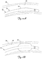
- FIGS. 2A and 2B are schematic views of the distal portion 36 of the lead 10 positioned in the branch vessel 30 according to an exemplary embodiment of the present invention.
- the inflatable member 55 can assume a deflated state ( FIG. 2A ) for delivery of the lead 10 to the desired implantation location. In the deflated state, the inflatable member 55 does not appreciably increase the outer diameter of the lead body 32 so as not to appreciably interfere with or impede transvenous delivery of the lead 10.
- the inflatable member 55 can be inflated so as to expand radially and impart a radial force on an interior surface 60 of the coronary branch vessel 30.
- the inflatable member 55 may, if desired, be subsequently deflated to remove the fixation force, according to the needs of the clinician.
- the clinician may determine that the lead 10 should be re-positioned in the same or different coronary vessel after its initial deployment.
- deflation of the inflatable member 55 may be effected to facilitate removal of the lead 10 from the patient.
- the inflatable member 55 may be used for delivery of the lead only, for example, to provide a temporary fixation and stabilization force during retraction of a guide wire or guide catheter from the patient.
- the degree of fixation i.e., the magnitude of the radial force imparted on the interior surface 60 by the inflatable member 55
- the inflatable member 55 advantageously provides a deployable fixation means that can be activated and deactivated as desired by the clinician.
- the inflatable member 55 may be positioned at any location on the distal portion 36. That is, the inflatable member 55 may be located at any location of the lead body 32 that will reside in the coronary sinus 18 or branch vessel 30 when the lead 10 is implanted.
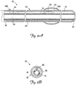
- FIG. 3A is a cross-sectional side view of the lead 10 according to one embodiment of the present invention
- FIG. 3B is a cross-sectional end view of the lead 10.
- the lead 10 includes an electrically conductive member 70 extending from the proximal end 35 toward the distal end 38, and the lead body 32 includes an inner surface 76.
- the conductive member 70 is in the form of an insulated wire coil.
- the lead body 32 provides an outer insulating layer 80, and the conductive member insulation forms an inner insulating layer 84 separated from the inner surface 76.
- the lead 10 further includes an inflation lumen 90 between the inner insulating layer 84 and the inner surface 76.
- the inflation lumen 90 is in the form of an elongate tubular member in fluid communication with the inflatable member 55, and operates to facilitate inflation of the inflatable member 55 using a suitable, biocompatible inflation media.
- the coiled conductive member 70 forms a primary lead lumen 94 which may facilitate lead delivery by receiving a stylet or guide wire as used in an over-the-wire delivery procedure.
- the lead 10 may include a non-coiled conductive member 70 (i.e., a cable).
- a separate lumen may be provided for lead delivery or other uses as deemed appropriate by the clinician.
- other lumens may be provided for any uses desired by the clinician.
- the lead 10 may include multiple conductive members, as are known for multi-electrode leads.
- the inflation lumen 90 is coupled to a portal 100 extending through the lead body 32 proximate the proximal end 35, and further extends through an orifice 106 in the lead body 32 to fluidly couple the portal 100 and the inflatable member 55.
- the inflatable member 55 can be inflated by introducing a fluid through the portal 100 until a desired degree of inflation of the inflatable member 55 is achieved.
- Fluid or other inflation medium can be introduced into the inflation lumen 90 through the portal 100 using a syringe, indeflator or other appropriate introducing means known to in the art.
- the portal 100 may include a sealing mechanism (e.g., a seal such as a hemostasis valve seal) adapted to permit introduction of the syringe, indeflator, or other fluid introduction means, yet substantially prevent loss of fluid through the portal 100 after inflation of the inflatable member 55.
- the portal 100 may be crimped or plugged to seal the portal 100 and prevent loss of inflation fluid there through.
- the portal 100 may be self-sealing to maintain the inflation fluid within the inflation lumen 90 and the inflatable member 55.
- the portal 100 may include a silicone plug. As is generally known, silicone tends to naturally seal itself upon being pierced. Other techniques and structures for sealing the portal 100 will be understood by those skilled in the art based on the foregoing.
- FIG. 4A is a cross-sectional side view of a lead 210 according to another embodiment of the present invention
- FIG. 4B is a cross-sectional end view of the lead 210.
- the lead 210 is overall similar to the lead 10, and includes a lead body 232 made of an electrically insulative material having a proximal end 235 and a distal end 238, and an inflatable member 255 on the lead body 232.
- the lead 210 includes an electrically conductive member 270 extending from the proximal end 235 toward the distal end 238, and the lead body 232 includes an inner surface 276.
- the lead 210 further includes a generally tubular, flexible inner insulating sheath 278 made of an electrically insulative material, e.g., polyurethane, disposed between the conductive member 270 and the inner surface 276 of the lead body 232.
- the lead body 232 provides an outer insulating layer 280, and the inner insulating sheath 278 forms an inner insulating layer separated from the inner surface 276 to define an inflation lumen 290 in fluid communication with the inflatable member 255.
- an electrically insulative coating over the coiled conductive member 290 forms the inner insulating layer.
- the annular inflation lumen 290 is configured to facilitate introduction of a fluid to inflate the inflatable member 255.
- the lead 210 further includes a portal 300 extending through the lead body 232 proximate the proximal end 235, and an orifice 306 extending through the lead body 232 to fluidly couple the inflatable member 255 and the inflation lumen 290.
- a fluid or other inflation medium can be introduced into the annular inflation lumen 290 using an syringe, indeflator or other appropriate introducing means known in the art through the portal 300, which may also include sealing features similar to those described above with respect to the lead 10.
- the lead 210 may include one or more optional spacer members 310 disposed between the inner insulation sheath 278 and the inner surface 276 of the lead body 232 to maintain separation there between, and thereby maintain the inflation lumen 290.
- the lead 210 may include multiple spacer members 310.
- elongated, circumferentially spaced ribs may be provided extending longitudinally along the inner surface 276 of the lead body 232 or the inner insulation sheath 278, which may operate to separate those structures and provide channels (i.e., the spaces between adjacent ribs) which operate as the inflation lumen 290.
- Other structures and techniques for maintaining separation between the inner insulation sheath 278 and the inner surface 276 of the lead body will be apparent to those skilled in the art based on the foregoing.
- the inflatable members 55, 255 described above may be made from any biocompatible or bio-absorbable material capable of maintaining sufficient hoop strength and burst pressure to provide fixation stability over a desired time duration and having sufficient softness to facilitate relatively unimpeded delivery of the respective lead.
- the inflatable members 55 and/or 255 may be made substantially or entirely of silicone rubber, polyurethane, or polyether block amide.
- the inflatable member is a silicone rubber membrane adhesively bonded to the outer surface of the lead body.
- the inflatable member may be made from a semi-porous material selected to permit a controlled release of the inflation medium so as to allow deflation of the inflatable member over time.
- the inflatable member may be desirable for the inflatable member to supply a fixation force only for a limited duration, e.g., until tissue ingrowth and fibrosis takes over as the primary fixation mechanism.
- the inflatable member may be made from a semi-porous material configured to allow diffusion of the inflation medium into the bloodstream such that the inflatable member no longer provides a fixation force after, for example, two to four weeks.
- a similar result can be achieved by making the inflatable member from a bio-absorbable material, as is known in the art.
- the insulating materials may be made from any electrically insulative materials suitable for transvenously deployed cardiac leads, whether now known or later developed.
- the lead bodies 32, 232 and the inner insulating layer i.e., the inner insulating layer 84 and the insulating sheath 278) are made substantially from polyurethane.
- the inflatable members 55, 255 described above may be incorporated into any medical electrical leads sized and shaped for use in left ventricular stimulation.
- the lumen designs of the leads 10, 210 may facilitate incorporation of the inflatable members 55, 255 into smaller diameter lead sizes as compared to prior leads with inflatable balloon structures wherein the inflation lumen(s) were disposed within the thickness of the outer insulating layer of the lead body. That is, disposing the inflation lumen within the thickness of the lead body outer layer may require increasing the overall thickness of that layer, which in turn, results in a relatively larger diameter lead. Additionally, increasing the thickness of the outer insulating layer to accommodate the inflation lumen may increase the overall stiffness of the lead, which may in turn adversely affect transvenous delivery of the lead. In short, the inflation lumen configurations of the leads 10, 210 of the present invention may be better suited for left side leads which must be delivered through potentially tortuous venous anatomies.
- the inflatable members 55, 255 described herein may be inflated using any biocompatible fluid, including without limitation, air, a saline solution, or any other biocompatible gas or liquid media.
- FIGS. 5A and 5B illustrate portions of leads 410, 412 respectively, according to yet additional embodiments of the present invention.
- the leads 410, 412 can in many respects be substantially the same as or identical to any of the leads described above, the exceptions being in the inflatable member configurations.
- the lead 410 includes an inflatable member 455 that extends only partially around the lead body. In one embodiment, for example, the inflatable member 455 extends between about 90° and about 270° about the lead body. By the illustrated configuration, when inflated, the inflatable member 455 can advantageously cause the lead electrode to be biased toward the inner surface 60 of the target branch vessel 30 in which the distal end of the lead 410 is implanted.
- the inflatable member 455 operates to secure the lead 410 in place and also to improve electrode contact with the vessel tissue.
- the lead 412 includes an inflatable member 455 that is disposed about the lead body in a generally helical configuration. It will be appreciated that other inflatable member shapes and configurations may be utilized within the scope of the present invention.
- the respective leads include a single inflatable fixation member, e.g., the inflatable members 55, 255, and 455.
- a plurality of inflatable members are provided.
- the lead may include two or more inflatable members located along the lead body such that they will be positioned in the target branch vessel in which the lead distal end is implanted.
- the lead may include one inflatable member at a location such that it can be positioned in the target branch vessel, and another inflatable member positioned in the coronary sinus 18 (see FIG. 1 ).
- the inflatable member positioned in the coronary sinus 18 may provide enhanced stability and fixation strength during the implantation procedure (e.g., as during retraction of the guide wire in an over-the-wire implantation, as is known).
- Other combinations of inflatable fixation members will be understood by those skilled in the art based on the foregoing.
Landscapes
- Health & Medical Sciences (AREA)
- Heart & Thoracic Surgery (AREA)
- Life Sciences & Earth Sciences (AREA)
- Public Health (AREA)
- Veterinary Medicine (AREA)
- Cardiology (AREA)
- Engineering & Computer Science (AREA)
- General Health & Medical Sciences (AREA)
- Biomedical Technology (AREA)
- Animal Behavior & Ethology (AREA)
- Hematology (AREA)
- Anesthesiology (AREA)
- Child & Adolescent Psychology (AREA)
- Biophysics (AREA)
- Pulmonology (AREA)
- Vascular Medicine (AREA)
- Nuclear Medicine, Radiotherapy & Molecular Imaging (AREA)
- Radiology & Medical Imaging (AREA)
- Electrotherapy Devices (AREA)
Applications Claiming Priority (2)
| Application Number | Priority Date | Filing Date | Title |
|---|---|---|---|
| US11/622,810 US7765015B2 (en) | 2007-01-12 | 2007-01-12 | Lead with inflatable fixation mechanism |
| PCT/US2008/050455 WO2008088967A1 (en) | 2007-01-12 | 2008-01-08 | Lead with inflatable fixation mechanism |
Publications (2)
| Publication Number | Publication Date |
|---|---|
| EP2117637A1 EP2117637A1 (en) | 2009-11-18 |
| EP2117637B1 true EP2117637B1 (en) | 2017-03-01 |
Family
ID=39301181
Family Applications (1)
| Application Number | Title | Priority Date | Filing Date |
|---|---|---|---|
| EP08705760.0A Not-in-force EP2117637B1 (en) | 2007-01-12 | 2008-01-08 | Lead with inflatable fixation mechanism |
Country Status (4)
| Country | Link |
|---|---|
| US (1) | US7765015B2 (enExample) |
| EP (1) | EP2117637B1 (enExample) |
| JP (1) | JP2010515537A (enExample) |
| WO (1) | WO2008088967A1 (enExample) |
Families Citing this family (34)
| Publication number | Priority date | Publication date | Assignee | Title |
|---|---|---|---|---|
| US8406901B2 (en) * | 2006-04-27 | 2013-03-26 | Medtronic, Inc. | Sutureless implantable medical device fixation |
| US9492657B2 (en) * | 2006-11-30 | 2016-11-15 | Medtronic, Inc. | Method of implanting a medical device including a fixation element |
| US8343029B2 (en) * | 2007-10-24 | 2013-01-01 | Circulite, Inc. | Transseptal cannula, tip, delivery system, and method |
| US8460168B2 (en) | 2009-03-27 | 2013-06-11 | Circulite, Inc. | Transseptal cannula device, coaxial balloon delivery device, and methods of using the same |
| US8478423B2 (en) * | 2009-04-07 | 2013-07-02 | Boston Scientific Neuromodulation Corporation | Insulator layers for leads of implantable electric stimulation systems and methods of making and using |
| CA2768567C (en) | 2009-09-14 | 2017-03-21 | Circulite, Inc. | Endovascular anastomotic connector device, delivery system, and methods of delivery and use |
| US9872981B2 (en) | 2010-09-28 | 2018-01-23 | Biotrace Medical, Inc. | Device and method for positioning an electrode in a body cavity |
| US9855421B2 (en) * | 2010-09-28 | 2018-01-02 | The Board Of Trustees Of The Leland Stanford Junior University | Device and method for positioning an electrode in tissue |
| US10112045B2 (en) | 2010-12-29 | 2018-10-30 | Medtronic, Inc. | Implantable medical device fixation |
| US9775982B2 (en) | 2010-12-29 | 2017-10-03 | Medtronic, Inc. | Implantable medical device fixation |
| EP2723435A4 (en) * | 2011-06-24 | 2015-03-04 | Accessclosure Inc | METHOD AND DEVICES FOR FLOW OCCLUSION DURING DEVICE EXCHANGES |
| US10434292B2 (en) * | 2011-06-24 | 2019-10-08 | Access Closure | Method and devices for flow occlusion during device exchanges |
| US20130158640A1 (en) * | 2011-12-19 | 2013-06-20 | Brian D. Soltis | Lead anchoring system with limited movement of anchoring device along lead |
| US9339197B2 (en) | 2012-03-26 | 2016-05-17 | Medtronic, Inc. | Intravascular implantable medical device introduction |
| US9717421B2 (en) | 2012-03-26 | 2017-08-01 | Medtronic, Inc. | Implantable medical device delivery catheter with tether |
| US9220906B2 (en) | 2012-03-26 | 2015-12-29 | Medtronic, Inc. | Tethered implantable medical device deployment |
| US9854982B2 (en) | 2012-03-26 | 2018-01-02 | Medtronic, Inc. | Implantable medical device deployment within a vessel |
| US10485435B2 (en) | 2012-03-26 | 2019-11-26 | Medtronic, Inc. | Pass-through implantable medical device delivery catheter with removeable distal tip |
| US9833625B2 (en) | 2012-03-26 | 2017-12-05 | Medtronic, Inc. | Implantable medical device delivery with inner and outer sheaths |
| US9532785B2 (en) | 2012-05-09 | 2017-01-03 | Access Closure, Inc. | Method and devices for flow occlusion during device exchanges |
| US9351648B2 (en) | 2012-08-24 | 2016-05-31 | Medtronic, Inc. | Implantable medical device electrode assembly |
| WO2014070680A1 (en) | 2012-10-29 | 2014-05-08 | Cardiac Pacemakers, Inc. | Suture sleeves having exterior surface tear resistance |
| US9486622B2 (en) | 2012-11-08 | 2016-11-08 | Cardiac Pacemakers, Inc. | Fixation and strain relief element for temporary therapy delivery device |
| JP6697393B2 (ja) | 2013-11-25 | 2020-05-20 | カスタム メディカル アプリケーションズ インク.Custom Medical Applications, Inc. | アンカーエレメント、一つ以上のアンカーエレメントと関連アセンブリとを含む医療装置、及び方法 |
| CN106659880B (zh) | 2014-05-09 | 2019-06-18 | 比奥特雷斯医疗公司 | 用于在体腔中定位电极的装置和方法 |
| WO2016187473A1 (en) | 2015-05-20 | 2016-11-24 | Cardiac Pacemakers, Inc. | Fully integrated lead stabilizer for medical electrical leads and methods of attachment |
| CA2998368C (en) | 2015-09-15 | 2024-03-26 | Custom Medical Applications Inc. | Deployment devices and related assemblies and methods |
| CN108348756B (zh) | 2015-11-20 | 2021-10-22 | 心脏起搏器股份公司 | 用于多腔室感测和起搏的单通道冠状静脉导线 |
| EP3491047B1 (en) | 2016-07-28 | 2021-09-15 | 3M Innovative Properties Company | Segmented silicone polyamide block copolymers and articles containing the same |
| JP2019529596A (ja) | 2016-07-28 | 2019-10-17 | スリーエム イノベイティブ プロパティズ カンパニー | セグメント化シリコーンポリアミドブロックコポリマー及びそれを含む物品 |
| US10874850B2 (en) | 2018-09-28 | 2020-12-29 | Medtronic, Inc. | Impedance-based verification for delivery of implantable medical devices |
| US11331475B2 (en) | 2019-05-07 | 2022-05-17 | Medtronic, Inc. | Tether assemblies for medical device delivery systems |
| US12151100B2 (en) | 2019-05-07 | 2024-11-26 | Medtronic, Inc. | Tether assemblies for medical device delivery systems |
| US12472369B2 (en) | 2021-12-20 | 2025-11-18 | Medtronic, Inc. | Implantable medical lead shield |
Citations (1)
| Publication number | Priority date | Publication date | Assignee | Title |
|---|---|---|---|---|
| US20030074039A1 (en) * | 1999-06-25 | 2003-04-17 | Puskas John D. | Devices and methods for vagus nerve stimulation |
Family Cites Families (32)
| Publication number | Priority date | Publication date | Assignee | Title |
|---|---|---|---|---|
| DE2305262A1 (de) * | 1973-02-02 | 1974-08-08 | Siemens Ag | Endocardelektrode |
| US4559951A (en) * | 1982-11-29 | 1985-12-24 | Cardiac Pacemakers, Inc. | Catheter assembly |
| US4519403A (en) * | 1983-04-29 | 1985-05-28 | Medtronic, Inc. | Balloon lead and inflator |
| US4531943A (en) * | 1983-08-08 | 1985-07-30 | Angiomedics Corporation | Catheter with soft deformable tip |
| US4551292A (en) * | 1984-04-05 | 1985-11-05 | Angiomedics, Inc. | Method for making a catheter with a soft, deformable tip |
| US4706682A (en) * | 1985-08-21 | 1987-11-17 | Minnesota Mining And Manufacturing Company | External ear canal electrode to be placed proximate the tympanic membrane |
| US4863442A (en) * | 1987-08-14 | 1989-09-05 | C. R. Bard, Inc. | Soft tip catheter |
| US5025786A (en) * | 1988-07-21 | 1991-06-25 | Siegel Sharon B | Intracardiac catheter and method for detecting and diagnosing myocardial ischemia |
| US5087244A (en) * | 1989-01-31 | 1992-02-11 | C. R. Bard, Inc. | Catheter and method for locally applying medication to the wall of a blood vessel or other body lumen |
| CA2081896A1 (en) | 1990-06-15 | 1991-12-16 | James E. Shapland | Drug delivery apparatus and method |
| US5205292A (en) * | 1991-06-03 | 1993-04-27 | Applied Biometric, Inc. | Removable implanted device |
| US5571159A (en) * | 1994-04-04 | 1996-11-05 | Alt; Eckhard | Temporary atrial defibrillation catheter and method |
| US5855546A (en) | 1996-02-29 | 1999-01-05 | Sci-Med Life Systems | Perfusion balloon and radioactive wire delivery system |
| US6108706A (en) * | 1997-06-09 | 2000-08-22 | Microsoft Corporation | Transmission announcement system and method for announcing upcoming data transmissions over a broadcast network |
| US5991668A (en) * | 1997-09-25 | 1999-11-23 | Medtronic, Inc. | Medical electrical lead |
| US5925073A (en) * | 1998-02-23 | 1999-07-20 | Cardiac Pacemakers, Inc. | Intravenous cardiac lead with wave shaped fixation segment |
| US5951597A (en) * | 1998-04-14 | 1999-09-14 | Cardiac Pacemakers, Inc. | Coronary sinus lead having expandable matrix anchor |
| SE9802104D0 (sv) * | 1998-06-12 | 1998-06-12 | Pacesetter Ab | Medical electrode device |
| FR2784300B1 (fr) * | 1998-10-13 | 2000-12-08 | Ela Medical Sa | Sonde de stimulation du ventricule gauche implantable dans le reseau veineux coronarien pour dispositif medical implantable actif, notamment stimulateur de type "multisite" |
| US7313444B2 (en) * | 1998-11-20 | 2007-12-25 | Pacesetter, Inc. | Self-anchoring coronary sinus lead |
| US6136021A (en) * | 1999-03-23 | 2000-10-24 | Cardiac Pacemakers, Inc. | Expandable electrode for coronary venous leads |
| US6556873B1 (en) * | 1999-11-29 | 2003-04-29 | Medtronic, Inc. | Medical electrical lead having variable bending stiffness |
| US6510348B2 (en) * | 2000-12-20 | 2003-01-21 | Medtronic, Inc. | Perfusion lead and method of use |
| US6567704B2 (en) | 2000-12-20 | 2003-05-20 | Medtronic, Inc. | Medical electrical lead and method of use |
| US7099718B1 (en) * | 2001-05-29 | 2006-08-29 | Advanced Bionics Corporation | Neural stimulation lead fixation |
| US6968237B2 (en) * | 2002-05-22 | 2005-11-22 | Pacesetter, Inc. | Implantable coronary sinus lead and lead system |
| US7107105B2 (en) | 2002-09-24 | 2006-09-12 | Medtronic, Inc. | Deployable medical lead fixation system and method |
| US7228356B2 (en) * | 2002-12-12 | 2007-06-05 | Alcatel Canada Inc. | IGMP expedited leave triggered by MAC address |
| US20040230282A1 (en) * | 2003-04-11 | 2004-11-18 | Cates Adam W. | Acute and chronic fixation for subcutaneous electrodes |
| US20040243210A1 (en) * | 2003-05-30 | 2004-12-02 | Morgan Kevin L. | Fixation of a left heart medical lead in the coronary sinus |
| US7499757B2 (en) * | 2003-10-24 | 2009-03-03 | Cardiac Pacemakers, Inc. | Absorbable myocardial lead fixation system |
| US20060089694A1 (en) * | 2004-10-21 | 2006-04-27 | Cardiac Pacemakers, Inc. | Delivery system and method for pulmonary artery leads |
-
2007
- 2007-01-12 US US11/622,810 patent/US7765015B2/en not_active Expired - Fee Related
-
2008
- 2008-01-08 WO PCT/US2008/050455 patent/WO2008088967A1/en not_active Ceased
- 2008-01-08 JP JP2009545629A patent/JP2010515537A/ja active Pending
- 2008-01-08 EP EP08705760.0A patent/EP2117637B1/en not_active Not-in-force
Patent Citations (1)
| Publication number | Priority date | Publication date | Assignee | Title |
|---|---|---|---|---|
| US20030074039A1 (en) * | 1999-06-25 | 2003-04-17 | Puskas John D. | Devices and methods for vagus nerve stimulation |
Also Published As
| Publication number | Publication date |
|---|---|
| US7765015B2 (en) | 2010-07-27 |
| EP2117637A1 (en) | 2009-11-18 |
| US20080172118A1 (en) | 2008-07-17 |
| JP2010515537A (ja) | 2010-05-13 |
| WO2008088967A1 (en) | 2008-07-24 |
Similar Documents
| Publication | Publication Date | Title |
|---|---|---|
| EP2117637B1 (en) | Lead with inflatable fixation mechanism | |
| US10980570B2 (en) | Implantation of an active medical device using the internal thoracic vasculature | |
| US12268877B2 (en) | Transvascular nerve stimulation apparatus and methods | |
| US10537731B2 (en) | Transvenous mediastinum access for the placement of cardiac pacing and defibrillation electrodes | |
| US20180133463A1 (en) | Electrode for sensing, pacing, and defibrillation deployable in the mediastinal space | |
| US10850067B2 (en) | Implantation of an active medical device using the intercostal vein | |
| US10786679B2 (en) | Lead with integrated electrodes | |
| US6567704B2 (en) | Medical electrical lead and method of use | |
| US6574512B1 (en) | Lead system with main lead and transverse lead | |
| US11020075B2 (en) | Implantation of an active medical device using the internal thoracic vasculature | |
| EP1545688A2 (en) | Medical device delivery system | |
| US20090192579A1 (en) | Implantation methods, systems and tools for intravascular implantable devices | |
| US20030083725A1 (en) | Method and apparatus for endovenous pacing lead | |
| EP0959940B1 (en) | Lead introducer with defibrillation electrode for atrial defibrillation |
Legal Events
| Date | Code | Title | Description |
|---|---|---|---|
| PUAI | Public reference made under article 153(3) epc to a published international application that has entered the european phase |
Free format text: ORIGINAL CODE: 0009012 |
|
| 17P | Request for examination filed |
Effective date: 20090713 |
|
| AK | Designated contracting states |
Kind code of ref document: A1 Designated state(s): AT BE BG CH CY CZ DE DK EE ES FI FR GB GR HR HU IE IS IT LI LT LU LV MC MT NL NO PL PT RO SE SI SK TR |
|
| 17Q | First examination report despatched |
Effective date: 20100311 |
|
| DAX | Request for extension of the european patent (deleted) | ||
| RIC1 | Information provided on ipc code assigned before grant |
Ipc: A61M 25/10 20060101ALI20160705BHEP Ipc: A61N 1/05 20060101AFI20160705BHEP Ipc: A61M 25/04 20060101ALI20160705BHEP |
|
| GRAP | Despatch of communication of intention to grant a patent |
Free format text: ORIGINAL CODE: EPIDOSNIGR1 |
|
| INTG | Intention to grant announced |
Effective date: 20160826 |
|
| GRAS | Grant fee paid |
Free format text: ORIGINAL CODE: EPIDOSNIGR3 |
|
| GRAA | (expected) grant |
Free format text: ORIGINAL CODE: 0009210 |
|
| AK | Designated contracting states |
Kind code of ref document: B1 Designated state(s): AT BE BG CH CY CZ DE DK EE ES FI FR GB GR HR HU IE IS IT LI LT LU LV MC MT NL NO PL PT RO SE SI SK TR |
|
| REG | Reference to a national code |
Ref country code: GB Ref legal event code: FG4D |
|
| REG | Reference to a national code |
Ref country code: CH Ref legal event code: EP Ref country code: AT Ref legal event code: REF Ref document number: 870568 Country of ref document: AT Kind code of ref document: T Effective date: 20170315 |
|
| REG | Reference to a national code |
Ref country code: IE Ref legal event code: FG4D |
|
| REG | Reference to a national code |
Ref country code: DE Ref legal event code: R096 Ref document number: 602008048926 Country of ref document: DE |
|
| REG | Reference to a national code |
Ref country code: NL Ref legal event code: MP Effective date: 20170301 |
|
| REG | Reference to a national code |
Ref country code: LT Ref legal event code: MG4D |
|
| REG | Reference to a national code |
Ref country code: AT Ref legal event code: MK05 Ref document number: 870568 Country of ref document: AT Kind code of ref document: T Effective date: 20170301 |
|
| PG25 | Lapsed in a contracting state [announced via postgrant information from national office to epo] |
Ref country code: HR Free format text: LAPSE BECAUSE OF FAILURE TO SUBMIT A TRANSLATION OF THE DESCRIPTION OR TO PAY THE FEE WITHIN THE PRESCRIBED TIME-LIMIT Effective date: 20170301 Ref country code: LT Free format text: LAPSE BECAUSE OF FAILURE TO SUBMIT A TRANSLATION OF THE DESCRIPTION OR TO PAY THE FEE WITHIN THE PRESCRIBED TIME-LIMIT Effective date: 20170301 Ref country code: FI Free format text: LAPSE BECAUSE OF FAILURE TO SUBMIT A TRANSLATION OF THE DESCRIPTION OR TO PAY THE FEE WITHIN THE PRESCRIBED TIME-LIMIT Effective date: 20170301 Ref country code: NO Free format text: LAPSE BECAUSE OF FAILURE TO SUBMIT A TRANSLATION OF THE DESCRIPTION OR TO PAY THE FEE WITHIN THE PRESCRIBED TIME-LIMIT Effective date: 20170601 Ref country code: GR Free format text: LAPSE BECAUSE OF FAILURE TO SUBMIT A TRANSLATION OF THE DESCRIPTION OR TO PAY THE FEE WITHIN THE PRESCRIBED TIME-LIMIT Effective date: 20170602 |
|
| PG25 | Lapsed in a contracting state [announced via postgrant information from national office to epo] |
Ref country code: LV Free format text: LAPSE BECAUSE OF FAILURE TO SUBMIT A TRANSLATION OF THE DESCRIPTION OR TO PAY THE FEE WITHIN THE PRESCRIBED TIME-LIMIT Effective date: 20170301 Ref country code: BG Free format text: LAPSE BECAUSE OF FAILURE TO SUBMIT A TRANSLATION OF THE DESCRIPTION OR TO PAY THE FEE WITHIN THE PRESCRIBED TIME-LIMIT Effective date: 20170601 Ref country code: AT Free format text: LAPSE BECAUSE OF FAILURE TO SUBMIT A TRANSLATION OF THE DESCRIPTION OR TO PAY THE FEE WITHIN THE PRESCRIBED TIME-LIMIT Effective date: 20170301 Ref country code: ES Free format text: LAPSE BECAUSE OF FAILURE TO SUBMIT A TRANSLATION OF THE DESCRIPTION OR TO PAY THE FEE WITHIN THE PRESCRIBED TIME-LIMIT Effective date: 20170301 Ref country code: SE Free format text: LAPSE BECAUSE OF FAILURE TO SUBMIT A TRANSLATION OF THE DESCRIPTION OR TO PAY THE FEE WITHIN THE PRESCRIBED TIME-LIMIT Effective date: 20170301 |
|
| PG25 | Lapsed in a contracting state [announced via postgrant information from national office to epo] |
Ref country code: NL Free format text: LAPSE BECAUSE OF FAILURE TO SUBMIT A TRANSLATION OF THE DESCRIPTION OR TO PAY THE FEE WITHIN THE PRESCRIBED TIME-LIMIT Effective date: 20170301 |
|
| PG25 | Lapsed in a contracting state [announced via postgrant information from national office to epo] |
Ref country code: SK Free format text: LAPSE BECAUSE OF FAILURE TO SUBMIT A TRANSLATION OF THE DESCRIPTION OR TO PAY THE FEE WITHIN THE PRESCRIBED TIME-LIMIT Effective date: 20170301 Ref country code: EE Free format text: LAPSE BECAUSE OF FAILURE TO SUBMIT A TRANSLATION OF THE DESCRIPTION OR TO PAY THE FEE WITHIN THE PRESCRIBED TIME-LIMIT Effective date: 20170301 Ref country code: RO Free format text: LAPSE BECAUSE OF FAILURE TO SUBMIT A TRANSLATION OF THE DESCRIPTION OR TO PAY THE FEE WITHIN THE PRESCRIBED TIME-LIMIT Effective date: 20170301 Ref country code: CZ Free format text: LAPSE BECAUSE OF FAILURE TO SUBMIT A TRANSLATION OF THE DESCRIPTION OR TO PAY THE FEE WITHIN THE PRESCRIBED TIME-LIMIT Effective date: 20170301 |
|
| PG25 | Lapsed in a contracting state [announced via postgrant information from national office to epo] |
Ref country code: PT Free format text: LAPSE BECAUSE OF FAILURE TO SUBMIT A TRANSLATION OF THE DESCRIPTION OR TO PAY THE FEE WITHIN THE PRESCRIBED TIME-LIMIT Effective date: 20170703 Ref country code: PL Free format text: LAPSE BECAUSE OF FAILURE TO SUBMIT A TRANSLATION OF THE DESCRIPTION OR TO PAY THE FEE WITHIN THE PRESCRIBED TIME-LIMIT Effective date: 20170301 Ref country code: IS Free format text: LAPSE BECAUSE OF FAILURE TO SUBMIT A TRANSLATION OF THE DESCRIPTION OR TO PAY THE FEE WITHIN THE PRESCRIBED TIME-LIMIT Effective date: 20170701 |
|
| REG | Reference to a national code |
Ref country code: DE Ref legal event code: R097 Ref document number: 602008048926 Country of ref document: DE |
|
| REG | Reference to a national code |
Ref country code: FR Ref legal event code: PLFP Year of fee payment: 11 |
|
| PLBE | No opposition filed within time limit |
Free format text: ORIGINAL CODE: 0009261 |
|
| STAA | Information on the status of an ep patent application or granted ep patent |
Free format text: STATUS: NO OPPOSITION FILED WITHIN TIME LIMIT |
|
| PG25 | Lapsed in a contracting state [announced via postgrant information from national office to epo] |
Ref country code: DK Free format text: LAPSE BECAUSE OF FAILURE TO SUBMIT A TRANSLATION OF THE DESCRIPTION OR TO PAY THE FEE WITHIN THE PRESCRIBED TIME-LIMIT Effective date: 20170301 |
|
| PGFP | Annual fee paid to national office [announced via postgrant information from national office to epo] |
Ref country code: FR Payment date: 20171211 Year of fee payment: 11 |
|
| 26N | No opposition filed |
Effective date: 20171204 |
|
| PG25 | Lapsed in a contracting state [announced via postgrant information from national office to epo] |
Ref country code: SI Free format text: LAPSE BECAUSE OF FAILURE TO SUBMIT A TRANSLATION OF THE DESCRIPTION OR TO PAY THE FEE WITHIN THE PRESCRIBED TIME-LIMIT Effective date: 20170301 Ref country code: IT Free format text: LAPSE BECAUSE OF FAILURE TO SUBMIT A TRANSLATION OF THE DESCRIPTION OR TO PAY THE FEE WITHIN THE PRESCRIBED TIME-LIMIT Effective date: 20170301 |
|
| PGFP | Annual fee paid to national office [announced via postgrant information from national office to epo] |
Ref country code: NL Payment date: 20180115 Year of fee payment: 11 |
|
| PGFP | Annual fee paid to national office [announced via postgrant information from national office to epo] |
Ref country code: DE Payment date: 20171228 Year of fee payment: 11 Ref country code: GB Payment date: 20180103 Year of fee payment: 11 |
|
| REG | Reference to a national code |
Ref country code: CH Ref legal event code: PL |
|
| PG25 | Lapsed in a contracting state [announced via postgrant information from national office to epo] |
Ref country code: LU Free format text: LAPSE BECAUSE OF NON-PAYMENT OF DUE FEES Effective date: 20180108 |
|
| REG | Reference to a national code |
Ref country code: IE Ref legal event code: MM4A |
|
| REG | Reference to a national code |
Ref country code: BE Ref legal event code: MM Effective date: 20180131 |
|
| PG25 | Lapsed in a contracting state [announced via postgrant information from national office to epo] |
Ref country code: BE Free format text: LAPSE BECAUSE OF NON-PAYMENT OF DUE FEES Effective date: 20180131 Ref country code: CH Free format text: LAPSE BECAUSE OF NON-PAYMENT OF DUE FEES Effective date: 20180131 Ref country code: LI Free format text: LAPSE BECAUSE OF NON-PAYMENT OF DUE FEES Effective date: 20180131 |
|
| PG25 | Lapsed in a contracting state [announced via postgrant information from national office to epo] |
Ref country code: IE Free format text: LAPSE BECAUSE OF NON-PAYMENT OF DUE FEES Effective date: 20180108 |
|
| PG25 | Lapsed in a contracting state [announced via postgrant information from national office to epo] |
Ref country code: MC Free format text: LAPSE BECAUSE OF FAILURE TO SUBMIT A TRANSLATION OF THE DESCRIPTION OR TO PAY THE FEE WITHIN THE PRESCRIBED TIME-LIMIT Effective date: 20170301 |
|
| REG | Reference to a national code |
Ref country code: DE Ref legal event code: R119 Ref document number: 602008048926 Country of ref document: DE |
|
| GBPC | Gb: european patent ceased through non-payment of renewal fee |
Effective date: 20190108 |
|
| PG25 | Lapsed in a contracting state [announced via postgrant information from national office to epo] |
Ref country code: FR Free format text: LAPSE BECAUSE OF NON-PAYMENT OF DUE FEES Effective date: 20190131 Ref country code: DE Free format text: LAPSE BECAUSE OF NON-PAYMENT OF DUE FEES Effective date: 20190801 |
|
| PG25 | Lapsed in a contracting state [announced via postgrant information from national office to epo] |
Ref country code: GB Free format text: LAPSE BECAUSE OF NON-PAYMENT OF DUE FEES Effective date: 20190108 |
|
| PG25 | Lapsed in a contracting state [announced via postgrant information from national office to epo] |
Ref country code: MT Free format text: LAPSE BECAUSE OF NON-PAYMENT OF DUE FEES Effective date: 20180108 |
|
| PG25 | Lapsed in a contracting state [announced via postgrant information from national office to epo] |
Ref country code: TR Free format text: LAPSE BECAUSE OF FAILURE TO SUBMIT A TRANSLATION OF THE DESCRIPTION OR TO PAY THE FEE WITHIN THE PRESCRIBED TIME-LIMIT Effective date: 20170301 |
|
| PG25 | Lapsed in a contracting state [announced via postgrant information from national office to epo] |
Ref country code: HU Free format text: LAPSE BECAUSE OF FAILURE TO SUBMIT A TRANSLATION OF THE DESCRIPTION OR TO PAY THE FEE WITHIN THE PRESCRIBED TIME-LIMIT; INVALID AB INITIO Effective date: 20080108 |
|
| PG25 | Lapsed in a contracting state [announced via postgrant information from national office to epo] |
Ref country code: CY Free format text: LAPSE BECAUSE OF FAILURE TO SUBMIT A TRANSLATION OF THE DESCRIPTION OR TO PAY THE FEE WITHIN THE PRESCRIBED TIME-LIMIT Effective date: 20170301 |