EP2116831A1 - Temperature sensor - Google Patents
Temperature sensor Download PDFInfo
- Publication number
- EP2116831A1 EP2116831A1 EP20090006344 EP09006344A EP2116831A1 EP 2116831 A1 EP2116831 A1 EP 2116831A1 EP 20090006344 EP20090006344 EP 20090006344 EP 09006344 A EP09006344 A EP 09006344A EP 2116831 A1 EP2116831 A1 EP 2116831A1
- Authority
- EP
- European Patent Office
- Prior art keywords
- inner tube
- temperature sensor
- junction
- tube
- sheath
- Prior art date
- Legal status (The legal status is an assumption and is not a legal conclusion. Google has not performed a legal analysis and makes no representation as to the accuracy of the status listed.)
- Granted
Links
- 239000011810 insulating material Substances 0.000 claims abstract description 12
- 229910052751 metal Inorganic materials 0.000 claims description 16
- 239000002184 metal Substances 0.000 claims description 16
- 238000003466 welding Methods 0.000 claims description 11
- 238000000034 method Methods 0.000 claims description 8
- 238000004519 manufacturing process Methods 0.000 claims 1
- 230000008602 contraction Effects 0.000 description 15
- 230000035882 stress Effects 0.000 description 15
- 239000007789 gas Substances 0.000 description 14
- 238000001816 cooling Methods 0.000 description 8
- 238000002788 crimping Methods 0.000 description 7
- 239000004568 cement Substances 0.000 description 5
- 238000005382 thermal cycling Methods 0.000 description 5
- VYPSYNLAJGMNEJ-UHFFFAOYSA-N Silicium dioxide Chemical compound O=[Si]=O VYPSYNLAJGMNEJ-UHFFFAOYSA-N 0.000 description 4
- 230000002708 enhancing effect Effects 0.000 description 4
- 230000001965 increasing effect Effects 0.000 description 4
- 230000004043 responsiveness Effects 0.000 description 4
- 230000000717 retained effect Effects 0.000 description 4
- PNEYBMLMFCGWSK-UHFFFAOYSA-N aluminium oxide Inorganic materials [O-2].[O-2].[O-2].[Al+3].[Al+3] PNEYBMLMFCGWSK-UHFFFAOYSA-N 0.000 description 3
- 238000009529 body temperature measurement Methods 0.000 description 3
- 230000000694 effects Effects 0.000 description 3
- 229910018967 Pt—Rh Inorganic materials 0.000 description 2
- 230000003247 decreasing effect Effects 0.000 description 2
- 230000007547 defect Effects 0.000 description 2
- 238000005259 measurement Methods 0.000 description 2
- 239000000377 silicon dioxide Substances 0.000 description 2
- 230000008646 thermal stress Effects 0.000 description 2
- 239000000919 ceramic Substances 0.000 description 1
- 229910052681 coesite Inorganic materials 0.000 description 1
- 239000000470 constituent Substances 0.000 description 1
- 229910052906 cristobalite Inorganic materials 0.000 description 1
- 230000002542 deteriorative effect Effects 0.000 description 1
- 238000010438 heat treatment Methods 0.000 description 1
- 239000003779 heat-resistant material Substances 0.000 description 1
- 239000011261 inert gas Substances 0.000 description 1
- 238000003780 insertion Methods 0.000 description 1
- 230000037431 insertion Effects 0.000 description 1
- 239000000463 material Substances 0.000 description 1
- 239000000203 mixture Substances 0.000 description 1
- 238000003825 pressing Methods 0.000 description 1
- 238000007789 sealing Methods 0.000 description 1
- 229910001220 stainless steel Inorganic materials 0.000 description 1
- 239000010935 stainless steel Substances 0.000 description 1
- 229910052682 stishovite Inorganic materials 0.000 description 1
- 238000010408 sweeping Methods 0.000 description 1
- 229910052905 tridymite Inorganic materials 0.000 description 1
- WFKWXMTUELFFGS-UHFFFAOYSA-N tungsten Chemical compound [W] WFKWXMTUELFFGS-UHFFFAOYSA-N 0.000 description 1
- 229910052721 tungsten Inorganic materials 0.000 description 1
- 239000010937 tungsten Substances 0.000 description 1
Images


Classifications
-
- G—PHYSICS
- G01—MEASURING; TESTING
- G01K—MEASURING TEMPERATURE; MEASURING QUANTITY OF HEAT; THERMALLY-SENSITIVE ELEMENTS NOT OTHERWISE PROVIDED FOR
- G01K1/00—Details of thermometers not specially adapted for particular types of thermometer
- G01K1/08—Protective devices, e.g. casings
- G01K1/12—Protective devices, e.g. casings for preventing damage due to heat overloading
-
- G—PHYSICS
- G01—MEASURING; TESTING
- G01K—MEASURING TEMPERATURE; MEASURING QUANTITY OF HEAT; THERMALLY-SENSITIVE ELEMENTS NOT OTHERWISE PROVIDED FOR
- G01K13/00—Thermometers specially adapted for specific purposes
- G01K13/02—Thermometers specially adapted for specific purposes for measuring temperature of moving fluids or granular materials capable of flow
-
- G—PHYSICS
- G01—MEASURING; TESTING
- G01K—MEASURING TEMPERATURE; MEASURING QUANTITY OF HEAT; THERMALLY-SENSITIVE ELEMENTS NOT OTHERWISE PROVIDED FOR
- G01K2205/00—Application of thermometers in motors, e.g. of a vehicle
- G01K2205/04—Application of thermometers in motors, e.g. of a vehicle for measuring exhaust gas temperature
Landscapes
- Physics & Mathematics (AREA)
- General Physics & Mathematics (AREA)
- Measuring Temperature Or Quantity Of Heat (AREA)
Abstract
Description
- The present invention relates to a temperature sensor having a temperature sensing element such as a thermistor and a Pt resistance thermometer.
- As a temperature sensor for detecting the temperature of exhaust gas of a vehicle or the like, a thermistor, a Pt resistance thermometer, or the like which exhibits a change in resistance with changing temperature has been known (refer to
Patent Documents 1 and 2). - A configuration of this type of temperature sensor is illustrated in
Fig. 6 . As illustrated in the upper cross section ofFig. 6 ,temperature sensor 500 is configured by welding and accommodating athermistor 502 and asheath member 506 in ametal tube 512, and filling themetal tube 512 with acement 514 such as alumina through a gap in themetal tube 512. - The
thermistor 502 includes a thermistor sinteredbody 503 and adevice electrode wire 504. Since thedevice electrode wire 504 is a Pt-Rh wire or the like which is expensive, a low-cost sheath member 506 is connected thereto so as to reduce cost. Here, thesheath member 506 includes an insulatedsheath wire 508 made of SUS and the like retained by asheath tube 507. Further, thedevice electrode wire 504 and thesheath wire 508 are joined at ajunction 510 by laser spot welding. - [Patent Document 1]
JP-A-Hei 5-264368 Fig. 1 , Paragraph 0010) - [Patent Document 2]
JP-A-2000-97781 - However, the temperature of the exhaust gas changes rapidly between a low temperature of about 0°C and a high temperature of about 1000°C, and accordingly the temperature sensor is also subjected to a thermal cycle of raising/decreasing the temperature within a temperature range.
- In addition, when the temperature sensor is rapidly cooled from a high temperature to a low temperature, cooling starts from the
metal tube 512 on an outer periphery side. Here, themetal tube 512 such as stainless steel has a thermal expansion coefficient greater than that of the inside cement (alumina or the like) 514. Accordingly, as illustrated inFig. 6 (lower cross section), when themetal tube 512 starts cooling and contracts, contraction of thecement 514 cannot follow that of themetal tube 512, and a leading end portion (on a side of the thermistor 502) of themetal tube 512 presses theadjacent cement 514 and thethermistor 502 rearward (along an arrow A). When thethermistor 502 is pressed rearward (on a side of the sheath member) as described above, a shear stress as shown by arrows B is exerted on thejunction 510 of thedevice electrode wire 504 and thesheath wire 508. In addition, whenever the thermal cycle is repeated, the shear stress is exerted on thejunction 510, the strength of thejunction 510 is reduced, and there is a concern that a break in thejunction 510 may occur. - In addition, a sensor disclosed in
Patent Document 1 has a configuration in which a thermistor is accommodated in a double tube having an inner pipe 4 and a metal tube 5. In this case, leading ends of the inner pipe 4 and the metal tube 5 are fixed by a TIG (Tungsten Inert Gas) welding portion 15, so that the entire tube also contracts and the thermistor is pressed rearward. - It is therefore an object of the present invention to provide a temperature sensor capable of lessening the stress exerted on a junction of a device electrode wire and a sheath wire of a temperature sensing element.
- According to a first aspect (1), the above object of the invention has been achieved by providing a temperature sensor including: a temperature sensing element having a temperature sensing unit and a pair of device electrode wires extending from the temperature sensing-unit; a sheath member including a sheath wire connected at a junction to at least one of the device electrode wires and a sheath outer pipe retaining the sheath wire in an insulating material; an inner tube made of a metal which has a bottomed cylindrical shape, said inner tube accommodating the temperature sensing element and the junction in a bottom portion side of the inner tube serving as a front end of the temperature sensor, and extending in an extension direction of the device electrode wire and the sheath wire; and a cylindrical outer tube having an open end, when viewed in a direction perpendicular to an axial direction of the inner tube, said outer tube covering the inner tube such that the open end is located at a front end side of the junction and in a region to the rear end side of or aligned with the front end of the inner tube, and being spaced from the inner tube at the front end side of the junction.
- With such a configuration, the front end of the inner tube is exposed at the open end of the outer tube, and the junction is always shielded by the outer tube. Accordingly, when the temperature sensor is rapidly cooled from a high temperature to a low temperature, cooling starts from an outer periphery side of the outer tube, and the outer tube contracts. However, the inner tube resists the rapid temperature change because it is shielded by the outer tube. In addition, since the outer tube is spaced from the inner tube at a front end side of the junction, the contraction of the outer tube due to the rapid temperature change is not followed by that of the inner tube, and the degree of contraction of the inner tube can be reduced. Particularly, since the junction is shielded by the outer tube, stress such as shear stress exerted on the junction due to contraction of the inner tube with changing temperature can be lessened.
- In addition, since the front end of the inner tube is exposed at the open end of the outer tube, the front end is exposed to the gas to be measured. Thus, the temperature of the gas to be measured can be measured with good precision without deteriorating respondence of the temperature sensing unit included in the front end.
- In addition, since the junction is shielded by the outer tube, the temperature change in the vicinity of the junction can be smoothened, so that thermal stress exerted on the junction can be reduced, thereby further enhancing reliability of the temperature sensor.
- In a preferred embodiment (2), the temperature sensor according to (1) above further comprises a fixing portion for fixing the outer tube to the inner tube or the sheath outer pipe at a rear end side of the junction when viewed in a direction perpendicular to the axial direction of the inner tube.
- With such a configuration, the outer tube can be fixed at the rear end side of the junction, and contraction of the inner tube following contraction of the outer tube due to a rapid temperature change can be effectively prevented.
- In another preferred embodiment (3) of the temperature sensor according to (1) or (2) above, the open end is located at the front end side of a rear end of the temperature sensing unit when viewed in a direction perpendicular to the axial direction of the inner tube.
- With such a configuration, the outer tube covers the device electrode wire close to the junction on which stress such as shear stress is exerted due to contraction with changing temperature, so that the stress exerted on the junction can further be lessened.
- In yet another preferred embodiment (4) of the temperature sensor according to any of (1) to (3) above, the open end is located at the rear end side of a front end of the temperature sensing unit when viewed from a direction perpendicular to the axial direction of the inner tube.
- With such a configuration, the inner tube in the vicinity of the temperature sensing unit is always exposed to the gas to be measured. Therefore, the respondence of the included temperature sensing unit is further enhanced, and precision of the temperature measurement of the gas to be measured can further be increased.
- In yet another preferred embodiment (5) of the temperature sensor according to any one of (1) to (4) above, the insulating material is filled between the temperature sensing element and an inner surface of the inner tube.
- With such a configuration, heat is rapidly transferred from the inner tube to the temperature sensing element, thereby further enhancing the respondence of the temperature sensing element.
- In yet another preferred embodiment (6) of the temperature sensor according to any of (1) to (5) above, in a portion where the inner tube and the outer tube are separated at a front side of the junction, when a maximum outer diameter of the inner tube is defmed as φ1 and a minimum inner diameter of the outer tube is defmed as φ2, the relationship φ1<φ2<2×φ1 is satisfied.
- By having such configuration, the inner tube and the outer tube can be securely separated at a front side of the junction, and the outer tube can effectively shield the junction. On the one hand, since the outer tube is not much larger than the inner tube (an inner diameter of the outer tube is not more than two times an outer diameter of the inner tube at the most), the possibility of lowering the shielding effect is reduced. Further, a crimping defect or the like upon attaching the outer tube by crimping or the like is not likely to occur, thereby improving productivity or assembly accuracy.
- Thus, in accordance with the invention, the stress exerted on the junction of the device electrode wire of the temperature sensing element and the sheath wire can be lessened, and a break in the junction can be prevented.
- Illustrative aspects of the invention will next be described in detail with reference to the following figures wherein:
-
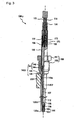
Fig. 1 is a cross-sectional view illustrating a configuration of a temperature sensor that is partially cut away, according to a first embodiment of the invention; -
Fig. 2 is a partially enlarged view ofFig. 1 (upper cross-section), and a lower cross-section showing contraction ofouter tube 120 upon cooling;; -
Fig. 3 is a cross-sectional view illustrating a configuration of a temperature sensor that is partially cut away, according to a second embodiment of the invention; -
Figs. 4(a) and 4(b) are partial cross-sectional views illustrating a fixed state of an outer tube in the temperature sensor according to a second embodiment of the invention; -
Fig. 5 is a partially enlarged view of a cross-section of a temperature sensor according to a third embodiment of the invention; -
Fig. 6 is a partially enlarged view of a cross-section (upper cross-section) of a related art temperature sensor and a lower cross-section showing contraction ofinner tube 512 upon cooling; and -
Fig. 7 is a view illustrating respondences of the temperature sensing part of a temperature sensor, both without and with an outer tube. - Hereinafter, exemplary embodiments of the invention will be described with reference to the drawings. However, the present invention should not be construed as being limited thereto.
-
Fig. 1 illustrates a cross-sectional configuration of a temperature sensor 100x that is partially cut away, according to a first embodiment of the invention. The temperature sensor 100x is inserted through an opening of aside wall 200 of an exhaust pipe to be mounted therein, and detects the temperature of a vehicle exhaust gas. In addition, as the temperature of the exhaust gas changes rapidly between a low temperature of about 0°C and a high temperature of about 1000°C, a thermal cycle of raising/decreasing the temperature within a temperature range is applied to the temperature sensor 100x. - The temperature sensor 100x includes a thermistor (temperature sensing element) 102, a
sheath member 106 connected to thethermistor 102, aninner tube 112 made of a metal (SUS310S is used in this embodiment) which has a bottomed cylindrical shape accommodating thethermistor 102 and thesheath member 106, anouter tube 120 made of a metal (SUS310S is used in this embodiment) which is aligned coaxially with theinner tube 112 and has a cylindrical shape covering theinner tube 112, aflange member 140 fitted to an outer periphery of theinner tube 112, amounting member 150 loosely fitted to an outer periphery of theflange member 140, acylindrical joint 160 made of a metal which is mounted to a rear end side of theflange member 140, and anelastic seal member 174 which is mounted to a rear end of thejoint 160 to pull out alead 173. - In the temperature sensor 100x of this embodiment, a lower end side of the
inner tube 112 is referred to as a "leading end" or "front end", and an open end side of theinner tube 112 is referred to as a "rear side". - The thermistor (temperature sensing element) 102 includes a thermistor sintered body (temperature sensing unit) 103 for measuring temperature and a pair of
device electrode wires 104 extending from an end (rear end side) of the thermistor sinteredbody 103. - The thermistor sintered
body 103 has a hexagonal prism shape provided in theinner tube 112, while an axial direction of the prism is perpendicular to an axial direction of theinner tube 112. As the thermistor sinteredbody 103, a perovskite-structured oxide having (Sr,Y)(Al,Mn,Fe)O3 as a base composition may be used, but is not limited thereto. In addition, as the temperature sensing unit, a resistance thermometer such as Pt in addition to the thermistor may be used. - The
sheath member 106 includes asheath wire 108 connected to each of the pair ofdevice electrode wires 104 of thethermistor 102, and a sheathouter pipe 107 accommodating thesheath wire 108. An insulating material made of SiO2 is filled between thesheath wire 108 and an inner surface of the sheathouter pipe 107. - Typically, the
device electrode wire 504 is a Pt-Rh wire or the like that is expensive. Therefore, by connecting asheath wire 508 made of SUS or the like which is inexpensive, a reduction in cost can be achieved. - The
flange member 140 has a substantially cylindrical shape in which a center hole through which theinner tube 112 is to be inserted opens in an axial direction. From the leading end side of the temperature sensor 100x, aflange portion 142 having a large diameter, a tubular sheathing portion 143 having a smaller diameter than theflange portion 142, a first steppedportion 144 defining a leading end side of the sheathing portion 143, and a second steppedportion 146 which defines a rear end side of the sheathing portion 143 and has a smaller diameter than the first steppedportion 144, are sequentially formed. A leading end surface of theflange portion 142 is provided with a taperedseating surface 145, and when the mountingmember 150 described below is screwed to the exhaust pipe, theseating surface 145 is mounted to theside wall 200 of the exhaust pipe for sealing. - The
flange member 140 is press-fitted to a rear end portion of theinner tube 112, and the entire periphery of the second steppedportion 146 and theinner tube 112 are fixed to each other by laser welding. - In addition, the joint 160 is press-fitted to an outer periphery of the first stepped
portion 144, and the two are fixed to each other by laser-welding the entire periphery. The joint 160 accommodates and retains a connection portion of thesheath wire 108 pulled from thesheath member 106, and thelead 173. - The mounting
member 150 has a center hole with a diameter slightly larger than the outer periphery of the joint 160 in an axial direction and is provided with ascrew portion 152 and ahexagonal nut portion 151 with a diameter larger than that of thescrew portion 152, from a leading end side. In addition, while a rear surface of theflange portion 142 of theflange member 140 comes in contact with a front surface of thescrew portion 152, the mountingmember 150 is loosely fitted to the outer periphery of the flange member 140 (the joint 160) to be rotatable in the axial direction. - In addition, by screwing the
screw portion 152 to a predetermined screw hole of the exhaust pipe, the temperature sensor 100x is mounted to theside wall 200 of the exhaust pipe. - The
outer tube 120 has a cylindrical shape such that both ends open and theouter tube 120 covers theinner tube 112. Theouter tube 120 is crimped at a substantially center position of a portion of theinner tube 112 disposed on a front end side of theflange member 140 to form a crimping portion (fixing portion) 120b and so as to be fixed to theinner tube 112. Afront end 120a of theouter tube 120 is disposed slightly rearward from a front end of theinner tube 112, and a rear end of theouter tube 120 extends to a position substantially contacting theseating surface 145 of theflange portion 142. - In addition, an opening diameter of the
side wall 200 of the exhaust pipe is slightly larger than that of an outside diameter of theouter tube 120 such that theouter tube 120 can be accommodated in the opening of theside wall 200. - From a rear end of the sheath
outer pipe 107 of thesheath member 106, the twosheath wires 108 are pulled, and an end of eachsheath wire 108 is connected to a tighteningterminal 172. The tighteningterminal 172 is connected to thelead 173. In addition, each of thesheath wires 108 and the tighteningterminal 172 is insulated by an insulatingtube 171. - In addition, each lead 173 is pulled out through a lead insertion hole of the
elastic seal member 174 fitted to a rear end inner side of the joint 160 and connected to an external circuit through a connector. - Next, the
outer tube 120 is described with reference toFig. 2 that is a partially enlarged view ofFig. 1 . In addition,Fig. 2 illustrates a cross-section taken in an axial direction of the temperature sensor to include one of the two device electrode wires. - In
Fig. 2 , thethermistor 102 is disposed in an internal space of a bottom portion (leading end side) of theinner tube 112, and thedevice electrode wire 104 extends from arear end 103r of the thermistor sinteredbody 103 along the axial direction L of theinner tube 112. In addition, the sheathouter pipe 107 of thesheath member 106 is accommodated in theinner tube 112 coaxially with theinner tube 112, and thesheath wire 108 pulled from a leading end of the sheathouter pipe 107 of thesheath member 106 overlaps with a leading end of thedevice electrode wire 104. - In addition, an overlapping portion of the
device electrode wire 104 and thesheath wire 108 is formed as ajunction 110 by laser spot welding, and the two are joined at thejunction 110. Thethermistor 102 and thesheath member 106 are connected as described above to be accommodated in theinner tube 112, and the insulatingmaterial 114 fills a space, so that thethermistor 102 and thesheath member 106 are retained in theinner tube 112. The insulatingmaterial 114 may be formed by filling and solidifying an unconsolidated cement having alumina and silica as a main constituent and an aggregate, respectively, in the space. - Here, when viewed in a direction perpendicular to the axial direction L of the
inner tube 112, a front end of thejunction 110 is denoted by J, a position of therear end 103r of the thermistor sinteredbody 103 is denoted by R, a position of afront end 103f of the thermistor sinteredbody 103 is denoted by F, and a position of afront end 112a of theinner tube 112 is denoted by B. In addition, thefront end 112a (position B) of theinner tube 112 corresponds to "the bottom portion of the inner tube" of the claims appended hereto. Also, "the region of the bottom portion of the inner tube" means the region to a rear end side of the position B (including a position the same as (aligned with) the position B) when viewed in the direction perpendicular to the axial direction L. - Here, a position X of the front end (open end) 120a of the
outer tube 120 is at a front end side of the position J and at a rear end side of the position B (in the region of the bottom portion of the inner tube). In addition, theouter tube 120 is spaced from theinner tube 112 at the front end side of the position J. - When the
outer tube 120 is configured as described above, thefront end 112a of theinner tube 112 is exposed from theopen end 120a of theouter tube 120, and thejunction 110 is shielded by theouter tube 120. Accordingly, when the temperature sensor 100x is cooled from a high temperature to a low temperature, cooling starts from theouter tube 120 on an outer periphery side, and theouter tube 120 contracts as illustrated in layerFig. 2 . However, the rapid temperature change is not readily transferred to theinner tube 112 shielded by theouter tube 120. In addition, since theouter tube 120 is spaced from theinner tube 112 at the front end side of thejunction 110, the contraction of theouter tube 120 due to the rapid temperature change is not followed by theinner tube 112, and the degree of the contraction of theinner tube 112 can be reduced. Particularly, since the junction 110 (position J) is shielded by theouter tube 120, stress such as shear stress exerted on thejunction 110 which is caused by the contraction of theinner tube 112 with a change in temperature can be lessened. - In addition, since the
front end 112a of theinner tube 112 is exposed at the open end of theouter tube 120, thefront end 112a is exposed to the exhaust gas, respondence of the thermistor sintered body (temperature sensing unit) 103 housed in thefront end 112a is not deteriorated, and the temperature of the exhaust gas can be measured with good precision. In addition, in this embodiment of the invention, the description that "position X is at a rear end side of the position B" includes the case where position X and position B are flush with each other. This is because thefront end 112a can be exposed to the exhaust gas by the flow of the exhaust gas when the two are flush with each other. - Moreover, since the
junction 110 is shielded by theouter tube 120, the temperature change in the vicinity of thejunction 110 can be smoothened, and thermal stress exerted on thejunction 110 can be reduced, thereby further enhancing reliability of the temperature sensor. - In addition, in this embodiment, the
outer tube 120 is exemplified as having an outside diameter of 4.45 mm and a thickness of 0.3 mm, and theinner tube 112 is exemplified as having an outside diameter of 2.65 mm. In this case, a distance from theouter tube 120 to theinner tube 112 is 0.6 mm. - Further, in this embodiment, in a portion where the
inner tube 112 and theouter tube 120 are separated on a front side from thejunction 110, when a maximum outer diameter of the inner tube is defined as φ1 and a minimum inner diameter of the outer tube is defined as φ2, the relationship φ1<φ2≤2×φ1 1 is satisfied. - By having such a configuration, the
inner tube 112 and theouter tube 120 can be securely separated on a front side from thejunction 110, and thejunction 110 is effectively shielded by theouter tube 120. On the one hand, since theouter tube 120 is not much larger than the inner tube 112 (an inner diameter of theouter tube 120 is not more than two times an outer diameter of theinner tube 112 at the most), the possibility of lowering the shielding effect is reduced. Further, a crimping defect or the like upon attaching the outer tube by crimping or the like is not likely to occur, thereby improving productivity or assembly accuracy. - Further, in a cross-section of
Fig. 2 , a gap G1 is formed between an upper surface of theinner tube 112 and theouter tube 120, and a gap G2 is formed between a lower surface of theinner tube 112 and theouter tube 120. In this case, the relationship φ2-φ1 = G1+G2 is satisfied. - In a case where a cross-section of the outer tube is not circular (for example, in the case of an elliptical shape), two times a shortest distance among distances from a center of the outer tube to an inner surface of the outer tube in an outward radial direction is defined as φ2. Similarly, in the case where the cross-section of the inner tube is not circular (for example, in the case of an elliptical shape), two times a longest distance among distances from a center of the inner tube to an outer surface of the inner tube in an outward radial direction is defined as φ1.
- Furthermore, φ1 and φ2 target a portion reaching a front end of the
outer tube 120 at a front end side of thejunction 110. For example, in the case where theouter tube 120 is tapered toward the front end, an inner diameter of theouter tube 120 at the front end is taken as φ2. - In addition, in this embodiment, the
outer tube 120 is fixed to theinner tube 112 by the crimpingportion 120b at a rear end side of the position J. When a fixing position of theinner tube 112 and theouter tube 120 is at a rear end side of the position J, the contraction of theinner tube 112 following the contraction of theouter tube 120 due to the rapid temperature change can be effectively prevented. Particularly, the fixing position of theinner tube 112 and theouter tube 120 is more preferably at a rear end side of the position S. - In addition, the rear end of the
outer tube 120 preferably extends at least to a rear end (position S) of the sheath wire 108 (where thesheath wire 108 is taken out of the front end of the sheath outer pipe 107) extending from the junction. - In addition, when the position X is at a front end side of the position R, the
outer tube 120 covers thedevice electrode wire 104 close to thejunction 110 on which shear stress is exerted due to contraction with a change in temperature. Consequently, the stress exerted on thejunction 110 can be further lessened. - In addition, when the position X is at a rear end side of the position F, the
inner tube 112 in the vicinity of the thermistor sintered body (temperature sensing unit) 103 is always exposed to the exhaust gas. Therefore, the respondence of the thermistor sintered body (temperature sensing unit) 103 is further enhanced, and precision of the temperature measurement of the exhaust gas can be further increased. - In addition, in this embodiment, the insulating
material 114 fills the space between the thermistor sintered body (temperature sensing unit) 103 and theinner tube 112, and the thermistor sinteredbody 103 and theinner tube 112 are formed integrally with each other. Accordingly, the extent of pressing the thermistor sinteredbody 103 to the rear side (sheath member side) when theinner tube 112 contracts with a change in temperature is increased, so as to exhibit the significant effects of this embodiment of the invention. In addition, when the insulating member fills the space between the thermistor sinteredbody 103 and theinner tube 112, heat is rapidly transferred from theinner tube 112 to the thermistor sinteredbody 103, thereby further enhancing the respondence of the thermistor sinteredbody 103. - Various configurations for retaining the thermistor sintered
body 103 in theinner tube 112 include, in addition to the above-mentioned filling of the insulating material, a retaining configuration for retaining the thermistor sinteredbody 103 by disposing a holder in the vicinity of the thermistor sinteredbody 103 and filling the holder with an insulating material, a retaining configuration of allowing the thermistor sinteredbody 103 to come in contact with (be adhered to, or the like) a leading end inner wall or a side wall of theinner tube 112, or the like. In this embodiment of the invention, the above-mentioned retaining configuration is employed. - Next, a temperature sensor 100y according to a second embodiment of the invention will be described with reference to
Fig. 3. Fig. 3 illustrates a cross-sectional configuration of the temperature sensor 100y that is partially cut away. The temperature sensor 100y is the same as that of the first embodiment, except that configurations of aflange member 140y and anouter tube 120y are different from those of the first embodiment. Like elements in the first embodiment are denoted by like reference numerals, and a detailed description thereof will be omitted. - The temperature sensor 100y is different from that of the first embodiment in that the
outer tube 120y is not fixed by crimping to theinner tube 112, but rather by means of theflange member 140y. Specifically, acylindrical guide portion 145a extends from theseating surface 145 formed on the front end surface of theflange portion 142 of theflange member 140y toward the front end side. Theguide portion 145a has a center hole provided coaxially with theflange member 140y, and an outside diameter of theguide portion 145a is slightly larger than an inside diameter of theouter tube 120y. - In addition, as illustrated in
Fig. 4 , when theouter tube 120y is insert-fitted to theguide portion 145a and welded thereto, theouter tube 120y is fixed to theguide portion 145a with a welding portion w (Fig. 4(a) ). The temperature sensor 100y configured as described above is mounted to the side wall 200 (of the exhaust pipe). - In addition, as a method of fixing the outer tube without welding, as illustrated in
Fig. 4(b) , aflange portion 120z is provided by increasing a diameter of a rear end of theouter tube 120y such that the rear end is along theseating surface 145. In this case, when the temperature sensor 100y is inserted into the side wall 200 (of the exhaust pipe) after insert-fitting theouter tube 120y to theguide portion 145a, theflange portion 120z is fitted and retained between theseating surface 145 and theside wall 200. - In addition, in the second embodiment illustrated in
Fig. 4(a) , theguide portion 145a serves as the fixing portion of the outer tube. In the second embodiment illustrated inFig. 4(b) , theseating surface 145 serves as the fixing portion of the outer tube, and when the temperature sensor 100y is mounted to an object, theseating surface 145 functions as the fixing portion. - Next, a temperature sensor 100z according to a third embodiment of the invention will be described with reference to
Fig. 5. Fig. 5 is a partially enlarged view corresponding toFig. 2 , and illustrates a cross-section taken in a direction parallel with an axial direction of the temperature sensor 100z to include one of the twodevice electrode wires 104. The temperature sensor 100z is the same as that of the first embodiment, except that a configuration of theinner tube 1120 is different. Like elements in the first embodiment are denoted by like reference numerals, and a detailed description thereof will be omitted. In addition, a configuration of parts not shown inFig. 5 is the same as that inFig. 1 . - In the temperature sensor 100z, the
inner tube 1120 covers a region from thethermistor 102 to the position S, and the entire periphery thereof is laser-welded to the leading end of the sheathouter pipe 107 in the vicinity of the position S. In this manner, theinner tube 1120 is not present on a rear end side from the welding position so as to expose the sheathouter pipe 107. In addition, theouter tube 120 is crimped (crimpedportion 120b) and fixed to the sheathouter pipe 107. Moreover, a rear end side of thesheath member 106 is inserted through the center hole of theflange member 140 and retained by theflange member 140. - The invention is not limited to the above embodiments, and various changes in form and detail of the invention as shown and described above can be made without departing from the spirit and scope of the claims appended hereto. For example, the material of the outer tube is not particularly limited, and various types of heat-resistant materials such as ceramics may be used in addition to the metal.
- A temperature sensor having a structure shown in
Fig. 1 , was manufactured, including aninner tube 112 having an outer diameter of 2.65mm, and anouter tube 120 having a diameter which differed so that a gap (value of (G1+G2)/2 ofFig. 2 ) between theouter tube 120 and theinner tube 112 assumed the values shown in Table 1. - This temperature sensor was mounted in a predetermined chamber and air heated at 800°C was blown into the chamber from an external burner for 5 minutes. Then, the burner was deactivated and room temperature air was blown into the chamber for 1 minute to carry out cooling. This heating and cooling were taken as 1 cycle, and the temperature sensor in the chamber was subjected to thermal cycling for the number of cycles shown in Table 1 to establish a thermal history. During the thermal cycling, the chamber was vibrated while sweeping at a frequency ranging from 150 Hz to 3000Hz.
- After completing the test, the temperature sensor was disassembled, and visually evaluated to determine whether breakage occurred at a welded portion of the
junction 110. The results thus obtained are shown in Table 1.Table 1 Outer tube Gap between outer tube and inner tube (mm) Maximum outer diameter of inner tube φ1(mm) Minimum inner diameter of outer tube φ2(mm) φ2/φ1 Number of Thermal Cycles State of junction Absent - 2.65 - - 1300 X - 2.65 - - 2000 X - 2.65 - - 1600 X Present 0.6 2.65 3.85 1.45 4000 O 0.6 2.65 3.85 1.45 3500 O 1.3 2.65 5.25 1.98 3500 O - As is apparent from Table 1, it was found that, in the case where an outer tube was provided, the welded portion of the junction was not broken (O) even though the temperature sensor was subjected to thermal cycling applied under vibration, and stress to the junction was relieved.
- On the other hand, it was found that, in the case where an outer tube was not provided, the welded portion of the junction was broken (X) when the temperature sensor was subjected to thermal cycling under vibration, and stress to the junction could not be relieved.
- Next, the various temperature sensors (sensors without an outer tube, and sensors of φ2/φ1 = 1.45 or 1.98) shown in Table 1 were mounted to a pipe located downstream of an electric furnace (ambient atmosphere) of 600°C, and the temperature was measured at a flow rate of 20m/s in the pipe. Here, temperature sensors prior to being subjected to thermal cycling were employed.
- Values of temperature measurement by the respective temperature sensors with elapsed time from when warm air first flowed in the pipe from the electric furnace are shown in
Fig. 7 . The curves inFig. 7 represent responsiveness of a temperature sensing part built in the front end of the temperature sensor, and the responsiveness is evaluated as good if the measurement value reaches 500°C or higher after 25 seconds from the start of measurement. The present inventors confirmed that the responsiveness was good in the range of φ2/φ1 = 1.45 to 1.98, similar to the case where an outer tube was not provided (that is, the case where responsiveness is highest). - This application is based on Japanese Patent Application No.
2008-123024, filed May 9, 2008 2009-104434 filed April 22, 2009 - In summary, a temperature sensor is disclosed, including: a temperature sensing element having a temperature sensing unit and a pair of device electrode wires, a sheath member having a sheath wire connected at a junction to at least one of the device electrode wires and a sheath outer pipe retaining the sheath wire in an insulating material; an inner tube which has a bottomed cylindrical shape; and a cylindrical outer tube having an open end, covering the inner tube such that the open end is located at a front end side of the junction and in a region to the rear end side of or aligned with the front end of the inner tube, and being spaced from the inner tube at the front end side of the junction.
Claims (15)
- A temperature sensor comprising:a temperature sensing element having a temperature sensing unit and a pair of device electrode wires extending from the temperature sensing unit;a sheath member including a sheath wire connected at a junction to at least one of the device electrode wires and a sheath outer pipe retaining the sheath wire in an insulating material;an inner tube made of a metal which has a bottomed cylindrical shape, said inner tube accommodating the temperature sensing element and the junction in a bottom portion side of the inner tube serving as a front end of the temperature sensor, and extending in an extension direction of the device electrode wire and the sheath wire; anda cylindrical outer tube having an open end, when viewed in a direction perpendicular to an axial direction of the inner tube, said outer tube covering the inner tube such that the open end is located at a front end side of the junction and in a region to the rear end side of or aligned with the front end of the inner tube, and being spaced from the inner tube at the front end side of the junction.
- The temperature sensor according to claim 1, further comprising:a fixing portion for fixing the outer tube to the inner tube or the sheath outer pipe at a rear end side of the junction when viewed in a direction perpendicular to the axial direction of the inner tube.
- The temperature sensor according to claim 1 or 2,
wherein the open end is located at the front end side of a rear end of the temperature sensing unit when viewed in a direction perpendicular to the axial direction of the inner tube. - The temperature sensor according to any one of claims 1 to 3,
wherein the open end is located at the rear end side of a front end of the temperature sensing unit when viewed from a direction perpendicular to the axial direction of the inner tube. - The temperature sensor according to any one of claims 1 to 4,
wherein the insulating material is filled between the temperature sensing element and an inner surface of the inner tube. - The temperature sensor according to any one of claims 1 to 5,
wherein in a portion where the inner tube and the outer tube are separated at a front side of the junction, when a maximum outer diameter of the inner tube is defined as φ1 and a minimum inner diameter of the outer tube is defined as φ2, the relationship φ1<φ2≤2×φ1 is satisfied. - A method of manufacturing a temperature sensor, comprising:- connecting a sheath member (106) to a temperature sensing element (102);- accommodating the sheath member (106) and the temperature sensing element (102) in an inner tube (112);- coaxially aligning an outer tube (120) with the inner tube (112);- fitting a flange member (140) to an outer periphery of the inner tube (112);- fitting a mounting member (150) loosely to an outer periphery of the flange member (140);- mounting a joint (160) to a rear end side of the flange member (140); and- mounting an elastic seal member (174) to a rear end of the joint (160) tu pull out a lead (173).
- The method according to claim 7, wherein the flange member (140) is press-fitted to a rear end portion of the inner tube (112).
- The method according to claim 7 or 8, wherein an entire periphery of a stepped portion (146) of the flange member (140) is fixed to the inner tube (112).
- The method according to claim 9, wherein the fixing is made by welding, in particular laser welding.
- The method according to one of claims 7 to 10, wherein the joint (160) is press-fitted to an outer periphery of a stepped portion (144) of the flange member (140).
- The method according to claim 11, wherein the joint (160) is welded, in particular laser welded to the stepped portion at the entire periphery.
- The method according to one of claims 7 to 12, further comprising attaching the temperature sensor so manufactured, or the temperature sensor according to one of claims 1 to 5, to an exhaust pipe, in particular on a sidewall thereof.
- The method according to one of claims 7 to 13, further comprising using the temperature sensor so manufactured for detecting the temperature of exhaust gas of a vehicle.
- Use of the temperature sensor of one of claims 1 to 6, for detecting the temperature of exhaust gas of a vehicle.
Applications Claiming Priority (2)
| Application Number | Priority Date | Filing Date | Title |
|---|---|---|---|
| JP2008123024 | 2008-05-09 | ||
| JP2009104434A JP5155246B2 (en) | 2008-05-09 | 2009-04-22 | Temperature sensor |
Publications (2)
| Publication Number | Publication Date |
|---|---|
| EP2116831A1 true EP2116831A1 (en) | 2009-11-11 |
| EP2116831B1 EP2116831B1 (en) | 2015-09-16 |
Family
ID=40957844
Family Applications (1)
| Application Number | Title | Priority Date | Filing Date |
|---|---|---|---|
| EP09006344.7A Active EP2116831B1 (en) | 2008-05-09 | 2009-05-11 | Temperature sensor |
Country Status (5)
| Country | Link |
|---|---|
| US (1) | US8192081B2 (en) |
| EP (1) | EP2116831B1 (en) |
| JP (1) | JP5155246B2 (en) |
| KR (1) | KR101630452B1 (en) |
| CN (1) | CN101576420B (en) |
Families Citing this family (11)
| Publication number | Priority date | Publication date | Assignee | Title |
|---|---|---|---|---|
| JP5198934B2 (en) * | 2008-05-09 | 2013-05-15 | 日本特殊陶業株式会社 | Temperature sensor |
| IT1393070B1 (en) * | 2008-10-24 | 2012-04-11 | Worgas Bruciatori Srl | SPECIAL THERMOCOUPLE FOR BURNERS |
| JP4541436B2 (en) * | 2008-11-27 | 2010-09-08 | 日本特殊陶業株式会社 | Temperature sensor |
| JP5134701B2 (en) * | 2010-07-20 | 2013-01-30 | 日本特殊陶業株式会社 | Temperature sensor |
| DE102010031917B3 (en) * | 2010-07-22 | 2012-02-02 | Borgwarner Beru Systems Gmbh | temperature sensor |
| JP5784989B2 (en) * | 2011-05-31 | 2015-09-24 | 株式会社クボタ | Engine exhaust heat temperature detector |
| DE102013009033A1 (en) * | 2012-07-18 | 2014-01-23 | Tesona Gmbh & Co. Kg | High-temperature measurement sensor arrangement |
| WO2014041168A2 (en) * | 2012-09-17 | 2014-03-20 | Tesona Gmbh & Co.Kg | High temperature sensor with a protective tube in the cold section |
| US10428716B2 (en) * | 2016-12-20 | 2019-10-01 | Sensata Technologies, Inc. | High-temperature exhaust sensor |
| CN107219009A (en) * | 2017-08-02 | 2017-09-29 | 武汉优斯特汽车传感器科技有限公司 | A kind of temperature sensor |
| DE102019117865A1 (en) * | 2018-07-13 | 2020-01-16 | Ngk Spark Plug Co., Ltd. | TEMPERATURE SENSOR |
Citations (5)
| Publication number | Priority date | Publication date | Assignee | Title |
|---|---|---|---|---|
| US4485263A (en) * | 1981-09-29 | 1984-11-27 | Tokyo Shibaura Denki Kabushiki Kaisha | Thermocouple instrument |
| JPH05264368A (en) | 1992-03-17 | 1993-10-12 | Ngk Spark Plug Co Ltd | Sensor assembling structure |
| US5917145A (en) * | 1996-03-14 | 1999-06-29 | Alcan International Limited | Method and apparatus for measurement of temperatures of molten aluminum and aluminum alloys |
| JP2000097781A (en) | 1998-07-24 | 2000-04-07 | Denso Corp | Temperature sensor and manufacture thereof |
| DE102004033958A1 (en) * | 2004-07-14 | 2006-02-09 | Robert Bosch Gmbh | probe |
Family Cites Families (18)
| Publication number | Priority date | Publication date | Assignee | Title |
|---|---|---|---|---|
| US4018624A (en) * | 1973-08-22 | 1977-04-19 | Engelhard Minerals & Chemicals Corporation | Thermocouple structure and method of manufacturing same |
| US4453835A (en) * | 1982-05-03 | 1984-06-12 | Clawson Burrell E | Temperature sensor |
| JPS59117930U (en) * | 1983-01-31 | 1984-08-09 | 株式会社芝浦電子製作所 | temperature sensor |
| US4467134A (en) * | 1983-06-30 | 1984-08-21 | General Electric Company | Thermocouple with out-of-line aspiration holes |
| JP2596789B2 (en) * | 1988-05-16 | 1997-04-02 | 新日本製鐵株式会社 | Protection tube type thermometer |
| DE4431291B4 (en) * | 1994-09-02 | 2004-03-25 | Alstom | High temperature probe |
| JP3588897B2 (en) * | 1996-02-09 | 2004-11-17 | 株式会社デンソー | Stack type temperature sensor |
| JPH11218449A (en) | 1997-11-21 | 1999-08-10 | Denso Corp | Temp. sensor and manufacture thereof |
| WO2001027579A1 (en) * | 1999-10-13 | 2001-04-19 | Texaco Development Corporation | Sapphire reinforced thermocouple protection tube |
| JP2002267547A (en) * | 2001-03-14 | 2002-09-18 | Denso Corp | Temperature sensor |
| US6762671B2 (en) * | 2002-10-25 | 2004-07-13 | Delphi Technologies, Inc. | Temperature sensor and method of making and using the same |
| US6997607B2 (en) * | 2002-11-22 | 2006-02-14 | Ngk Spark Plug Co., Ltd. | Temperature sensor |
| US7060949B1 (en) * | 2003-05-16 | 2006-06-13 | Watlow Electric Manufacturing Company | End seal design for temperature sensing probes |
| US7740403B2 (en) * | 2004-02-09 | 2010-06-22 | Temperaturmesstechnik Geraberg Gmbh | High-temperature sensor |
| JP4620400B2 (en) * | 2004-07-16 | 2011-01-26 | 日本特殊陶業株式会社 | Temperature sensor and method of manufacturing temperature sensor |
| JP4768432B2 (en) * | 2005-12-21 | 2011-09-07 | 日本特殊陶業株式会社 | Temperature sensor manufacturing method and temperature sensor |
| US7458718B2 (en) * | 2006-02-22 | 2008-12-02 | Honeywell International Inc. | Temperature sensor that achieves a fast response in an exhaust gas environment |
| US7841769B2 (en) * | 2007-09-11 | 2010-11-30 | Gm Global Technology Operations, Inc. | Method and apparatus for determining temperature in a gas feedstream |
-
2009
- 2009-04-22 JP JP2009104434A patent/JP5155246B2/en active Active
- 2009-05-08 KR KR1020090040235A patent/KR101630452B1/en active IP Right Grant
- 2009-05-08 US US12/437,614 patent/US8192081B2/en active Active
- 2009-05-11 EP EP09006344.7A patent/EP2116831B1/en active Active
- 2009-05-11 CN CN200910137554.5A patent/CN101576420B/en active Active
Patent Citations (5)
| Publication number | Priority date | Publication date | Assignee | Title |
|---|---|---|---|---|
| US4485263A (en) * | 1981-09-29 | 1984-11-27 | Tokyo Shibaura Denki Kabushiki Kaisha | Thermocouple instrument |
| JPH05264368A (en) | 1992-03-17 | 1993-10-12 | Ngk Spark Plug Co Ltd | Sensor assembling structure |
| US5917145A (en) * | 1996-03-14 | 1999-06-29 | Alcan International Limited | Method and apparatus for measurement of temperatures of molten aluminum and aluminum alloys |
| JP2000097781A (en) | 1998-07-24 | 2000-04-07 | Denso Corp | Temperature sensor and manufacture thereof |
| DE102004033958A1 (en) * | 2004-07-14 | 2006-02-09 | Robert Bosch Gmbh | probe |
Also Published As
| Publication number | Publication date |
|---|---|
| US20090279585A1 (en) | 2009-11-12 |
| CN101576420A (en) | 2009-11-11 |
| US8192081B2 (en) | 2012-06-05 |
| JP5155246B2 (en) | 2013-03-06 |
| JP2009294203A (en) | 2009-12-17 |
| KR20090117658A (en) | 2009-11-12 |
| CN101576420B (en) | 2014-07-09 |
| KR101630452B1 (en) | 2016-06-14 |
| EP2116831B1 (en) | 2015-09-16 |
Similar Documents
| Publication | Publication Date | Title |
|---|---|---|
| EP2116831B1 (en) | Temperature sensor | |
| EP2116830B1 (en) | Temperature sensor | |
| EP2141471B1 (en) | Temperature sensor | |
| US7581879B2 (en) | Temperature sensor | |
| US6639505B2 (en) | Temperature sensor | |
| US6899457B2 (en) | Thermistor temperature sensor | |
| US7104685B2 (en) | Temperature sensor with quick response | |
| US8092086B2 (en) | Temperature sensor | |
| US6997607B2 (en) | Temperature sensor | |
| JP6608088B1 (en) | Temperature sensor | |
| EP3339825B1 (en) | High-temperature exhaust sensor | |
| US10302507B2 (en) | Temperature sensor and method for manufacturing the same | |
| JP2002107233A (en) | Thermocouple device | |
| JP2009300237A (en) | Temperature sensor and method of manufacturing the same | |
| JP3826095B2 (en) | Temperature sensor | |
| JP5519590B2 (en) | Temperature sensor manufacturing method and temperature sensor | |
| JP4059222B2 (en) | Temperature sensor and method of manufacturing temperature sensor | |
| JP5123344B2 (en) | Temperature sensor | |
| JP5651550B2 (en) | Temperature sensor and method of manufacturing temperature sensor | |
| CN110715751B (en) | Temperature sensor | |
| JP6406786B2 (en) | Gas sensor | |
| JP2004286490A (en) | Temperature sensor | |
| JP6576766B2 (en) | Temperature sensor | |
| JP2005106685A (en) | Gas sensor | |
| JP2020016633A (en) | Temperature sensor |
Legal Events
| Date | Code | Title | Description |
|---|---|---|---|
| PUAI | Public reference made under article 153(3) epc to a published international application that has entered the european phase |
Free format text: ORIGINAL CODE: 0009012 |
|
| AK | Designated contracting states |
Kind code of ref document: A1 Designated state(s): AT BE BG CH CY CZ DE DK EE ES FI FR GB GR HR HU IE IS IT LI LT LU LV MC MK MT NL NO PL PT RO SE SI SK TR |
|
| 17P | Request for examination filed |
Effective date: 20091221 |
|
| 17Q | First examination report despatched |
Effective date: 20100128 |
|
| 17Q | First examination report despatched |
Effective date: 20101013 |
|
| GRAP | Despatch of communication of intention to grant a patent |
Free format text: ORIGINAL CODE: EPIDOSNIGR1 |
|
| INTG | Intention to grant announced |
Effective date: 20150331 |
|
| GRAS | Grant fee paid |
Free format text: ORIGINAL CODE: EPIDOSNIGR3 |
|
| GRAA | (expected) grant |
Free format text: ORIGINAL CODE: 0009210 |
|
| AK | Designated contracting states |
Kind code of ref document: B1 Designated state(s): AT BE BG CH CY CZ DE DK EE ES FI FR GB GR HR HU IE IS IT LI LT LU LV MC MK MT NL NO PL PT RO SE SI SK TR |
|
| REG | Reference to a national code |
Ref country code: GB Ref legal event code: FG4D |
|
| REG | Reference to a national code |
Ref country code: CH Ref legal event code: EP |
|
| REG | Reference to a national code |
Ref country code: IE Ref legal event code: FG4D |
|
| REG | Reference to a national code |
Ref country code: AT Ref legal event code: REF Ref document number: 750164 Country of ref document: AT Kind code of ref document: T Effective date: 20151015 |
|
| REG | Reference to a national code |
Ref country code: DE Ref legal event code: R096 Ref document number: 602009033620 Country of ref document: DE |
|
| REG | Reference to a national code |
Ref country code: NL Ref legal event code: MP Effective date: 20150916 |
|
| PG25 | Lapsed in a contracting state [announced via postgrant information from national office to epo] |
Ref country code: GR Free format text: LAPSE BECAUSE OF FAILURE TO SUBMIT A TRANSLATION OF THE DESCRIPTION OR TO PAY THE FEE WITHIN THE PRESCRIBED TIME-LIMIT Effective date: 20151217 Ref country code: NO Free format text: LAPSE BECAUSE OF FAILURE TO SUBMIT A TRANSLATION OF THE DESCRIPTION OR TO PAY THE FEE WITHIN THE PRESCRIBED TIME-LIMIT Effective date: 20151216 Ref country code: LV Free format text: LAPSE BECAUSE OF FAILURE TO SUBMIT A TRANSLATION OF THE DESCRIPTION OR TO PAY THE FEE WITHIN THE PRESCRIBED TIME-LIMIT Effective date: 20150916 Ref country code: FI Free format text: LAPSE BECAUSE OF FAILURE TO SUBMIT A TRANSLATION OF THE DESCRIPTION OR TO PAY THE FEE WITHIN THE PRESCRIBED TIME-LIMIT Effective date: 20150916 Ref country code: LT Free format text: LAPSE BECAUSE OF FAILURE TO SUBMIT A TRANSLATION OF THE DESCRIPTION OR TO PAY THE FEE WITHIN THE PRESCRIBED TIME-LIMIT Effective date: 20150916 |
|
| REG | Reference to a national code |
Ref country code: LT Ref legal event code: MG4D |
|
| REG | Reference to a national code |
Ref country code: AT Ref legal event code: MK05 Ref document number: 750164 Country of ref document: AT Kind code of ref document: T Effective date: 20150916 |
|
| PG25 | Lapsed in a contracting state [announced via postgrant information from national office to epo] |
Ref country code: SE Free format text: LAPSE BECAUSE OF FAILURE TO SUBMIT A TRANSLATION OF THE DESCRIPTION OR TO PAY THE FEE WITHIN THE PRESCRIBED TIME-LIMIT Effective date: 20150916 Ref country code: HR Free format text: LAPSE BECAUSE OF FAILURE TO SUBMIT A TRANSLATION OF THE DESCRIPTION OR TO PAY THE FEE WITHIN THE PRESCRIBED TIME-LIMIT Effective date: 20150916 |
|
| PG25 | Lapsed in a contracting state [announced via postgrant information from national office to epo] |
Ref country code: NL Free format text: LAPSE BECAUSE OF FAILURE TO SUBMIT A TRANSLATION OF THE DESCRIPTION OR TO PAY THE FEE WITHIN THE PRESCRIBED TIME-LIMIT Effective date: 20150916 |
|
| REG | Reference to a national code |
Ref country code: FR Ref legal event code: PLFP Year of fee payment: 8 |
|
| PG25 | Lapsed in a contracting state [announced via postgrant information from national office to epo] |
Ref country code: IT Free format text: LAPSE BECAUSE OF FAILURE TO SUBMIT A TRANSLATION OF THE DESCRIPTION OR TO PAY THE FEE WITHIN THE PRESCRIBED TIME-LIMIT Effective date: 20150916 Ref country code: ES Free format text: LAPSE BECAUSE OF FAILURE TO SUBMIT A TRANSLATION OF THE DESCRIPTION OR TO PAY THE FEE WITHIN THE PRESCRIBED TIME-LIMIT Effective date: 20150916 Ref country code: SK Free format text: LAPSE BECAUSE OF FAILURE TO SUBMIT A TRANSLATION OF THE DESCRIPTION OR TO PAY THE FEE WITHIN THE PRESCRIBED TIME-LIMIT Effective date: 20150916 Ref country code: EE Free format text: LAPSE BECAUSE OF FAILURE TO SUBMIT A TRANSLATION OF THE DESCRIPTION OR TO PAY THE FEE WITHIN THE PRESCRIBED TIME-LIMIT Effective date: 20150916 Ref country code: CZ Free format text: LAPSE BECAUSE OF FAILURE TO SUBMIT A TRANSLATION OF THE DESCRIPTION OR TO PAY THE FEE WITHIN THE PRESCRIBED TIME-LIMIT Effective date: 20150916 Ref country code: IS Free format text: LAPSE BECAUSE OF FAILURE TO SUBMIT A TRANSLATION OF THE DESCRIPTION OR TO PAY THE FEE WITHIN THE PRESCRIBED TIME-LIMIT Effective date: 20160116 |
|
| PG25 | Lapsed in a contracting state [announced via postgrant information from national office to epo] |
Ref country code: RO Free format text: LAPSE BECAUSE OF FAILURE TO SUBMIT A TRANSLATION OF THE DESCRIPTION OR TO PAY THE FEE WITHIN THE PRESCRIBED TIME-LIMIT Effective date: 20150916 Ref country code: PT Free format text: LAPSE BECAUSE OF FAILURE TO SUBMIT A TRANSLATION OF THE DESCRIPTION OR TO PAY THE FEE WITHIN THE PRESCRIBED TIME-LIMIT Effective date: 20160118 Ref country code: PL Free format text: LAPSE BECAUSE OF FAILURE TO SUBMIT A TRANSLATION OF THE DESCRIPTION OR TO PAY THE FEE WITHIN THE PRESCRIBED TIME-LIMIT Effective date: 20150916 Ref country code: AT Free format text: LAPSE BECAUSE OF FAILURE TO SUBMIT A TRANSLATION OF THE DESCRIPTION OR TO PAY THE FEE WITHIN THE PRESCRIBED TIME-LIMIT Effective date: 20150916 |
|
| REG | Reference to a national code |
Ref country code: DE Ref legal event code: R097 Ref document number: 602009033620 Country of ref document: DE |
|
| PLBE | No opposition filed within time limit |
Free format text: ORIGINAL CODE: 0009261 |
|
| STAA | Information on the status of an ep patent application or granted ep patent |
Free format text: STATUS: NO OPPOSITION FILED WITHIN TIME LIMIT |
|
| 26N | No opposition filed |
Effective date: 20160617 |
|
| PG25 | Lapsed in a contracting state [announced via postgrant information from national office to epo] |
Ref country code: BE Free format text: LAPSE BECAUSE OF NON-PAYMENT OF DUE FEES Effective date: 20160531 Ref country code: DK Free format text: LAPSE BECAUSE OF FAILURE TO SUBMIT A TRANSLATION OF THE DESCRIPTION OR TO PAY THE FEE WITHIN THE PRESCRIBED TIME-LIMIT Effective date: 20150916 |
|
| PG25 | Lapsed in a contracting state [announced via postgrant information from national office to epo] |
Ref country code: SI Free format text: LAPSE BECAUSE OF FAILURE TO SUBMIT A TRANSLATION OF THE DESCRIPTION OR TO PAY THE FEE WITHIN THE PRESCRIBED TIME-LIMIT Effective date: 20150916 |
|
| PG25 | Lapsed in a contracting state [announced via postgrant information from national office to epo] |
Ref country code: BE Free format text: LAPSE BECAUSE OF FAILURE TO SUBMIT A TRANSLATION OF THE DESCRIPTION OR TO PAY THE FEE WITHIN THE PRESCRIBED TIME-LIMIT Effective date: 20150916 Ref country code: LU Free format text: LAPSE BECAUSE OF FAILURE TO SUBMIT A TRANSLATION OF THE DESCRIPTION OR TO PAY THE FEE WITHIN THE PRESCRIBED TIME-LIMIT Effective date: 20160511 |
|
| REG | Reference to a national code |
Ref country code: CH Ref legal event code: PL |
|
| GBPC | Gb: european patent ceased through non-payment of renewal fee |
Effective date: 20160511 |
|
| PG25 | Lapsed in a contracting state [announced via postgrant information from national office to epo] |
Ref country code: CH Free format text: LAPSE BECAUSE OF NON-PAYMENT OF DUE FEES Effective date: 20160531 Ref country code: LI Free format text: LAPSE BECAUSE OF NON-PAYMENT OF DUE FEES Effective date: 20160531 |
|
| REG | Reference to a national code |
Ref country code: IE Ref legal event code: MM4A |
|
| REG | Reference to a national code |
Ref country code: FR Ref legal event code: PLFP Year of fee payment: 9 |
|
| PG25 | Lapsed in a contracting state [announced via postgrant information from national office to epo] |
Ref country code: GB Free format text: LAPSE BECAUSE OF NON-PAYMENT OF DUE FEES Effective date: 20160511 Ref country code: IE Free format text: LAPSE BECAUSE OF NON-PAYMENT OF DUE FEES Effective date: 20160511 |
|
| REG | Reference to a national code |
Ref country code: FR Ref legal event code: PLFP Year of fee payment: 10 |
|
| PG25 | Lapsed in a contracting state [announced via postgrant information from national office to epo] |
Ref country code: CY Free format text: LAPSE BECAUSE OF FAILURE TO SUBMIT A TRANSLATION OF THE DESCRIPTION OR TO PAY THE FEE WITHIN THE PRESCRIBED TIME-LIMIT Effective date: 20150916 Ref country code: HU Free format text: LAPSE BECAUSE OF FAILURE TO SUBMIT A TRANSLATION OF THE DESCRIPTION OR TO PAY THE FEE WITHIN THE PRESCRIBED TIME-LIMIT; INVALID AB INITIO Effective date: 20090511 |
|
| PG25 | Lapsed in a contracting state [announced via postgrant information from national office to epo] |
Ref country code: TR Free format text: LAPSE BECAUSE OF FAILURE TO SUBMIT A TRANSLATION OF THE DESCRIPTION OR TO PAY THE FEE WITHIN THE PRESCRIBED TIME-LIMIT Effective date: 20150916 Ref country code: MK Free format text: LAPSE BECAUSE OF FAILURE TO SUBMIT A TRANSLATION OF THE DESCRIPTION OR TO PAY THE FEE WITHIN THE PRESCRIBED TIME-LIMIT Effective date: 20150916 Ref country code: MC Free format text: LAPSE BECAUSE OF FAILURE TO SUBMIT A TRANSLATION OF THE DESCRIPTION OR TO PAY THE FEE WITHIN THE PRESCRIBED TIME-LIMIT Effective date: 20150916 Ref country code: MT Free format text: LAPSE BECAUSE OF NON-PAYMENT OF DUE FEES Effective date: 20160531 |
|
| PG25 | Lapsed in a contracting state [announced via postgrant information from national office to epo] |
Ref country code: BG Free format text: LAPSE BECAUSE OF FAILURE TO SUBMIT A TRANSLATION OF THE DESCRIPTION OR TO PAY THE FEE WITHIN THE PRESCRIBED TIME-LIMIT Effective date: 20150916 |
|
| PGFP | Annual fee paid to national office [announced via postgrant information from national office to epo] |
Ref country code: FR Payment date: 20210412 Year of fee payment: 13 |
|
| PG25 | Lapsed in a contracting state [announced via postgrant information from national office to epo] |
Ref country code: FR Free format text: LAPSE BECAUSE OF NON-PAYMENT OF DUE FEES Effective date: 20220531 |
|
| PGFP | Annual fee paid to national office [announced via postgrant information from national office to epo] |
Ref country code: DE Payment date: 20230331 Year of fee payment: 15 |
|
| REG | Reference to a national code |
Ref country code: DE Ref legal event code: R081 Ref document number: 602009033620 Country of ref document: DE Owner name: NITERRA CO., LTD., NAGOYA-SHI, JP Free format text: FORMER OWNER: NGK SPARK PLUG CO., LTD., NAGOYA-SHI, AICHI-KEN, JP |