EP2116404A1 - Glass run channel assembly - Google Patents
Glass run channel assembly Download PDFInfo
- Publication number
- EP2116404A1 EP2116404A1 EP09251274A EP09251274A EP2116404A1 EP 2116404 A1 EP2116404 A1 EP 2116404A1 EP 09251274 A EP09251274 A EP 09251274A EP 09251274 A EP09251274 A EP 09251274A EP 2116404 A1 EP2116404 A1 EP 2116404A1
- Authority
- EP
- European Patent Office
- Prior art keywords
- side portion
- side wall
- frame
- exterior
- interior
- Prior art date
- Legal status (The legal status is an assumption and is not a legal conclusion. Google has not performed a legal analysis and makes no representation as to the accuracy of the status listed.)
- Withdrawn
Links
- 239000011521 glass Substances 0.000 title claims abstract description 205
- 230000003068 static effect Effects 0.000 claims abstract description 48
- 230000005489 elastic deformation Effects 0.000 claims description 76
- 241001074085 Scophthalmus aquosus Species 0.000 claims description 50
- 229920002725 thermoplastic elastomer Polymers 0.000 claims description 39
- 230000002093 peripheral effect Effects 0.000 claims description 38
- 239000000463 material Substances 0.000 claims description 37
- 229920001971 elastomer Polymers 0.000 claims description 35
- 238000001125 extrusion Methods 0.000 claims description 30
- 239000002783 friction material Substances 0.000 claims description 13
- 230000008859 change Effects 0.000 claims description 10
- 238000009751 slip forming Methods 0.000 claims description 10
- 150000001336 alkenes Chemical class 0.000 claims description 9
- JRZJOMJEPLMPRA-UHFFFAOYSA-N olefin Natural products CCCCCCCC=C JRZJOMJEPLMPRA-UHFFFAOYSA-N 0.000 claims description 9
- 238000005192 partition Methods 0.000 description 40
- 229920002943 EPDM rubber Polymers 0.000 description 15
- 230000009467 reduction Effects 0.000 description 12
- 230000000694 effects Effects 0.000 description 7
- 238000013459 approach Methods 0.000 description 6
- 239000012778 molding material Substances 0.000 description 6
- 230000005484 gravity Effects 0.000 description 5
- 230000002265 prevention Effects 0.000 description 5
- 238000003466 welding Methods 0.000 description 5
- 238000002156 mixing Methods 0.000 description 4
- 238000000465 moulding Methods 0.000 description 4
- 238000003825 pressing Methods 0.000 description 4
- 229910000831 Steel Inorganic materials 0.000 description 3
- 239000011248 coating agent Substances 0.000 description 3
- 238000000576 coating method Methods 0.000 description 3
- 230000006872 improvement Effects 0.000 description 3
- 238000001746 injection moulding Methods 0.000 description 3
- 239000010959 steel Substances 0.000 description 3
- 239000004743 Polypropylene Substances 0.000 description 2
- NINIDFKCEFEMDL-UHFFFAOYSA-N Sulfur Chemical compound [S] NINIDFKCEFEMDL-UHFFFAOYSA-N 0.000 description 2
- 239000004699 Ultra-high molecular weight polyethylene Substances 0.000 description 2
- 230000000712 assembly Effects 0.000 description 2
- 238000000429 assembly Methods 0.000 description 2
- 239000006229 carbon black Substances 0.000 description 2
- 239000003795 chemical substances by application Substances 0.000 description 2
- 239000000470 constituent Substances 0.000 description 2
- 239000000945 filler Substances 0.000 description 2
- 239000005357 flat glass Substances 0.000 description 2
- 230000007246 mechanism Effects 0.000 description 2
- 239000000203 mixture Substances 0.000 description 2
- -1 polypropylene Polymers 0.000 description 2
- 229920001155 polypropylene Polymers 0.000 description 2
- 239000010734 process oil Substances 0.000 description 2
- 230000002035 prolonged effect Effects 0.000 description 2
- 229920003031 santoprene Polymers 0.000 description 2
- 229920002545 silicone oil Polymers 0.000 description 2
- 229910052717 sulfur Inorganic materials 0.000 description 2
- 239000011593 sulfur Substances 0.000 description 2
- 239000000454 talc Substances 0.000 description 2
- 229910052623 talc Inorganic materials 0.000 description 2
- 229920000785 ultra high molecular weight polyethylene Polymers 0.000 description 2
- 239000013598 vector Substances 0.000 description 2
- 238000004073 vulcanization Methods 0.000 description 2
- JOYRKODLDBILNP-UHFFFAOYSA-N Ethyl urethane Chemical compound CCOC(N)=O JOYRKODLDBILNP-UHFFFAOYSA-N 0.000 description 1
- 239000000853 adhesive Substances 0.000 description 1
- 230000001070 adhesive effect Effects 0.000 description 1
- 238000005452 bending Methods 0.000 description 1
- 230000008901 benefit Effects 0.000 description 1
- 238000013461 design Methods 0.000 description 1
- 239000011261 inert gas Substances 0.000 description 1
- 238000003780 insertion Methods 0.000 description 1
- 230000037431 insertion Effects 0.000 description 1
- 238000004519 manufacturing process Methods 0.000 description 1
- 238000000034 method Methods 0.000 description 1
- 238000012986 modification Methods 0.000 description 1
- 230000004048 modification Effects 0.000 description 1
Images


Classifications
-
- B—PERFORMING OPERATIONS; TRANSPORTING
- B60—VEHICLES IN GENERAL
- B60J—WINDOWS, WINDSCREENS, NON-FIXED ROOFS, DOORS, OR SIMILAR DEVICES FOR VEHICLES; REMOVABLE EXTERNAL PROTECTIVE COVERINGS SPECIALLY ADAPTED FOR VEHICLES
- B60J10/00—Sealing arrangements
- B60J10/70—Sealing arrangements specially adapted for windows or windscreens
- B60J10/74—Sealing arrangements specially adapted for windows or windscreens for sliding window panes, e.g. sash guides
- B60J10/79—Sealing arrangements specially adapted for windows or windscreens for sliding window panes, e.g. sash guides for flush-glass windows, i.e. for windows flush with the vehicle body or the window frame
-
- B—PERFORMING OPERATIONS; TRANSPORTING
- B60—VEHICLES IN GENERAL
- B60J—WINDOWS, WINDSCREENS, NON-FIXED ROOFS, DOORS, OR SIMILAR DEVICES FOR VEHICLES; REMOVABLE EXTERNAL PROTECTIVE COVERINGS SPECIALLY ADAPTED FOR VEHICLES
- B60J10/00—Sealing arrangements
- B60J10/70—Sealing arrangements specially adapted for windows or windscreens
- B60J10/74—Sealing arrangements specially adapted for windows or windscreens for sliding window panes, e.g. sash guides
- B60J10/76—Sealing arrangements specially adapted for windows or windscreens for sliding window panes, e.g. sash guides for window sashes; for glass run channels
-
- B—PERFORMING OPERATIONS; TRANSPORTING
- B60—VEHICLES IN GENERAL
- B60J—WINDOWS, WINDSCREENS, NON-FIXED ROOFS, DOORS, OR SIMILAR DEVICES FOR VEHICLES; REMOVABLE EXTERNAL PROTECTIVE COVERINGS SPECIALLY ADAPTED FOR VEHICLES
- B60J1/00—Windows; Windscreens; Accessories therefor
- B60J1/08—Windows; Windscreens; Accessories therefor arranged at vehicle sides
Definitions
- the present invention relates to a glass run channel assembly mounted to a door frame of a vehicle.
- a door frame (also referred to as a sash) provided in a main body of a door panel of a slide door, a front door, a rear door, or the like in a vehicle, such as a car, is mounted with a glass run channel assembly (referred to as a glass run, a glass run channel, a guide member, etc.).
- the glass run channel assembly for this application is a groove forming member (long molding member) which is molded long and has a substantially U-shape cross-section, and is mounted to a groove formed in a door frame, thereby guiding lifting of a windowpane which moves up and down inside a door.
- the glass run channel assembly is manufactured by performing extrusion molding or the like by using an elastic polymeric material, such as rubber or thermoplastic elastomer.
- an elastic polymeric material such as rubber or thermoplastic elastomer.
- JP-A-2000-280749 describes a glass run channel which is formed in whole from a rubber material composed mainly of EPDM (ethylene propylene diene rubber) or TPE (thermoplastic elastomer).
- the specific gravity of the rubber that is a molding material is about 1.1 to 1.3.
- This molding material has a drawback that the weight per unit volume becomes larger than a glass run channel manufactured in the same shape by a soft olefin system thermoplastic elastomer (TPO) whose specific gravity is about 0.9 to 1.0.
- the glass run channel made of TPO with advantage of lightweight has the following drawbacks.
- the soft olefin system thermoplastic elastomer has larger creep deformation than a soft rubber material. For this reason, when being mounted to the door frame and provided for use, the force of friction against the door frame becomes smaller than that of a glass run channel made of a rubber material if predetermined time (typically, 60 minutes) has lapsed. As a result, the channel deviates in position from the door frame.
- this positional deviation can occur regardless of the front door and rear door of a car
- the positional deviation is apt to occur particularly in an inclination frame portion of an upper frame (which refers to an upper frame portion which is formed integrally with an upper end of a vertical frame arranged in a vertical direction along a center pillar of a car, and includes an inclination frame extending along a front pillar or a rear pillar obliquely downward from this upper end (the same hereinbelow)) of a door frame.
- the soft olefin system thermoplastic elastomer has a larger static friction coefficient against a door frame than, for example, a vulcanized soft rubber. For this reason, resistance at the time of mounting operation to the door frame, specifically, at the time of insertion operation into the groove of the door frame becomes large, and mounting workability becomes inferior. Particularly, when the glass run channel is inserted into the groove of the upper frame of the door frame, an operator has to apply a pressing force upward from below, and from the viewpoint of ergonomics, this operation manner requires an excessive force, and gives excessive burden and fatigue to the operator.
- the present invention was made in order to solve the above problem about this glass run channel assembly for a door frame of a vehicle.
- One object of the invention is to provide a glass run channel assembly which can realize both achievement of a reduction in weight compared with a glass run channel which is extrusion-molded by using an extrusion molding material including a rubber material as the whole assembly, and prevention of occurrence of positional deviation in the longitudinal direction of a door frame after being mounted to a given position of the door frame.
- the following glass run channel assembly configured to be mounted to a door frame (window frame) of a vehicle.
- the long glass run channel assembly is made of an elastic polymeric material, and is capable of being continuously mounted along an inside of a groove of a door frame, the groove being formed between an interior side wall and an exterior side wall arranged substantially parallel to each other in a width direction of a car, the door frame comprising a vertical frame which is arranged in a vertical direction along a center pillar of the car, an upper frame which includes an inclination frame extending obliquely downward along a front pillar or a rear pillar, and a corner frame which integrally connects an upper end of the vertical frame and an end of the upper frame at a side of the center pillar while being made to intersect each other at a predetermined intersection angle, and is configured to guide a windowpane which moves up and down within a door when mounted to the inside of the groove.
- the glass run channel assembly comprises: a long upper side portion made of a vulcanized elastic rubber whose coefficient of static friction with the door frame is ⁇ 1, and mounted along the upper frame of the door frame; a long vertical side portion made of an olefin system thermoplastic elastomer (TPO) whose coefficient of static friction with the door frame is ⁇ 2 larger than ⁇ 1, and mounted along the vertical frame of the door frame; and a corner portion made of a thermoplastic elastomer and mounted along the corner frame of the door frame.
- TPO olefin system thermoplastic elastomer
- Each of the upper side portion and the vertical side portion comprises: a bottom wall at a position to face an outer peripheral end face of the windowpane; an interior side wall portion protruding from an interior end of the bottom wall in the width direction via a bent interior connection; and an exterior side wall portion protruding from an exterior end of the bottom wall in the width direction via a bent exterior connection.
- Each of the upper side portion and the vertical side portion is formed by extrusion-molding to have a substantially expanded U-shaped constant cross-section with the bottom wall and both the interior and exterior side wall portions in a state before being mounted to the door frame.
- Each of the interior side wall portion and the exterior side wall portion has an interior seal lip and an exterior seal lip, each extending in a folded-back shape toward the bottom wall integrally from a protruding tip thereof while holding a space to the side wall portions.
- both the upper side portion and the vertical side portion are changed to a shape in which an expansion degree of the U-shape between the interior side wall portion and the exterior side wall portion before mounting is reduced by the elastic deformation of the bent connections.
- an elastic force f2 is generated at a portion of the vertical side portion which contacts the vertical frame of the door frame
- an elastic force fl is generated at a portion of the upper side portion which contacts the upper frame of the door frame.
- the cross-sectional shapes of the upper side portion and the vertical side portion are adjusted such that the frictional force per unit length obtained by multiplying the coefficient ⁇ 1 of static friction of the upper side portion with the upper frame by the elastic force fl is larger than a frictional force per unit length obtained by multiplying the coefficient ⁇ 2 of static friction of the vertical side portion with the vertical frame by the elastic force f2.
- the upper frame of the door frame including the inclination frame is mounted with the upper side portion of the glass run channel assembly, which is made of the elastic rubber. Accordingly, in this mounting part, the upper side portion which is made of elastic rubber whose static friction coefficient is lower than that of a conventional glass run channel assembly which is molded from TPO in whole may be mounted. Therefore, the mounting operation to the door frame becomes easy, and the load (fatigue) given to a mounting operator can be made small.
- the upper side portion which is made of the above elastic rubber with smaller creep deformation is mounted unlike the glass run channel assembly which is molded from TPO in whole.
- the frictional force generated between the glass run channel assembly (the upper side portion) and the door frame (the upper frame including the inclination frame) can be kept larger than that of a glass run channel assembly which is molded from TPO in whole after lapse of predetermined time after mounting. Accordingly, in this mounting part (the upper frame including the inclination frame), occurrence of an unexpected positional deviation of the glass run channel assembly accompanying the operation of the windowpane which moves up and down can be prevented.
- the vertical side portion is formed from a TPO material whose specific gravity is smaller than rubber. For this reason, a reduction in weight can be achieved compared with a glass run channel assembly which is molded from rubber in whole, the mounting operation to the door frame becomes easy (the load to a mounting operator is reduced), and positional deviation of the glass run channel assembly in the upper frame is prevented. In addition, it is possible to enjoy merits (an improvement in efficiency of conveyance, a reduction in the weight of a vehicle, etc.) by virtue of the reduction in weight.
- the cross-sectional shapes may be adjusted by varying elastic deformation angle ( ⁇ ) of at least one of the interior side wall portion and the exterior side wall portion when the glass run channel assembly is mounted to the door frame.
- the elastic deformation angle of at least one of the interior side wall portion and the exterior side wall portion in the upper side portion may be set so as to be larger than any elastic deformation angles of the interior side wall portion and the exterior side wall portion in the vertical side portion.
- the glass run channel assembly of (3) According to the glass run channel assembly of (3), a larger elastic force than that in the vertical side portion can be generated in the upper side portion. For this reason, according to this configuration, a high frictional force can be generated between the upper side portion of the glass run channel assembly and the upper frame of the door frame including the inclination frame, and occurrence of an unexpected positional deviation of the glass run channel assembly accompanying the operation of the windowpane which moves up and down can be prevented in advance.
- any elastic deformation angles of the interior side wall portion and the exterior side wall portion in the upper side portion may be set so as to be larger than any elastic deformation angles of the interior side wall portion and the exterior side wall portion in the vertical side portion.
- a sum of the elastic deformation angles of the interior side wall portion and the exterior side wall portion in the upper side portion may be set so as to be larger than a sum of the elastic deformation angles of the interior side wall portion and the exterior side wall portion in the vertical side portion.
- the upper side portion and the vertical side portion may be connected integrally in the corner portion, and elastic deformation angles in the corner portion before being mounted along the door frame may change so as to become gradually small from elastic deformation angles same as that of the upper side portion to elastic deformation angles same as that of the vertical side portion as approaching from the upper side portion toward the vertical side portion.
- the glass run channel assembly of (6) in addition to the effects that are exhibited by the glass run channel assembly of (2) to (5), the effect that the glass run channel assembly can be stably mounted to the whole frame including the corner portion (that is, the corner frame) of the door frame can be obtained.
- the cross-sectional shapes may be adjusted such that at least one of an intersection angle between the bottom wall and the exterior side wall portion in the upper side portion, and an intersection angle between the bottom wall and the interior side wall portion in the upper side portion is an obtuse angle in a state before the glass run channel assembly is mounted to the door frame.
- the glass run channel assembly of (7) In the glass run channel assembly of (7), a larger elastic force than that in the vertical side portion can be generated in the upper side portion. For this reason, according to the glass run channel assembly of (7), a high frictional force can be generated between the upper side portion of the glass run channel assembly and the upper frame of the door frame including the inclination frame, and occurrence of an unexpected positional deviation of the glass run channel assembly accompanying the operation of the windowpane which moves up and down can be prevented in advance.
- any of the intersection angle between the bottom wall and the exterior side wall portion in the upper side portion, and the intersection angle between the bottom wall and the interior side wall portion in the upper side portion are an obtuse angle.
- the upper side portion and the vertical side portion may be connected integrally in the corner portion, and an intersection angle in the corner portion in a state before being mounted along the door frame may change so as to become gradually small from an intersection angle same as that of the upper side portion to an intersection angle same as that of the vertical side portion as approaching from the upper side portion toward the vertical side portion.
- the glass run channel assembly of (9) in addition to the effects that are exhibited by the glass run channel assembly of (7) or (8), the effect that the glass run channel assembly can be stably mounted to the whole frame including the corner portion (that is, the corner frame) of the door frame can be obtained.
- the cross-sectional shapes may be adjusted such that a thickness of the exterior connection of the upper side portion is larger than the thickness of the exterior connection of the vertical side portion and/or a thickness of the interior connection of the upper side portion is larger than a thickness of the interior connection of the vertical side portion.
- the thickness of the exterior connection of the upper side portion may be larger than the thickness of the exterior connection of the vertical side portion and the thickness of the interior connection of the upper side portion may be larger than the thickness of the interior connection of the vertical side portion.
- a concealing lip may be integrally formed at each of the protruding tips of the exterior side wall portion and interior side wall portion of the upper side portion and vertical side portion, the concealing lip extending toward a side opposite to the seal lips in a folded-back shape while holding a space to the side wall portions, covers an inner peripheral edge of the door frame from the outside, and is able to be elastically deformed to grip the inner peripheral edge with the side wall portion when being mounted to the door frame, and when being mounted to the door frame, the exterior side wall portion and the interior side wall portion may be drawn to an exterior inner peripheral edge and an interior inner peripheral edge of the door frame by the elastic force generated by the elastic deformation of the concealing lips, respectively.
- a low friction material layer whose static friction coefficient is lower than that of the bottom wall may be continuously formed on a portion of the bottom wall of the upper side portion which faces the outer peripheral end face of the windowpane, and low friction material layers whose static friction coefficients are lower than those of the bottom wall, the interior seal lip, and the exterior seal lip may be continuously formed in the longitudinal direction on a portion of the bottom wall of the vertical side portion which faces the outer peripheral end face of the windowpane, and on surfaces of the interior seal lip and the exterior seal lip of the vertical side portion.
- the frictional forces generated between the windowpane and the bottom wall of the upper side portion and between the bottom wall of the vertical side portion and the exterior and interior seal lips along with a moving up and down operation of the windowpane can be reduced. Therefore, according to the glass run channel assembly of (13), in addition to the effects that are exhibited by the glass run channel assembly of any one of (1) to (12), the effect of realizing more smooth moving up and down operation of the windowpane is obtained.
- the long glass run channel assembly is made of an elastic polymeric material, and is capable of being continuously mounted along an inside of a groove of a door frame, the groove being formed between an interior side wall and an exterior side wall arranged substantially parallel to each other in a width direction of a car, the door frame comprising a vertical frame which is arranged in a vertical direction along a center pillar of the car, an upper frame which includes an inclination frame extending obliquely downward along a front pillar or a rear pillar, and a corner frame which integrally connects an upper end of the vertical frame and an end of the upper frame at a side of the center pillar while being made to intersect each other at a predetermined intersection angle, and being configured to guide a windowpane which moves up and down within a door when mounted to the inside of the groove.
- the glass run channel assembly comprises: a long upper side portion made of a vulcanized elastic rubber and mounted along the upper frame of the door frame; a long vertical side portion made of an olefin system thermoplastic elastomer and mounted along the vertical frame of the door frame; and a corner portion made of a thermoplastic elastomer and mounted along the corner frame of the door frame.
- Each of the upper side portion, the vertical side portion and the corner portion comprises: a bottom wall; an interior side wall portion protruding from an interior end of the bottom wall in a direction intersecting the bottom wall by a first angle; and an exterior side wall portion protruding from an exterior end of the bottom wall in a direction intersecting the bottom wall by a second angle.
- the side wall portions of the upper side portion are continuously connected to the side wall portions of the vertical side portion via the side wall portions of the corner portion, respectively.
- a sum of the first angle and the second angle in the upper side portion is larger than a sum of the first angle and the second angle in the vertical side portion, and a sum of the first angle and the second angle in the corner portion varies gradually.
- thicknesses of the interior end and the exterior end of the bottom wall in the upper side portion may be larger than any thicknesses of the interior end and the exterior end of the bottom wall in the vertical side portion.
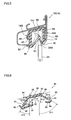
- Fig. 1 is an exterior side view schematically showing front and rear doors of a car to which a glass run channel assembly according to a first embodiment of the invention is attached;
- Fig. 2 is a side view schematically showing the entire structure of the glass run channel assembly according to the first embodiment
- Fig. 3 is a sectional view showing a cross-sectional shape of an upper side portion after extrusion molding of the glass run channel assembly according to the first embodiment
- Fig. 4 is a sectional view showing a cross-sectional shape of an upper side portion after extrusion molding of the glass run channel assembly according to the first embodiment, and a mounting direction of the upper side portion to an upper frame;
- Fig. 5 is a cross-sectional view taken along line V-V in Fig. 1 ;
- Fig. 6 is a sectional view showing a cross-sectional shape of a vertical side portion after extrusion molding of the glass run channel assembly according to the first embodiment
- Fig. 7 is a cross-sectional view taken along line VII-VII in Fig. 1 ;
- Fig. 8 is an explanatory view schematically showing an elastic force generated in each part of the glass run channel assembly according to the first embodiment after being mounted to a door frame;
- Fig. 9 is a sectional view showing a cross-sectional shape of an upper side portion after extrusion molding of the glass run channel assembly according to a second embodiment of the invention.
- Fig. 10 is a sectional view showing the cross-sectional shape of the upper side portion of the glass run channel assembly according to the second embodiment in the state of being mounted to the upper frame;
- Fig. 11 is a sectional view showing a cross-sectional shape of a vertical side portion after extrusion molding of the glass run channel assembly according to the second embodiment
- Fig. 12 is a sectional view showing the cross-sectional shape of the vertical side portion of the glass run channel assembly according to the second embodiment in the state of being mounted to a vertical frame;
- Fig. 13 is an explanatory view schematically showing an elastic force generated in each part of the glass run channel assembly according to the second embodiment after being mounted to a door frame.
- Fig. 1 is a side view schematically showing a front door 1A and a rear door 1B to be mounted to a car 1 (hereinafter referred to a sedan type passenger car).
- a car 1 hereinafter referred to a sedan type passenger car.
- the doors 1A and 1B to be mounted to the left side face of the car 1 is shown in this drawing, the door and glass run channel assembly of the same configuration (that is, bilaterally symmetrical) are also mounted as the right side face of the vehicle.
- the following description is description about only glass run channel assemblies to be mounted to the left front and rear doors 1A and 1B which are shown, and description about glass run channel assemblies to be mounted to right door panels is omitted.
- the front door 1A related to the first embodiment is generally comprised of a door outer panel 2A and a door inner panel (not shown) (hereinafter, both are generically abbreviated to "door panel 2A") which constitute a door body, and a door frame (front door frame) 10 formed above the panel 2A.
- the front door frame 10 related to the first embodiment is a made of a sash (that is, a long material which is formed by bending a steel strip in a predetermined cross-sectional shape by a cold roll forming method).
- the front door frame 10 has a vertical frame 12 arranged in a vertical direction along a center pillar 8 of the car 1, and an upper frame 14 which is formed integrally with an upper end of the vertical frame 12 and includes a portion of an inclination frame 13 which extends obliquely downward along a front pillar 4 from an upper end region of the vertical frame.
- the upper end of the vertical frame 12 and the terminal of the upper frame 14 on the side of the center pillar 8 are connected to each other by welding means, such as Tungsten-Inert Gas (TIG) welding, so as to intersect each other at a predetermined intersection angle.
- Tungsten-Inert Gas (TIG) welding so as to intersect each other at a predetermined intersection angle.
- this forms a corner portion, i.e., a corner frame 18 in which the upper end of the vertical frame 12 and the terminal of the upper frame 14 on the side of the center pillar 8 are connected integrally so as to intersect each other at a predetermined intersection angle.
- a partition frame 15 having a groove which extends in a vertical direction that is, a direction substantially orthogonal to a direction in which an upper periphery 2AA of the door panel 2A extends
- the partition frame 15 is fastened and fixed to the upper frame 14 (specifically, the inclination frame 13) by screws or the like via an L-shaped joint fitting (not shown).
- a glass run channel assembly 50 related to the first embodiment is mounted within an inside groove of the front door frame 10 (that is, the vertical frame 12, the upper frame 14 including the inclination frame 13, the partition frame 15, and the corner frame 18). The character and state of the glass run channel assembly will be described below.
- a triangular opening which is surrounded by the door panel upper periphery 2AA, the upper frame 14 (specifically, the inclination frame 13), and the partition frame 15, is formed in front side of the partition frame 15, and a front quarter window glass (that is, fixed window) 7A is fitted into the opening.
- a substantially rectangular window opening 9A which is surrounded by the door panel upper periphery 2AA, the upper frame 14 (including the inclination frame 13), the vertical frame 12, and the partition frame 15, is formed in the rear side of the partition frame 15.
- a windowpane 3A which is mounted to a windowpane lifting mechanism (not shown) provided within the door panel 2A, is mounted to the window opening 9A in a vertically movable manner while being guided by the glass run channel assembly 50 which will be described later.
- the rear door 1B related to the first embodiment is generally comprised of a door outer panel 2B and a door inner panel (not shown) (hereinafter, both are generically abbreviated to "door panel 2B") which constitute a door body, and a door frame (rear door frame) 20 formed above the panel 2B.
- the rear door frame 20 related to the first embodiment is made of the same sash as the front door frame 10.
- the rear door frame 20 has a vertical frame 22 arranged in a vertical direction along the center pillar 8 of the car 1, and an upper frame 24 which is formed integrally with an upper end of the vertical frame 22 and includes the portion of an inclination frame 23 which extends obliquely downward along a rear pillar 6 from an upper end region of the vertical frame 22.
- the upper end of the vertical frame 22 and the terminal of the upper frame 24 on the side of the center pillar 8 are connected to each other by welding means, such as TIG welding, so as to intersect each other at a predetermined intersection angle.
- this forms a corner portion, i.e., a corner frame 28 in which the upper end of the vertical frame 22 and the terminal of the upper frame 24 on the side of the center pillar 8 are connected integrally so as to intersect each other at a predetermined intersection angle.
- a partition frame 25 having a groove which extends in a vertical direction that is, a direction substantially orthogonal to a direction in which an upper periphery 2BB of the door panel 2B extends
- a partition frame 25 having a groove which extends in a vertical direction (that is, a direction substantially orthogonal to a direction in which an upper periphery 2BB of the door panel 2B extends) is detachably mounted from the region of the inclination frame 23 of the upper frame 24 which is slightly nearer to the rear.
- a glass run channel assembly 150 related to the first embodiment similar to the front door frame 10 is mounted within an inside groove of the rear door frame 20 (that is, the vertical frame 22, the upper frame 24 including the inclination frame 23, the partition frame 25, and the corner frame 28). The character and state of the glass run channel assembly will be described below.
- a triangular opening which is surrounded by the door panel upper periphery 2BB, the upper frame 24 (specifically, the inclination frame 23), and the partition frame 25, is formed in the rear side of the partition frame 25, and a rear quarter window glass (that is, fixed window) 7B is fitted into the opening.
- a substantially rectangular window opening 9B which is surrounded by the door panel upper periphery 2BB, the upper frame 24 (including the inclination frame 23), the vertical frame 22, and the partition frame 25, is formed in front of the partition frame 25.
- a windowpane 3B which is mounted to a windowpane lifting mechanism (not shown) provided within the door panel 2B, is mounted to the window opening 9B in a vertically movable manner while being guided by the glass run channel assembly 150 which will be described later.
- Fig. 2 is a side view schematically showing the whole glass run channel assembly 50 or 150 related to the first embodiment, which is mounted within the groove of the front door frame 10 or the rear door frame 20, which is described above.
- the glass run channel assembly 50 or 150 related to the first embodiment includes a long upper side portion 60 or 160, a long vertical side portion 80 or 180, an upper corner portion 100 or 200, a long partition side portion 120 and 220, and a lower corner portion 140 or 240.
- the glass run channel assembly 50 for the front door frame 10 and the glass run channel assembly 150 for the rear door frame 20 are almost the same in their general configuration, and there is no difference in the configuration which characterizes the invention. Accordingly, the following description will be given about the glass run channel assembly 50 for the front door frame 10, and since the description about the glass run channel assembly 150 for the rear door frame 20 is redundant, it is omitted.
- the long upper side portion 60 which is mounted along the upper frame 14 of the front door frame 10, is a long molded portion which is formed by extrusion-molding an elastic polymeric material.
- the upper side portion is formed from vulcanized elastic rubber (typically, a material composed mainly of ethylene propylene diene rubber (EPDM rubber)) such that the coefficient of static friction with the front door frame 10 becomes a predetermined value ( ⁇ 1).
- EPDM rubber ethylene propylene diene rubber
- the upper side portion is obtained by performing extrusion molding, using a rubber material for extrusion molding obtained by blending EPDM (here, 100 parts by mass), carbon black (here, 120 parts by mass), process oil (here, 80 parts by mass), various kinds of vulcanizing agents (here, 1 part by mass of sulfur), various kinds of fillers (here, 30 parts by mass of talc), various kinds of vulcanization accelerators (here, 2 parts by mass), and the like, and performing heat-treating (for example, about 200°C) to vulcanize the extrudate.
- EPDM here, 100 parts by mass
- carbon black here, 120 parts by mass
- process oil here, 80 parts by mass
- various kinds of vulcanizing agents here, 1 part by mass of sulfur
- various kinds of fillers here, 30 parts by mass of talc
- various kinds of vulcanization accelerators here, 2 parts by mass
- heat-treating for example, about 200°C
- a molded body whose static friction coefficient ( ⁇ 1) is about equal to or more than 1.1 and less than 1.7 (typically 1.4 ⁇ 0.1) can be formed.
- the vertical side portion 80 and the partition side portion 120 which are respectively mounted along the vertical frame 12 and the partition frame 15 of the front door frame 10 are long molded portion which are formed by extrusion-molding an elastic polymeric material.
- the vertical side portion and the partition side portion are formed from an olefin system thermoplastic elastomer (TPO) such that the coefficient of static friction with the front door frame 10 becomes a value ( ⁇ 2) larger than the above static friction coefficient ⁇ 1 in the upper side portion 60.
- TPO olefin system thermoplastic elastomer
- the vertical side portion and the partition side portion are preferably obtained using various TPO products (for instance, TPO materials sold by AES Japan, Inc. (for example, trade name: Santoprene (registered trademark) 121-67W)) which are commercially available.
- a molded body whose static friction coefficient ( ⁇ 2) is about equal to or more than 1.7 and less than 2.0 (typically 1.8 ⁇ 0.1) can be formed.
- the upper corner portion 100 which is mounted along the corner frame 18 of the front door frame 10 and integrally connects the upper side portion 60 and the vertical side portion 80
- the lower corner portion 140 which connects the upper side portion 60 and the partition side portion 120, are molded portions formed by injection-molding an elastic polymeric material.
- the molding and connection of the corner portions can be simultaneously performed by placing the corner portion within an injection molding mold while the terminals (specifically, the terminal of the upper side portion 60 and the terminal of the vertical side portion 80, or the terminal of the upper side portion 60 and the terminal of the partition side portion 120) of long moldings to be connected are made to intersect each other a predetermined intersection angle at a predetermined distance (space) from each other, and injecting a heated and melted thermoplastic elastomer material (for example, TPO) into a space within the injection molding mold.
- a heated and melted thermoplastic elastomer material for example, TPO
- the corner portion 100 or 140 which has been molded in a predetermined shape in advance may be prepared, and the corner portion may be connected to the terminals (specifically, the terminal of the upper side portion 60 and the terminal of the vertical side portion 80 or the terminal of the upper side portion 60 and the terminal of the partition side portion 120) of long moldings to be connected by a suitable adhesive.
- FIG. 3 The cross-sectional shape of the upper side portion 60 after extrusion molding (that is, before being mounted to the door frame 10) is shown in Figs. 3 and 4 .
- the cross-sectional shape of the upper frame 14 which is a portion of the front door frame 10 is shown in Fig. 4 .
- Fig. 5 is a sectional view taken along line V-V of Fig. 1 showing a state where the upper side portion 60 is mounted to the upper frame 14.
- the upper frame 14 is formed from steel which is bent such that an interior side wall 14G and an exterior side wall 14A are arranged substantially parallel to each other in the width direction of the car, and a groove 14S is formed between the two side walls 14A and 14G along the frame.
- the periphery of the groove 14S within the upper frame 14 is formed by the exterior side wall 14A, the interior side wall 14G, and a bottom wall 14J.
- the planar direction of the bottom wall 14J and the lifting direction of the windowpane 3A are not orthogonal to each other, but are inclined such that the exterior of the bottom wall 14J is at a higher position than the interior thereof (that is, such that the intersection angle between the lifting direction of the windowpane 3A and the exterior of the bottom wall 14J is an obtuse angle).
- the portion of the exterior side wall 14A near the bottom wall 14J is formed as an enlarged wall 14B which is recessed more than an inner peripheral wall 14D near an opening of the exterior side wall 14A such that the space (the distance between the exterior side wall 14A and the interior side wall 14G) within the groove is enlarged more than the vicinity of the opening, and a stepped portion 14C is formed between the enlarged wall 14B and the inner peripheral wall 14D.
- the portion of the bottom wall 14J near the interior side wall 14G is formed as an enlarged wall 14H which is recessed more than an inner peripheral wall 14E near an opening of the interior side wall 14G, and a stepped portion 14F is formed between the enlarged wall 14H and the inner peripheral wall 14E.
- the upper side portion 60 of the glass run channel assembly 50 related to the first embodiment generally has a bottom wall portion 66 arranged in a position which faces an outer peripheral end face 3AA of the windowpane 3A, an interior side wall portion 63 which protrudes via an interior connection 65 from an interior end in a width direction of the bottom wall portion 66, and an exterior side wall portion 69 which protrudes via an exterior connection 67 from an exterior end in the width direction of the bottom wall portion 66.
- the interior connection 65 and the exterior connection 67 are formed so as to have a smaller thickness than the adjacent bottom wall portion 66 or both the interior and exterior side wall portions 63 and 69 such that they can be bent when being mounted to the door frame 10 (refer to opposed arrows in Fig. 3 ).
- an extrusion-molded body which constitutes the upper side portion 60 has an expanded, substantially U-shaped constant cross-sectional shape by the bottom wall portion 66 and both the interior and exterior side wall portions 63 and 69.
- an interior seal lip 61 and an exterior seal lip 70 which extend in a folded-back shape toward the bottom wall portion 66 integrally from protruding tips of the interior side wall portion 63 and the exterior side wall portion 69 while holding a space to the side wall portions 63 and 69 are provided.
- an interior engagement projection ridge 64 is formed at the end of the interior side wall portion 63 near the bottom wall portion 66 so as to project outward.
- an interior tip projection 62 is formed at the end of the interior side wall portion 63 near the interior seal lip 61 so as to project outward.
- an exterior engagement projection ridge 68 is formed at the end of the exterior side wall portion 69 near the bottom wall portion 66 so as to project outward.
- an exterior tip projection 71 is formed at the end of the exterior side wall portion 69 near the exterior seal lip 70 so as to project outward.
- the upper side portion 60 of the glass run channel assembly 50 related to the first embodiment is extrusion-molded such that the relative positional relationship, i.e., angle, of the aforementioned respective portions is adjusted as indicated by ⁇ in Fig. 3 .
- the cross-sectional shape after extrusion molding is adjusted such that an angle ⁇ 3 between the exterior side wall portion 69 and the exterior seal lip 70 is about 40°, an angle ⁇ 4 between the interior side wall portion 63 and the interior seal lip 61 is about 40°, an angle ⁇ 5 between the exterior side wall portion 69 and the exterior engagement projection ridge 68 is about 35°, and the angle 66 between the interior side wall portion 63 and the interior engagement projection ridge 64 is about 35°.
- each of the interior side wall portion 63 and the exterior side wall portion 69 is changed to a U-shape (here, a U-shape in which the angle ⁇ between the bottom wall portion 66 and the exterior side wall portion 69 after mounting to the upper frame 14 is about 80°, and the angle ⁇ between the bottom wall portion 66 and the interior side wall portion 63 is about 100°) after being mounted (refer to Fig.
- such elastic deformation angles are adjusted such that a predetermined elastic force (fl) is obtained in portions where the interior side wall portion 63 and the exterior side wall portion 69 contact the upper frame after mounting to the door frame 10 (the upper frame 14).
- the elastic deformation angle ⁇ 1 of the exterior side wall portion 69 is set to about 65°
- the elastic deformation angle ⁇ 2 of the interior side wall portion 63 is set to about 45°.
- the thickness of the exterior connection 67 of the aforementioned upper side portion 60 is made larger than the thickness of the exterior connection 87 of the vertical side portion 80 which will be described later, and the thickness of the interior connection 65 of the upper side portion 60 is also made larger than the thickness of the interior connection 85 of the vertical side portion 80.
- the cross-sectional shape of the upper side portion 60 related to the first embodiment is adjusted such that the frictional force per unit length obtained by multiplying the coefficient ⁇ 1 of static friction with the upper frame 14 by the elastic force fl is relatively larger than the frictional force per unit length obtained by multiplying the coefficient ⁇ 2 of static friction of the vertical side portion 80 (the same is true on the partition side portion 120), which will be described later, with the vertical frame 12 by the elastic force f2.
- the upper side portion 60 of the above configuration is mounted into the groove 14S upward from below the upper frame 14 while being elastically deformed from the expanded U-shape to the reduced U-shape as described above due to the elastic deformation that the interior and exterior connections 65 and 67 are curved in a bent shape.
- the interior side wall portion 63 and the exterior side wall portion 69 which have been elastically deformed are pressed against the interior side wall 14G and the exterior side wall 14A, respectively, by the predetermined elastic force (fl).
- the upper side portion 60 related to the first embodiment is formed from a vulcanized elastic rubber (typically, a material composed mainly of ethylene propylene diene rubber (EPDM rubber)) as described above.
- EPDM rubber ethylene propylene diene rubber
- the upper side portion is made of elastic rubber whose static friction coefficient is lower than that of a conventional glass run channel assembly which is molded from TPO. Therefore, the mounting operation to the door frame 10 becomes easy, and the load (fatigue) given to a mounting operator can be made small.
- the operation of mounting a glass run channel assembly upward from below the upper frame 14 is the operation which forces a burden upon an operator more than a case where the glass run channel assembly is mounted downward from above or laterally.
- the upper side portion 60 is made of elastic rubber whose static friction coefficient is low, it becomes easy to mount the glass run channel assembly upward from below the upper frame 14.
- the upper side portion 60 is made of the above elastic rubber with smaller creep deformation unlike the glass run channel which is molded from TPO in whole. Therefore, the frictional force generated between the upper side portion 60 and the upper frame 14 (including the inclination frame 13) can be kept larger than that of a glass run channel which is molded from TPO in whole after lapse of predetermined time after mounting. Accordingly, in this mounting part, occurrence of an unexpected positional deviation of the glass run channel assembly 50 accompanying the operation of the windowpane 3A which moves up and down can be prevented over a prolonged period of time. In addition, as shown in Fig.
- a low friction material layer 72 whose static friction coefficient is lower than that of the bottom wall portion 66 be continuously formed in a longitudinal direction in the portion of the bottom wall portion 66 of the upper side portion 60 which faces the outer peripheral end face 3AA of the windowpane 3A.
- a low friction material layer 73, 74 whose static friction coefficient is low be continuously formed in the longitudinal direction even in the outer surfaces of the interior and exterior seal lips which can contact the windowpane 3A shown in Fig. 5 .
- coating such as urethane coating
- the preferable range of the coating is shown by a broken line in Fig. 3 .
- the interior engagement projection ridge 64 and the exterior engagement projection ridge 68 are fitted into the interior enlarged wall 14H and the exterior enlarged wall 14B, respectively, by elastic rebounding during mounting, and the stepped portions 14C and 14F become hindrances, so that slip-off of the upper side portion 60 can be prevented more reliably. Additionally, according to the upper side portion 60 related to the first embodiment, a gap created between the interior side wall 14G and exterior side wall 14A of the upper frame 14 and the upper side portion 60 can be concealed by the interior tip projection 62 and the exterior tip projection 71 after mounting.
- Fig. 6 The cross-sectional shape of the vertical side portion 80 after extrusion molding (that is, before being mounted to the door frame 10) is shown in Fig. 6 .
- Fig. 7 is a sectional view taken along line VII-VII of Fig. 1 showing a state where the vertical side portion 80 is mounted to the vertical frame 12.
- illustration of the vertical frame 22 of the rear door 1B is omitted in Fig. 7 .
- the vertical frame 12 has the same structure as the aforementioned upper frame 14, and is formed from steel strip which is bent such that the interior side wall 12G and the exterior side wall 12A are arranged substantially parallel to each other in the width direction of the car, and a groove 12S is formed between the two side walls 12A and 12G along the frame. That is, the periphery of the groove 12S within the vertical frame 12 is constituted by the exterior side wall 12A, the interior side wall 12G, and a bottom wall 12J.
- planar direction of the bottom wall 12J and the planar direction of the windowpane 3A are not orthogonal to each other, but are inclined such that the exterior of the bottom wall 12J is located nearer the rear of the vehicle than the interior thereof (that is, such that the intersection angle between the planar direction of the windowpane 3A and the exterior of the bottom wall 12J is an obtuse angle).
- the portion of the exterior side wall 12A near the bottom wall 12J is formed as an enlarged wall 12B which is recessed more than an inner peripheral wall 12D near an opening of the exterior side wall 12A such that the space (the distance between the exterior side wall 12A and the interior side wall 12G) within the groove is enlarged more than the vicinity of the opening, and a stepped portion 12C is formed between the enlarged wall 12B and the inner peripheral wall 12D.
- the portion of the interior side wall 12G near the bottom wall 12J is formed as an enlarged wall 12H which is recessed more than an inner peripheral wall 12E near an opening of the interior side wall 12G, and a stepped portion 12F is formed between the enlarged wall 12H and the inner peripheral wall 12E.
- the vertical side portion 80 of the glass run channel assembly 50 related to the first embodiment generally has a bottom wall portion 86 arranged in a position which faces an outer peripheral end face 3AA of the windowpane 3A, an interior side wall portion 83 which protrudes via an interior connection 85 from an interior end in a width direction of the bottom wall portion 86, and an exterior side wall portion 89 which protrudes via an exterior connection 87 from an exterior end in the width direction of the bottom wall portion 86.
- the interior connection 85 and the exterior connection 87 are formed so as to have a smaller thickness than the adjacent bottom wall portion 86 or both the interior and exterior side wall portions 83 and 89 such that they can be bent when being mounted on the door frame 10 (refer to opposed arrows in Fig. 6 ).
- an extrusion-molded body which constitutes the vertical side portion 80 has an expanded, substantially U-shaped constant cross-sectional shape by the bottom wall portion 86 and both the interior and exterior side wall portions 83 and 89.
- an interior seal lip 81 and an exterior seal lip 90 which extend in a folded-back shape toward the bottom wall portion 86 integrally from protruding tips of the interior side wall portion 83 and the exterior side wall portion 89 while holding a space to the side wall portions 83 and 89 are provided.
- an interior engagement projection ridge 84 is formed at the end of the interior side wall portion 83 near the bottom wall portion 86 so as to project outward.
- an interior tip projection 82 is formed at the end of the interior side wall portion 83 near the interior seal lip 81 so as to project outward.
- an exterior engagement projection ridge 88 is formed at the end of the exterior side wall portion 89 near the bottom wall portion 86 so as to project outward.
- an exterior tip projection 91 is formed at the end of the interior side wall portion 89 near the seal lip 90 so as to project outward.
- low friction material layers 92, 93, and 94 whose static friction coefficients are lower than those of the bottom wall portion 86, the interior seal lip 81, and the exterior seal lip 90 are continuously formed in a longitudinal direction in the portion of the bottom wall portion 86 of the vertical side portion 80 which faces the outer peripheral end face 3AA of the windowpane 3A, and in the outer surfaces of the interior seal lip 81 and the exterior seal lip 90.
- a material which constitutes the low friction material layers 92, 93, and 94 for example, compositions obtained by mixing polypropylene, ultrahigh molecular weight polyethylene, EPDM, silicone oil, etc. can be included.
- the vertical side portion 80 of the glass run channel assembly 50 related to the first embodiment is extrusion-molded such that the relative positional relationship, i.e., angle, of the aforementioned respective portions is adjusted as indicated by ⁇ in Fig. 6 .
- the cross-sectional shape after extrusion molding is adjusted such that an angle ⁇ 13 between the exterior side wall portion 89 and the exterior seal lip 90 is about 40°, an angle ⁇ 14 between the interior side wall portion 83 and the interior seal lip 81 is about 40°, an angle ⁇ 15 between the exterior side wall portion 89 and the exterior engagement projection ridge 88 is about 45°, and the angle ⁇ 16 between the interior side wall portion 83 and the interior engagement projection ridge 84 is about 50°.
- each of the interior side wall portion 83 and the exterior side wall portion 89 is changed to a U-shape (here, a U-shape in which the angle ⁇ ' between the bottom wall portion 86 and the exterior side wall portion 89 after mounting to the vertical frame 12 is about 80°, and the angle ⁇ ' between the bottom wall portion 86 and the interior side wall portion 83 is about 100°) in which the expansion degree of the expanded U-shape before the mounting is reduced with the bent elastic deformation of the connections 85 and 87 after being mounted (refer to Fig.
- such elastic deformation angles are adjusted such that a predetermined elastic force (f2) is obtained in portions where the exterior side wall portion 89 and the interior side wall portion 83 contact the vertical frame after mounting to the door frame 10 (the vertical frame 12).
- the elastic deformation angle ⁇ 11 of the exterior side wall portion 89 is set to about 55°
- the elastic deformation angle ⁇ 12 of the interior side wall portion 83 is set to about 30°.
- the respective elastic deformation angles ⁇ 2 and ⁇ 1 of the interior side wall portion 63 and the exterior side wall portion 69 in the upper side portion 60 are set so as to be larger than the elastic deformation angles ⁇ 12 and ⁇ 11 of the interior side wall portion 83 and the exterior side wall portion 89 in the vertical side portion 80. That is, the cross-sectional shapes of the upper side portion 60 and the vertical side portion 80 are adjusted so as to realize ⁇ 1> ⁇ 11 and ⁇ 2> ⁇ 12.
- the cross-sectional shapes of the upper side portion 60 and the vertical side portion 80 may be adjusted such that a sum of the elastic deformation angles ⁇ 1 + ⁇ 2 is larger than a sum of the elastic deformation angles ⁇ 11 + ⁇ 12.
- the cross-sectional shapes of the upper side portion 60 and the vertical side portion 80 are adjusted such that the frictional force per unit length obtained by multiplying the coefficient ⁇ 2 of static friction of the vertical side portion 80 with the vertical frame 12 by the elastic force f2 is relatively smaller than the frictional force per unit length obtained by multiplying the coefficient ⁇ 1 of static friction of the aforementioned upper side portion 60 with the upper frame 14 by the elastic force fl.
- the vertical side portion 80 of the above configuration is laterally mounted into the groove 12S of the vertical frame 12 while being elastically deformed from the expanded U-shape to the reduced U-shape as described above due to the elastic deformation that the interior and exterior connections 85 and 87 are curved in a bent shape.
- the interior side wall portion 83 and the exterior side wall portion 89 which have been elastically deformed are pressed against the interior side wall 12G and the exterior side wall 12A, respectively, by the predetermined elastic force (f2).
- the vertical side portion 80 related to the first embodiment is formed from a TPO material whose specific gravity is smaller than rubber which constitutes the upper side portion 60, a reduction in weight can be achieved compared with a glass run channel assembly which is molded from rubber in whole. That is, in addition to the prevention of positional deviation of the glass run channel assembly 50 in the vertical frame 12, it is possible to enjoy merits (an improvement in efficiency of conveyance, a reduction in the weight of a vehicle, etc.) by virtue of the reduction in weight.
- the interior engagement projection ridge 84 and the exterior engagement projection ridge 88 are fitted into the interior enlarged wall 12H and the exterior enlarged wall 12B, respectively, by elastic rebounding after mounting, and the stepped portions 12C and 12F become hooks, so that slip-off of the vertical side portion 80 can be prevented more reliably.
- a gap created between the interior side wall 12G and exterior side wall 12A of the vertical frame 12 and the vertical side portion 80 can be concealed by the interior tip projection 82 and the exterior tip projection 91 after mounting.
- the upper side portion 60 and the vertical side portion 80 are formed from materials which are different from each other, and when being mounted along the door frame 10 as described above, both the upper side portion 60 and the vertical side portion 80 are arranged so as to be changed to a shape in which the expansion degree of the above expanded U-shape before mounting in the interior side wall portion 63 or 83 and the exterior side wall portion 69 or 89 is reduced by the elastic deformation of the connections 65, 67, 85, and 87 which are elastically deformed in a bent shape during mounting to the door frame.
- the cross-sectional shapes of the upper side portion and the vertical side portion are adjusted such that a predetermined elastic force f2 is generated in portions where the interior side wall portion 83 and the exterior side wall portion 89 of the vertical side portion 80 contact the vertical frame 12, and a predetermined elastic force fl is generated in portions where the interior side wall portion 63 and the exterior side wall portion 69 of the upper side portion 60 contacts the upper frame 14.
- each of the upper side portion and the vertical side portion is adjusted such that the friction force per unit length obtained by multiplying the coefficient ⁇ 1 of static friction of the upper side portion 60 with the upper frame 14 by the elastic force fl is larger than the frictional force per unit length obtained by multiplying the coefficient ⁇ 2 of static friction of the vertical side portion 80 with the vertical frame 12 by the elastic force f2.
- This relationship is typically shown in Fig. 8 .
- Arrows to which symbols including the capital F in the drawings are given schematically represent the magnitude and direction of elastic forces in respective parts generated after mounting to the door frame vectorially. It is easily understood by the comparison between the magnitudes of vectors (arrow) from this drawing that the elastic force f1 (equivalent to F1 and F2 in Fig.
- the glass run channel assembly 50 which can realize both achievement of a reduction in weight compared with a glass run channel which is extrusion-molded in whole by using an extrusion molding material including a rubber material, and prevention of occurrence of positional deviation in the longitudinal direction of the door frame after being mounted to a given position of the door frame.
- At least one of the elastic deformation angles of the interior side wall portion 63 and the exterior side wall portion 69 in the upper side portion 60 is set so as to be larger than the elastic deformation angles of the interior side wall portion 83 and the exterior side wall portion 89 in the corresponding vertical side portion 80 (here, both ⁇ 1> ⁇ 11 and ⁇ 2> ⁇ 12). For this reason, a high frictional force can be generated between the upper side portion 60 and the upper frame 14 including the above inclination frame 13, and occurrence of an unexpected positional deviation of the glass run channel assembly 50 accompanying the operation of the windowpane 3A which moves up and down can be prevented.
- the glass run channel assembly 50 related to the first embodiment is molded such that at least one intersection angle (both intersection angles in the first embodiment) of the intersection angle between the bottom wall portion 66 of the upper side portion 60, and the exterior side wall portion 69, and the intersection angle between the bottom wall portion 66 of the upper side portion 60, and the interior side wall portion 63 is an obtuse angle in a state before being mounted to the door frame 10. For this reason, a high frictional force can be generated between the upper side portion 60 and the upper frame 14 including the above inclination frame 13, and occurrence of an unexpected positional deviation of the glass run channel assembly 50 accompanying the operation of the windowpane 3A which moves up and down can be prevented.
- the glass run channel assembly 50 related to the first embodiment is formed such that the thickness of the exterior connection 67 of the upper side portion 60 is larger than the thickness of the exterior connection 87 of the vertical side portion 80 and/or the thickness of the interior connection 65 of the upper side portion 60 is larger than the thickness of the interior connection 85 of the vertical side portion 80 (both thicknesses are larger in the first embodiment). For this reason, a larger elastic force than that in the vertical side portion 80 can be generated in the upper side portion 60, a high frictional force can be generated between the upper side portion 60 and the upper frame 14 including the above inclination frame 13, and occurrence of an unexpected positional deviation of the glass run channel assembly 50 accompanying the operation of the windowpane 3A which moves up and down can be prevented.
- the upper side portion 60 and the vertical side portion 80, and the upper side portion 60 and the partition side portion 120 are connected integrally in the corner portions 100 and 140, respectively, in order to maintain integrity in its longitudinal direction.
- the upper corner portion 100 is formed such that the intersection angle between the bottom wall portion and the exterior side wall portion and the intersection angle between the bottom wall portion and the interior side wall portion in the upper corner portion 100 change so as to become gradually small from the same intersection angle as the upper side portion 60 to the same intersection angle as the intersection angle of the vertical side portion 80 as it approaches from the upper side portion 60 toward the vertical side portion 80.
- the lower corner portion 140 is also formed such that the intersection angles change so as to become gradually small from the same intersection angle as the upper side portion 60 to the same intersection angle as the intersection angle of the partition side portion 120 as it approaches from the upper side portion 60 toward the partition side portion 120.
- the upper side portion 60 and the vertical side portion 80, and the upper side portion 60 and the partition side portion 120 are connected integrally in the corner portions 100 and 140, respectively, in order to maintain integrity in its longitudinal direction.
- the upper corner portion 100 is formed such that the elastic deformation angles of the interior side wall portion and the exterior side wall portion in the upper corner portion 100 when being mounted along the door frame 10 change so as to become gradually small from the same elastic deformation angle as the upper side portion 60 to the same elastic deformation angle as the elastic deformation angle of the vertical side portion 80 as it approaches from the upper side portion 60 toward the vertical side portion 80.
- the lower corner portion 140 is also formed such that the elastic deformation angles change so as to become gradually small from the same elastic deformation angle as the upper side portion 60 to the same elastic deformation angle as the elastic deformation of the partition side portion 120 as it approaches from the upper side portion 60 toward the partition side portion 120.
- the upper corner portion 100 and the lower corner portion 140 By forming the upper corner portion 100 and the lower corner portion 140 in this way, it is possible to provide a glass run channel assembly having excellent integrity in the corner portions 100 and 140 in the longitudinal direction, and in the vicinity thereof (that is, the end of an adjacent extrusion-molded portion near the corner portion), and easy mounting operation to the door frame 10. Additionally, unexpected deformation does not occur in the corner portion during mounting operation. Accordingly, it is possible to stably mount the glass run channel assembly 50 to the whole frame including the corner portion (that is, the corner frame 18 and the partition frame 15) of the door frame 10.
- the glass run channel assembly 250 related to the second embodiment is a glass run channel assembly with which is mounted to a panel door frame 310 molded integrally with a door panel by press working.
- Fig. 9 is a sectional view showing the cross-sectional shape of the upper side portion 260 of the glass run channel assembly 250 related to the second embodiment.
- Fig. 10 is a cross-sectional view showing the state where the upper side portion 260 is mounted into a groove 314S of the upper frame 314 of the door frame 310 (although the front door frame is shown here, the same is true on the rear door frame).
- the upper frame 314 is formed such that an interior side wall 314G and an exterior side wall 314A are arranged substantially parallel to each other in the width direction of the car.
- An L-shaped stopper member 314D is fixed by welding to the interior side wall 314G.
- a groove 314S is formed between the exterior side wall 314A and the stopper member 314D along the frame.
- the periphery of the groove 314S within the upper frame 314 is constituted by the exterior side wall 314A, an interior side wall of the stopper member 314D, and a bottom wall 314J of the stopper member 314D. Additionally, the tip of the exterior side wall 314A is bent toward the groove 314S along the longitudinal direction to form an engagement tip 314C.
- the upper side portion 260 of the glass run channel assembly 250 related to the second embodiment generally has a bottom wall portion 266 arranged in a position which faces an outer peripheral end face 3AA (refer to Fig. 5 ) of the windowpane 3A, an interior side wall portion 263 which protrudes via an interior connection 265 from an interior end in a width direction of the bottom wall portion 266, and an exterior side wall portion 269 which protrudes via an exterior connection 267 from an exterior end in the width direction of the bottom wall portion 266.
- Fig. 5 the bottom wall portion 266 arranged in a position which faces an outer peripheral end face 3AA (refer to Fig. 5 ) of the windowpane 3A
- an interior side wall portion 263 which protrudes via an interior connection 265 from an interior end in a width direction of the bottom wall portion 266, and an exterior side wall portion 269 which protrudes via an exterior connection 267 from an exterior end in the width direction of the bottom wall portion 266.
- the interior connection 265 and the exterior connection 267 are formed so as to have a smaller thickness than the adjacent bottom wall portion 266 or both the interior and exterior side wall portions 263 and 269 such that they can be bent when being mounted on the door frame 310 (refer to opposed arrows in Fig. 9 ).
- the upper side portion 260 is formed from vulcanized elastic rubber (typically, a material composed mainly of ethylene propylene diene rubber (EPDM rubber)) such that the coefficient of static friction with the door frame 310 (upper frame 314) becomes a predetermined value ( ⁇ 1).
- vulcanized elastic rubber typically, a material composed mainly of ethylene propylene diene rubber (EPDM rubber)
- the long upper side portion is obtained by performing extrusion, using a rubber material for extrusion obtained by blending EPDM (here, 100 parts by mass), carbon black (here, 120 parts by mass), process oil (here, 80 parts by mass), various kinds of vulcanizing agents (here, 1 part by mass of sulfur), various kinds of fillers (here, 30 parts by mass of talc), various kinds of vulcanization accelerators (here, 2 parts by mass), and the like, and performing heat-treating (for example, about 200°C) to vulcanize the extrudate.
- EPDM here, 100 parts by mass
- carbon black here, 120 parts by mass
- process oil here, 80 parts by mass
- various kinds of vulcanizing agents here, 1 part by mass of sulfur
- various kinds of fillers here, 30 parts by mass of talc
- various kinds of vulcanization accelerators here, 2 parts by mass
- heat-treating for example, about 200°C
- an extrusion-molded body which constitutes the upper side portion 260 has an expanded, substantially U-shaped constant cross-sectional shape by the bottom wall portion 266 and both the interior and exterior side wall portions 263 and 269.
- an interior seal lip 261 and an exterior seal lip 270 which extend in a folded-back shape toward the bottom wall portion 266 integrally from protruding tips of the interior side wall portion 263 and the exterior side wall portion 269 while holding a space to the side wall portions 263 and 269 are provided.
- an exterior engagement projection ridge 268 is formed at the end of the exterior side wall portion 269 near the bottom wall portion 266 so as to project outward.
- an interior engagement projection ridge 264 is formed at the outer surface near the protruding tip of the interior side wall portion 263 so as to project outward.
- concealing lips are respectively and integrally formed at protruding tips of the exterior side wall portion 269 and interior side wall portion 263 of the upper side portion 260.
- These concealing lips extend toward the side opposite to the seal lips 261 and 270 in a folded-back shape while holding a space to the side wall portions, cover the inner peripheral edge (that is, the side wall 314A or 314G) of the door frame 310 (the upper frame 314) from the outside when being mounted to the door frame 310 (the upper frame 314), and is able to be elastically deformed to grip the inner peripheral edge (the side wall 314A or 314G) in conformity with the side wall portion 263 or 269 when being mounted to the door frame 310.
- the upper side portion 260 of the glass run channel assembly 250 related to the second embodiment is extrusion-molded such that the relative positional relationship, i.e., angle, of the aforementioned respective constituent portions is adjusted as indicated by ⁇ in Fig. 9 .
- the cross-sectional shape after extrusion is adjusted such that the angle ⁇ 103 between the exterior side wall portion 269 and the exterior seal lip 270 becomes about 35° and the angle ⁇ 104 between the interior side wall portion 263 and the interior seal lip 261 becomes 35°.
- each of the interior side wall portion 263 and the exterior side wall portion 269 is deformed to a U-shape in which the expansion degree of the expanded U-shape before the mounting is reduced with the bent elastic deformation of the connections 265 and 267 (here, a U-shape in which the angle ⁇ between the bottom wall portion 266 and the exterior side wall portion 269 after mounting to the upper frame 314 is about 90°, and the angle ⁇ between the bottom wall portion 266 and the interior side wall portion 263 is considering it as the shape of a U-shape which is about 90°) after being mounted (refer to Fig.
- such an elastic deformation angle is adjusted such that a predetermined elastic force (f1) is obtained in portions where the interior side wall portion 263 and the exterior side wall portion 269 contact the upper frame after mounting to the door frame 310 (the upper frame 314).
- the elastic deformation angle ⁇ 101 of the exterior side wall portion 269 is set to about 50°
- the elastic deformation angle ⁇ 102 of the interior side wall portion 263 is set to about 50°.
- the thickness of the exterior connection 267 of the aforementioned upper side portion 260 is made larger than the thickness of the exterior connection 287 of the vertical side portion 280 which will be described later, and the thickness of the interior connection 265 of the upper side portion 260 is also made larger than the thickness of the interior connection 285 of the vertical side portion 280.
- the cross-sectional shape of the upper side portion 260 related to the second embodiment is adjusted such that the frictional force per unit length obtained by multiplying the coefficient ⁇ 1 of static friction of the upper side portion 260 with the upper frame 314 by the elastic force fl is relatively larger than the frictional force per unit length obtained by multiplying the coefficient ⁇ 2 of static friction of the vertical side portion 280 (the same is true on the partition side portion (not shown)), which will be described later, with the vertical frame 312 by the elastic force f2.
- the upper side portion 260 of the above configuration is mounted into the groove 3145 upward from below the upper frame 314 while being elastically deformed from the expanded U-shape to the reduced U-shape as described above due to the elastic deformation that the interior and exterior connections 265 and 267 are curved in a bent shape.
- the interior side wall portion 263 and the exterior side wall portion 269 which have been elastically deformed are pressed against the interior side wall 314G and the exterior side wall 314A, respectively, by the predetermined elastic force (fl).
- the upper side portion 260 related to the second embodiment is formed from a vulcanized elastic rubber (typically, a material composed mainly of ethylene propylene diene rubber (EPDM rubber)) as described above.
- EPDM rubber ethylene propylene diene rubber
- the upper side portion is made of elastic rubber whose static friction coefficient is lower than that of a conventional glass run channel assembly which is molded from TPO in whole. Therefore, the mounting operation to the door frame 310 becomes easy, and the load (fatigue) given to a mounting operator can be made small.
- the operation of mounting a glass run channel assembly upward from below the upper frame 314 is the operation which forces a burden upon an operator more than a case where the glass run channel assembly is mounted downward from above or laterally.
- the upper side portion 260 is made of elastic rubber whose static friction coefficient is low, it becomes easy to mount the glass run channel assembly upward from below the upper frame 314.
- the upper side portion 260 is made of the above elastic rubber with smaller creep deformation unlike the glass run channel which is molded from TPO. Therefore, the frictional force generated between the upper side portion 260 and the upper frame 314 (including the inclination frame portion (refer to Fig. 1 ) which is not shown) can be kept larger than that of a glass run channel which is molded from TPO in whole after lapse of predetermined time after mounting. Accordingly, in this mounting part, occurrence of an unexpected positional deviation of the glass run channel assembly 250 accompanying the operation of the windowpane 3A which moves up and down can be prevented over a prolonged period of time.
- a low friction material layer (not shown) whose static friction coefficient is lower than that of the bottom wall portion 266 be continuously formed in a longitudinal direction in the portion of the bottom wall portion 266 of the upper side portion 260 which faces the outer peripheral end face 3AA of the windowpane 3A.
- a low friction material layer whose static friction coefficient is low be continuously formed in the longitudinal direction even in the outer surfaces of the interior and exterior seal lips 261 and 270 which can contact the windowpane 3A. This is the same as the first embodiment.
- the above interior engagement projection ridge 264 contacts the inner surface of the stopper member 314D by elastic rebounding after mounting.
- the exterior engagement projection ridge 268 contacts the exterior side wall 314A, and engages the engagement tip 314C. This can prevent slip-off of the upper side portion 260 from the upper frame 314 more reliably.
- the exterior side wall portion 269 and the interior side wall portion 263 can be drawn near to the exterior inner peripheral edge (that is, the exterior side wall 314A) and interior inner peripheral edge (that is, the inner surface of the stopper member 314D) of the door frame 310 (the upper frame 314), respectively, by the elastic force generated by the elastic deformation of the above concealing lips 271 and 262.
- This can generate much larger elastic force (in other words, pressing force) (refer to Fig. 13 which will be described later) in addition to the elastic forces of the exterior side wall portion 269 and interior side wall portion 263.
- a high frictional force can be generated between the upper side portion 260 and the upper frame 314 of the door frame 310, and occurrence of an unexpected positional deviation of the glass run channel assembly 250 accompanying the operation of the windowpane which moves up and down can be prevented more reliably.
- the concealing lips 271 and 262 can conceal a gap created between the interior side wall 314G and the exterior side wall 314A of the upper frame 314, and the upper side portion 260.
- Fig. 11 The cross-sectional shape of the vertical side portion 280 after extrusion molding (that is, before being mounted to the door frame 310) is shown in Fig. 11 .
- Fig. 12 is a sectional view showing a state where the vertical side portion 280 is mounted to the vertical frame 312.
- the vertical frame 312 is formed such that an interior side wall 312G and an exterior side wall 312A are arranged substantially parallel to each other in the width direction of the car, and a groove 3125 is formed between the two side walls 312A and 312G along the frame.
- the vertical side portion 280 of the glass run channel assembly 250 related to the second embodiment generally has a bottom wall portion 286 arranged in a position which faces an outer peripheral end face 3AA of the windowpane 3A, an interior side wall portion 283 which protrudes via an interior connection 285 from an interior end in a width direction of the bottom wall portion 286, and an exterior side wall portion 289 which protrudes via an exterior connection 287 from an exterior end in the width direction of the bottom wall portion 286.
- the interior connection 285 and the exterior connection 287 are formed so as to have a smaller thickness than the adjacent bottom wall portion 286 or both the interior and exterior side wall portions 283 and 289 such that they can be bent when being mounted on the door frame 310 (the vertical frame 312) (refer to opposed arrows in Fig. 11 ).
- the vertical side portion 280 is formed from an olefin system thermoplastic elastomer (TPO) such that the coefficient of static friction with the front door frame 310 becomes a larger value ( ⁇ 2) than the above static friction coefficient ⁇ 1 in the upper side portion 260.
- TPO thermoplastic elastomer
- the vertical side portion and the partition side portion are preferably obtained using various TPO products (for instance, TPO materials sold by AES Japan, Inc. (for example, trade name: Santoprene (registered trademark) 121-67W)) which are commercially available.
- TPO products for instance, TPO materials sold by AES Japan, Inc. (for example, trade name: Santoprene (registered trademark) 121-67W)
- a molded body whose static friction coefficient (u2) is about equal to or more than 1.7 and less than 2.0 (typically 1.8 ⁇ 0.1) can be formed.
- an extrusion-molded body which constitutes the vertical side portion 280 has an expanded, substantially U-shaped constant cross-sectional shape by the bottom wall portion 286 and both the interior and exterior side wall portions 283 and 289.
- an interior seal lip 281 and an exterior seal lip 290 which extend in a folded-back shape toward the bottom wall portion 286 integrally from protruding tips of the interior side wall portion 283 and the exterior side wall portion 289 while holding a space to the side wall portions 283 and 289 are provided.
- an exterior engagement projection ridge 288 is formed at the end of the exterior side wall portion 289 near the bottom wall portion 286 so as to project outward.
- the portion of the interior side wall portion 283 near the protruding tip is formed so as to have a larger wall thickness than the portion near the bottom wall portion 286 (hereinafter, this portion is referred to as "interior thick wall portion 284".
- concealing lips are respectively and integrally formed at protruding tips of the exterior side wall portion 289 and interior side wall portion 283 (interior thick wall portion 284) of the vertical side portion 280.
- These concealing lips extend toward the side opposite to the seal lips 281 and 290 in a folded-back shape while holding a space to the side wall portions, cover the inner peripheral edge (that is, the side wall 312A or 312G) of the door frame 310 (the vertical frame 312) from the outside when being mounted to the door frame 310 (the vertical frame 312), and is able to be elastically deformed to grip the inner peripheral edge (the side wall 312A or 312G) in conformity with the side wall portion 283 or 289 when being mounted to the door frame 310.
- low friction material layers 292, 293, and 294 whose static friction coefficients are lower than those of the bottom wall portion 286, the interior seal lip 281, and the exterior seal lip 290 are continuously formed in a longitudinal direction in the portion of the bottom wall portion 286 of the vertical side portion 280 which faces the outer peripheral end face 3AA (refer Fig. 7 ) of the windowpane 3A, and in the outer surfaces of the interior seal lip 281 and the exterior seal lip 290.
- a material which constitutes the low friction material layers 292, 293, and 294 for example, compositions obtained by mixing polypropylene, ultrahigh molecular weight polyethylene, EPDM, silicone oil, etc. can be included.
- the vertical side portion 280 of the glass run channel assembly 250 related to the second embodiment is extrusion-molded such that the relative positional relationship, i.e., angle, of the aforementioned respective constituent portions is adjusted as indicated by ⁇ in Fig. 11 .
- the cross-sectional shape after extrusion is adjusted such that the angle ⁇ 113 between the exterior side wall portion 289 and the exterior seal lip 290 is about 35° and the angle ⁇ 114 between the interior side wall portion 283 and the interior seal lip 281 is about 35°.
- each of the interior side wall portion 283 and the exterior side wall portion 289 is changed to a U-shape in which the expansion degree of the expanded U-shape before the mounting is reduced with the bent elastic deformation of the connections 285 and 287 (here, a U-shape in which the angle ⁇ ' between the bottom wall portion 286 and the exterior side wall portion 289 after mounting to the vertical frame 312 is about 90°, and the angle ⁇ ' between the bottom wall portion 286 and the interior side wall portion 283 is about 90°) after being mounted (refer to Fig. 12 ) along the vertical frame 312 of the front door frame 310 from the expanded substantial U-shape ( Fig.
- such an elastic deformation angle is adjusted such that a predetermined elastic force (f2) is obtained in portions where the interior side wall portion 283 and the exterior side wall portion 289 contact the vertical frame after mounting to the door frame 310 (the vertical frame 312).
- the elastic deformation angle ⁇ 111 of the exterior side wall portion 289 is set to about 45°
- the elastic deformation angle ⁇ 112 of the interior side wall portion 283 is set to about 45°.
- the respective elastic deformation angles ⁇ 102 and ⁇ 101 of the interior side wall portion 263 and the exterior side wall portion 269 in the upper side portion 260 are set so as to be larger than the elastic deformation angles ⁇ 112 and ⁇ 111 of the interior side wall portion 283 and the exterior side wall portion 289 in the vertical side portion 280. That is, the cross-sectional shapes of the upper side portion 260 and the vertical side portion 280 are adjusted so as to realize ⁇ 101> ⁇ 11 and ⁇ 102> ⁇ 112.
- the cross-sectional shapes of the upper side portion 260 and the vertical side portion 280 may be adjusted such that a sum of the elastic deformation angles ⁇ 101 + ⁇ 102 is larger than a sum of the elastic deformation angles ⁇ 111 + ⁇ 112.
- the cross-sectional shape of the upper side portion 260 and the vertical side portion 280 are adjusted such that the frictional force per unit length obtained by multiplying the coefficient ⁇ 2 of static friction of the vertical side portion 280 with the vertical frame 312 by the elastic force f2 is relatively smaller than the frictional force per unit length obtained by multiplying the coefficient ⁇ 1 of static friction of the aforementioned upper side portion 260 with the upper frame 314 by the elastic force fl .
- the vertical side portion 280 of the above configuration is laterally mounted into the groove 312S of the vertical frame 312 while being elastically deformed from the expanded U-shape to the reduced U-shape as described above due to the elastic deformation that the interior and exterior connections 285 and 287 are curved in a bent shape.
- the interior side wall portion 283 and the exterior side wall portion 289 which have been elastically deformed are pressed against the interior side wall 312G and the exterior side wall 312A, respectively, by the predetermined elastic force (f2).
- the vertical side portion 280 related to the second embodiment is formed from a TPO material whose specific gravity is smaller than rubber which constitutes the upper side portion 260, a reduction in weight can be achieved compared with a glass run channel assembly which is molded from rubber in whole. That is, in addition to the prevention of positional deviation of the glass run channel assembly 250 in the vertical frame 312, it is possible to enjoy merits (an improvement in efficiency of conveyance, a reduction in the weight of a vehicle, etc.) by virtue of the reduction in weight.
- the above interior thick wall portion 284 contacts the inner surface of the interior side wall 312G while being accompanied by elastic rebounding after mounting.
- the exterior engagement projection ridge 288 contacts the exterior side wall 312A while being accompanied by elastic rebounding. This can prevent slip-off of the vertical side portion 280 from the inside of the groove 3125 more reliably.
- the exterior side wall portion 289 and the interior side wall portion 283 can be drawn near to the exterior inner peripheral edge (that is, the exterior side wall 312A) of the door frame 310 (the vertical frame 312), and the interior inner peripheral edge (that is, the interior side wall 312G), respectively, by the elastic force generated by the elastic deformation of the above concealing lips 291 and 282.
- This can generate much larger elastic force (in other words, pressing force) (refer to Fig. 13 which will be described later) in addition to the elastic forces of the exterior side wall portion 289 and interior side wall portion 283.
- a high frictional force can be generated between the vertical side portion 280 and the vertical frame 312 of the door frame 310, and occurrence of an unexpected positional deviation of the glass run channel assembly 250 accompanying the operation of the windowpane which moves up and down can be prevented more reliably.
- the concealing lips 291 and 282 can conceal a gap created between the interior side wall 312G and the exterior side wall 312A of the vertical frame 312, and the vertical side portion 280.
- the upper side portion 260 and the vertical side portion 280 are formed from materials which are different from each other, and when being mounted along the door frame 310 as described above, both the upper side portion 260 and the vertical side portion 280 are arranged so as to be changed to a shape in which the expansion degree of the above expanded U-shape before mounting in the interior side wall portion 263 or 283 and the exterior side wall portion 269 or 289 is reduced by the elastic deformation of the connections 265, 267, 285, and 287 which are elastically deformed in a bent shape during mounting to the door frame.
- the cross-sectional shapes of the upper side portion and the vertical side portion are adjusted such that a predetermined elastic force f2 is generated in portions where the interior side wall portion 283 and the exterior side wall portion 289 of the vertical side portion 280 contact the vertical frame 312, and a predetermined elastic force fl is generated in portions where the interior side wall portion 263 and the exterior side wall portion 269 of the upper side portion 260 contacts the upper frame 314.
- each of the upper side portion and the vertical side portion is adjusted such that the friction force per unit length obtained by multiplying the coefficient ⁇ 1 of static friction of the upper side portion 260 with the upper frame 314 by the elastic force fl is larger than the frictional force per unit length obtained by multiplying the coefficient ⁇ 2 of static friction of the vertical side portion 280 with the vertical frame 312 by the elastic force f2.
- This relationship is typically shown in Fig. 13 .
- Arrows to which symbols including the capital F in the drawings are given schematically represent the magnitude and direction of elastic forces in respective parts generated after mounting to the door frame vectorially.
- the elastic forces (F101 and F102) generated in the exterior side wall portion 269 and the interior side wall 263 of the upper side portion 260 increase as the elastic forces (F105 and F106) generated in the exterior concealing lip 271 and the interior concealing lip 262 are added, respectively.
- the elastic forces (F111 and F112) generated in the exterior side wall portion 289 and the interior side wall 283 of the vertical side portion 280 increase as the elastic forces (F115 and F116) generated in the exterior concealing lip 291 and the interior concealing lip 282 are added, respectively.
- F103 and F104 in the drawing respectively represent elastic forces generated in the exterior seal lip 270 and interior seal lip 261 of the upper side portion 260
- F113 and F114 in the drawing respectively represent elastic forces generated in the exterior seal lip 290 and interior seal lip 281 of the vertical side portion 280.
- the glass run channel assembly 250 which can realize both achievement of a reduction in weight compared with a glass run channel assembly which is extrusion-molded in whole by using an extrusion molding material including a rubber material, and prevention of occurrence of positional deviation in the longitudinal direction of the door frame after being mounted to a given position of the door frame.
- At least one of the elastic deformation angles of the interior side wall portion 263 and the exterior side wall portion 269 in the upper side portion 260 is set so as to be larger than the elastic deformation angles of the interior side wall portion 283 and the exterior side wall portion 289 in the corresponding vertical side portion 280 (here, both ⁇ 101> ⁇ 111 and ⁇ 102> ⁇ 112). For this reason, a high frictional force can be generated between the upper side portion 260 and the upper frame 314, and occurrence of an unexpected positional deviation of the glass run channel assembly 250 accompanying the operation of the windowpane 3A which moves up and down can be prevented.
- the glass run channel assembly 250 related to the second embodiment is molded such that at least one of the intersection angle (both intersection angles in the second embodiment) between the bottom wall portion 266 and the exterior side wall portion 269 of the upper side portion 260, and the intersection angle between the bottom wall portion 266 and the interior side wall portion 263 of the upper side portion 260 is an obtuse angle in a state before being mounted to the door frame 310. For this reason, a high frictional force can be generated between the upper side portion 260 and the upper frame 314, and occurrence of an unexpected positional deviation of the glass run channel assembly 250 accompanying the operation of the windowpane 3A which moves up and down can be prevented.
- the glass run channel assembly 250 related to the second embodiment is formed such that the thickness of the exterior connection 267 of the upper side portion 260 is larger than the thickness of the exterior connection 287 of the vertical side portion 280 and/or the thickness of the interior connection 265 of the upper side portion 260 is larger than the thickness of the interior connection 285 of the vertical side portion 280 (both thicknesses are larger in the second embodiment). For this reason, a larger elastic force than that in the vertical side portion 280 can be generated in the upper side portion 260, a high frictional force can be generated between the upper side portion 260 and the upper frame 314, and occurrence of an unexpected positional deviation of the glass run channel assembly 250 accompanying the operation of the windowpane 3A which moves up and down can be prevented.
- the upper side portion 260 and the vertical side portion 280 is connected integrally in a corner portion in order to maintain integrity in its longitudinal direction.
- the corner portion is formed such that the intersection angle between the bottom wall portion and the exterior side wall portion and the intersection angle between the bottom wall portion and the interior side wall portion in the corner portion change so as to become gradually small from the same intersection angle as the upper side portion 260 to the same intersection angle as the intersection angle of the vertical side portion 280 as it approaches from the upper side portion 260 toward the vertical side portion 280.
- the upper side portion 260 and the vertical side portion 280 is connected integrally in a corner portion in order to maintain integrity in its longitudinal direction.
- the corner portion is formed such that the elastic deformation angles of the interior side wall portion and the exterior side wall portion in the corner portion before being mounted along the door frame 310 change so as to become gradually small from the same elastic deformation angle as the upper side portion 260 to the same elastic deformation angle as the elastic deformation angle of the vertical side portion 280 as it approaches from the upper side portion 260 toward the vertical side portion 280.
- the corner portion By forming the corner portion in this way, it is possible to provide a glass run channel assembly 250 having excellent integrity in the corner portion in the longitudinal direction, and in the vicinity thereof (that is, the end of an adjacent extrusion-molded portion near the corner portion), and easy mounting operation to the door frame 310. Additionally, unexpected deformation does not occur in the corner portion during mounting operation. Accordingly, it is possible to stably mount the glass run channel assembly 250 to the whole frame including the corner portion (that is, the corner frame and the partition frame) of the door frame 310.
Landscapes
- Engineering & Computer Science (AREA)
- Mechanical Engineering (AREA)
- Seal Device For Vehicle (AREA)
- Window Of Vehicle (AREA)
Abstract
A glass run channel assembly is provided. In the glass run channel assembly, after being mounted, an elastic force is generated in a vertical side portion which contacts a vertical frame of a door frame, and an elastic force is generated in an upper side portion which contacts an upper frame of the door frame. Here, the cross-sectional shapes of the upper side portion and the vertical side portion are adjusted such that the frictional force per unit length obtained by multiplying a coefficient of static friction of the upper side portion with the upper frame by the elastic force is larger than a frictional force per unit length obtained by multiplying the coefficient of static friction of the vertical side portion with the vertical frame by the elastic force.
Description
- The present invention relates to a glass run channel assembly mounted to a door frame of a vehicle.
- Generally, a door frame (also referred to as a sash) provided in a main body of a door panel of a slide door, a front door, a rear door, or the like in a vehicle, such as a car, is mounted with a glass run channel assembly (referred to as a glass run, a glass run channel, a guide member, etc.). The glass run channel assembly for this application is a groove forming member (long molding member) which is molded long and has a substantially U-shape cross-section, and is mounted to a groove formed in a door frame, thereby guiding lifting of a windowpane which moves up and down inside a door. Generally, the glass run channel assembly is manufactured by performing extrusion molding or the like by using an elastic polymeric material, such as rubber or thermoplastic elastomer. For example,
JP-A-2000-280749 - Generally, in a glass run channel which is extrusion-molded using an extrusion molding material including a rubber material like EPDM, the specific gravity of the rubber that is a molding material is about 1.1 to 1.3. This molding material has a drawback that the weight per unit volume becomes larger than a glass run channel manufactured in the same shape by a soft olefin system thermoplastic elastomer (TPO) whose specific gravity is about 0.9 to 1.0.
- Meanwhile, the glass run channel made of TPO with advantage of lightweight has the following drawbacks.
- (1) The soft olefin system thermoplastic elastomer has larger creep deformation than a soft rubber material. For this reason, when being mounted to the door frame and provided for use, the force of friction against the door frame becomes smaller than that of a glass run channel made of a rubber material if predetermined time (typically, 60 minutes) has lapsed. As a result, the channel deviates in position from the door frame. Although this positional deviation can occur regardless of the front door and rear door of a car, the positional deviation is apt to occur particularly in an inclination frame portion of an upper frame (which refers to an upper frame portion which is formed integrally with an upper end of a vertical frame arranged in a vertical direction along a center pillar of a car, and includes an inclination frame extending along a front pillar or a rear pillar obliquely downward from this upper end (the same hereinbelow)) of a door frame.
- (2) The soft olefin system thermoplastic elastomer has a larger static friction coefficient against a door frame than, for example, a vulcanized soft rubber. For this reason, resistance at the time of mounting operation to the door frame, specifically, at the time of insertion operation into the groove of the door frame becomes large, and mounting workability becomes inferior. Particularly, when the glass run channel is inserted into the groove of the upper frame of the door frame, an operator has to apply a pressing force upward from below, and from the viewpoint of ergonomics, this operation manner requires an excessive force, and gives excessive burden and fatigue to the operator.
- The present invention was made in order to solve the above problem about this glass run channel assembly for a door frame of a vehicle. One object of the invention is to provide a glass run channel assembly which can realize both achievement of a reduction in weight compared with a glass run channel which is extrusion-molded by using an extrusion molding material including a rubber material as the whole assembly, and prevention of occurrence of positional deviation in the longitudinal direction of a door frame after being mounted to a given position of the door frame.
- According to an aspect of the present invention, there is provided the following glass run channel assembly configured to be mounted to a door frame (window frame) of a vehicle.
- (1) The long glass run channel assembly is made of an elastic polymeric material, and is capable of being continuously mounted along an inside of a groove of a door frame, the groove being formed between an interior side wall and an exterior side wall arranged substantially parallel to each other in a width direction of a car, the door frame comprising a vertical frame which is arranged in a vertical direction along a center pillar of the car, an upper frame which includes an inclination frame extending obliquely downward along a front pillar or a rear pillar, and a corner frame which integrally connects an upper end of the vertical frame and an end of the upper frame at a side of the center pillar while being made to intersect each other at a predetermined intersection angle, and is configured to guide a windowpane which moves up and down within a door when mounted to the inside of the groove. The glass run channel assembly comprises: a long upper side portion made of a vulcanized elastic rubber whose coefficient of static friction with the door frame is µ1, and mounted along the upper frame of the door frame; a long vertical side portion made of an olefin system thermoplastic elastomer (TPO) whose coefficient of static friction with the door frame is µ2 larger than µ1, and mounted along the vertical frame of the door frame; and a corner portion made of a thermoplastic elastomer and mounted along the corner frame of the door frame. Each of the upper side portion and the vertical side portion comprises: a bottom wall at a position to face an outer peripheral end face of the windowpane; an interior side wall portion protruding from an interior end of the bottom wall in the width direction via a bent interior connection; and an exterior side wall portion protruding from an exterior end of the bottom wall in the width direction via a bent exterior connection. Each of the upper side portion and the vertical side portion is formed by extrusion-molding to have a substantially expanded U-shaped constant cross-section with the bottom wall and both the interior and exterior side wall portions in a state before being mounted to the door frame. Each of the interior side wall portion and the exterior side wall portion has an interior seal lip and an exterior seal lip, each extending in a folded-back shape toward the bottom wall integrally from a protruding tip thereof while holding a space to the side wall portions. When mounted to the door frame, both the upper side portion and the vertical side portion are changed to a shape in which an expansion degree of the U-shape between the interior side wall portion and the exterior side wall portion before mounting is reduced by the elastic deformation of the bent connections. After mounting, an elastic force f2 is generated at a portion of the vertical side portion which contacts the vertical frame of the door frame, and an elastic force fl is generated at a portion of the upper side portion which contacts the upper frame of the door frame. The cross-sectional shapes of the upper side portion and the vertical side portion are adjusted such that the frictional force per unit length obtained by multiplying the coefficient µ1 of static friction of the upper side portion with the upper frame by the elastic force fl is larger than a frictional force per unit length obtained by multiplying the coefficient µ2 of static friction of the vertical side portion with the vertical frame by the elastic force f2.
- According to the glass run channel assembly of (1), during mounting operation to the door frame, the upper frame of the door frame including the inclination frame is mounted with the upper side portion of the glass run channel assembly, which is made of the elastic rubber. Accordingly, in this mounting part, the upper side portion which is made of elastic rubber whose static friction coefficient is lower than that of a conventional glass run channel assembly which is molded from TPO in whole may be mounted. Therefore, the mounting operation to the door frame becomes easy, and the load (fatigue) given to a mounting operator can be made small.
- Additionally, in this mounting part, the upper side portion which is made of the above elastic rubber with smaller creep deformation is mounted unlike the glass run channel assembly which is molded from TPO in whole. For this reason, the frictional force generated between the glass run channel assembly (the upper side portion) and the door frame (the upper frame including the inclination frame) can be kept larger than that of a glass run channel assembly which is molded from TPO in whole after lapse of predetermined time after mounting. Accordingly, in this mounting part (the upper frame including the inclination frame), occurrence of an unexpected positional deviation of the glass run channel assembly accompanying the operation of the windowpane which moves up and down can be prevented.
- Furthermore, according to the glass run channel assembly of (1), the vertical side portion is formed from a TPO material whose specific gravity is smaller than rubber. For this reason, a reduction in weight can be achieved compared with a glass run channel assembly which is molded from rubber in whole, the mounting operation to the door frame becomes easy (the load to a mounting operator is reduced), and positional deviation of the glass run channel assembly in the upper frame is prevented. In addition, it is possible to enjoy merits (an improvement in efficiency of conveyance, a reduction in the weight of a vehicle, etc.) by virtue of the reduction in weight.
- (2) In the glass run channel assembly of (1), the cross-sectional shapes may be adjusted by varying elastic deformation angle (θ) of at least one of the interior side wall portion and the exterior side wall portion when the glass run channel assembly is mounted to the door frame.
- (3) In the glass run channel assembly of (2), the elastic deformation angle of at least one of the interior side wall portion and the exterior side wall portion in the upper side portion may be set so as to be larger than any elastic deformation angles of the interior side wall portion and the exterior side wall portion in the vertical side portion.
- According to the glass run channel assembly of (3), a larger elastic force than that in the vertical side portion can be generated in the upper side portion. For this reason, according to this configuration, a high frictional force can be generated between the upper side portion of the glass run channel assembly and the upper frame of the door frame including the inclination frame, and occurrence of an unexpected positional deviation of the glass run channel assembly accompanying the operation of the windowpane which moves up and down can be prevented in advance.
- (4) In the glass run channel of (3), any elastic deformation angles of the interior side wall portion and the exterior side wall portion in the upper side portion may be set so as to be larger than any elastic deformation angles of the interior side wall portion and the exterior side wall portion in the vertical side portion.
- According to the above configuration, much larger elastic force than that in the vertical side portion can be generated in the upper side portion. For this reason, according to this configuration, much higher frictional force than that of the glass run channel assembly of (3) can be generated between the upper side portion of the glass run channel assembly and the upper frame of the door frame including the inclination frame, and occurrence of an unexpected positional deviation of the glass run channel assembly accompanying the operation of the windowpane which moves up and down can be prevented more reliably.
- (5) In the glass run channel assembly of (2) or (3), a sum of the elastic deformation angles of the interior side wall portion and the exterior side wall portion in the upper side portion may be set so as to be larger than a sum of the elastic deformation angles of the interior side wall portion and the exterior side wall portion in the vertical side portion.
- (6) In the glass run channel assembly of any one of (2) to (5), the upper side portion and the vertical side portion may be connected integrally in the corner portion, and elastic deformation angles in the corner portion before being mounted along the door frame may change so as to become gradually small from elastic deformation angles same as that of the upper side portion to elastic deformation angles same as that of the vertical side portion as approaching from the upper side portion toward the vertical side portion.
- In the glass run channel assembly of (6), integrity in the corner portion in the longitudinal direction, and in the vicinity thereof (that is, the end of the upper side portion near the corner portion, and the end of the vertical side portion near the corner portion) is excellent, and mounting operation to the door frame is easy. Additionally, unexpected deformation does not occur in the corner portion during mounting operation.
- Therefore, according to the glass run channel assembly of (6), in addition to the effects that are exhibited by the glass run channel assembly of (2) to (5), the effect that the glass run channel assembly can be stably mounted to the whole frame including the corner portion (that is, the corner frame) of the door frame can be obtained.
- (7) In the glass run channel assembly of any one of (1) to (6), the cross-sectional shapes may be adjusted such that at least one of an intersection angle between the bottom wall and the exterior side wall portion in the upper side portion, and an intersection angle between the bottom wall and the interior side wall portion in the upper side portion is an obtuse angle in a state before the glass run channel assembly is mounted to the door frame.
- In the glass run channel assembly of (7), a larger elastic force than that in the vertical side portion can be generated in the upper side portion. For this reason, according to the glass run channel assembly of (7), a high frictional force can be generated between the upper side portion of the glass run channel assembly and the upper frame of the door frame including the inclination frame, and occurrence of an unexpected positional deviation of the glass run channel assembly accompanying the operation of the windowpane which moves up and down can be prevented in advance.
- (8) In the glass run channel assembly of (7), any of the intersection angle between the bottom wall and the exterior side wall portion in the upper side portion, and the intersection angle between the bottom wall and the interior side wall portion in the upper side portion are an obtuse angle.
- In the glass run channel assembly of (8), much larger elastic force than that in the vertical side portion can be generated in the upper side portion. For this reason, according to the glass run channel assembly of (8), much higher frictional force than that of the glass run channel assembly of (7) can be generated between the upper side portion of the glass run channel assembly and the upper frame of the door frame including the inclination frame, and occurrence of an unexpected positional deviation of the glass run channel assembly accompanying the operation of the windowpane which moves up and down can be prevented more reliably.
- (9) In the glass run channel assembly of (7) or (8), the upper side portion and the vertical side portion may be connected integrally in the corner portion, and an intersection angle in the corner portion in a state before being mounted along the door frame may change so as to become gradually small from an intersection angle same as that of the upper side portion to an intersection angle same as that of the vertical side portion as approaching from the upper side portion toward the vertical side portion.
- In the glass run channel assembly of (9), integrity in the corner portion in the longitudinal direction, and in the vicinity thereof (that is, the end of the upper side portion near the corner portion, and the end of the vertical side portion near the corner portion) is excellent, and mounting operation to the door frame is easy. Additionally, unexpected deformation does not occur in the corner portion during mounting operation.
- Therefore, according to the glass run channel assembly of (9), in addition to the effects that are exhibited by the glass run channel assembly of (7) or (8), the effect that the glass run channel assembly can be stably mounted to the whole frame including the corner portion (that is, the corner frame) of the door frame can be obtained.
- (10) In the glass run channel assembly of any one of (1) to (9), the cross-sectional shapes may be adjusted such that a thickness of the exterior connection of the upper side portion is larger than the thickness of the exterior connection of the vertical side portion and/or a thickness of the interior connection of the upper side portion is larger than a thickness of the interior connection of the vertical side portion.
- In the glass run channel assembly of (10), a larger elastic force than that in the vertical side portion can be generated in the upper side portion. For this reason, according to the glass run channel assembly of (10), a high frictional force can be generated between the upper side portion of the glass run channel assembly and the upper frame of the door frame including the inclination frame, and occurrence of an unexpected positional deviation of the glass run channel assembly accompanying the operation of the windowpane which moves up and down can be prevented in advance.
- (11) In the glass run channel assembly of (10), the thickness of the exterior connection of the upper side portion may be larger than the thickness of the exterior connection of the vertical side portion and the thickness of the interior connection of the upper side portion may be larger than the thickness of the interior connection of the vertical side portion.
- In the glass run channel assembly of (11), much larger elastic force than that in the vertical side portion can be generated in the upper side portion. For this reason, according to the glass run channel assembly of (11), much higher frictional force than that of the glass run channel assembly of (10) can be generated between the upper side portion of the glass run channel assembly and the upper frame of the door frame including the inclination frame, and occurrence of an unexpected positional deviation of the glass run channel assembly accompanying the operation of the windowpane which moves up and down can be prevented more reliably.
- (12) In the glass run channel assembly of any one of (1) to (11), a concealing lip may be integrally formed at each of the protruding tips of the exterior side wall portion and interior side wall portion of the upper side portion and vertical side portion, the concealing lip extending toward a side opposite to the seal lips in a folded-back shape while holding a space to the side wall portions, covers an inner peripheral edge of the door frame from the outside, and is able to be elastically deformed to grip the inner peripheral edge with the side wall portion when being mounted to the door frame, and when being mounted to the door frame, the exterior side wall portion and the interior side wall portion may be drawn to an exterior inner peripheral edge and an interior inner peripheral edge of the door frame by the elastic force generated by the elastic deformation of the concealing lips, respectively.
- In the glass run channel assembly of (12), much larger elastic force (in other words, pressing force) can be generated in addition to the elastic forces of the exterior side wall portion and interior side wall portion. Accordingly, according to the glass run channel assembly of (12), much high frictional force can be generated between the upper side portion of the glass run channel assembly and the upper frame of the door frame including the inclination frame, and occurrence of an unexpected positional deviation of the glass run channel assembly accompanying the operation of the windowpane which moves up and down can be prevented more reliably.
- (13) In the glass run channel assembly of any one of (1) to (12), a low friction material layer whose static friction coefficient is lower than that of the bottom wall may be continuously formed on a portion of the bottom wall of the upper side portion which faces the outer peripheral end face of the windowpane, and low friction material layers whose static friction coefficients are lower than those of the bottom wall, the interior seal lip, and the exterior seal lip may be continuously formed in the longitudinal direction on a portion of the bottom wall of the vertical side portion which faces the outer peripheral end face of the windowpane, and on surfaces of the interior seal lip and the exterior seal lip of the vertical side portion.
- According to the glass run channel assembly of (13), the frictional forces generated between the windowpane and the bottom wall of the upper side portion and between the bottom wall of the vertical side portion and the exterior and interior seal lips along with a moving up and down operation of the windowpane can be reduced. Therefore, according to the glass run channel assembly of (13), in addition to the effects that are exhibited by the glass run channel assembly of any one of (1) to (12), the effect of realizing more smooth moving up and down operation of the windowpane is obtained.
- (14) The long glass run channel assembly is made of an elastic polymeric material, and is capable of being continuously mounted along an inside of a groove of a door frame, the groove being formed between an interior side wall and an exterior side wall arranged substantially parallel to each other in a width direction of a car, the door frame comprising a vertical frame which is arranged in a vertical direction along a center pillar of the car, an upper frame which includes an inclination frame extending obliquely downward along a front pillar or a rear pillar, and a corner frame which integrally connects an upper end of the vertical frame and an end of the upper frame at a side of the center pillar while being made to intersect each other at a predetermined intersection angle, and being configured to guide a windowpane which moves up and down within a door when mounted to the inside of the groove. The glass run channel assembly comprises: a long upper side portion made of a vulcanized elastic rubber and mounted along the upper frame of the door frame; a long vertical side portion made of an olefin system thermoplastic elastomer and mounted along the vertical frame of the door frame; and a corner portion made of a thermoplastic elastomer and mounted along the corner frame of the door frame. Each of the upper side portion, the vertical side portion and the corner portion comprises: a bottom wall; an interior side wall portion protruding from an interior end of the bottom wall in a direction intersecting the bottom wall by a first angle; and an exterior side wall portion protruding from an exterior end of the bottom wall in a direction intersecting the bottom wall by a second angle. The side wall portions of the upper side portion are continuously connected to the side wall portions of the vertical side portion via the side wall portions of the corner portion, respectively. A sum of the first angle and the second angle in the upper side portion is larger than a sum of the first angle and the second angle in the vertical side portion, and a sum of the first angle and the second angle in the corner portion varies gradually.
- (15) In the glass run channel assembly of (14), thicknesses of the interior end and the exterior end of the bottom wall in the upper side portion may be larger than any thicknesses of the interior end and the exterior end of the bottom wall in the vertical side portion.
- In the accompanying drawings:
-
Fig. 1 is an exterior side view schematically showing front and rear doors of a car to which a glass run channel assembly according to a first embodiment of the invention is attached; -
Fig. 2 is a side view schematically showing the entire structure of the glass run channel assembly according to the first embodiment; -
Fig. 3 is a sectional view showing a cross-sectional shape of an upper side portion after extrusion molding of the glass run channel assembly according to the first embodiment; -
Fig. 4 is a sectional view showing a cross-sectional shape of an upper side portion after extrusion molding of the glass run channel assembly according to the first embodiment, and a mounting direction of the upper side portion to an upper frame; -
Fig. 5 is a cross-sectional view taken along line V-V inFig. 1 ; -
Fig. 6 is a sectional view showing a cross-sectional shape of a vertical side portion after extrusion molding of the glass run channel assembly according to the first embodiment; -
Fig. 7 is a cross-sectional view taken along line VII-VII inFig. 1 ; -
Fig. 8 is an explanatory view schematically showing an elastic force generated in each part of the glass run channel assembly according to the first embodiment after being mounted to a door frame; -
Fig. 9 is a sectional view showing a cross-sectional shape of an upper side portion after extrusion molding of the glass run channel assembly according to a second embodiment of the invention; -
Fig. 10 is a sectional view showing the cross-sectional shape of the upper side portion of the glass run channel assembly according to the second embodiment in the state of being mounted to the upper frame; -
Fig. 11 is a sectional view showing a cross-sectional shape of a vertical side portion after extrusion molding of the glass run channel assembly according to the second embodiment; -
Fig. 12 is a sectional view showing the cross-sectional shape of the vertical side portion of the glass run channel assembly according to the second embodiment in the state of being mounted to a vertical frame; and -
Fig. 13 is an explanatory view schematically showing an elastic force generated in each part of the glass run channel assembly according to the second embodiment after being mounted to a door frame. - Hereinafter, embodiments of the present invention will be described. In addition, matters (for examples, general matters about manufacture of a glass run channel by extrusion molding or the like), other than matters particularly mentioned in this specification, which are required for carrying out the invention, would be understood by design matters for those skilled in the art based on the prior art. The invention can be carried out on the basis of the matters disclosed in the specification and drawings, and the technical common sense in the field.
- [First Embodiment]
- Hereinafter, a first embodiment of a glass run channel assembly of the invention will be described in detail with reference to the drawings.
Fig. 1 is a side view schematically showing afront door 1A and arear door 1B to be mounted to a car 1 (hereinafter referred to a sedan type passenger car). Although only thedoors car 1 is shown in this drawing, the door and glass run channel assembly of the same configuration (that is, bilaterally symmetrical) are also mounted as the right side face of the vehicle. For this reason, the following description is description about only glass run channel assemblies to be mounted to the left front andrear doors - As shown in
Fig. 1 , thefront door 1A related to the first embodiment is generally comprised of a doorouter panel 2A and a door inner panel (not shown) (hereinafter, both are generically abbreviated to "door panel 2A") which constitute a door body, and a door frame (front door frame) 10 formed above thepanel 2A. Thefront door frame 10 related to the first embodiment is a made of a sash (that is, a long material which is formed by bending a steel strip in a predetermined cross-sectional shape by a cold roll forming method). - The
front door frame 10 has avertical frame 12 arranged in a vertical direction along acenter pillar 8 of thecar 1, and anupper frame 14 which is formed integrally with an upper end of thevertical frame 12 and includes a portion of aninclination frame 13 which extends obliquely downward along afront pillar 4 from an upper end region of the vertical frame. The upper end of thevertical frame 12 and the terminal of theupper frame 14 on the side of thecenter pillar 8 are connected to each other by welding means, such as Tungsten-Inert Gas (TIG) welding, so as to intersect each other at a predetermined intersection angle. As shown in the drawing, this forms a corner portion, i.e., acorner frame 18 in which the upper end of thevertical frame 12 and the terminal of theupper frame 14 on the side of thecenter pillar 8 are connected integrally so as to intersect each other at a predetermined intersection angle. Additionally, apartition frame 15 having a groove which extends in a vertical direction (that is, a direction substantially orthogonal to a direction in which an upper periphery 2AA of thedoor panel 2A extends) is detachably mounted from the region of theinclination frame 13 of theupper frame 14 which is slightly nearer to the front. Although not particularly limited, in the first embodiment, thepartition frame 15 is fastened and fixed to the upper frame 14 (specifically, the inclination frame 13) by screws or the like via an L-shaped joint fitting (not shown). - Thus, a glass
run channel assembly 50 related to the first embodiment is mounted within an inside groove of the front door frame 10 (that is, thevertical frame 12, theupper frame 14 including theinclination frame 13, thepartition frame 15, and the corner frame 18). The character and state of the glass run channel assembly will be described below. - A triangular opening, which is surrounded by the door panel upper periphery 2AA, the upper frame 14 (specifically, the inclination frame 13), and the
partition frame 15, is formed in front side of thepartition frame 15, and a front quarter window glass (that is, fixed window) 7A is fitted into the opening. - A substantially
rectangular window opening 9A, which is surrounded by the door panel upper periphery 2AA, the upper frame 14 (including the inclination frame 13), thevertical frame 12, and thepartition frame 15, is formed in the rear side of thepartition frame 15. Awindowpane 3A, which is mounted to a windowpane lifting mechanism (not shown) provided within thedoor panel 2A, is mounted to thewindow opening 9A in a vertically movable manner while being guided by the glassrun channel assembly 50 which will be described later. - Similarly, the
rear door 1B related to the first embodiment is generally comprised of a doorouter panel 2B and a door inner panel (not shown) (hereinafter, both are generically abbreviated to "door panel 2B") which constitute a door body, and a door frame (rear door frame) 20 formed above thepanel 2B. Therear door frame 20 related to the first embodiment is made of the same sash as thefront door frame 10. - The
rear door frame 20 has avertical frame 22 arranged in a vertical direction along thecenter pillar 8 of thecar 1, and anupper frame 24 which is formed integrally with an upper end of thevertical frame 22 and includes the portion of aninclination frame 23 which extends obliquely downward along arear pillar 6 from an upper end region of thevertical frame 22. The upper end of thevertical frame 22 and the terminal of theupper frame 24 on the side of thecenter pillar 8 are connected to each other by welding means, such as TIG welding, so as to intersect each other at a predetermined intersection angle. As shown in the drawing, this forms a corner portion, i.e., acorner frame 28 in which the upper end of thevertical frame 22 and the terminal of theupper frame 24 on the side of thecenter pillar 8 are connected integrally so as to intersect each other at a predetermined intersection angle. Additionally, apartition frame 25 having a groove which extends in a vertical direction (that is, a direction substantially orthogonal to a direction in which an upper periphery 2BB of thedoor panel 2B extends) is detachably mounted from the region of theinclination frame 23 of theupper frame 24 which is slightly nearer to the rear. - Thus, a glass
run channel assembly 150 related to the first embodiment similar to thefront door frame 10 is mounted within an inside groove of the rear door frame 20 (that is, thevertical frame 22, theupper frame 24 including theinclination frame 23, thepartition frame 25, and the corner frame 28). The character and state of the glass run channel assembly will be described below. - A triangular opening, which is surrounded by the door panel upper periphery 2BB, the upper frame 24 (specifically, the inclination frame 23), and the
partition frame 25, is formed in the rear side of thepartition frame 25, and a rear quarter window glass (that is, fixed window) 7B is fitted into the opening. - A substantially
rectangular window opening 9B, which is surrounded by the door panel upper periphery 2BB, the upper frame 24 (including the inclination frame 23), thevertical frame 22, and thepartition frame 25, is formed in front of thepartition frame 25. Awindowpane 3B, which is mounted to a windowpane lifting mechanism (not shown) provided within thedoor panel 2B, is mounted to thewindow opening 9B in a vertically movable manner while being guided by the glassrun channel assembly 150 which will be described later. -
Fig. 2 is a side view schematically showing the whole glassrun channel assembly front door frame 10 or therear door frame 20, which is described above. As shown in this drawing, the glassrun channel assembly upper side portion vertical side portion upper corner portion partition side portion lower corner portion - As shown in this drawing, there is a slight difference in size or the like depending on a difference in the shape of the
door frames run channel assembly 50 for thefront door frame 10 and the glassrun channel assembly 150 for therear door frame 20 are almost the same in their general configuration, and there is no difference in the configuration which characterizes the invention. Accordingly, the following description will be given about the glassrun channel assembly 50 for thefront door frame 10, and since the description about the glassrun channel assembly 150 for therear door frame 20 is redundant, it is omitted. - The long
upper side portion 60, which is mounted along theupper frame 14 of thefront door frame 10, is a long molded portion which is formed by extrusion-molding an elastic polymeric material. Typically, the upper side portion is formed from vulcanized elastic rubber (typically, a material composed mainly of ethylene propylene diene rubber (EPDM rubber)) such that the coefficient of static friction with thefront door frame 10 becomes a predetermined value (µ1). For example, the upper side portion is obtained by performing extrusion molding, using a rubber material for extrusion molding obtained by blending EPDM (here, 100 parts by mass), carbon black (here, 120 parts by mass), process oil (here, 80 parts by mass), various kinds of vulcanizing agents (here, 1 part by mass of sulfur), various kinds of fillers (here, 30 parts by mass of talc), various kinds of vulcanization accelerators (here, 2 parts by mass), and the like, and performing heat-treating (for example, about 200°C) to vulcanize the extrudate. - Although not particularly limited, when this kind of material is used, a molded body whose static friction coefficient (µ1) is about equal to or more than 1.1 and less than 1.7 (typically 1.4±0.1) can be formed.
- Meanwhile, the
vertical side portion 80 and thepartition side portion 120, which are respectively mounted along thevertical frame 12 and thepartition frame 15 of thefront door frame 10 are long molded portion which are formed by extrusion-molding an elastic polymeric material. Typically, the vertical side portion and the partition side portion are formed from an olefin system thermoplastic elastomer (TPO) such that the coefficient of static friction with thefront door frame 10 becomes a value (µ2) larger than the above static friction coefficient µ1 in theupper side portion 60. For example, the vertical side portion and the partition side portion are preferably obtained using various TPO products (for instance, TPO materials sold by AES Japan, Inc. (for example, trade name: Santoprene (registered trademark) 121-67W)) which are commercially available. - Although not particularly limited, when this kind of material is used, a molded body whose static friction coefficient (µ2) is about equal to or more than 1.7 and less than 2.0 (typically 1.8±0.1) can be formed.
- Additionally, the
upper corner portion 100, which is mounted along thecorner frame 18 of thefront door frame 10 and integrally connects theupper side portion 60 and thevertical side portion 80, and thelower corner portion 140, which connects theupper side portion 60 and thepartition side portion 120, are molded portions formed by injection-molding an elastic polymeric material. Typically, the molding and connection of the corner portions can be simultaneously performed by placing the corner portion within an injection molding mold while the terminals (specifically, the terminal of theupper side portion 60 and the terminal of thevertical side portion 80, or the terminal of theupper side portion 60 and the terminal of the partition side portion 120) of long moldings to be connected are made to intersect each other a predetermined intersection angle at a predetermined distance (space) from each other, and injecting a heated and melted thermoplastic elastomer material (for example, TPO) into a space within the injection molding mold. Otherwise, thecorner portion upper side portion 60 and the terminal of thevertical side portion 80 or the terminal of theupper side portion 60 and the terminal of the partition side portion 120) of long moldings to be connected by a suitable adhesive. - Next, the configuration of the
upper side portion 60 and thevertical side portion 80 which characterize the glassrun channel assembly 50 related to the first embodiment will be described in detail. - First, the configuration of the
upper side portion 60, and the structure of theupper frame 14 to which theupper side portion 60 is mounted will be described referring to the drawings. The cross-sectional shape of theupper side portion 60 after extrusion molding (that is, before being mounted to the door frame 10) is shown inFigs. 3 and 4 . Also, the cross-sectional shape of theupper frame 14 which is a portion of thefront door frame 10 is shown inFig. 4 . Additionally,Fig. 5 is a sectional view taken along line V-V ofFig. 1 showing a state where theupper side portion 60 is mounted to theupper frame 14. - First, the structure of the upper frame 14 (the same is true on the
upper frame 24 of the above rear door frame 20) of thefront door frame 10 will be described. As shown inFig. 4 , theupper frame 14 is formed from steel which is bent such that aninterior side wall 14G and anexterior side wall 14A are arranged substantially parallel to each other in the width direction of the car, and agroove 14S is formed between the twoside walls groove 14S within theupper frame 14 is formed by theexterior side wall 14A, theinterior side wall 14G, and abottom wall 14J. As shown inFig. 5 , in the first embodiment, the planar direction of thebottom wall 14J and the lifting direction of thewindowpane 3A are not orthogonal to each other, but are inclined such that the exterior of thebottom wall 14J is at a higher position than the interior thereof (that is, such that the intersection angle between the lifting direction of thewindowpane 3A and the exterior of thebottom wall 14J is an obtuse angle). - Additionally, the portion of the
exterior side wall 14A near thebottom wall 14J is formed as anenlarged wall 14B which is recessed more than an innerperipheral wall 14D near an opening of theexterior side wall 14A such that the space (the distance between theexterior side wall 14A and theinterior side wall 14G) within the groove is enlarged more than the vicinity of the opening, and a steppedportion 14C is formed between theenlarged wall 14B and the innerperipheral wall 14D. Similarly, the portion of thebottom wall 14J near theinterior side wall 14G is formed as anenlarged wall 14H which is recessed more than an innerperipheral wall 14E near an opening of theinterior side wall 14G, and a steppedportion 14F is formed between theenlarged wall 14H and the innerperipheral wall 14E. - As shown in
Figs. 3 to 5 , theupper side portion 60 of the glassrun channel assembly 50 related to the first embodiment generally has abottom wall portion 66 arranged in a position which faces an outer peripheral end face 3AA of thewindowpane 3A, an interiorside wall portion 63 which protrudes via aninterior connection 65 from an interior end in a width direction of thebottom wall portion 66, and an exteriorside wall portion 69 which protrudes via anexterior connection 67 from an exterior end in the width direction of thebottom wall portion 66. As shown inFigs. 3 to 5 , theinterior connection 65 and theexterior connection 67 are formed so as to have a smaller thickness than the adjacentbottom wall portion 66 or both the interior and exteriorside wall portions Fig. 3 ). - As shown in
Fig. 3 , in a state before the glass run channel assembly is mounted to thedoor frame 10, an extrusion-molded body which constitutes theupper side portion 60 has an expanded, substantially U-shaped constant cross-sectional shape by thebottom wall portion 66 and both the interior and exteriorside wall portions interior seal lip 61 and anexterior seal lip 70 which extend in a folded-back shape toward thebottom wall portion 66 integrally from protruding tips of the interiorside wall portion 63 and the exteriorside wall portion 69 while holding a space to theside wall portions - Moreover, as shown in this drawing, an interior
engagement projection ridge 64 is formed at the end of the interiorside wall portion 63 near thebottom wall portion 66 so as to project outward. Moreover, aninterior tip projection 62 is formed at the end of the interiorside wall portion 63 near theinterior seal lip 61 so as to project outward. Similarly, an exteriorengagement projection ridge 68 is formed at the end of the exteriorside wall portion 69 near thebottom wall portion 66 so as to project outward. Moreover, anexterior tip projection 71 is formed at the end of the exteriorside wall portion 69 near theexterior seal lip 70 so as to project outward. - The
upper side portion 60 of the glassrun channel assembly 50 related to the first embodiment is extrusion-molded such that the relative positional relationship, i.e., angle, of the aforementioned respective portions is adjusted as indicated by θ inFig. 3 . Specifically, the cross-sectional shape after extrusion molding is adjusted such that an angle θ3 between the exteriorside wall portion 69 and theexterior seal lip 70 is about 40°, an angle θ4 between the interiorside wall portion 63 and theinterior seal lip 61 is about 40°, an angle θ5 between the exteriorside wall portion 69 and the exteriorengagement projection ridge 68 is about 35°, and theangle 66 between the interiorside wall portion 63 and the interiorengagement projection ridge 64 is about 35°. - Additionally, as is clear from the comparison between
Figs. 3, and 4 andFig. 5 , with respect to the cross-sectional shape of theupper side portion 60, each of the interiorside wall portion 63 and the exteriorside wall portion 69 is changed to a U-shape (here, a U-shape in which the angle α between thebottom wall portion 66 and the exteriorside wall portion 69 after mounting to theupper frame 14 is about 80°, and the angle β between thebottom wall portion 66 and the interiorside wall portion 63 is about 100°) after being mounted (refer toFig. 5 ) in which the expansion degree of the expanded U-shape before the mounting is reduced with the bent elastic deformation of theconnections upper frame 14 of thefront door frame 10 from the expanded substantial U-shape (refer toFigs. 3 and 4 ) after extrusion molding. In the first embodiment, such elastic deformation angles are adjusted such that a predetermined elastic force (fl) is obtained in portions where the interiorside wall portion 63 and the exteriorside wall portion 69 contact the upper frame after mounting to the door frame 10 (the upper frame 14). Here, the elastic deformation angle θ1 of the exteriorside wall portion 69 is set to about 65°, and the elastic deformation angle θ2 of the interiorside wall portion 63 is set to about 45°. That is, as is clear from the angles indicated by the above α and β and the angles indicated by the above θ1 and 02, in the first embodiment, the glass run channel assembly is formed such that both the intersection angle (α+θ1 = 145°) between thebottom wall portion 66 of theupper side portion 60 and the exteriorside wall portion 69 and the intersection angle (β+θ2 = 145°) between thebottom wall portion 66 of theupper side portion 60 and the interiorside wall portion 63 are an obtuse angle in a state before the glass run channel assembly is mounted to the door frame 10 (refer toFigs. 3 and 4 ). - Additionally, in the first embodiment, the thickness of the
exterior connection 67 of the aforementionedupper side portion 60 is made larger than the thickness of theexterior connection 87 of thevertical side portion 80 which will be described later, and the thickness of theinterior connection 65 of theupper side portion 60 is also made larger than the thickness of theinterior connection 85 of thevertical side portion 80. - By adjusting and setting various conditions as described above, the cross-sectional shape of the
upper side portion 60 related to the first embodiment is adjusted such that the frictional force per unit length obtained by multiplying the coefficient µ1 of static friction with theupper frame 14 by the elastic force fl is relatively larger than the frictional force per unit length obtained by multiplying the coefficient µ2 of static friction of the vertical side portion 80 (the same is true on the partition side portion 120), which will be described later, with thevertical frame 12 by the elastic force f2. - Thus, the
upper side portion 60 of the above configuration, as shown inFig. 5 , is mounted into thegroove 14S upward from below theupper frame 14 while being elastically deformed from the expanded U-shape to the reduced U-shape as described above due to the elastic deformation that the interior andexterior connections Fig. 5 , the interiorside wall portion 63 and the exteriorside wall portion 69 which have been elastically deformed are pressed against theinterior side wall 14G and theexterior side wall 14A, respectively, by the predetermined elastic force (fl). Here, theupper side portion 60 related to the first embodiment is formed from a vulcanized elastic rubber (typically, a material composed mainly of ethylene propylene diene rubber (EPDM rubber)) as described above. Thus, in this mounting part, the upper side portion is made of elastic rubber whose static friction coefficient is lower than that of a conventional glass run channel assembly which is molded from TPO. Therefore, the mounting operation to thedoor frame 10 becomes easy, and the load (fatigue) given to a mounting operator can be made small. Specifically, the operation of mounting a glass run channel assembly upward from below theupper frame 14 is the operation which forces a burden upon an operator more than a case where the glass run channel assembly is mounted downward from above or laterally. However, since theupper side portion 60 is made of elastic rubber whose static friction coefficient is low, it becomes easy to mount the glass run channel assembly upward from below theupper frame 14. - Additionally, in this mounting part, the
upper side portion 60 is made of the above elastic rubber with smaller creep deformation unlike the glass run channel which is molded from TPO in whole. Therefore, the frictional force generated between theupper side portion 60 and the upper frame 14 (including the inclination frame 13) can be kept larger than that of a glass run channel which is molded from TPO in whole after lapse of predetermined time after mounting. Accordingly, in this mounting part, occurrence of an unexpected positional deviation of the glassrun channel assembly 50 accompanying the operation of thewindowpane 3A which moves up and down can be prevented over a prolonged period of time. In addition, as shown inFig. 3 , it is preferable that a lowfriction material layer 72 whose static friction coefficient is lower than that of thebottom wall portion 66 be continuously formed in a longitudinal direction in the portion of thebottom wall portion 66 of theupper side portion 60 which faces the outer peripheral end face 3AA of thewindowpane 3A. - In addition, it is preferable that a low
friction material layer windowpane 3A shown inFig. 5 . As a material which constitutes this low friction material layer, for example, coating, such as urethane coating, can be included. In addition, the preferable range of the coating is shown by a broken line inFig. 3 . - Additionally, according to the
upper side portion 60 related to the first embodiment, the interiorengagement projection ridge 64 and the exteriorengagement projection ridge 68 are fitted into the interiorenlarged wall 14H and the exteriorenlarged wall 14B, respectively, by elastic rebounding during mounting, and the steppedportions upper side portion 60 can be prevented more reliably. Additionally, according to theupper side portion 60 related to the first embodiment, a gap created between theinterior side wall 14G andexterior side wall 14A of theupper frame 14 and theupper side portion 60 can be concealed by theinterior tip projection 62 and theexterior tip projection 71 after mounting. - First, the configuration of the
vertical side portion 80, and the structure of thevertical frame 12 to which thevertical side portion 80 is mounted will be described referring to the drawings. - In addition, since the configuration of the
partition side portion 120 and the structure of thepartition frame 15 to which thepartition side portion 120 is mounted are almost the same as the configuration of thevertical side portion 80, and the structure of thevertical frame 12 to which thevertical side portion 80 is mounted, the duplicate description thereof is omitted. - The cross-sectional shape of the
vertical side portion 80 after extrusion molding (that is, before being mounted to the door frame 10) is shown inFig. 6 . Additionally,Fig. 7 is a sectional view taken along line VII-VII ofFig. 1 showing a state where thevertical side portion 80 is mounted to thevertical frame 12. In addition, illustration of thevertical frame 22 of therear door 1B is omitted inFig. 7 . - As shown in
Fig. 7 , thevertical frame 12 has the same structure as the aforementionedupper frame 14, and is formed from steel strip which is bent such that theinterior side wall 12G and theexterior side wall 12A are arranged substantially parallel to each other in the width direction of the car, and agroove 12S is formed between the twoside walls groove 12S within thevertical frame 12 is constituted by theexterior side wall 12A, theinterior side wall 12G, and abottom wall 12J. Similarly to theupper frame 14, the planar direction of thebottom wall 12J and the planar direction of thewindowpane 3A are not orthogonal to each other, but are inclined such that the exterior of thebottom wall 12J is located nearer the rear of the vehicle than the interior thereof (that is, such that the intersection angle between the planar direction of thewindowpane 3A and the exterior of thebottom wall 12J is an obtuse angle). - Additionally, the portion of the
exterior side wall 12A near thebottom wall 12J is formed as anenlarged wall 12B which is recessed more than an innerperipheral wall 12D near an opening of theexterior side wall 12A such that the space (the distance between theexterior side wall 12A and theinterior side wall 12G) within the groove is enlarged more than the vicinity of the opening, and a steppedportion 12C is formed between theenlarged wall 12B and the innerperipheral wall 12D. Similarly, the portion of theinterior side wall 12G near thebottom wall 12J is formed as anenlarged wall 12H which is recessed more than an innerperipheral wall 12E near an opening of theinterior side wall 12G, and a steppedportion 12F is formed between theenlarged wall 12H and the innerperipheral wall 12E. - As shown in
Figs. 6 and7 , thevertical side portion 80 of the glassrun channel assembly 50 related to the first embodiment generally has abottom wall portion 86 arranged in a position which faces an outer peripheral end face 3AA of thewindowpane 3A, an interiorside wall portion 83 which protrudes via aninterior connection 85 from an interior end in a width direction of thebottom wall portion 86, and an exteriorside wall portion 89 which protrudes via anexterior connection 87 from an exterior end in the width direction of thebottom wall portion 86. As shown inFig. 7 , theinterior connection 85 and theexterior connection 87 are formed so as to have a smaller thickness than the adjacentbottom wall portion 86 or both the interior and exteriorside wall portions Fig. 6 ). - As shown in
Fig. 6 , in a state before the glass run channel assembly is mounted to thedoor frame 10, an extrusion-molded body which constitutes thevertical side portion 80 has an expanded, substantially U-shaped constant cross-sectional shape by thebottom wall portion 86 and both the interior and exteriorside wall portions interior seal lip 81 and anexterior seal lip 90 which extend in a folded-back shape toward thebottom wall portion 86 integrally from protruding tips of the interiorside wall portion 83 and the exteriorside wall portion 89 while holding a space to theside wall portions - Moreover, as shown in this drawing, an interior
engagement projection ridge 84 is formed at the end of the interiorside wall portion 83 near thebottom wall portion 86 so as to project outward. Additionally, aninterior tip projection 82 is formed at the end of the interiorside wall portion 83 near theinterior seal lip 81 so as to project outward. Similarly, an exteriorengagement projection ridge 88 is formed at the end of the exteriorside wall portion 89 near thebottom wall portion 86 so as to project outward. Moreover, anexterior tip projection 91 is formed at the end of the interiorside wall portion 89 near theseal lip 90 so as to project outward. - Additionally, low friction material layers 92, 93, and 94 whose static friction coefficients are lower than those of the
bottom wall portion 86, theinterior seal lip 81, and theexterior seal lip 90 are continuously formed in a longitudinal direction in the portion of thebottom wall portion 86 of thevertical side portion 80 which faces the outer peripheral end face 3AA of thewindowpane 3A, and in the outer surfaces of theinterior seal lip 81 and theexterior seal lip 90. Although not particularly limited, as a material which constitutes the low friction material layers 92, 93, and 94, for example, compositions obtained by mixing polypropylene, ultrahigh molecular weight polyethylene, EPDM, silicone oil, etc. can be included. - The
vertical side portion 80 of the glassrun channel assembly 50 related to the first embodiment is extrusion-molded such that the relative positional relationship, i.e., angle, of the aforementioned respective portions is adjusted as indicated by θ inFig. 6 . Specifically, the cross-sectional shape after extrusion molding is adjusted such that an angle θ13 between the exteriorside wall portion 89 and theexterior seal lip 90 is about 40°, an angle θ14 between the interiorside wall portion 83 and theinterior seal lip 81 is about 40°, an angle θ15 between the exteriorside wall portion 89 and the exteriorengagement projection ridge 88 is about 45°, and the angle θ16 between the interiorside wall portion 83 and the interiorengagement projection ridge 84 is about 50°. - Moreover, as is clear from the comparison between
Figs. 6 and7 , with respect to the cross-sectional shape of thevertical side portion 80, each of the interiorside wall portion 83 and the exteriorside wall portion 89 is changed to a U-shape (here, a U-shape in which the angle α' between thebottom wall portion 86 and the exteriorside wall portion 89 after mounting to thevertical frame 12 is about 80°, and the angle β' between thebottom wall portion 86 and the interiorside wall portion 83 is about 100°) in which the expansion degree of the expanded U-shape before the mounting is reduced with the bent elastic deformation of theconnections Fig. 7 ) along thevertical frame 12 of thefront door frame 10 from the expanded substantial U-shape (refer toFig. 6 ) after extrusion molding. In the first embodiment, such elastic deformation angles are adjusted such that a predetermined elastic force (f2) is obtained in portions where the exteriorside wall portion 89 and the interiorside wall portion 83 contact the vertical frame after mounting to the door frame 10 (the vertical frame 12). Here, the elastic deformation angle θ11 of the exteriorside wall portion 89 is set to about 55°, and the elastic deformation angle θ12 of the interiorside wall portion 83 is set to about 30°. - As is clear from the specific examples of the elastic deformation angles θ11 and θ12, in the glass
run channel assembly 50 related to the first embodiment, the respective elastic deformation angles θ2 and θ1 of the interiorside wall portion 63 and the exteriorside wall portion 69 in theupper side portion 60 are set so as to be larger than the elastic deformation angles θ12 and θ11 of the interiorside wall portion 83 and the exteriorside wall portion 89 in thevertical side portion 80. That is, the cross-sectional shapes of theupper side portion 60 and thevertical side portion 80 are adjusted so as to realize θ1>θ11 and θ2>θ12. - Herein, the cross-sectional shapes of the
upper side portion 60 and thevertical side portion 80 may be adjusted such that a sum of the elastic deformation angles θ1 + θ2 is larger than a sum of the elastic deformation angles θ11 + θ12. - In the
upper side portion 60 and thevertical side portion 80 related to the first embodiment, in addition to the relationship between the elastic deformation angles θ1, θ2, θ11, and θ12, the cross-sectional shapes of theupper side portion 60 and thevertical side portion 80 are adjusted such that the frictional force per unit length obtained by multiplying the coefficient µ2 of static friction of thevertical side portion 80 with thevertical frame 12 by the elastic force f2 is relatively smaller than the frictional force per unit length obtained by multiplying the coefficient µ1 of static friction of the aforementionedupper side portion 60 with theupper frame 14 by the elastic force fl. - Thus, the
vertical side portion 80 of the above configuration, as shown inFig. 7 , is laterally mounted into thegroove 12S of thevertical frame 12 while being elastically deformed from the expanded U-shape to the reduced U-shape as described above due to the elastic deformation that the interior andexterior connections Fig. 7 , the interiorside wall portion 83 and the exteriorside wall portion 89 which have been elastically deformed are pressed against theinterior side wall 12G and theexterior side wall 12A, respectively, by the predetermined elastic force (f2). Here, since thevertical side portion 80 related to the first embodiment is formed from a TPO material whose specific gravity is smaller than rubber which constitutes theupper side portion 60, a reduction in weight can be achieved compared with a glass run channel assembly which is molded from rubber in whole. That is, in addition to the prevention of positional deviation of the glassrun channel assembly 50 in thevertical frame 12, it is possible to enjoy merits (an improvement in efficiency of conveyance, a reduction in the weight of a vehicle, etc.) by virtue of the reduction in weight. - Additionally, according to the
vertical side portion 80 related to the first embodiment, the interiorengagement projection ridge 84 and the exteriorengagement projection ridge 88 are fitted into the interiorenlarged wall 12H and the exteriorenlarged wall 12B, respectively, by elastic rebounding after mounting, and the steppedportions vertical side portion 80 can be prevented more reliably. Additionally, according to thevertical side portion 80 related to the first embodiment, a gap created between theinterior side wall 12G andexterior side wall 12A of thevertical frame 12 and thevertical side portion 80 can be concealed by theinterior tip projection 82 and theexterior tip projection 91 after mounting. - As described above, in the glass
run channel assembly 50 related to the first embodiment, theupper side portion 60 and the vertical side portion 80 (and the partition side portion 120) are formed from materials which are different from each other, and when being mounted along thedoor frame 10 as described above, both theupper side portion 60 and thevertical side portion 80 are arranged so as to be changed to a shape in which the expansion degree of the above expanded U-shape before mounting in the interiorside wall portion side wall portion connections door frame 10, the cross-sectional shapes of the upper side portion and the vertical side portion are adjusted such that a predetermined elastic force f2 is generated in portions where the interiorside wall portion 83 and the exteriorside wall portion 89 of thevertical side portion 80 contact thevertical frame 12, and a predetermined elastic force fl is generated in portions where the interiorside wall portion 63 and the exteriorside wall portion 69 of theupper side portion 60 contacts theupper frame 14. Moreover, the cross-sectional shape of each of the upper side portion and the vertical side portion is adjusted such that the friction force per unit length obtained by multiplying the coefficient µ1 of static friction of theupper side portion 60 with theupper frame 14 by the elastic force fl is larger than the frictional force per unit length obtained by multiplying the coefficient µ2 of static friction of thevertical side portion 80 with thevertical frame 12 by the elastic force f2. This relationship is typically shown inFig. 8 . Arrows to which symbols including the capital F in the drawings are given schematically represent the magnitude and direction of elastic forces in respective parts generated after mounting to the door frame vectorially. It is easily understood by the comparison between the magnitudes of vectors (arrow) from this drawing that the elastic force f1 (equivalent to F1 and F2 inFig. 8 ) of the portion (specifically, the exteriorside wall portion 69 and the interior side wall portion 63) of theupper side portion 60 which contacts theupper frame 14 is larger than the elastic force f2 (equivalent to F11 and F12 inFig. 8 ) of the portion (specifically, the exteriorside wall portion 89 and the interior side wall portion 83) of thevertical side portion 80 which contacts the vertical frame 12 (that is, F1>F11, F2>F12). In addition, F3 and F4 in the drawing respectively represent elastic forces generated in theexterior seal lip 70 andinterior seal lip 61 of theupper side portion 60, and F13 and F14 in the drawing respectively represent elastic forces generated in theexterior seal lip 90 andinterior seal lip 81 of thevertical side portion 80. - By adopting such a configuration, it is possible to provide the glass
run channel assembly 50 which can realize both achievement of a reduction in weight compared with a glass run channel which is extrusion-molded in whole by using an extrusion molding material including a rubber material, and prevention of occurrence of positional deviation in the longitudinal direction of the door frame after being mounted to a given position of the door frame. - Additionally, as described above, in the glass
run channel assembly 50 related to the first embodiment, at least one of the elastic deformation angles of the interiorside wall portion 63 and the exteriorside wall portion 69 in theupper side portion 60 is set so as to be larger than the elastic deformation angles of the interiorside wall portion 83 and the exteriorside wall portion 89 in the corresponding vertical side portion 80 (here, both θ1>θ11 and θ2>θ12). For this reason, a high frictional force can be generated between theupper side portion 60 and theupper frame 14 including theabove inclination frame 13, and occurrence of an unexpected positional deviation of the glassrun channel assembly 50 accompanying the operation of thewindowpane 3A which moves up and down can be prevented. - Additionally, as described above, the glass
run channel assembly 50 related to the first embodiment is molded such that at least one intersection angle (both intersection angles in the first embodiment) of the intersection angle between thebottom wall portion 66 of theupper side portion 60, and the exteriorside wall portion 69, and the intersection angle between thebottom wall portion 66 of theupper side portion 60, and the interiorside wall portion 63 is an obtuse angle in a state before being mounted to thedoor frame 10. For this reason, a high frictional force can be generated between theupper side portion 60 and theupper frame 14 including theabove inclination frame 13, and occurrence of an unexpected positional deviation of the glassrun channel assembly 50 accompanying the operation of thewindowpane 3A which moves up and down can be prevented. - Additionally, as described above, the glass
run channel assembly 50 related to the first embodiment is formed such that the thickness of theexterior connection 67 of theupper side portion 60 is larger than the thickness of theexterior connection 87 of thevertical side portion 80 and/or the thickness of theinterior connection 65 of theupper side portion 60 is larger than the thickness of theinterior connection 85 of the vertical side portion 80 (both thicknesses are larger in the first embodiment). For this reason, a larger elastic force than that in thevertical side portion 80 can be generated in theupper side portion 60, a high frictional force can be generated between theupper side portion 60 and theupper frame 14 including theabove inclination frame 13, and occurrence of an unexpected positional deviation of the glassrun channel assembly 50 accompanying the operation of thewindowpane 3A which moves up and down can be prevented. - In addition, although not shown, in the glass
run channel assembly 50 related to the first embodiment, theupper side portion 60 and thevertical side portion 80, and theupper side portion 60 and thepartition side portion 120 are connected integrally in thecorner portions door frame 10, theupper corner portion 100 is formed such that the intersection angle between the bottom wall portion and the exterior side wall portion and the intersection angle between the bottom wall portion and the interior side wall portion in theupper corner portion 100 change so as to become gradually small from the same intersection angle as theupper side portion 60 to the same intersection angle as the intersection angle of thevertical side portion 80 as it approaches from theupper side portion 60 toward thevertical side portion 80. Similarly, thelower corner portion 140 is also formed such that the intersection angles change so as to become gradually small from the same intersection angle as theupper side portion 60 to the same intersection angle as the intersection angle of thepartition side portion 120 as it approaches from theupper side portion 60 toward thepartition side portion 120. - In addition, although not shown, in the glass
run channel assembly 50 related to the first embodiment, theupper side portion 60 and thevertical side portion 80, and theupper side portion 60 and thepartition side portion 120 are connected integrally in thecorner portions upper corner portion 100 is formed such that the elastic deformation angles of the interior side wall portion and the exterior side wall portion in theupper corner portion 100 when being mounted along thedoor frame 10 change so as to become gradually small from the same elastic deformation angle as theupper side portion 60 to the same elastic deformation angle as the elastic deformation angle of thevertical side portion 80 as it approaches from theupper side portion 60 toward thevertical side portion 80. Similarly, thelower corner portion 140 is also formed such that the elastic deformation angles change so as to become gradually small from the same elastic deformation angle as theupper side portion 60 to the same elastic deformation angle as the elastic deformation of thepartition side portion 120 as it approaches from theupper side portion 60 toward thepartition side portion 120. - By forming the
upper corner portion 100 and thelower corner portion 140 in this way, it is possible to provide a glass run channel assembly having excellent integrity in thecorner portions door frame 10. Additionally, unexpected deformation does not occur in the corner portion during mounting operation. Accordingly, it is possible to stably mount the glassrun channel assembly 50 to the whole frame including the corner portion (that is, thecorner frame 18 and the partition frame 15) of thedoor frame 10. - [Second embodiment]
- Hereinafter, a second embodiment of a glass run channel assembly of the invention will be described in detail with reference to the drawings. In a second embodiment, only the structure and operational effects of the upper side portion and vertical side portion which become characterizing portions of the second embodiment will be described, and the description about the corner portion or the partition side portion which can be configured (of course, cross-sectional shapes themselves are different similarly to the upper side portion and the vertical side portion) by the same technical idea as the first embodiment while being made to correspond to the shape of the upper side portion and the vertical side portion is omitted.
- The glass
run channel assembly 250 related to the second embodiment is a glass run channel assembly with which is mounted to apanel door frame 310 molded integrally with a door panel by press working. First, the configuration of theupper side portion 260, and the structure of theupper frame 314 to which theupper side portion 260 is mounted will be described referring to the drawings. -
Fig. 9 is a sectional view showing the cross-sectional shape of theupper side portion 260 of the glassrun channel assembly 250 related to the second embodiment.Fig. 10 is a cross-sectional view showing the state where theupper side portion 260 is mounted into agroove 314S of theupper frame 314 of the door frame 310 (although the front door frame is shown here, the same is true on the rear door frame). - First, the structure of the upper frame 314 (the same is true on the upper frame of the rear door frame (not shown)) will be described. As shown in
Fig. 10 , theupper frame 314 is formed such that aninterior side wall 314G and anexterior side wall 314A are arranged substantially parallel to each other in the width direction of the car. An L-shapedstopper member 314D is fixed by welding to theinterior side wall 314G. Agroove 314S is formed between theexterior side wall 314A and thestopper member 314D along the frame. Specifically, the periphery of thegroove 314S within theupper frame 314 is constituted by theexterior side wall 314A, an interior side wall of thestopper member 314D, and abottom wall 314J of thestopper member 314D. Additionally, the tip of theexterior side wall 314A is bent toward thegroove 314S along the longitudinal direction to form anengagement tip 314C. - As shown in
Figs. 9 and 10 , theupper side portion 260 of the glassrun channel assembly 250 related to the second embodiment generally has abottom wall portion 266 arranged in a position which faces an outer peripheral end face 3AA (refer toFig. 5 ) of thewindowpane 3A, an interiorside wall portion 263 which protrudes via aninterior connection 265 from an interior end in a width direction of thebottom wall portion 266, and an exteriorside wall portion 269 which protrudes via anexterior connection 267 from an exterior end in the width direction of thebottom wall portion 266. As shown inFig. 9 , theinterior connection 265 and theexterior connection 267 are formed so as to have a smaller thickness than the adjacentbottom wall portion 266 or both the interior and exteriorside wall portions Fig. 9 ). - Typically, the
upper side portion 260 is formed from vulcanized elastic rubber (typically, a material composed mainly of ethylene propylene diene rubber (EPDM rubber)) such that the coefficient of static friction with the door frame 310 (upper frame 314) becomes a predetermined value (µ1). For example, the long upper side portion is obtained by performing extrusion, using a rubber material for extrusion obtained by blending EPDM (here, 100 parts by mass), carbon black (here, 120 parts by mass), process oil (here, 80 parts by mass), various kinds of vulcanizing agents (here, 1 part by mass of sulfur), various kinds of fillers (here, 30 parts by mass of talc), various kinds of vulcanization accelerators (here, 2 parts by mass), and the like, and performing heat-treating (for example, about 200°C) to vulcanize the extrudate. Although not particularly limited, when this kind of material is used, a molded body whose static friction coefficient (µ1) is about equal to or more than 1.1 and less than 1.7 (typically 1.4±0.1) can be formed. - As shown in
Fig. 9 , in a state before the glass run channel assembly is mounted to thedoor frame 310, an extrusion-molded body which constitutes theupper side portion 260 has an expanded, substantially U-shaped constant cross-sectional shape by thebottom wall portion 266 and both the interior and exteriorside wall portions interior seal lip 261 and anexterior seal lip 270 which extend in a folded-back shape toward thebottom wall portion 266 integrally from protruding tips of the interiorside wall portion 263 and the exteriorside wall portion 269 while holding a space to theside wall portions engagement projection ridge 268 is formed at the end of the exteriorside wall portion 269 near thebottom wall portion 266 so as to project outward. Meanwhile, an interiorengagement projection ridge 264 is formed at the outer surface near the protruding tip of the interiorside wall portion 263 so as to project outward. - Moreover, as shown in the drawing, concealing lips (an interior concealing
lip 262 and an exterior concealing lip 271) are respectively and integrally formed at protruding tips of the exteriorside wall portion 269 and interiorside wall portion 263 of theupper side portion 260. These concealing lips extend toward the side opposite to theseal lips side wall side wall side wall portion door frame 310. - Similarly to the first embodiment, the
upper side portion 260 of the glassrun channel assembly 250 related to the second embodiment is extrusion-molded such that the relative positional relationship, i.e., angle, of the aforementioned respective constituent portions is adjusted as indicated by θ inFig. 9 . Specifically, the cross-sectional shape after extrusion is adjusted such that the angle θ103 between the exteriorside wall portion 269 and theexterior seal lip 270 becomes about 35° and the angle θ104 between the interiorside wall portion 263 and theinterior seal lip 261 becomes 35°. - Moreover, with respect to the cross-sectional shape of the
upper side portion 260, each of the interiorside wall portion 263 and the exteriorside wall portion 269 is deformed to a U-shape in which the expansion degree of the expanded U-shape before the mounting is reduced with the bent elastic deformation of theconnections 265 and 267 (here, a U-shape in which the angle α between thebottom wall portion 266 and the exteriorside wall portion 269 after mounting to theupper frame 314 is about 90°, and the angle β between thebottom wall portion 266 and the interiorside wall portion 263 is considering it as the shape of a U-shape which is about 90°) after being mounted (refer toFig. 10 ) along theupper frame 314 of thefront door frame 310 from the expanded substantial U-shape (Fig. 9 ) after extrusion molding. In the second embodiment, such an elastic deformation angle is adjusted such that a predetermined elastic force (f1) is obtained in portions where the interiorside wall portion 263 and the exteriorside wall portion 269 contact the upper frame after mounting to the door frame 310 (the upper frame 314). Here, the elastic deformation angle θ101 of the exteriorside wall portion 269 is set to about 50°, and the elastic deformation angle θ102 of the interiorside wall portion 263 is set to about 50°. That is, as is clear from the angles indicated by the above α and β and the angles indicated by the above θ101 and 0102, in the second embodiment, the glass run channel assembly is formed such that both the intersection angle (α+θ101 = 140°) between thebottom wall portion 266 of theupper side portion 260 and the exteriorside wall portion 269 and the intersection angle (β+θ102 = 140°) between thebottom wall portion 266 of theupper side portion 260 and the interiorside wall portion 263 are an obtuse angle in a state before the glass run channel assembly is mounted to the door frame 310 (refer toFig. 9 ). - Additionally, in the second embodiment, the thickness of the
exterior connection 267 of the aforementionedupper side portion 260 is made larger than the thickness of theexterior connection 287 of thevertical side portion 280 which will be described later, and the thickness of theinterior connection 265 of theupper side portion 260 is also made larger than the thickness of theinterior connection 285 of thevertical side portion 280. - By adjusting and setting various conditions as described above, the cross-sectional shape of the
upper side portion 260 related to the second embodiment is adjusted such that the frictional force per unit length obtained by multiplying the coefficient µ1 of static friction of theupper side portion 260 with theupper frame 314 by the elastic force fl is relatively larger than the frictional force per unit length obtained by multiplying the coefficient µ2 of static friction of the vertical side portion 280 (the same is true on the partition side portion (not shown)), which will be described later, with thevertical frame 312 by the elastic force f2. - Thus, the
upper side portion 260 of the above configuration, as shown inFig. 10 , is mounted into the groove 3145 upward from below theupper frame 314 while being elastically deformed from the expanded U-shape to the reduced U-shape as described above due to the elastic deformation that the interior andexterior connections Fig. 10 , the interiorside wall portion 263 and the exteriorside wall portion 269 which have been elastically deformed are pressed against theinterior side wall 314G and theexterior side wall 314A, respectively, by the predetermined elastic force (fl). Here, theupper side portion 260 related to the second embodiment is formed from a vulcanized elastic rubber (typically, a material composed mainly of ethylene propylene diene rubber (EPDM rubber)) as described above. Thus, in this mounting part, the upper side portion is made of elastic rubber whose static friction coefficient is lower than that of a conventional glass run channel assembly which is molded from TPO in whole. Therefore, the mounting operation to thedoor frame 310 becomes easy, and the load (fatigue) given to a mounting operator can be made small. Specifically, the operation of mounting a glass run channel assembly upward from below theupper frame 314 is the operation which forces a burden upon an operator more than a case where the glass run channel assembly is mounted downward from above or laterally. However, since theupper side portion 260 is made of elastic rubber whose static friction coefficient is low, it becomes easy to mount the glass run channel assembly upward from below theupper frame 314. - Additionally, in this mounting part, the
upper side portion 260 is made of the above elastic rubber with smaller creep deformation unlike the glass run channel which is molded from TPO. Therefore, the frictional force generated between theupper side portion 260 and the upper frame 314 (including the inclination frame portion (refer toFig. 1 ) which is not shown) can be kept larger than that of a glass run channel which is molded from TPO in whole after lapse of predetermined time after mounting. Accordingly, in this mounting part, occurrence of an unexpected positional deviation of the glassrun channel assembly 250 accompanying the operation of thewindowpane 3A which moves up and down can be prevented over a prolonged period of time. - In addition, as described in the first embodiment, it is preferable that a low friction material layer (not shown) whose static friction coefficient is lower than that of the
bottom wall portion 266 be continuously formed in a longitudinal direction in the portion of thebottom wall portion 266 of theupper side portion 260 which faces the outer peripheral end face 3AA of thewindowpane 3A. In addition, it is preferable that a low friction material layer whose static friction coefficient is low be continuously formed in the longitudinal direction even in the outer surfaces of the interior andexterior seal lips windowpane 3A. This is the same as the first embodiment. - Additionally, according to the
upper side portion 260 related to the second embodiment, the above interiorengagement projection ridge 264 contacts the inner surface of thestopper member 314D by elastic rebounding after mounting. In addition, the exteriorengagement projection ridge 268 contacts theexterior side wall 314A, and engages theengagement tip 314C. This can prevent slip-off of theupper side portion 260 from theupper frame 314 more reliably. - Furthermore, according to the
upper side portion 260 related to the second embodiment, during mounting, the exteriorside wall portion 269 and the interiorside wall portion 263 can be drawn near to the exterior inner peripheral edge (that is, theexterior side wall 314A) and interior inner peripheral edge (that is, the inner surface of thestopper member 314D) of the door frame 310 (the upper frame 314), respectively, by the elastic force generated by the elastic deformation of the above concealinglips Fig. 13 which will be described later) in addition to the elastic forces of the exteriorside wall portion 269 and interiorside wall portion 263. Accordingly, a high frictional force can be generated between theupper side portion 260 and theupper frame 314 of thedoor frame 310, and occurrence of an unexpected positional deviation of the glassrun channel assembly 250 accompanying the operation of the windowpane which moves up and down can be prevented more reliably. Additionally, the concealinglips interior side wall 314G and theexterior side wall 314A of theupper frame 314, and theupper side portion 260. - First, the configuration of the
vertical side portion 280, and the structure of thevertical frame 312 to which thevertical side portion 280 is mounted will be described referring to the drawings. In addition, since the configuration of the partition side portion (not shown) and the structure of the partition frame are almost the same as the configuration of thevertical side portion 280, and the structure of thevertical frame 312 to which thevertical side portion 280 is mounted, the duplicate description thereof is omitted. The cross-sectional shape of thevertical side portion 280 after extrusion molding (that is, before being mounted to the door frame 310) is shown inFig. 11 . Additionally,Fig. 12 is a sectional view showing a state where thevertical side portion 280 is mounted to thevertical frame 312. - As shown in
Fig. 12 , thevertical frame 312 is formed such that aninterior side wall 312G and anexterior side wall 312A are arranged substantially parallel to each other in the width direction of the car, and a groove 3125 is formed between the twoside walls - As shown in
Figs. 10 and11 , thevertical side portion 280 of the glassrun channel assembly 250 related to the second embodiment generally has abottom wall portion 286 arranged in a position which faces an outer peripheral end face 3AA of thewindowpane 3A, an interiorside wall portion 283 which protrudes via aninterior connection 285 from an interior end in a width direction of thebottom wall portion 286, and an exteriorside wall portion 289 which protrudes via anexterior connection 287 from an exterior end in the width direction of thebottom wall portion 286. As shown inFig. 11 , theinterior connection 285 and theexterior connection 287 are formed so as to have a smaller thickness than the adjacentbottom wall portion 286 or both the interior and exteriorside wall portions Fig. 11 ). - Typically, the
vertical side portion 280 is formed from an olefin system thermoplastic elastomer (TPO) such that the coefficient of static friction with thefront door frame 310 becomes a larger value (µ2) than the above static friction coefficient µ1 in theupper side portion 260. For example, the vertical side portion and the partition side portion are preferably obtained using various TPO products (for instance, TPO materials sold by AES Japan, Inc. (for example, trade name: Santoprene (registered trademark) 121-67W)) which are commercially available. Although not particularly limited, when this kind of material is used, a molded body whose static friction coefficient (u2) is about equal to or more than 1.7 and less than 2.0 (typically 1.8±0.1) can be formed. - As shown in
Fig. 11 , in a state before the glass run channel assembly is mounted to thedoor frame 310, an extrusion-molded body which constitutes thevertical side portion 280 has an expanded, substantially U-shaped constant cross-sectional shape by thebottom wall portion 286 and both the interior and exteriorside wall portions interior seal lip 281 and anexterior seal lip 290 which extend in a folded-back shape toward thebottom wall portion 286 integrally from protruding tips of the interiorside wall portion 283 and the exteriorside wall portion 289 while holding a space to theside wall portions engagement projection ridge 288 is formed at the end of the exteriorside wall portion 289 near thebottom wall portion 286 so as to project outward. Additionally, the portion of the interiorside wall portion 283 near the protruding tip is formed so as to have a larger wall thickness than the portion near the bottom wall portion 286 (hereinafter, this portion is referred to as "interiorthick wall portion 284". - Moreover, as shown in the drawing, concealing lips (an interior concealing
lip 282 and an exterior concealing lip 291) are respectively and integrally formed at protruding tips of the exteriorside wall portion 289 and interior side wall portion 283 (interior thick wall portion 284) of thevertical side portion 280. These concealing lips extend toward the side opposite to theseal lips side wall side wall side wall portion door frame 310. - Additionally, low friction material layers 292, 293, and 294 whose static friction coefficients are lower than those of the
bottom wall portion 286, theinterior seal lip 281, and theexterior seal lip 290 are continuously formed in a longitudinal direction in the portion of thebottom wall portion 286 of thevertical side portion 280 which faces the outer peripheral end face 3AA (referFig. 7 ) of thewindowpane 3A, and in the outer surfaces of theinterior seal lip 281 and theexterior seal lip 290. Although not particularly limited, as a material which constitutes the low friction material layers 292, 293, and 294, for example, compositions obtained by mixing polypropylene, ultrahigh molecular weight polyethylene, EPDM, silicone oil, etc. can be included. - The
vertical side portion 280 of the glassrun channel assembly 250 related to the second embodiment is extrusion-molded such that the relative positional relationship, i.e., angle, of the aforementioned respective constituent portions is adjusted as indicated by θ inFig. 11 . Specifically, the cross-sectional shape after extrusion is adjusted such that the angle θ113 between the exteriorside wall portion 289 and theexterior seal lip 290 is about 35° and the angle θ114 between the interiorside wall portion 283 and theinterior seal lip 281 is about 35°. - Moreover, with respect to the cross-sectional shape of the
vertical side portion 280, each of the interiorside wall portion 283 and the exteriorside wall portion 289 is changed to a U-shape in which the expansion degree of the expanded U-shape before the mounting is reduced with the bent elastic deformation of theconnections 285 and 287 (here, a U-shape in which the angle α' between thebottom wall portion 286 and the exteriorside wall portion 289 after mounting to thevertical frame 312 is about 90°, and the angle β' between thebottom wall portion 286 and the interiorside wall portion 283 is about 90°) after being mounted (refer toFig. 12 ) along thevertical frame 312 of thefront door frame 310 from the expanded substantial U-shape (Fig. 11 ) after extrusion molding. In the second embodiment, such an elastic deformation angle is adjusted such that a predetermined elastic force (f2) is obtained in portions where the interiorside wall portion 283 and the exteriorside wall portion 289 contact the vertical frame after mounting to the door frame 310 (the vertical frame 312). Here, the elastic deformation angle θ111 of the exteriorside wall portion 289 is set to about 45°, and the elastic deformation angle θ112 of the interiorside wall portion 283 is set to about 45°. - As is clear from the specific examples of the elastic deformation angles θ111 and θ112, in the glass
run channel assembly 250 related to the second embodiment, the respective elastic deformation angles θ102 and θ101 of the interiorside wall portion 263 and the exteriorside wall portion 269 in theupper side portion 260 are set so as to be larger than the elastic deformation angles θ112 and θ111 of the interiorside wall portion 283 and the exteriorside wall portion 289 in thevertical side portion 280. That is, the cross-sectional shapes of theupper side portion 260 and thevertical side portion 280 are adjusted so as to realize θ101>θ11 and θ102>θ112. - Herein, the cross-sectional shapes of the
upper side portion 260 and thevertical side portion 280 may be adjusted such that a sum of the elastic deformation angles θ101 + θ102 is larger than a sum of the elastic deformation angles θ111 + θ112. - In the
vertical side portion 280 related to the second embodiment, in addition to the relationship between the elastic deformation angles θ101, θ102, θ111, and θ112, the cross-sectional shape of theupper side portion 260 and thevertical side portion 280 are adjusted such that the frictional force per unit length obtained by multiplying the coefficient µ2 of static friction of thevertical side portion 280 with thevertical frame 312 by the elastic force f2 is relatively smaller than the frictional force per unit length obtained by multiplying the coefficient µ1 of static friction of the aforementionedupper side portion 260 with theupper frame 314 by the elastic force fl . - Thus, the
vertical side portion 280 of the above configuration, as shown inFig. 12 , is laterally mounted into thegroove 312S of thevertical frame 312 while being elastically deformed from the expanded U-shape to the reduced U-shape as described above due to the elastic deformation that the interior andexterior connections Fig. 12 , the interiorside wall portion 283 and the exteriorside wall portion 289 which have been elastically deformed are pressed against theinterior side wall 312G and theexterior side wall 312A, respectively, by the predetermined elastic force (f2). Here, since thevertical side portion 280 related to the second embodiment is formed from a TPO material whose specific gravity is smaller than rubber which constitutes theupper side portion 260, a reduction in weight can be achieved compared with a glass run channel assembly which is molded from rubber in whole. That is, in addition to the prevention of positional deviation of the glassrun channel assembly 250 in thevertical frame 312, it is possible to enjoy merits (an improvement in efficiency of conveyance, a reduction in the weight of a vehicle, etc.) by virtue of the reduction in weight. - Additionally, according to the
vertical side portion 280 related to the second embodiment, the above interiorthick wall portion 284 contacts the inner surface of theinterior side wall 312G while being accompanied by elastic rebounding after mounting. In addition, the exteriorengagement projection ridge 288 contacts theexterior side wall 312A while being accompanied by elastic rebounding. This can prevent slip-off of thevertical side portion 280 from the inside of the groove 3125 more reliably. - Furthermore, according to the
vertical side portion 280 related to the second embodiment, after mounting, the exteriorside wall portion 289 and the interiorside wall portion 283 can be drawn near to the exterior inner peripheral edge (that is, theexterior side wall 312A) of the door frame 310 (the vertical frame 312), and the interior inner peripheral edge (that is, theinterior side wall 312G), respectively, by the elastic force generated by the elastic deformation of the above concealinglips Fig. 13 which will be described later) in addition to the elastic forces of the exteriorside wall portion 289 and interiorside wall portion 283. Accordingly, a high frictional force can be generated between thevertical side portion 280 and thevertical frame 312 of thedoor frame 310, and occurrence of an unexpected positional deviation of the glassrun channel assembly 250 accompanying the operation of the windowpane which moves up and down can be prevented more reliably. Additionally, the concealinglips interior side wall 312G and theexterior side wall 312A of thevertical frame 312, and thevertical side portion 280. - As described above, in the glass
run channel assembly 250 related to the second embodiment, theupper side portion 260 and the vertical side portion 280 (and the partition side portion (not shown)) are formed from materials which are different from each other, and when being mounted along thedoor frame 310 as described above, both theupper side portion 260 and thevertical side portion 280 are arranged so as to be changed to a shape in which the expansion degree of the above expanded U-shape before mounting in the interiorside wall portion side wall portion connections door frame 310, the cross-sectional shapes of the upper side portion and the vertical side portion are adjusted such that a predetermined elastic force f2 is generated in portions where the interiorside wall portion 283 and the exteriorside wall portion 289 of thevertical side portion 280 contact thevertical frame 312, and a predetermined elastic force fl is generated in portions where the interiorside wall portion 263 and the exteriorside wall portion 269 of theupper side portion 260 contacts theupper frame 314. Moreover, the cross-sectional shape of each of the upper side portion and the vertical side portion is adjusted such that the friction force per unit length obtained by multiplying the coefficient µ1 of static friction of theupper side portion 260 with theupper frame 314 by the elastic force fl is larger than the frictional force per unit length obtained by multiplying the coefficient µ2 of static friction of thevertical side portion 280 with thevertical frame 312 by the elastic force f2. This relationship is typically shown inFig. 13 . Arrows to which symbols including the capital F in the drawings are given schematically represent the magnitude and direction of elastic forces in respective parts generated after mounting to the door frame vectorially. It is easily understood by the comparison between the magnitudes of vectors (arrow) from this drawing that the elastic force fl (equivalent to F101 and F102 inFig. 13 ) of the portion (specifically, the exteriorside wall portion 269 and the interior side wall portion 263) of theupper side portion 260 which contacts theupper frame 314 is larger than the elastic force f2 (equivalent to F111 and F112 inFig. 13 ) of the portion (specifically, the exteriorside wall portion 289 and the interior side wall portion 283) of thevertical side portion 280 which contacts the vertical frame 312 (that is, F101>F111, F102>F112). - Additionally, the elastic forces (F101 and F102) generated in the exterior
side wall portion 269 and theinterior side wall 263 of theupper side portion 260 increase as the elastic forces (F105 and F106) generated in theexterior concealing lip 271 and theinterior concealing lip 262 are added, respectively. Similarly, the elastic forces (F111 and F112) generated in the exteriorside wall portion 289 and theinterior side wall 283 of thevertical side portion 280 increase as the elastic forces (F115 and F116) generated in theexterior concealing lip 291 and theinterior concealing lip 282 are added, respectively. In addition, F103 and F104 in the drawing respectively represent elastic forces generated in theexterior seal lip 270 andinterior seal lip 261 of theupper side portion 260, and F113 and F114 in the drawing respectively represent elastic forces generated in theexterior seal lip 290 andinterior seal lip 281 of thevertical side portion 280. - By adopting such a configuration, it is possible to provide the glass
run channel assembly 250 which can realize both achievement of a reduction in weight compared with a glass run channel assembly which is extrusion-molded in whole by using an extrusion molding material including a rubber material, and prevention of occurrence of positional deviation in the longitudinal direction of the door frame after being mounted to a given position of the door frame. - Additionally, as described above, in the glass
run channel assembly 250 related to the second embodiment, at least one of the elastic deformation angles of the interiorside wall portion 263 and the exteriorside wall portion 269 in theupper side portion 260 is set so as to be larger than the elastic deformation angles of the interiorside wall portion 283 and the exteriorside wall portion 289 in the corresponding vertical side portion 280 (here, both θ101>θ111 and θ102>θ112). For this reason, a high frictional force can be generated between theupper side portion 260 and theupper frame 314, and occurrence of an unexpected positional deviation of the glassrun channel assembly 250 accompanying the operation of thewindowpane 3A which moves up and down can be prevented. - Additionally, as described above, the glass
run channel assembly 250 related to the second embodiment is molded such that at least one of the intersection angle (both intersection angles in the second embodiment) between thebottom wall portion 266 and the exteriorside wall portion 269 of theupper side portion 260, and the intersection angle between thebottom wall portion 266 and the interiorside wall portion 263 of theupper side portion 260 is an obtuse angle in a state before being mounted to thedoor frame 310. For this reason, a high frictional force can be generated between theupper side portion 260 and theupper frame 314, and occurrence of an unexpected positional deviation of the glassrun channel assembly 250 accompanying the operation of thewindowpane 3A which moves up and down can be prevented. - Additionally, as described above, the glass
run channel assembly 250 related to the second embodiment is formed such that the thickness of theexterior connection 267 of theupper side portion 260 is larger than the thickness of theexterior connection 287 of thevertical side portion 280 and/or the thickness of theinterior connection 265 of theupper side portion 260 is larger than the thickness of theinterior connection 285 of the vertical side portion 280 (both thicknesses are larger in the second embodiment). For this reason, a larger elastic force than that in thevertical side portion 280 can be generated in theupper side portion 260, a high frictional force can be generated between theupper side portion 260 and theupper frame 314, and occurrence of an unexpected positional deviation of the glassrun channel assembly 250 accompanying the operation of thewindowpane 3A which moves up and down can be prevented. - In addition, although not shown, in the glass
run channel assembly 250 related to the second embodiment, theupper side portion 260 and thevertical side portion 280 is connected integrally in a corner portion in order to maintain integrity in its longitudinal direction. Also, in a state before being mounted along thedoor frame 310, the corner portion is formed such that the intersection angle between the bottom wall portion and the exterior side wall portion and the intersection angle between the bottom wall portion and the interior side wall portion in the corner portion change so as to become gradually small from the same intersection angle as theupper side portion 260 to the same intersection angle as the intersection angle of thevertical side portion 280 as it approaches from theupper side portion 260 toward thevertical side portion 280. - In addition, although not shown, in the glass
run channel assembly 250 related to the second embodiment, theupper side portion 260 and thevertical side portion 280 is connected integrally in a corner portion in order to maintain integrity in its longitudinal direction. Also, the corner portion is formed such that the elastic deformation angles of the interior side wall portion and the exterior side wall portion in the corner portion before being mounted along thedoor frame 310 change so as to become gradually small from the same elastic deformation angle as theupper side portion 260 to the same elastic deformation angle as the elastic deformation angle of thevertical side portion 280 as it approaches from theupper side portion 260 toward thevertical side portion 280. - By forming the corner portion in this way, it is possible to provide a glass
run channel assembly 250 having excellent integrity in the corner portion in the longitudinal direction, and in the vicinity thereof (that is, the end of an adjacent extrusion-molded portion near the corner portion), and easy mounting operation to thedoor frame 310. Additionally, unexpected deformation does not occur in the corner portion during mounting operation. Accordingly, it is possible to stably mount the glassrun channel assembly 250 to the whole frame including the corner portion (that is, the corner frame and the partition frame) of thedoor frame 310. - Although specific examples of the invention have been described in detail above referring to the drawings, these examples are merely illustrative, and do not limit the claims thereof. The art set forth in the claims includes various alternations and modifications of the specific examples illustrated above.
Claims (15)
- A long glass run channel assembly which is made of an elastic polymeric material, and which is capable of being continuously mounted along an inside of a groove of a door frame, the groove being formed between an interior side wall and an exterior side wall arranged substantially parallel to each other in a width direction of a car, the door frame comprising a vertical frame which is arranged in a vertical direction along a center pillar of the car, an upper frame which includes an inclination frame extending obliquely downward along a front pillar or a rear pillar, and a corner frame which integrally connects an upper end of the vertical frame and an end of the upper frame at a side of the center pillar while being made to intersect each other at a predetermined intersection angle, the glass run channel assembly being configured to guide a windowpane which moves up and down within a door when mounted to the inside of the groove, the glass run channel assembly comprising:a long upper side portion made of a vulcanized elastic rubber whose coefficient of static friction with the door frame is µl, and mounted along the upper frame of the door frame;a long vertical side portion made of an olefin system thermoplastic elastomer whose coefficient of static friction with the door frame is µ2 larger than µ1, and mounted along the vertical frame of the door frame; anda corner portion made of a thermoplastic elastomer and mounted along the corner frame of the door frame,wherein each of the upper side portion and the vertical side portion comprises:a bottom wall at a position to face an outer peripheral end face of the windowpane;an interior side wall portion protruding from an interior end of the bottom wall in the width direction via a bent interior connection; andan exterior side wall portion protruding from an exterior end of the bottom wall in the width direction via a bent exterior connection,wherein each of the upper side portion and the vertical side portion is formed by extrusion-molding to have a substantially U-shape constant cross-section with the bottom wall and both the interior and exterior side wall portions in a state before being mounted to the door frame,
wherein each of the interior side wall portion and the exterior side wall portion has an interior seal lip and an exterior seal lip, each extending in a folded-back shape toward the bottom wall integrally from a protruding tip thereof while holding a space to the side wall portions,
wherein, when mounted to the door frame, both the upper side portion and the vertical side portion are changed to a shape in which an expansion degree of the U-shape between the interior side wall portion and the exterior side wall portion before mounting is reduced by the elastic deformation of the bent connections,
wherein after mounting, an elastic force f2 is generated at a portion of the vertical side portion which contacts the vertical frame of the door frame, and an elastic force f1 is generated at a portion of the upper side portion which contacts the upper frame of the door frame, and
wherein the cross-sectional shapes of the upper side portion and the vertical side portion are adjusted such that the frictional force per unit length obtained by multiplying the coefficient µ1 of static friction of the upper side portion with the upper frame by the elastic force f1 is larger than a frictional force per unit length obtained by multiplying the coefficient µ2 of static friction of the vertical side portion with the vertical frame by the elastic force f2. - The glass run channel assembly according to Claim 1,
wherein the cross-sectional shapes are adjusted by varying elastic deformation angle of at least one of the interior side wall portion and the exterior side wall portion when the glass run channel assembly is mounted to the door frame. - The glass run channel assembly according to Claim 2,
wherein the elastic deformation angle of at least one of the interior side wall portion and the exterior side wall portion in the upper side portion is set so as to be larger than any elastic deformation angles of the interior side wall portion and the exterior side wall portion in the vertical side portion. - The glass run channel assembly according to Claim 3,
wherein any elastic deformation angles of the interior side wall portion and the exterior side wall portion in the upper side portion are set so as to be larger than any elastic deformation angles of the interior side wall portion and the exterior side wall portion in the vertical side portion. - The glass run channel assembly according to Claim 2,
wherein a sum of the elastic deformation angles of the interior side wall portion and the exterior side wall portion in the upper side portion are set so as to be larger than a sum of the elastic deformation angles of the interior side wall portion and the exterior side wall portion in the vertical side portion. - The glass run channel assembly according to any one of Claims 2 to 5,
wherein the upper side portion and the vertical side portion are connected integrally in the corner portion, and
wherein elastic deformation angles in the corner portion before being mounted along the door frame change so as to become gradually small from elastic deformation angles same as that of the upper side portion to elastic deformation angles same as that of the vertical side portion as approaching from the upper side portion toward the vertical side portion. - The glass run channel assembly according to any one of Claims 1 to 6,
wherein the cross-sectional shapes are adjusted such that at least one of an intersection angle between the bottom wall and the exterior side wall portion in the upper side portion, and an intersection angle between the bottom wall and the interior side wall portion in the upper side portion is an obtuse angle in a state before the glass run channel assembly is mounted to the door frame. - The glass run channel assembly according to Claim 7,
wherein any of the intersection angle between the bottom wall and the exterior side wall portion in the upper side portion, and the intersection angle between the bottom wall and the interior side wall portion in the upper side portion is an obtuse angle. - The glass run channel assembly according to Claim 7 or 8,
wherein the upper side portion and the vertical side portion are connected integrally in the corner portion, and
wherein an intersection angle in the corner portion in a state before being mounted along the door frame changes so as to change gradually small from an intersection angle same as that of the upper side portion to an intersection angle same as that of the vertical side portion as approaching from the upper side portion toward the vertical side portion. - The glass run channel assembly according to any one of Claims 1 to 9,
wherein the cross-sectional shapes is adjusted such that a thickness of the exterior connection of the upper side portion is larger than the thickness of the exterior connection of the vertical side portion and/or a thickness of the interior connection of the upper side portion is larger than a thickness of the interior connection of the vertical side portion. - The glass run channel assembly according to Claim 10,
wherein the thickness of the exterior connection of the upper side portion is larger than the thickness of the exterior connection of the vertical side portion and the thickness of the interior connection of the upper side portion is larger than the thickness of the interior connection of the vertical side portion. - The glass run channel assembly according to any one of Claims 1 to 11,
wherein a concealing lip is integrally formed at each of the protruding tips of the exterior side wall portion and interior side wall portion of the upper side portion and vertical side portion, the concealing lip extending toward a side opposite to the seal lips in a folded-back shape while holding a space to the side wall portions, covers an inner peripheral edge of the door frame from the outside, and is able to be elastically deformed to grip the inner peripheral edge with the side wall portion when being mounted to the door frame, and
wherein when being mounted to the door frame, the exterior side wall portion and the interior side wall portion are drawn to an exterior inner peripheral edge and an interior inner peripheral edge of the door frame by the elastic force generated by the elastic deformation of the concealing lips, respectively. - The glass run channel assembly according to any one of Claims 1 to 12,
wherein a low friction material layer whose static friction coefficient is lower than that of the bottom wall is continuously formed on a portion of the bottom wall of the upper side portion which faces the outer peripheral end face of the windowpane, and
wherein low friction material layers whose static friction coefficients are lower than those of the bottom wall, the interior seal lip, and the exterior seal lip are continuously formed in the longitudinal direction on a portion of the bottom wall of the vertical side portion which faces the outer peripheral end face of the windowpane, and on surfaces of the interior seal lip and the exterior seal lip of the vertical side portion. - A long glass run channel assembly which is made of an elastic polymeric material, and which is capable of being continuously mounted along an inside of a groove of a door frame, the groove being formed between an interior side wall and an exterior side wall arranged substantially parallel to each other in a width direction of a car, the door frame comprising a vertical frame which is arranged in a vertical direction along a center pillar of the car, an upper frame which includes an inclination frame extending obliquely downward along a front pillar or a rear pillar, and a corner frame which integrally connects an upper end of the vertical frame and an end of the upper frame at a side of the center pillar while being made to intersect each other at a predetermined intersection angle, the glass run channel assembly being configured to guide a windowpane which moves up and down within a door when mounted to the inside of the groove, the glass run channel assembly comprising:a long upper side portion made of a vulcanized elastic rubber and mounted along the upper frame of the door frame;a long vertical side portion made of an olefin system thermoplastic elastomer and mounted along the vertical frame of the door frame; anda corner portion made of a thermoplastic elastomer and mounted along the corner frame of the door frame,wherein each of the upper side portion, the vertical side portion and the corner portion comprises:a bottom wall;an interior side wall portion protruding from an interior end of the bottom wall in a direction intersecting the bottom wall by a first angle; andan exterior side wall portion protruding from an exterior end of the bottom wall in a direction intersecting the bottom wall by a second angle,wherein the side wall portions of the upper side portion are continuously connected to the side wall portions of the vertical side portion via the side wall portions of the corner portion, respectively,
wherein a sum of the first angle and the second angle in the upper side portion is larger than a sum of the first angle and the second angle in the vertical side portion, and a sum of the first angle and the second angle in the corner portion varies gradually. - The glass run channel assembly according to claim 14,
wherein thicknesses of the interior end and the exterior end of the bottom wall in the upper side portion are larger than any thicknesses of the interior end and the exterior end of the bottom wall in the vertical side portion.
Applications Claiming Priority (1)
| Application Number | Priority Date | Filing Date | Title |
|---|---|---|---|
| JP2008124062A JP5030233B2 (en) | 2008-05-09 | 2008-05-09 | Glass run channel assembly |
Publications (1)
| Publication Number | Publication Date |
|---|---|
| EP2116404A1 true EP2116404A1 (en) | 2009-11-11 |
Family
ID=40852171
Family Applications (1)
| Application Number | Title | Priority Date | Filing Date |
|---|---|---|---|
| EP09251274A Withdrawn EP2116404A1 (en) | 2008-05-09 | 2009-05-07 | Glass run channel assembly |
Country Status (5)
| Country | Link |
|---|---|
| US (1) | US8006437B2 (en) |
| EP (1) | EP2116404A1 (en) |
| JP (1) | JP5030233B2 (en) |
| KR (1) | KR20090117623A (en) |
| CN (1) | CN101574919B (en) |
Families Citing this family (8)
| Publication number | Priority date | Publication date | Assignee | Title |
|---|---|---|---|---|
| NL2003073C2 (en) | 2009-06-23 | 2010-12-27 | Ihc Holland Ie Bv | DEVICE AND METHOD FOR REDUCING SOUND. |
| JP6022144B2 (en) * | 2010-04-01 | 2016-11-09 | 東海興業株式会社 | Glass run channel, its assembly and manufacturing method |
| JP5875764B2 (en) * | 2010-06-21 | 2016-03-02 | 東海興業株式会社 | Glass run channel |
| JP2013082285A (en) * | 2011-10-07 | 2013-05-09 | Shiroki Corp | Door frame structure for vehicle |
| CN104136249A (en) * | 2012-03-01 | 2014-11-05 | 丰田自动车株式会社 | Vehicle side structure |
| JP6237390B2 (en) * | 2014-03-26 | 2017-11-29 | 豊田合成株式会社 | Center pillar weather strip |
| JP6165691B2 (en) * | 2014-09-04 | 2017-07-19 | 三恵技研工業株式会社 | Door sash and manufacturing method thereof |
| CN105804571B (en) * | 2016-03-11 | 2018-07-10 | 北京长城华冠汽车科技股份有限公司 | A kind of automobile door glass lifting gear and the automobile for including the automobile door glass lifting gear |
Citations (5)
| Publication number | Priority date | Publication date | Assignee | Title |
|---|---|---|---|---|
| US6021609A (en) * | 1998-03-20 | 2000-02-08 | Nishikawa Rubber Co., Ltd. | Glass run |
| JP2000280749A (en) | 1999-03-31 | 2000-10-10 | Toyoda Gosei Co Ltd | Door glass run |
| US20020184826A1 (en) * | 2001-06-07 | 2002-12-12 | Masahiro Nozaki | Vehicle seal |
| US20060064936A1 (en) * | 2004-09-28 | 2006-03-30 | Tokai Kogyo Co., Ltd. | Glass run channel for vehicle and glass run channel assembly for vehicle |
| US20060141208A1 (en) * | 2004-12-28 | 2006-06-29 | Toyoda Gosei Co., Ltd. | Glass run |
Family Cites Families (9)
| Publication number | Priority date | Publication date | Assignee | Title |
|---|---|---|---|---|
| DE4339033C2 (en) * | 1993-11-15 | 1997-08-21 | Metzeler Automotive Profiles | Arrangement for simultaneously sealing a door window and the door opening on a motor vehicle |
| US5651217A (en) * | 1996-01-25 | 1997-07-29 | The Standard Products Company | Flexible glass run with rigid molded support |
| JPH10129273A (en) * | 1996-10-31 | 1998-05-19 | Tokai Kogyo Kk | Glass run channel |
| JP3770120B2 (en) * | 2000-10-27 | 2006-04-26 | 東海興業株式会社 | Glass run channel and glass run channel assembly |
| JP3829664B2 (en) * | 2001-08-09 | 2006-10-04 | 豊田合成株式会社 | Automotive roof side structure |
| JP4261287B2 (en) * | 2002-08-30 | 2009-04-30 | 東海興業株式会社 | Glass run channel material for vehicle and glass run channel assembly for vehicle |
| JP2004359237A (en) * | 2004-09-29 | 2004-12-24 | Toyoda Gosei Co Ltd | Glass run for vehicle |
| JP4307416B2 (en) * | 2005-06-30 | 2009-08-05 | 東海興業株式会社 | Glass run channel assembly and window frame structure |
| JP4692303B2 (en) * | 2006-01-27 | 2011-06-01 | 豊田合成株式会社 | Manufacturing method of glass run |
-
2008
- 2008-05-09 JP JP2008124062A patent/JP5030233B2/en not_active Expired - Fee Related
-
2009
- 2009-05-01 US US12/434,234 patent/US8006437B2/en not_active Expired - Fee Related
- 2009-05-04 KR KR1020090038851A patent/KR20090117623A/en not_active Withdrawn
- 2009-05-05 CN CN2009101359557A patent/CN101574919B/en not_active Expired - Fee Related
- 2009-05-07 EP EP09251274A patent/EP2116404A1/en not_active Withdrawn
Patent Citations (5)
| Publication number | Priority date | Publication date | Assignee | Title |
|---|---|---|---|---|
| US6021609A (en) * | 1998-03-20 | 2000-02-08 | Nishikawa Rubber Co., Ltd. | Glass run |
| JP2000280749A (en) | 1999-03-31 | 2000-10-10 | Toyoda Gosei Co Ltd | Door glass run |
| US20020184826A1 (en) * | 2001-06-07 | 2002-12-12 | Masahiro Nozaki | Vehicle seal |
| US20060064936A1 (en) * | 2004-09-28 | 2006-03-30 | Tokai Kogyo Co., Ltd. | Glass run channel for vehicle and glass run channel assembly for vehicle |
| US20060141208A1 (en) * | 2004-12-28 | 2006-06-29 | Toyoda Gosei Co., Ltd. | Glass run |
Also Published As
| Publication number | Publication date |
|---|---|
| US20090278379A1 (en) | 2009-11-12 |
| CN101574919A (en) | 2009-11-11 |
| CN101574919B (en) | 2012-07-25 |
| US8006437B2 (en) | 2011-08-30 |
| JP5030233B2 (en) | 2012-09-19 |
| JP2009269567A (en) | 2009-11-19 |
| KR20090117623A (en) | 2009-11-12 |
Similar Documents
| Publication | Publication Date | Title |
|---|---|---|
| EP2116404A1 (en) | Glass run channel assembly | |
| US8689489B2 (en) | Glass run for motor vehicle | |
| US8782954B2 (en) | Glass run | |
| US8667738B2 (en) | Glass run channel assembly and its manufacturing method | |
| US10988012B2 (en) | Automobile door sealing structure | |
| US9845001B1 (en) | Glass run for automobile door | |
| US8388043B2 (en) | Sliding window assembly | |
| US8646213B2 (en) | Glass run for motor vehicle | |
| US9597949B2 (en) | Glass run for automobile | |
| CN107089123B (en) | Inner weather strip and sealing structure for vehicle door using same | |
| US20090071077A1 (en) | Automotive glass run | |
| US10239399B2 (en) | Seal structure for motor vehicle door | |
| JP7137409B2 (en) | Automobile door seal structure | |
| JP6698368B2 (en) | Automotive door seal structure | |
| US20150089878A1 (en) | Glass run for automobile | |
| US10870338B2 (en) | Sealing member and attachment structure thereof | |
| JP6833480B2 (en) | Mounting structure of glass run for car doors | |
| US20130320705A1 (en) | Door trim upper structure | |
| US20070068085A1 (en) | Glass run for automobile | |
| CN111483410A (en) | Automobile decoration | |
| US12365224B2 (en) | Sealing arrangement and method for producing same | |
| CN114802039A (en) | Glass run, glass run mounting structure, and glass run manufacturing method | |
| CN104837660A (en) | Window module | |
| US20160272056A1 (en) | Opening trim weatherstrip | |
| JP3960967B2 (en) | Glass run channel assembly |
Legal Events
| Date | Code | Title | Description |
|---|---|---|---|
| PUAI | Public reference made under article 153(3) epc to a published international application that has entered the european phase |
Free format text: ORIGINAL CODE: 0009012 |
|
| AK | Designated contracting states |
Kind code of ref document: A1 Designated state(s): AT BE BG CH CY CZ DE DK EE ES FI FR GB GR HR HU IE IS IT LI LT LU LV MC MK MT NL NO PL PT RO SE SI SK TR |
|
| 17P | Request for examination filed |
Effective date: 20100118 |
|
| GRAP | Despatch of communication of intention to grant a patent |
Free format text: ORIGINAL CODE: EPIDOSNIGR1 |
|
| INTG | Intention to grant announced |
Effective date: 20141028 |
|
| STAA | Information on the status of an ep patent application or granted ep patent |
Free format text: STATUS: THE APPLICATION IS DEEMED TO BE WITHDRAWN |
|
| 18D | Application deemed to be withdrawn |
Effective date: 20150310 |