EP2116355B1 - Laservorrichtung mit pendelfähiger Anpressrolle - Google Patents
Laservorrichtung mit pendelfähiger Anpressrolle Download PDFInfo
- Publication number
- EP2116355B1 EP2116355B1 EP09003528.8A EP09003528A EP2116355B1 EP 2116355 B1 EP2116355 B1 EP 2116355B1 EP 09003528 A EP09003528 A EP 09003528A EP 2116355 B1 EP2116355 B1 EP 2116355B1
- Authority
- EP
- European Patent Office
- Prior art keywords
- cylindrical lens
- workpieces
- laser beam
- machining head
- laser device
- Prior art date
- Legal status (The legal status is an assumption and is not a legal conclusion. Google has not performed a legal analysis and makes no representation as to the accuracy of the status listed.)
- Active
Links
Images

Classifications
-
- B—PERFORMING OPERATIONS; TRANSPORTING
- B29—WORKING OF PLASTICS; WORKING OF SUBSTANCES IN A PLASTIC STATE IN GENERAL
- B29C—SHAPING OR JOINING OF PLASTICS; SHAPING OF MATERIAL IN A PLASTIC STATE, NOT OTHERWISE PROVIDED FOR; AFTER-TREATMENT OF THE SHAPED PRODUCTS, e.g. REPAIRING
- B29C66/00—General aspects of processes or apparatus for joining preformed parts
- B29C66/80—General aspects of machine operations or constructions and parts thereof
- B29C66/83—General aspects of machine operations or constructions and parts thereof characterised by the movement of the joining or pressing tools
- B29C66/836—Moving relative to and tangentially to the parts to be joined, e.g. transversely to the displacement of the parts to be joined, e.g. using a X-Y table
- B29C66/8362—Rollers, cylinders or drums moving relative to and tangentially to the parts to be joined
-
- B—PERFORMING OPERATIONS; TRANSPORTING
- B23—MACHINE TOOLS; METAL-WORKING NOT OTHERWISE PROVIDED FOR
- B23K—SOLDERING OR UNSOLDERING; WELDING; CLADDING OR PLATING BY SOLDERING OR WELDING; CUTTING BY APPLYING HEAT LOCALLY, e.g. FLAME CUTTING; WORKING BY LASER BEAM
- B23K26/00—Working by laser beam, e.g. welding, cutting or boring
- B23K26/02—Positioning or observing the workpiece, e.g. with respect to the point of impact; Aligning, aiming or focusing the laser beam
- B23K26/035—Aligning the laser beam
- B23K26/037—Aligning the laser beam by pressing on the workpiece, e.g. using a pressing roller foot
-
- B—PERFORMING OPERATIONS; TRANSPORTING
- B29—WORKING OF PLASTICS; WORKING OF SUBSTANCES IN A PLASTIC STATE IN GENERAL
- B29C—SHAPING OR JOINING OF PLASTICS; SHAPING OF MATERIAL IN A PLASTIC STATE, NOT OTHERWISE PROVIDED FOR; AFTER-TREATMENT OF THE SHAPED PRODUCTS, e.g. REPAIRING
- B29C65/00—Joining or sealing of preformed parts, e.g. welding of plastics materials; Apparatus therefor
- B29C65/02—Joining or sealing of preformed parts, e.g. welding of plastics materials; Apparatus therefor by heating, with or without pressure
- B29C65/14—Joining or sealing of preformed parts, e.g. welding of plastics materials; Apparatus therefor by heating, with or without pressure using wave energy, i.e. electromagnetic radiation, or particle radiation
- B29C65/16—Laser beams
- B29C65/1629—Laser beams characterised by the way of heating the interface
- B29C65/1635—Laser beams characterised by the way of heating the interface at least passing through one of the parts to be joined, i.e. laser transmission welding
-
- B—PERFORMING OPERATIONS; TRANSPORTING
- B29—WORKING OF PLASTICS; WORKING OF SUBSTANCES IN A PLASTIC STATE IN GENERAL
- B29C—SHAPING OR JOINING OF PLASTICS; SHAPING OF MATERIAL IN A PLASTIC STATE, NOT OTHERWISE PROVIDED FOR; AFTER-TREATMENT OF THE SHAPED PRODUCTS, e.g. REPAIRING
- B29C65/00—Joining or sealing of preformed parts, e.g. welding of plastics materials; Apparatus therefor
- B29C65/02—Joining or sealing of preformed parts, e.g. welding of plastics materials; Apparatus therefor by heating, with or without pressure
- B29C65/14—Joining or sealing of preformed parts, e.g. welding of plastics materials; Apparatus therefor by heating, with or without pressure using wave energy, i.e. electromagnetic radiation, or particle radiation
- B29C65/16—Laser beams
- B29C65/1629—Laser beams characterised by the way of heating the interface
- B29C65/1654—Laser beams characterised by the way of heating the interface scanning at least one of the parts to be joined
-
- B—PERFORMING OPERATIONS; TRANSPORTING
- B29—WORKING OF PLASTICS; WORKING OF SUBSTANCES IN A PLASTIC STATE IN GENERAL
- B29C—SHAPING OR JOINING OF PLASTICS; SHAPING OF MATERIAL IN A PLASTIC STATE, NOT OTHERWISE PROVIDED FOR; AFTER-TREATMENT OF THE SHAPED PRODUCTS, e.g. REPAIRING
- B29C66/00—General aspects of processes or apparatus for joining preformed parts
- B29C66/80—General aspects of machine operations or constructions and parts thereof
- B29C66/81—General aspects of the pressing elements, i.e. the elements applying pressure on the parts to be joined in the area to be joined, e.g. the welding jaws or clamps
- B29C66/812—General aspects of the pressing elements, i.e. the elements applying pressure on the parts to be joined in the area to be joined, e.g. the welding jaws or clamps characterised by the composition, by the structure, by the intensive physical properties or by the optical properties of the material constituting the pressing elements, e.g. constituting the welding jaws or clamps
- B29C66/8126—General aspects of the pressing elements, i.e. the elements applying pressure on the parts to be joined in the area to be joined, e.g. the welding jaws or clamps characterised by the composition, by the structure, by the intensive physical properties or by the optical properties of the material constituting the pressing elements, e.g. constituting the welding jaws or clamps characterised by the intensive physical properties or by the optical properties of the material constituting the pressing elements, e.g. constituting the welding jaws or clamps
- B29C66/81266—Optical properties, e.g. transparency, reflectivity
- B29C66/81267—Transparent to electromagnetic radiation, e.g. to visible light
-
- B—PERFORMING OPERATIONS; TRANSPORTING
- B29—WORKING OF PLASTICS; WORKING OF SUBSTANCES IN A PLASTIC STATE IN GENERAL
- B29C—SHAPING OR JOINING OF PLASTICS; SHAPING OF MATERIAL IN A PLASTIC STATE, NOT OTHERWISE PROVIDED FOR; AFTER-TREATMENT OF THE SHAPED PRODUCTS, e.g. REPAIRING
- B29C66/00—General aspects of processes or apparatus for joining preformed parts
- B29C66/80—General aspects of machine operations or constructions and parts thereof
- B29C66/81—General aspects of the pressing elements, i.e. the elements applying pressure on the parts to be joined in the area to be joined, e.g. the welding jaws or clamps
- B29C66/816—General aspects of the pressing elements, i.e. the elements applying pressure on the parts to be joined in the area to be joined, e.g. the welding jaws or clamps characterised by the mounting of the pressing elements, e.g. of the welding jaws or clamps
- B29C66/8163—Self-aligning to the joining plane, e.g. mounted on a ball and socket
-
- B—PERFORMING OPERATIONS; TRANSPORTING
- B29—WORKING OF PLASTICS; WORKING OF SUBSTANCES IN A PLASTIC STATE IN GENERAL
- B29C—SHAPING OR JOINING OF PLASTICS; SHAPING OF MATERIAL IN A PLASTIC STATE, NOT OTHERWISE PROVIDED FOR; AFTER-TREATMENT OF THE SHAPED PRODUCTS, e.g. REPAIRING
- B29C66/00—General aspects of processes or apparatus for joining preformed parts
- B29C66/80—General aspects of machine operations or constructions and parts thereof
- B29C66/81—General aspects of the pressing elements, i.e. the elements applying pressure on the parts to be joined in the area to be joined, e.g. the welding jaws or clamps
- B29C66/816—General aspects of the pressing elements, i.e. the elements applying pressure on the parts to be joined in the area to be joined, e.g. the welding jaws or clamps characterised by the mounting of the pressing elements, e.g. of the welding jaws or clamps
- B29C66/8167—Quick change joining tools or surfaces
-
- B—PERFORMING OPERATIONS; TRANSPORTING
- B29—WORKING OF PLASTICS; WORKING OF SUBSTANCES IN A PLASTIC STATE IN GENERAL
- B29C—SHAPING OR JOINING OF PLASTICS; SHAPING OF MATERIAL IN A PLASTIC STATE, NOT OTHERWISE PROVIDED FOR; AFTER-TREATMENT OF THE SHAPED PRODUCTS, e.g. REPAIRING
- B29C66/00—General aspects of processes or apparatus for joining preformed parts
- B29C66/80—General aspects of machine operations or constructions and parts thereof
- B29C66/82—Pressure application arrangements, e.g. transmission or actuating mechanisms for joining tools or clamps
- B29C66/822—Transmission mechanisms
- B29C66/8221—Scissor or lever mechanisms, i.e. involving a pivot point
-
- B—PERFORMING OPERATIONS; TRANSPORTING
- B29—WORKING OF PLASTICS; WORKING OF SUBSTANCES IN A PLASTIC STATE IN GENERAL
- B29C—SHAPING OR JOINING OF PLASTICS; SHAPING OF MATERIAL IN A PLASTIC STATE, NOT OTHERWISE PROVIDED FOR; AFTER-TREATMENT OF THE SHAPED PRODUCTS, e.g. REPAIRING
- B29C66/00—General aspects of processes or apparatus for joining preformed parts
- B29C66/80—General aspects of machine operations or constructions and parts thereof
- B29C66/83—General aspects of machine operations or constructions and parts thereof characterised by the movement of the joining or pressing tools
- B29C66/834—General aspects of machine operations or constructions and parts thereof characterised by the movement of the joining or pressing tools moving with the parts to be joined
- B29C66/8341—Roller, cylinder or drum types; Band or belt types; Ball types
- B29C66/83411—Roller, cylinder or drum types
-
- B—PERFORMING OPERATIONS; TRANSPORTING
- B29—WORKING OF PLASTICS; WORKING OF SUBSTANCES IN A PLASTIC STATE IN GENERAL
- B29C—SHAPING OR JOINING OF PLASTICS; SHAPING OF MATERIAL IN A PLASTIC STATE, NOT OTHERWISE PROVIDED FOR; AFTER-TREATMENT OF THE SHAPED PRODUCTS, e.g. REPAIRING
- B29C65/00—Joining or sealing of preformed parts, e.g. welding of plastics materials; Apparatus therefor
- B29C65/02—Joining or sealing of preformed parts, e.g. welding of plastics materials; Apparatus therefor by heating, with or without pressure
- B29C65/14—Joining or sealing of preformed parts, e.g. welding of plastics materials; Apparatus therefor by heating, with or without pressure using wave energy, i.e. electromagnetic radiation, or particle radiation
- B29C65/16—Laser beams
- B29C65/1603—Laser beams characterised by the type of electromagnetic radiation
- B29C65/1612—Infrared [IR] radiation, e.g. by infrared lasers
-
- B—PERFORMING OPERATIONS; TRANSPORTING
- B29—WORKING OF PLASTICS; WORKING OF SUBSTANCES IN A PLASTIC STATE IN GENERAL
- B29C—SHAPING OR JOINING OF PLASTICS; SHAPING OF MATERIAL IN A PLASTIC STATE, NOT OTHERWISE PROVIDED FOR; AFTER-TREATMENT OF THE SHAPED PRODUCTS, e.g. REPAIRING
- B29C66/00—General aspects of processes or apparatus for joining preformed parts
- B29C66/40—General aspects of joining substantially flat articles, e.g. plates, sheets or web-like materials; Making flat seams in tubular or hollow articles; Joining single elements to substantially flat surfaces
-
- B—PERFORMING OPERATIONS; TRANSPORTING
- B29—WORKING OF PLASTICS; WORKING OF SUBSTANCES IN A PLASTIC STATE IN GENERAL
- B29C—SHAPING OR JOINING OF PLASTICS; SHAPING OF MATERIAL IN A PLASTIC STATE, NOT OTHERWISE PROVIDED FOR; AFTER-TREATMENT OF THE SHAPED PRODUCTS, e.g. REPAIRING
- B29C66/00—General aspects of processes or apparatus for joining preformed parts
- B29C66/70—General aspects of processes or apparatus for joining preformed parts characterised by the composition, physical properties or the structure of the material of the parts to be joined; Joining with non-plastics material
- B29C66/73—General aspects of processes or apparatus for joining preformed parts characterised by the composition, physical properties or the structure of the material of the parts to be joined; Joining with non-plastics material characterised by the intensive physical properties of the material of the parts to be joined, by the optical properties of the material of the parts to be joined, by the extensive physical properties of the parts to be joined, by the state of the material of the parts to be joined or by the material of the parts to be joined being a thermoplastic or a thermoset
- B29C66/739—General aspects of processes or apparatus for joining preformed parts characterised by the composition, physical properties or the structure of the material of the parts to be joined; Joining with non-plastics material characterised by the intensive physical properties of the material of the parts to be joined, by the optical properties of the material of the parts to be joined, by the extensive physical properties of the parts to be joined, by the state of the material of the parts to be joined or by the material of the parts to be joined being a thermoplastic or a thermoset characterised by the material of the parts to be joined being a thermoplastic or a thermoset
- B29C66/7392—General aspects of processes or apparatus for joining preformed parts characterised by the composition, physical properties or the structure of the material of the parts to be joined; Joining with non-plastics material characterised by the intensive physical properties of the material of the parts to be joined, by the optical properties of the material of the parts to be joined, by the extensive physical properties of the parts to be joined, by the state of the material of the parts to be joined or by the material of the parts to be joined being a thermoplastic or a thermoset characterised by the material of the parts to be joined being a thermoplastic or a thermoset characterised by the material of at least one of the parts being a thermoplastic
- B29C66/73921—General aspects of processes or apparatus for joining preformed parts characterised by the composition, physical properties or the structure of the material of the parts to be joined; Joining with non-plastics material characterised by the intensive physical properties of the material of the parts to be joined, by the optical properties of the material of the parts to be joined, by the extensive physical properties of the parts to be joined, by the state of the material of the parts to be joined or by the material of the parts to be joined being a thermoplastic or a thermoset characterised by the material of the parts to be joined being a thermoplastic or a thermoset characterised by the material of at least one of the parts being a thermoplastic characterised by the materials of both parts being thermoplastics
-
- B—PERFORMING OPERATIONS; TRANSPORTING
- B29—WORKING OF PLASTICS; WORKING OF SUBSTANCES IN A PLASTIC STATE IN GENERAL
- B29C—SHAPING OR JOINING OF PLASTICS; SHAPING OF MATERIAL IN A PLASTIC STATE, NOT OTHERWISE PROVIDED FOR; AFTER-TREATMENT OF THE SHAPED PRODUCTS, e.g. REPAIRING
- B29C66/00—General aspects of processes or apparatus for joining preformed parts
- B29C66/80—General aspects of machine operations or constructions and parts thereof
- B29C66/81—General aspects of the pressing elements, i.e. the elements applying pressure on the parts to be joined in the area to be joined, e.g. the welding jaws or clamps
- B29C66/812—General aspects of the pressing elements, i.e. the elements applying pressure on the parts to be joined in the area to be joined, e.g. the welding jaws or clamps characterised by the composition, by the structure, by the intensive physical properties or by the optical properties of the material constituting the pressing elements, e.g. constituting the welding jaws or clamps
- B29C66/8122—General aspects of the pressing elements, i.e. the elements applying pressure on the parts to be joined in the area to be joined, e.g. the welding jaws or clamps characterised by the composition, by the structure, by the intensive physical properties or by the optical properties of the material constituting the pressing elements, e.g. constituting the welding jaws or clamps characterised by the composition of the material constituting the pressing elements, e.g. constituting the welding jaws or clamps
-
- B—PERFORMING OPERATIONS; TRANSPORTING
- B29—WORKING OF PLASTICS; WORKING OF SUBSTANCES IN A PLASTIC STATE IN GENERAL
- B29C—SHAPING OR JOINING OF PLASTICS; SHAPING OF MATERIAL IN A PLASTIC STATE, NOT OTHERWISE PROVIDED FOR; AFTER-TREATMENT OF THE SHAPED PRODUCTS, e.g. REPAIRING
- B29C66/00—General aspects of processes or apparatus for joining preformed parts
- B29C66/80—General aspects of machine operations or constructions and parts thereof
- B29C66/84—Specific machine types or machines suitable for specific applications
- B29C66/863—Robotised, e.g. mounted on a robot arm
-
- B—PERFORMING OPERATIONS; TRANSPORTING
- B29—WORKING OF PLASTICS; WORKING OF SUBSTANCES IN A PLASTIC STATE IN GENERAL
- B29K—INDEXING SCHEME ASSOCIATED WITH SUBCLASSES B29B, B29C OR B29D, RELATING TO MOULDING MATERIALS OR TO MATERIALS FOR MOULDS, REINFORCEMENTS, FILLERS OR PREFORMED PARTS, e.g. INSERTS
- B29K2995/00—Properties of moulding materials, reinforcements, fillers, preformed parts or moulds
- B29K2995/0018—Properties of moulding materials, reinforcements, fillers, preformed parts or moulds having particular optical properties, e.g. fluorescent or phosphorescent
- B29K2995/0026—Transparent
- B29K2995/0027—Transparent for light outside the visible spectrum
Definitions
- the relative movement between the machining head and the workpieces to be welded is constantly under mechanical contact, while the workpieces at the point of impact of the laser beam are, among other things, preferably compressed by means of a roll transparent to infrared radiation.
- the pressure roller for example of glass or plastic, is part of the focusing device of the machining head for the laser beam. It thus has the optical properties of a cylindrical lens, which focuses the beam linearly along a single axis on the contact surfaces of the workpieces.
- the cylindrical lens acting as a pressure roller is rotatably attached to the machining head to prevent unnecessary mechanical friction. When the welding contour is traversed, the cylindrical lens becomes a rolling motion moved over the surface of the workpieces, wherein the laser beam can impinge on the workpieces as a line in the feed direction or transverse to the feed direction.
- the receiving ring 6 which carries the cylindrical lens 5, automatically aligns with the cylindrical lens 5 through the asymmetrical center 10 of the cylindrical lens 5 acting contact force parallel and / or tangential to the surface of the workpieces. In this case, the receiving ring 6 pivots about the axes of rotation 7, 7 '.
Landscapes
- Engineering & Computer Science (AREA)
- Physics & Mathematics (AREA)
- Mechanical Engineering (AREA)
- Optics & Photonics (AREA)
- Electromagnetism (AREA)
- Health & Medical Sciences (AREA)
- Toxicology (AREA)
- Plasma & Fusion (AREA)
- Laser Beam Processing (AREA)
- Lining Or Joining Of Plastics Or The Like (AREA)
Description
- Die Erfindung betrifft eine Laservorrichtung zum Verbinden von Werkstücken aus Kunststoff in Durchstrahltechnik, mit einem Bearbeitungskopf, der Fokussierungseinrichtungen für den Laserstrahl aufweist. Dabei weist die den Werkstücken nächstliegende Fokussierungseinrichtung eine als Rolle ausgebildete, drehbar gelagerte Zylinderlinse auf, die den Laserstrahl längs einer einzigen Achse fokussiert und die Werkstücke in einem Bereich um die Auftreffstelle des Laserstrahls linienförmig zusammenpresst.
- Bei der Durchstrahltechnik werden aneinander grenzende Kontaktflächen der zu verbindenden Werkstücke unter Einwirkung eines Laserstrahls aufgeschmolzen und bei der anschließenden Abkühlung unter Druck miteinander verbunden. Diese Methode des Kunststoffschweißens mit einer Laserstrahl ist allgemein bekannt. Bei diesem Schweißverfahren ist es wichtig, dass während des Schweißvorgangs die Werkstücke miteinander verspannt werden, da eine wichtige Voraussetzung für eine gute Schweißverbindung nicht nur die Dosierung der Energie, sondern auch der direkte mechanische Kontakt zwischen den zu verbindenden Flächen ist. Hierzu sind aus der Praxis Laservorrichtungen in einer Vielzahl unterschiedlicher Ausführungsformen bekannt.
- Besonders bei dreidimensionalen Schweißkonturen erweist sich das Spannen der Werkstücke mit herkömmlichen Spannmitteln als aufwendig, wenn ein ausreichender Kontaktdruck auf die Werkstücke über die gesamte Schweißkontur gleichzeitig ausgeübt werden soll. Dazu ist es aus dem Stand der Technik bekannt, das Lenken des Laserstrahls auf die zu verbindende Stelle und das mechanische Zusammendrücken der Werkstücke gleichzeitig durch einen robotergelenkten Bearbeitungskopf vorzunehmen.
- Die
Offenlegungsschrift JP 2004 142 225 A - Die
Patentschrift EP 1 405 713 B1 offenbart eine Laservorrichtung, bei der das Zusammendrücken der Werkstücke entweder punktuell genau an der Stelle erfolgt, an der der Laserstrahl auftrifft bzw. auch flächig in einem Bereich um die Aufgriffstelle des Strahls oder entlang einer Linie quer zur Relativbewegung des Laserstrahls. Dies bietet die Möglichkeit, die benötigte Spannkraft gleichzeitig mit dem Laserstrahl entlang einer programmierbaren Schweißkontur kontinuierlich, aber stets punktuell, entlang einer Linie oder in einem bestimmten Bereich an die Stelle zu bringen, an der der Schweißprozess gerade stattfindet und die Spannkraft wirklich benötigt wird. Dies ermöglicht ein dreidimensional bewegbarer Bearbeitungskopf, der mit gleichbleibendem Abstand zu den Werkstücken bewegbar ist und die Übertragung einer mechanischen Anpresskraft sowie der Laserenergie übernimmt. - Die relative Bewegung zwischen dem Bearbeitungskopf und den zu verschweißenden Werkstücken läuft ständig unter mechanischer Berührung ab, während die Werkstücke an der Auftreffstelle des Laserstrahls unter anderem vorzugsweise über eine für Infrarotstrahlung transparente Rolle zusammengepresst werden. Die Anpressrolle, beispielsweise aus Glas oder Kunststoff, ist Teil der Fokussierungseinrichtung des Bearbeitungskopfes für den Laserstrahl. Sie hat damit die optischen Eigenschaften einer Zylinderlinse, die den Strahl linienförmig längs einer einzigen Achse auf die Kontaktflächen der Werkstücke fokussiert. Die als Anpressrolle wirkende Zylinderlinse ist an den Bearbeitungskopf drehbar befestigt, um eine unnötige mechanische Reibung zu verhindern. Beim Abfahren der Schweißkontur wird die Zylinderlinse mit einer rollenden Bewegung über die Oberfläche der Werkstücke bewegt, wobei der Laserstrahl als Linie in Vorschubrichtung oder quer zur Vorschubrichtung auf die Werkstücke auftreffen kann.
- Die die Werkstücke pressende Zylinderlinse ist bei der bekannten Laservorrichtung an den beiden Stirnflächen zentrisch drehbar gelagert, wobei die Lage der Linse gegenüber dem Bearbeitungskopf unveränderbar ist. Die Mittelachse der Zylinderlinse ist gegenüber der Längsachse des Bearbeitungskopfes und somit auch der optischen Achse der Fokussierungseinrichtungen fest eingestellt und bildet vorzugsweise einen 90 Grad Winkel mit diesen. Damit die Anpresskraft sowie die Laserstrahlung optimal auf die Werkstücke wirken kann, ist es erforderlich, den Bearbeitungskopf mit einer vorgegebenen Geschwindigkeit entlang der Schweißkontur zu führen und dabei stets senkrecht gegenüber der gerade zu verbindenden Stelle auszurichten. Dazu wird die Bewegung des Bearbeitungskopfes von einem Robotersystem präzise gesteuert, der die Bewegungsgeschwindigkeit, den Bewegungsweg und die Ausrichtung des Kopfes gegenüber den Werkstücken gemäß einer programmierten Vorgabe bestimmt. Bei leicht verformten dreidimensionalen Werkstücken bzw. bei kleinen Unebenheiten auf den Werkstücken kann die programmierte Haltung des Bearbeitungskopfes und damit der pressenden Zylinderlinse von der idealen Stellung gegenüber den Werkstücken abweichen, was die Qualität der erzeugten Schweißnaht mindert.
- Ausgehend von diesem Stand der Technik liegt der Erfindung die Aufgabe zugrunde eine Möglichkeit vorzuschlagen, mit der immer ein gleichmäßiger Anpressdruck an den Werkstücken gewährleistet ist.
- Diese Aufgabe wird erfindungsgemäß durch eine Laservorrichtung mit den Merkmalen des Anspruchs 1 gelöst. Weitere vorteilhafte Ausgestaltungen sind den Unteransprüchen zu entnehmen.
- Gemäß der Erfindung weist der Bearbeitungskopf eine Pendelaufhängung für die drehbare Zylinderlinse auf. Dies ermöglicht, dass sich die Zylinderlinse immer genau tangential an die Oberfläche des dem Bearbeitungskopf gegenüberliegenden Werkstückes anliegen kann. Damit wird die von dem Bearbeitungskopf ausgeübte Presskraft stets senkrecht in die Werkstücke eingeleitet, so dass diese an allen Stellen in gleicher Weise definiert zusammengepresst werden.
- Ist die Haltung des Bearbeitungskopfes gegenüber den Werkstücken nicht absolut senkrecht, so wird die Zylinderlinse automatisch um ihr Zentrum geschwenkt, sobald sie die Werkstücke berührt. Damit ist die Zylinderlinse in der Lage Ihre Ausrichtung gegenüber dem Bearbeitungskopf selbstständig zu verändern, wobei die Art der Verbindung keine Bewegung der virtuellen Rotationsachse der Zylinderlinse in Bewegungsrichtung des Bearbeitungskopfes sondern nur ein Ausrichten in Richtung der Längsachse des Bearbeitungskopfes zulässt. Die Zylinderlinse kann also nur um eine Achse kippen, die senkrecht zu der Bewegungsrichtung des Bearbeitungskopfes liegt.
- Vorteilhafterweise ist die Art der Verbindung so gewählt, dass die Kippachse der Pendelaufhängung durch das Zentrum der Zylinderlinse geht. Damit wird erreicht, dass der Laserstrahl die Zylinderlinse immer, auch wenn die Zylinderlinse kippt, zentrisch passiert, so dass auch die von einer gekippten Linse erzeugte Fokuslinie an den Werkstücken nicht stark verändert ist.
- In einer bevorzugten Ausführungsform der Erfindung ist die als Anpressrolle wirkende Zylinderlinse über ein Kreuzgelenk mit dem Bearbeitungskopf verbunden. Dies wird dadurch erreicht, dass ein zentrales Kreuz an zwei gegenüberliegenden Enden mit drehbaren Gelenken an dem Bearbeitungskopf und an der Zylinderlinse befestigt sind.
- Technisch realisieren lässt sich diese Art der kardanischen Aufhängung durch einen Metallring, der einerseits mit zwei ersten sich in Bewegungsrichtung des Bearbeitungskopfes erstreckenden Drehachsen mit dem Bearbeitungskopf schwenkbar verbunden ist und der andererseits mit der Zylinderlinse über zwei weitere, zweite Drehachsen mit der Zylinderlinse verbunden ist. Die Zylinderlinse ist in dem vom Metallring umschlossenen Hohlraum angeordnet, wobei die zweiten Drehachsen quer zu der Bewegungsrichtung des Bearbeitungskopfes verlaufen. Die zweiten Drehachsen, die die Zylinderlinse axial drehbar lagern, sind gegenüber den ersten Drehachsen um 90 Grad versetzt.
- Bei einer zweckmäßigen Variante der Erfindung ist die Zylinderlinse nur mit einer Stirnseite mit der Pendelaufhängung verbunden. Dies ermöglicht, die Zylinderlinse näher an Kanten oder Ecken von Werkstücken heranführen zu können, so dass das Verschweißen an diesen Stellen vereinfacht wird. Dies lässt sich bei der vorstehend beschriebenen Realisierungsmöglichkeit einfach umsetzen, indem anstelle des metallischen Vollringes ein Ringsegment verwendet wird, dass sich über ein Umfangswinkel von etwa 270 Grad erstreckt und einen typischen Ausschnitt von 90 Grad bestimmt. Der Ausschnitt des Ringsegmentes liegt dabei der mit dem Ringsegment verbundenen Seite der Zylinderlinse diametral gegenüber.
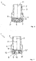
- Nachfolgend wird die Erfindung anhand eines in der Zeichnung dargestellten Ausführungsbeispiels näher erläutert. Weitere Merkmale der Erfindung können sich aus der folgenden Beschreibung des Ausführungsbeispiels der Erfindung in Verbindung mit den Ansprüchen und der beigefügten Zeichnung ergeben. Die einzelnen Merkmale der Erfindung können dabei für sich allein oder zu mehreren bei unterschiedlichen Ausführungsformen der Erfindung verwirklicht sein. Es stellen dar:
- Figur 1
- einen Haltetubus des Bearbeitungskopfes einer erfindungsgemäßen Laservorrichtung, für eine die Werkstücke pressende und den Laserstrahl fokussierende Zylinderlinse in einer Seitenansicht;
- Figur 2
- den Haltetubus aus
Figur 1 in einer Stirnansicht, mit Blick auf Zylinderlinse; - Figur 3
- den Haltetubus aus
Figur 1 in einer ersten Achsschnittdarstellung, senkrecht zur Mittelachse der Zylinderlinse; und - Figur 4
- den Haltetubus aus
Figur 1 in einer zweiten Achsschnittdarstellung quer zur Längsachse der Zylinderlinse. -
Figur 1 zeigt einen Haltetubus 1 eines in der Zeichnung nicht dargestellten Bearbeitungskopfes einer erfindungsgemäßen Laservorrichtung. Der Haltetubus 1 ist als abgestufter Hohlzylinder ausgebildet und mit einer Befestigungseinrichtung 2 an den Bearbeitungskopf lösbar befestigbar, nachdem dieser mit einem oberen Verbindungsabschnitt 3 in einen Hohlraum des Bearbeitungskopfes eingeführt ist. In dem Bearbeitungskopf sind außerdem Fokussierungseinrichtungen vorgesehen, die einen von einer Laserquelle ausgehenden eingekoppelten Laserstrahl formen und lenken. - An einem unteren Befestigungsabschnitt 4 des Haltetubus 1, der direkt mit einem vergrößerten Durchmesser an den Verbindungsabschnitt 3 anschließt, ist eine Zylinderlinse 5 über einen Aufnahmering 6 beweglich mit dem Haltetubus 1 verbunden. Der Haltetubus 1 und der Aufnahmering 6 sind aus Metall gefertigt. Die Zylinderlinse 5 ist für den in der Zeichnung nicht dargestellten Laserstrahl durchlässig und besteht aus Glas oder einem transparenten Kunststoffmaterial.
- Die
Figur 1 sowie dieFigur 2 zeigen die Zylinderlinse 5 in einer Schwenklage gegenüber dem Haltetubus 1. In einer in der Zeichnung nicht ausgeführten Normallage sind der Aufnahmering 6 und die Zylinderlinse 5 senkrecht zur Achse des Tubus 1 ausgerichtet. -
Figur 2 zeigt den Haltetubus 1 gemäßFigur 1 in einer Stirnansicht mit Blick auf die Zylinderlinse 5. Die Zylinderlinse 5 ist mit einem zweidimensionalen Freiheitsgrad in den Haltetubus 1 nach Art einer kardanischen Aufhängung befestigt. Der Aufnahmering 6 ist mit zwei ersten Drehachsen 7, 7', von denen die Drehachse 7 auch in derFigur 1 sichtbar ist, schwenkbar mit dem Haltetubus 1 verbunden. Um 90 Grad versetzt zu den ersten Drehachsen 7, 7' sind zwei zweite Drehachsen 8, 8' vorgesehen, die die Zylinderlinse 5 drehbar mit dem Aufnahmering 6 verbinden. - Die Drehachsen 8, 8' fluchten mit der axialen Mittelachse 9 der Zylinderlinse 5. Damit kann sich diese in Bewegungsrichtung des Bearbeitungskopfes drehen, wenn sie an die in der Zeichnung nicht dargestellten Werkstücke angepresst ist und der Bearbeitungskopf senkrecht zu der Mittelachse 9 der Zylinderlinse 5 voroder rückwärts bewegt wird.
- Wenn der Bearbeitungskopf mit dem Tubus 1 an irgendeiner Stelle der Schweißkontur nicht genau senkrecht gegenüber der Oberfläche der Werkstücke ausgerichtet ist, richtet sich der Aufnahmering 6, der die Zylinderlinse 5 trägt, automatisch durch die unsymmetrisch zu dem Zentrum 10 der Zylinderlinse 5 auf die Zylinderlinse 5 einwirkende Anpresskraft parallel und/oder tangential zu der Oberfläche der Werkstücke aus. Dabei schwenkt der Aufnahmering 6 um die Drehachsen 7, 7'.
-
Figur 3 zeigt den Haltetubus 1 in einer ersten Achsschnittdarstellung, bei der die Zylinderlinse 5 in Querrichtung senkrecht zu deren Mittelachse 9 geschnitten ist. Der Aufnahmering 6 ist wie auch bei den anderen Figuren der Zeichnung um einige Winkelgrade gegenüber dem Tubus 1 um die beiden Drehachsen 7, 7' gekippt. Die in Längsrichtung verlaufende Mittelachse 9 der Zylinderlinse 5 ist in Verlängerung der zentralen Längsachse 11 des Haltetubus 1 angeordnet, entlang der sich auch der in der Figur nicht dargestellte Laserstrahl erstreckt. Der Laserstrahl trifft die Zylinderlinse 5 damit immer, sowohl in der Normal-, wie auch in der Schwenklage, im Bereich der durch die Mittelachse 9 bestimmten Mittelebene. -
Figur 4 zeigt den Haltetubus 1 in einer gegenüber derFigur 3 um 90 Grad versetzten Achsschnittdarstellung. Die Drehachsen 8, 8' für die Zylinderlinse 5 sind in beidseitigen Gleitlagern 12, 12' aufgenommen, die in dem Aufnahmering 6 eingepresst sind. Das Zentrum 10 der Zylinderlinse 5 ist dabei in direkter Verlängerung der Längsachse 11 des Haltetubus 1 angeordnet, so dass der Laserstrahl unabhängig von der Neigung der Zylinderlinse 5 gegenüber dem Tubus 1 die Zylinderlinse 5 mittig passiert. Damit wird die räumliche Lage der Fokuslinie bezüglich der Werkstücke beim Kippen der Zylinderlinse 5 nur geringfügig beeinflusst.
Claims (4)
- Laservorrichtung zum Verbinden von Werkstücken aus Kunststoff in Durchstrahltechnik, mit einem Bearbeitungskopf, der Fokussierungseinrichtungen für den Laserstrahl aufweist, wobei die den Werkstücken nächstliegende Fokussierungseinrichtung eine als Rolle ausgebildete drehbar gelagerte Zylinderlinse (5) aufweist, die den Laserstrahl längs einer einzigen Achse fokussiert und die die Werkstücke in einem Bereich um die Auftreffstelle des Laserstrahls linienförmig zusammenpresst, durch gekennzeichnet, dass der Bearbeitungskopf eine Pendelaufhängung für die drehbare Zylinderlinse (5) aufweist.
- Laservorrichtung nach Anspruch 1, dadurch gekennzeichnet, dass die Kippachse der Pendelaufhängung durch das Zentrum (10) der Zylinderlinse (5) geht.
- Laservorrichtung nach Anspruch 1 oder 2, dadurch gekennzeichnet, dass die als Anpressrolle wirkende Zylinderlinse (5) über ein Kreuzgelenk mit dem Bearbeitungskopf verbunden ist.
- Laservorrichtung nach einem der vorangegangenen Ansprüche, dadurch gekennzeichnet, dass die Zylinderlinse (5) nur mit einer Stirnseite mit der Pendelaufhängung verbunden ist.
Applications Claiming Priority (1)
| Application Number | Priority Date | Filing Date | Title |
|---|---|---|---|
| DE202008006180U DE202008006180U1 (de) | 2008-05-06 | 2008-05-06 | Laservorrichtung mit pendelfähiger Anpressrolle |
Publications (3)
| Publication Number | Publication Date |
|---|---|
| EP2116355A2 EP2116355A2 (de) | 2009-11-11 |
| EP2116355A3 EP2116355A3 (de) | 2015-01-07 |
| EP2116355B1 true EP2116355B1 (de) | 2016-07-13 |
Family
ID=39744582
Family Applications (1)
| Application Number | Title | Priority Date | Filing Date |
|---|---|---|---|
| EP09003528.8A Active EP2116355B1 (de) | 2008-05-06 | 2009-03-11 | Laservorrichtung mit pendelfähiger Anpressrolle |
Country Status (4)
| Country | Link |
|---|---|
| US (1) | US8084709B2 (de) |
| EP (1) | EP2116355B1 (de) |
| CN (1) | CN101574849B (de) |
| DE (1) | DE202008006180U1 (de) |
Cited By (2)
| Publication number | Priority date | Publication date | Assignee | Title |
|---|---|---|---|---|
| US11819942B2 (en) | 2020-12-10 | 2023-11-21 | Magna International Inc. | Method and apparatus for applying an active joining force during laser welding of overlapping workpieces |
| US12172384B2 (en) | 2019-06-17 | 2024-12-24 | Magna International Inc. | Optical wheel assembly for a laser transmission welding apparatus |
Families Citing this family (4)
| Publication number | Priority date | Publication date | Assignee | Title |
|---|---|---|---|---|
| CN102672350A (zh) * | 2012-02-09 | 2012-09-19 | 王瑛玮 | 气流压合线形轨迹透射加工装置 |
| CN103935044B (zh) * | 2014-05-07 | 2017-01-11 | 王瑛玮 | 预浸料激光扫描制备复合材料 |
| DE102014212837B4 (de) | 2014-07-02 | 2023-08-17 | Robert Bosch Gmbh | Fügevorrichtung und Verfahren zum aneinander Fügen von toleranzbehafteten Werkstücken |
| DE102021126756A1 (de) | 2021-10-15 | 2023-04-20 | Trumpf Werkzeugmaschinen Gmbh + Co. Kg | Kollisionsschutz für einen Bearbeitungskopf einer Laserbearbeitungsmaschine |
Family Cites Families (8)
| Publication number | Priority date | Publication date | Assignee | Title |
|---|---|---|---|---|
| JPS5746831A (en) * | 1980-07-31 | 1982-03-17 | Mitsubishi Chem Ind Ltd | Surface treatment device of synthetic resin molded product |
| JPS58163587A (ja) * | 1982-03-23 | 1983-09-28 | Toshiba Corp | レ−ザ溶接用ノズル |
| SU1412987A1 (ru) * | 1986-09-15 | 1988-07-30 | Институт Электросварки Им.Е.О.Патона | Сварочное устройство дл изготовлени электропроводки |
| DE4319742A1 (de) * | 1993-06-15 | 1994-12-22 | Ghassem Dipl Ing Azdasht | Laserkugelschreiber |
| ES2249527T3 (es) * | 2002-10-02 | 2006-04-01 | Leister Process Technologies | Procedimiento y dispositivo para unir piezas de plastico de forma tridimensional por medio de un rayo laser. |
| JP2004142225A (ja) * | 2002-10-23 | 2004-05-20 | Terumo Corp | シート材の融着方法および成形品 |
| JP2005081396A (ja) * | 2003-09-09 | 2005-03-31 | Nissan Motor Co Ltd | レーザ溶着装置およびレーザ溶着方法 |
| CN102079135A (zh) * | 2010-12-24 | 2011-06-01 | 中国科学院长春光学精密机械与物理研究所 | 一种三维激光塑料焊接加工头 |
-
2008
- 2008-05-06 DE DE202008006180U patent/DE202008006180U1/de not_active Expired - Lifetime
-
2009
- 2009-03-11 EP EP09003528.8A patent/EP2116355B1/de active Active
- 2009-05-05 CN CN2009101391016A patent/CN101574849B/zh active Active
- 2009-05-05 US US12/435,476 patent/US8084709B2/en active Active
Cited By (2)
| Publication number | Priority date | Publication date | Assignee | Title |
|---|---|---|---|---|
| US12172384B2 (en) | 2019-06-17 | 2024-12-24 | Magna International Inc. | Optical wheel assembly for a laser transmission welding apparatus |
| US11819942B2 (en) | 2020-12-10 | 2023-11-21 | Magna International Inc. | Method and apparatus for applying an active joining force during laser welding of overlapping workpieces |
Also Published As
| Publication number | Publication date |
|---|---|
| US20090277886A1 (en) | 2009-11-12 |
| CN101574849A (zh) | 2009-11-11 |
| US8084709B2 (en) | 2011-12-27 |
| DE202008006180U1 (de) | 2008-09-11 |
| CN101574849B (zh) | 2013-08-14 |
| EP2116355A2 (de) | 2009-11-11 |
| EP2116355A3 (de) | 2015-01-07 |
Similar Documents
| Publication | Publication Date | Title |
|---|---|---|
| EP1525972B1 (de) | Verfahren und Vorrichtung zum Erwärmen von Kunststoffen mittels Laserstrahlen | |
| DE60209159T2 (de) | Verfahren und Vorrichtung zum Laserschweissen von zwei oder mehr überlappenden Blechen und zum Klemmen der Bleche | |
| EP0310793B1 (de) | Laserschweissgerät zum Schweissen von Hohlprofilen und Flachprofilen | |
| DE69527858T2 (de) | Optische Einrichtung zur Werkstoffbearbeitung mittels Laser | |
| EP1575756B1 (de) | Verfahren und vorrichtung zum verschweissen thermoplastischer kunststoff-formteile, insbesondere zum konturschweissen dreidimensionaler formteile | |
| DE102007038502B4 (de) | Verfahren zum Fügen von mindestens zwei Werkstücken mittels eines Laserstrahls | |
| EP1405713A1 (de) | Verfahren und Vorrichtung zum Verbinden von Werkstücken aus Kunststoff in dreidimensionaler Form mittels Laserstrahl | |
| EP2116355A2 (de) | Laservorrichtung mit pendelfähiger Anpressrolle | |
| EP2316606A2 (de) | Vorrichtung für das Durchstrahlschweißen von Bauteilen über eine ringförmige Kontaktzone | |
| DE202013102577U1 (de) | Bearbeitungseinrichtung | |
| DE10261422B4 (de) | Laserschweiß- und lötverfahren sowie Vorrichtung dazu | |
| DE112020001561T5 (de) | Optische radanordnung für ein laser-durchstrahlschweissgerät | |
| DE8900556U1 (de) | Vorrichtung zum Spannen und anschließenden Verbinden von Blechen mittels Laser-Naht-Schweißen im Karosseriebau | |
| DE102021131399A1 (de) | Verfahren und vorrichtung zum aufbringen einer aktiven verbindungskraft beim laserschweissen von sich überlappenden werkstücken | |
| EP1440784A1 (de) | Verfahren und Vorrichtung zum Verbinden von Werkstücken aus Kunststoff mittels Laserstrahl | |
| WO2016188564A1 (de) | Fügeverfahren und fügevorrichtung zum verbinden von wenigstens zwei bauteilen mittels eines hilfsfügeteiles und laserschweissens | |
| DE102011117454A1 (de) | Laserbearbeitungsvorrichtung | |
| DE102005018727A1 (de) | Verfahren und Vorrichtung zum Verschweißen von zwei Werkstücken aus thermoplastischen Kunststoffen mittels Laserstrahlung | |
| DE60018337T2 (de) | Laserschweissvorrichtung für metallische Bauteile und Kontaktstecker | |
| DE10131883B4 (de) | Verfahren zum Verschweißen von Metallbauteilen | |
| DE10304709B4 (de) | Verfahren und Vorrichtung zum Laser-Hybridschweißen | |
| DE202023106863U1 (de) | Vorrichtung und System zum Laserkunststoffschweißen | |
| DE4111876C2 (de) | Verfahren zum Fügen von Metallteilen mit einem Energiestrahl | |
| EP3181331A1 (de) | Verfahren und vorrichtung zum laserschweissen von dreidimensionalen kunststoffteilen | |
| DE10248955B3 (de) | Schweißvorrichtung für zwei oder mehrere Bleche |
Legal Events
| Date | Code | Title | Description |
|---|---|---|---|
| PUAI | Public reference made under article 153(3) epc to a published international application that has entered the european phase |
Free format text: ORIGINAL CODE: 0009012 |
|
| AK | Designated contracting states |
Kind code of ref document: A2 Designated state(s): AT BE BG CH CY CZ DE DK EE ES FI FR GB GR HR HU IE IS IT LI LT LU LV MC MK MT NL NO PL PT RO SE SI SK TR |
|
| AX | Request for extension of the european patent |
Extension state: AL BA RS |
|
| RAP1 | Party data changed (applicant data changed or rights of an application transferred) |
Owner name: LEISTER TECHNOLOGIES AG |
|
| TPAB | Information related to observations by third parties deleted |
Free format text: ORIGINAL CODE: EPIDOSDTIPA |
|
| TPAC | Observations filed by third parties |
Free format text: ORIGINAL CODE: EPIDOSNTIPA |
|
| PUAL | Search report despatched |
Free format text: ORIGINAL CODE: 0009013 |
|
| AK | Designated contracting states |
Kind code of ref document: A3 Designated state(s): AT BE BG CH CY CZ DE DK EE ES FI FR GB GR HR HU IE IS IT LI LT LU LV MC MK MT NL NO PL PT RO SE SI SK TR |
|
| AX | Request for extension of the european patent |
Extension state: AL BA RS |
|
| RIC1 | Information provided on ipc code assigned before grant |
Ipc: B23K 26/02 20140101ALI20141204BHEP Ipc: B29C 65/16 20060101AFI20141204BHEP |
|
| 17P | Request for examination filed |
Effective date: 20141219 |
|
| RBV | Designated contracting states (corrected) |
Designated state(s): AT BE BG CH CY CZ DE DK EE ES FI FR GB GR HR HU IE IS IT LI LT LU LV MC MK MT NL NO PL PT RO SE SI SK TR |
|
| RBV | Designated contracting states (corrected) |
Designated state(s): AT BE BG CH CY CZ DE DK EE ES FI FR GB GR HR HU IE IS IT LI LT LU LV MC MK MT NL NO PL PT RO SE SI SK TR |
|
| RBV | Designated contracting states (corrected) |
Designated state(s): AT BE BG CH CY CZ DE DK EE ES FI FR GB GR HR HU IE IS IT LI LT LU LV MC MK MT NL NO PL PT RO SE SI SK TR |
|
| AKX | Designation fees paid |
Designated state(s): AT BE BG CH CY CZ DE DK EE ES FI FR GB GR HR HU IE IS IT LI LT LU LV MC MK MT NL NO PL PT RO SE SI SK TR |
|
| AXX | Extension fees paid |
Extension state: BA Extension state: RS Extension state: AL |
|
| GRAP | Despatch of communication of intention to grant a patent |
Free format text: ORIGINAL CODE: EPIDOSNIGR1 |
|
| INTG | Intention to grant announced |
Effective date: 20160401 |
|
| GRAS | Grant fee paid |
Free format text: ORIGINAL CODE: EPIDOSNIGR3 |
|
| GRAA | (expected) grant |
Free format text: ORIGINAL CODE: 0009210 |
|
| AK | Designated contracting states |
Kind code of ref document: B1 Designated state(s): AT BE BG CH CY CZ DE DK EE ES FI FR GB GR HR HU IE IS IT LI LT LU LV MC MK MT NL NO PL PT RO SE SI SK TR |
|
| REG | Reference to a national code |
Ref country code: GB Ref legal event code: FG4D Free format text: NOT ENGLISH |
|
| REG | Reference to a national code |
Ref country code: AT Ref legal event code: REF Ref document number: 811930 Country of ref document: AT Kind code of ref document: T Effective date: 20160715 Ref country code: CH Ref legal event code: EP |
|
| REG | Reference to a national code |
Ref country code: IE Ref legal event code: FG4D Free format text: LANGUAGE OF EP DOCUMENT: GERMAN |
|
| REG | Reference to a national code |
Ref country code: DE Ref legal event code: R096 Ref document number: 502009012798 Country of ref document: DE |
|
| REG | Reference to a national code |
Ref country code: LT Ref legal event code: MG4D |
|
| REG | Reference to a national code |
Ref country code: NL Ref legal event code: MP Effective date: 20160713 |
|
| PG25 | Lapsed in a contracting state [announced via postgrant information from national office to epo] |
Ref country code: NO Free format text: LAPSE BECAUSE OF FAILURE TO SUBMIT A TRANSLATION OF THE DESCRIPTION OR TO PAY THE FEE WITHIN THE PRESCRIBED TIME-LIMIT Effective date: 20161013 Ref country code: FI Free format text: LAPSE BECAUSE OF FAILURE TO SUBMIT A TRANSLATION OF THE DESCRIPTION OR TO PAY THE FEE WITHIN THE PRESCRIBED TIME-LIMIT Effective date: 20160713 Ref country code: IS Free format text: LAPSE BECAUSE OF FAILURE TO SUBMIT A TRANSLATION OF THE DESCRIPTION OR TO PAY THE FEE WITHIN THE PRESCRIBED TIME-LIMIT Effective date: 20161113 Ref country code: LT Free format text: LAPSE BECAUSE OF FAILURE TO SUBMIT A TRANSLATION OF THE DESCRIPTION OR TO PAY THE FEE WITHIN THE PRESCRIBED TIME-LIMIT Effective date: 20160713 Ref country code: NL Free format text: LAPSE BECAUSE OF FAILURE TO SUBMIT A TRANSLATION OF THE DESCRIPTION OR TO PAY THE FEE WITHIN THE PRESCRIBED TIME-LIMIT Effective date: 20160713 Ref country code: HR Free format text: LAPSE BECAUSE OF FAILURE TO SUBMIT A TRANSLATION OF THE DESCRIPTION OR TO PAY THE FEE WITHIN THE PRESCRIBED TIME-LIMIT Effective date: 20160713 |
|
| PG25 | Lapsed in a contracting state [announced via postgrant information from national office to epo] |
Ref country code: ES Free format text: LAPSE BECAUSE OF FAILURE TO SUBMIT A TRANSLATION OF THE DESCRIPTION OR TO PAY THE FEE WITHIN THE PRESCRIBED TIME-LIMIT Effective date: 20160713 Ref country code: LV Free format text: LAPSE BECAUSE OF FAILURE TO SUBMIT A TRANSLATION OF THE DESCRIPTION OR TO PAY THE FEE WITHIN THE PRESCRIBED TIME-LIMIT Effective date: 20160713 Ref country code: SE Free format text: LAPSE BECAUSE OF FAILURE TO SUBMIT A TRANSLATION OF THE DESCRIPTION OR TO PAY THE FEE WITHIN THE PRESCRIBED TIME-LIMIT Effective date: 20160713 Ref country code: GR Free format text: LAPSE BECAUSE OF FAILURE TO SUBMIT A TRANSLATION OF THE DESCRIPTION OR TO PAY THE FEE WITHIN THE PRESCRIBED TIME-LIMIT Effective date: 20161014 Ref country code: PT Free format text: LAPSE BECAUSE OF FAILURE TO SUBMIT A TRANSLATION OF THE DESCRIPTION OR TO PAY THE FEE WITHIN THE PRESCRIBED TIME-LIMIT Effective date: 20161114 Ref country code: PL Free format text: LAPSE BECAUSE OF FAILURE TO SUBMIT A TRANSLATION OF THE DESCRIPTION OR TO PAY THE FEE WITHIN THE PRESCRIBED TIME-LIMIT Effective date: 20160713 |
|
| REG | Reference to a national code |
Ref country code: FR Ref legal event code: PLFP Year of fee payment: 9 |
|
| REG | Reference to a national code |
Ref country code: DE Ref legal event code: R097 Ref document number: 502009012798 Country of ref document: DE |
|
| PG25 | Lapsed in a contracting state [announced via postgrant information from national office to epo] |
Ref country code: RO Free format text: LAPSE BECAUSE OF FAILURE TO SUBMIT A TRANSLATION OF THE DESCRIPTION OR TO PAY THE FEE WITHIN THE PRESCRIBED TIME-LIMIT Effective date: 20160713 Ref country code: EE Free format text: LAPSE BECAUSE OF FAILURE TO SUBMIT A TRANSLATION OF THE DESCRIPTION OR TO PAY THE FEE WITHIN THE PRESCRIBED TIME-LIMIT Effective date: 20160713 |
|
| PLBE | No opposition filed within time limit |
Free format text: ORIGINAL CODE: 0009261 |
|
| STAA | Information on the status of an ep patent application or granted ep patent |
Free format text: STATUS: NO OPPOSITION FILED WITHIN TIME LIMIT |
|
| PG25 | Lapsed in a contracting state [announced via postgrant information from national office to epo] |
Ref country code: BG Free format text: LAPSE BECAUSE OF FAILURE TO SUBMIT A TRANSLATION OF THE DESCRIPTION OR TO PAY THE FEE WITHIN THE PRESCRIBED TIME-LIMIT Effective date: 20161013 Ref country code: SK Free format text: LAPSE BECAUSE OF FAILURE TO SUBMIT A TRANSLATION OF THE DESCRIPTION OR TO PAY THE FEE WITHIN THE PRESCRIBED TIME-LIMIT Effective date: 20160713 Ref country code: CZ Free format text: LAPSE BECAUSE OF FAILURE TO SUBMIT A TRANSLATION OF THE DESCRIPTION OR TO PAY THE FEE WITHIN THE PRESCRIBED TIME-LIMIT Effective date: 20160713 Ref country code: DK Free format text: LAPSE BECAUSE OF FAILURE TO SUBMIT A TRANSLATION OF THE DESCRIPTION OR TO PAY THE FEE WITHIN THE PRESCRIBED TIME-LIMIT Effective date: 20160713 |
|
| 26N | No opposition filed |
Effective date: 20170418 |
|
| PG25 | Lapsed in a contracting state [announced via postgrant information from national office to epo] |
Ref country code: SI Free format text: LAPSE BECAUSE OF FAILURE TO SUBMIT A TRANSLATION OF THE DESCRIPTION OR TO PAY THE FEE WITHIN THE PRESCRIBED TIME-LIMIT Effective date: 20160713 |
|
| REG | Reference to a national code |
Ref country code: CH Ref legal event code: PL |
|
| PG25 | Lapsed in a contracting state [announced via postgrant information from national office to epo] |
Ref country code: MC Free format text: LAPSE BECAUSE OF FAILURE TO SUBMIT A TRANSLATION OF THE DESCRIPTION OR TO PAY THE FEE WITHIN THE PRESCRIBED TIME-LIMIT Effective date: 20160713 |
|
| REG | Reference to a national code |
Ref country code: IE Ref legal event code: MM4A |
|
| PG25 | Lapsed in a contracting state [announced via postgrant information from national office to epo] |
Ref country code: LU Free format text: LAPSE BECAUSE OF NON-PAYMENT OF DUE FEES Effective date: 20170311 |
|
| PG25 | Lapsed in a contracting state [announced via postgrant information from national office to epo] |
Ref country code: LI Free format text: LAPSE BECAUSE OF NON-PAYMENT OF DUE FEES Effective date: 20170331 Ref country code: IE Free format text: LAPSE BECAUSE OF NON-PAYMENT OF DUE FEES Effective date: 20170311 Ref country code: CH Free format text: LAPSE BECAUSE OF NON-PAYMENT OF DUE FEES Effective date: 20170331 |
|
| REG | Reference to a national code |
Ref country code: BE Ref legal event code: MM Effective date: 20170331 |
|
| REG | Reference to a national code |
Ref country code: FR Ref legal event code: PLFP Year of fee payment: 10 |
|
| REG | Reference to a national code |
Ref country code: AT Ref legal event code: MM01 Ref document number: 811930 Country of ref document: AT Kind code of ref document: T Effective date: 20170311 |
|
| PG25 | Lapsed in a contracting state [announced via postgrant information from national office to epo] |
Ref country code: BE Free format text: LAPSE BECAUSE OF NON-PAYMENT OF DUE FEES Effective date: 20170331 |
|
| PG25 | Lapsed in a contracting state [announced via postgrant information from national office to epo] |
Ref country code: AT Free format text: LAPSE BECAUSE OF NON-PAYMENT OF DUE FEES Effective date: 20170311 |
|
| PG25 | Lapsed in a contracting state [announced via postgrant information from national office to epo] |
Ref country code: MT Free format text: LAPSE BECAUSE OF FAILURE TO SUBMIT A TRANSLATION OF THE DESCRIPTION OR TO PAY THE FEE WITHIN THE PRESCRIBED TIME-LIMIT Effective date: 20160713 |
|
| PG25 | Lapsed in a contracting state [announced via postgrant information from national office to epo] |
Ref country code: HU Free format text: LAPSE BECAUSE OF FAILURE TO SUBMIT A TRANSLATION OF THE DESCRIPTION OR TO PAY THE FEE WITHIN THE PRESCRIBED TIME-LIMIT; INVALID AB INITIO Effective date: 20090311 |
|
| PG25 | Lapsed in a contracting state [announced via postgrant information from national office to epo] |
Ref country code: CY Free format text: LAPSE BECAUSE OF NON-PAYMENT OF DUE FEES Effective date: 20160713 |
|
| PG25 | Lapsed in a contracting state [announced via postgrant information from national office to epo] |
Ref country code: MK Free format text: LAPSE BECAUSE OF FAILURE TO SUBMIT A TRANSLATION OF THE DESCRIPTION OR TO PAY THE FEE WITHIN THE PRESCRIBED TIME-LIMIT Effective date: 20160713 |
|
| PG25 | Lapsed in a contracting state [announced via postgrant information from national office to epo] |
Ref country code: TR Free format text: LAPSE BECAUSE OF FAILURE TO SUBMIT A TRANSLATION OF THE DESCRIPTION OR TO PAY THE FEE WITHIN THE PRESCRIBED TIME-LIMIT Effective date: 20160713 |
|
| REG | Reference to a national code |
Ref country code: DE Ref legal event code: R082 Ref document number: 502009012798 Country of ref document: DE Representative=s name: WITTE, WELLER & PARTNER PATENTANWAELTE MBB, DE |
|
| P01 | Opt-out of the competence of the unified patent court (upc) registered |
Effective date: 20230502 |
|
| REG | Reference to a national code |
Ref country code: DE Ref legal event code: R081 Ref document number: 502009012798 Country of ref document: DE Owner name: HYMSON SWITZERLAND AG, CH Free format text: FORMER OWNER: LEISTER TECHNOLOGIES AG, KAEGISWIL, CH |
|
| REG | Reference to a national code |
Ref country code: GB Ref legal event code: 732E Free format text: REGISTERED BETWEEN 20251120 AND 20251126 |
|
| PGFP | Annual fee paid to national office [announced via postgrant information from national office to epo] |
Ref country code: GB Payment date: 20260324 Year of fee payment: 18 |
|
| PGFP | Annual fee paid to national office [announced via postgrant information from national office to epo] |
Ref country code: DE Payment date: 20260324 Year of fee payment: 18 |
|
| PGFP | Annual fee paid to national office [announced via postgrant information from national office to epo] |
Ref country code: IT Payment date: 20260324 Year of fee payment: 18 |
|
| PGFP | Annual fee paid to national office [announced via postgrant information from national office to epo] |
Ref country code: FR Payment date: 20260320 Year of fee payment: 18 |