EP2116352A1 - Extrusions-Werkzeug für eine Vorrichtung zur Herstellung von Kunststoff-Verbundrohren mit Querrillen - Google Patents
Extrusions-Werkzeug für eine Vorrichtung zur Herstellung von Kunststoff-Verbundrohren mit Querrillen Download PDFInfo
- Publication number
- EP2116352A1 EP2116352A1 EP08008726A EP08008726A EP2116352A1 EP 2116352 A1 EP2116352 A1 EP 2116352A1 EP 08008726 A EP08008726 A EP 08008726A EP 08008726 A EP08008726 A EP 08008726A EP 2116352 A1 EP2116352 A1 EP 2116352A1
- Authority
- EP
- European Patent Office
- Prior art keywords
- channel
- distributor
- channels
- melt
- extrusion tool
- Prior art date
- Legal status (The legal status is an assumption and is not a legal conclusion. Google has not performed a legal analysis and makes no representation as to the accuracy of the status listed.)
- Granted
Links
Images


Classifications
-
- B—PERFORMING OPERATIONS; TRANSPORTING
- B29—WORKING OF PLASTICS; WORKING OF SUBSTANCES IN A PLASTIC STATE IN GENERAL
- B29C—SHAPING OR JOINING OF PLASTICS; SHAPING OF MATERIAL IN A PLASTIC STATE, NOT OTHERWISE PROVIDED FOR; AFTER-TREATMENT OF THE SHAPED PRODUCTS, e.g. REPAIRING
- B29C48/00—Extrusion moulding, i.e. expressing the moulding material through a die or nozzle which imparts the desired form; Apparatus therefor
- B29C48/25—Component parts, details or accessories; Auxiliary operations
- B29C48/36—Means for plasticising or homogenising the moulding material or forcing it through the nozzle or die
- B29C48/50—Details of extruders
- B29C48/695—Flow dividers, e.g. breaker plates
- B29C48/70—Flow dividers, e.g. breaker plates comprising means for dividing, distributing and recombining melt flows
- B29C48/705—Flow dividers, e.g. breaker plates comprising means for dividing, distributing and recombining melt flows in the die zone, e.g. to create flow homogeneity
-
- B—PERFORMING OPERATIONS; TRANSPORTING
- B29—WORKING OF PLASTICS; WORKING OF SUBSTANCES IN A PLASTIC STATE IN GENERAL
- B29C—SHAPING OR JOINING OF PLASTICS; SHAPING OF MATERIAL IN A PLASTIC STATE, NOT OTHERWISE PROVIDED FOR; AFTER-TREATMENT OF THE SHAPED PRODUCTS, e.g. REPAIRING
- B29C48/00—Extrusion moulding, i.e. expressing the moulding material through a die or nozzle which imparts the desired form; Apparatus therefor
- B29C48/03—Extrusion moulding, i.e. expressing the moulding material through a die or nozzle which imparts the desired form; Apparatus therefor characterised by the shape of the extruded material at extrusion
- B29C48/09—Articles with cross-sections having partially or fully enclosed cavities, e.g. pipes or channels
-
- B—PERFORMING OPERATIONS; TRANSPORTING
- B29—WORKING OF PLASTICS; WORKING OF SUBSTANCES IN A PLASTIC STATE IN GENERAL
- B29C—SHAPING OR JOINING OF PLASTICS; SHAPING OF MATERIAL IN A PLASTIC STATE, NOT OTHERWISE PROVIDED FOR; AFTER-TREATMENT OF THE SHAPED PRODUCTS, e.g. REPAIRING
- B29C48/00—Extrusion moulding, i.e. expressing the moulding material through a die or nozzle which imparts the desired form; Apparatus therefor
- B29C48/03—Extrusion moulding, i.e. expressing the moulding material through a die or nozzle which imparts the desired form; Apparatus therefor characterised by the shape of the extruded material at extrusion
- B29C48/12—Articles with an irregular circumference when viewed in cross-section, e.g. window profiles
-
- B—PERFORMING OPERATIONS; TRANSPORTING
- B29—WORKING OF PLASTICS; WORKING OF SUBSTANCES IN A PLASTIC STATE IN GENERAL
- B29C—SHAPING OR JOINING OF PLASTICS; SHAPING OF MATERIAL IN A PLASTIC STATE, NOT OTHERWISE PROVIDED FOR; AFTER-TREATMENT OF THE SHAPED PRODUCTS, e.g. REPAIRING
- B29C48/00—Extrusion moulding, i.e. expressing the moulding material through a die or nozzle which imparts the desired form; Apparatus therefor
- B29C48/16—Articles comprising two or more components, e.g. co-extruded layers
- B29C48/18—Articles comprising two or more components, e.g. co-extruded layers the components being layers
- B29C48/21—Articles comprising two or more components, e.g. co-extruded layers the components being layers the layers being joined at their surfaces
-
- B—PERFORMING OPERATIONS; TRANSPORTING
- B29—WORKING OF PLASTICS; WORKING OF SUBSTANCES IN A PLASTIC STATE IN GENERAL
- B29C—SHAPING OR JOINING OF PLASTICS; SHAPING OF MATERIAL IN A PLASTIC STATE, NOT OTHERWISE PROVIDED FOR; AFTER-TREATMENT OF THE SHAPED PRODUCTS, e.g. REPAIRING
- B29C48/00—Extrusion moulding, i.e. expressing the moulding material through a die or nozzle which imparts the desired form; Apparatus therefor
- B29C48/25—Component parts, details or accessories; Auxiliary operations
- B29C48/255—Flow control means, e.g. valves
- B29C48/2556—Flow control means, e.g. valves provided in or in the proximity of dies
-
- B—PERFORMING OPERATIONS; TRANSPORTING
- B29—WORKING OF PLASTICS; WORKING OF SUBSTANCES IN A PLASTIC STATE IN GENERAL
- B29C—SHAPING OR JOINING OF PLASTICS; SHAPING OF MATERIAL IN A PLASTIC STATE, NOT OTHERWISE PROVIDED FOR; AFTER-TREATMENT OF THE SHAPED PRODUCTS, e.g. REPAIRING
- B29C48/00—Extrusion moulding, i.e. expressing the moulding material through a die or nozzle which imparts the desired form; Apparatus therefor
- B29C48/25—Component parts, details or accessories; Auxiliary operations
- B29C48/30—Extrusion nozzles or dies
- B29C48/303—Extrusion nozzles or dies using dies or die parts movable in a closed circuit, e.g. mounted on movable endless support
-
- B—PERFORMING OPERATIONS; TRANSPORTING
- B29—WORKING OF PLASTICS; WORKING OF SUBSTANCES IN A PLASTIC STATE IN GENERAL
- B29C—SHAPING OR JOINING OF PLASTICS; SHAPING OF MATERIAL IN A PLASTIC STATE, NOT OTHERWISE PROVIDED FOR; AFTER-TREATMENT OF THE SHAPED PRODUCTS, e.g. REPAIRING
- B29C48/00—Extrusion moulding, i.e. expressing the moulding material through a die or nozzle which imparts the desired form; Apparatus therefor
- B29C48/25—Component parts, details or accessories; Auxiliary operations
- B29C48/30—Extrusion nozzles or dies
- B29C48/32—Extrusion nozzles or dies with annular openings, e.g. for forming tubular articles
- B29C48/335—Multiple annular extrusion nozzles in coaxial arrangement, e.g. for making multi-layered tubular articles
- B29C48/336—Multiple annular extrusion nozzles in coaxial arrangement, e.g. for making multi-layered tubular articles the components merging one by one down streams in the die
- B29C48/3366—Multiple annular extrusion nozzles in coaxial arrangement, e.g. for making multi-layered tubular articles the components merging one by one down streams in the die using a die with concentric parts, e.g. rings, cylinders
-
- B—PERFORMING OPERATIONS; TRANSPORTING
- B29—WORKING OF PLASTICS; WORKING OF SUBSTANCES IN A PLASTIC STATE IN GENERAL
- B29C—SHAPING OR JOINING OF PLASTICS; SHAPING OF MATERIAL IN A PLASTIC STATE, NOT OTHERWISE PROVIDED FOR; AFTER-TREATMENT OF THE SHAPED PRODUCTS, e.g. REPAIRING
- B29C48/00—Extrusion moulding, i.e. expressing the moulding material through a die or nozzle which imparts the desired form; Apparatus therefor
- B29C48/03—Extrusion moulding, i.e. expressing the moulding material through a die or nozzle which imparts the desired form; Apparatus therefor characterised by the shape of the extruded material at extrusion
- B29C48/06—Rod-shaped
-
- B—PERFORMING OPERATIONS; TRANSPORTING
- B29—WORKING OF PLASTICS; WORKING OF SUBSTANCES IN A PLASTIC STATE IN GENERAL
- B29C—SHAPING OR JOINING OF PLASTICS; SHAPING OF MATERIAL IN A PLASTIC STATE, NOT OTHERWISE PROVIDED FOR; AFTER-TREATMENT OF THE SHAPED PRODUCTS, e.g. REPAIRING
- B29C48/00—Extrusion moulding, i.e. expressing the moulding material through a die or nozzle which imparts the desired form; Apparatus therefor
- B29C48/03—Extrusion moulding, i.e. expressing the moulding material through a die or nozzle which imparts the desired form; Apparatus therefor characterised by the shape of the extruded material at extrusion
- B29C48/13—Articles with a cross-section varying in the longitudinal direction, e.g. corrugated pipes
Definitions
- the invention relates to an extrusion tool according to the preamble of claim 1.
- Extrusion tools which are also referred to in practice as tube heads, the general genus, as for example from the EP 0 834 386 B1 (Corr. U.S. Patent 6,045,347 ) are known, become larger and heavier with increasing diameter of the composite pipes to be produced. Their production is therefore increasingly too expensive.
- the invention is therefore based on the object, an extrusion tool of the generic type in such a way that the risk of leakage is excluded.
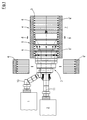
- Fig. 1 can recognize, has an apparatus for producing plastic composite pipes with transverse grooves on two extruders 1, 2, which are connected to an extrusion die 3, which is also referred to in practice as a pipe head. From the extrusion die 3, two plastic melt tubes are coextruded, from which the mentioned composite tube is formed. This purpose is served by a forming machine 4, also referred to as a corrugator, which is formed from half-molds 6, 6 'provided with an internal profiling 5, which are placed in pairs on a forming path 7 and in a direction of movement 8 of the latter Form formed form 9 are close to each other. In the mold 9, the aforementioned composite pipes are formed. This technique is well known in the art and for example in the EP 0 764 516 B1 (Corr. U.S. Patent 5,693,347 ) is shown and described, which may be referred to for explanation.
- the extruder 1 is a so-called side extruder because it opens via a lateral melt line 10 in the extrusion die 3, while the other extruder 2 in the center, d. H. concentric with the central longitudinal axis 11 of the mold 9 opens into the extrusion die 3.
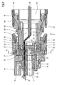
- the extrusion tool 3 has a screwed together of several parts inner nozzle mandrel 12, which is penetrated by a coaxial with the axis 11 extending conduit channel 65.
- the inner nozzle mandrel 12 is surrounded concentrically to the axis 11 by a likewise multi-part inner nozzle shell 13, which in turn is likewise surrounded concentrically to the axis 11 by an outer nozzle mandrel 14.
- an outer channel 17 is limited.
- the inner channel 16 opens out of the extrusion tool 3 by means of an inner nozzle 18, while the outer channel 17 opens out of the extrusion tool 3 by means of an outer nozzle 19.
- From the two nozzles 18, 19 of the aforementioned inner tube or the aforementioned outer tube are extruded, which in example from the EP 0 563 575 (Corr. US 5,320,797 ) known manner to a composite pipe are connected together.
- the inner nozzle mandrel 12, the inner nozzle casing 13, the outer nozzle mandrel 14 and the outer nozzle casing 15 are attached to a support member 23 with the interposition of an inner star distributor 20 and an outer star distributor 21 and a quill tool 22 , In the area of this support member 23, the extrusion tool 3 is supported via a support structure, not shown, on a foundation, also not shown, as is customary in practice.
- the melt line 10 from the side extruder 1 opens into the quill tool 22, which has a dust bar or a flow resistance 24, by means of which it is ensured that the supplied from the extruder 1 plastic melt distributed evenly over the circumference of a ring Channel 25 is supplied, from where it enters the outer star distributor 21.
- the extruder 2 opens into the inner star distributor 20 via a melt channel 26 which is concentric with the axis 11 and also passes through the sleeve tool 22 and the outer star distributor 21, as a whole Fig. 2 is removable.
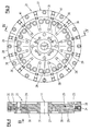
- the outer-star distributor 21 essentially consists of a solid annular cylindrical steel disk 27, in which from the annular cylindrical outer peripheral surface 28 forth radially to the central longitudinal axis 11 radial channels 29 at equal angular intervals to each other are bored. At the radially inner end of these radial channels 29 open into this parallel to the axis 11 extending connection channels 30, which are drilled by the annular channel 25 facing end face 31 of the disc 27 in this, wherein the radial distance of these connection channels 30 of the axis 11 to the radius of the ring channel 25 - also with respect to the axis 11 - corresponds, so that the connection channels 30 and thus also the radial channels 29 are connected to the ring channel 25.
- a series of line passages 38 are provided, are passed through the supply lines 39 and passed through the line channel 65 to a flanged to the extrusion die 3 cooling and calibration mandrel 40.
- the supply lines 39 are arranged between the melt channels 25, 26, in a symmetrical arrangement around the circumference.
- four line passages 38 are provided at angular intervals of 90 °.
- through-holes 41 are provided for ventilation lines 56. These are arranged symmetrically over the circumference, as the Fig. 3 and 5 is removable.
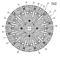
- the indoor star distributor 20 is - like the 6 and 7 can be removed - also from an approximately annular cylindrical steel disk 42, in which are also drilled from the outer circumferential surface 43 of radial channels 44, which on the outer star distributor 21 facing end face 45 in a concentric with the axis 11 screwed frusto-conical deflection surface 46 open, which forms the end face of the melt channel 26.
- the radial channels 44 open via parallel to the axis 11 extending exit channels 47 on the end face 45 facing away from end face 48 of the inner star distributor 20 and open into the inner channel 16.
- the radial channels 44 are closed by means of screw plugs 49, so that the radial channels 44 with the outlet channels 47 in self-contained, exclusively in the disc 42 extending inner distributor channels 50 form.
- through holes 51 are formed in the disk 42 of the inner star distributor 20, through which screws 52 for connecting the inner star distributor 20 to the inner nozzle arbor 12 are guided.
- radial holes 53 are formed, which open at the outer peripheral surface 43 in the disc 42 in a multi-part outer nozzle mandrel 14 formed ventilation and venting channel 54 which between the outer nozzle 19 and the inner nozzle 18 from the extrusion die 3 opens.
- These radial bores 53 are guided through connection bores 55 to the end face 45 of the inner star distributor 20, where they are connected to the passage bores 41 on the outer star distributor 21. Over this, the ventilation channel 54 can be connected to the Beund vent lines 56.
- the star distributors 20, 21 are each connected by means of the described screw connections to the adjoining parts, namely the outer nozzle mandrel 14, the outer nozzle shell 15, the inner nozzle mandrel 12 and the inner nozzle shell 13, so that made an absolutely melt-tight connection is. Furthermore, the star distributors 20, 21 are also flat, ie seamless, close together. Within the star distributors 20, 21 are closed, so no joints having distributor channels 35 and 50 formed, where no melt could escape.
- the inner channel 16 and the outer channel 17 are in each case connected to the inner star distributor 20 and the outer star distributor 21 as helical screw channels 57 and 58 tapering in the direction of movement 8 (so-called helical channels).
- Distributor formed by the uniform distribution of the emerging from the inner-manifold channels 50 and outer-distribution channels 35 plastic melt over the entire circumference of the inner channel 16 and the outer channel 17 takes place.
- an outer nozzle ring 59 is arranged, which can be radially adjusted by means of adjusting screws 60, whereby the free cross section of the outer channel 17 are changed over its circumference can, that the passage of the plastic melt over the circumference of the outer channel 17 is as uniform as possible.
- a corresponding inner nozzle ring 61 with likewise radially acting adjusting screws 62 is provided in the inner channel 16 in front of the inner nozzle 18.
- deformable adjustment sleeves 63 are firmly integrated into the outer nozzle shell 15 and the inner nozzle shell 13, so that they form at this point a joint-free boundary of the outer channel 17 and the inner channel 16.
- deformation sleeves 63 can - like the 8 and 9 can be removed - are deformed by means of adjusting screws 60 and 62 radially to the axis 11, so that thereby the channel cross section of the outer channel 17 and the inner channel 16 is changed over the circumference.
- the extrusion tool 3 is equipped on all sides with heating elements 64, so that additional auxiliary body for heating the extrusion die 3 can be omitted.
Landscapes
- Engineering & Computer Science (AREA)
- Mechanical Engineering (AREA)
- Manufacturing & Machinery (AREA)
- Extrusion Moulding Of Plastics Or The Like (AREA)
Abstract
Description
- Die Erfindung betrifft ein Extrusions-Werkzeug nach dem Oberbegriff des Anspruches 1.
- Extrusions-Werkzeuge, die in der Praxis auch als Rohrköpfe bezeichnet werden, der allgemeinen Gattung, wie sie beispielsweise aus der
EP 0 834 386 B1 (entspr.US-PS 6,045,347 ) bekannt sind, werden mit zunehmendem Durchmesser der zu fertigenden Verbundrohre immer größer und schwerer. Ihre Herstellung wird daher auch zunehmend zu teuer. - Aus der
DE 10 2004 002 433 A1 (entspr.CA 2,416,083 /2,419,703 A ) ist es zur Lösung dieses Problems bekannt, zwei voneinander beabstandete Schmelze-Kanäle vorzusehen, die in ein Paket von Verteilerplatten einmünden. In deren Oberfläche sind Verteiler-Kanäle eingefräst, die die Kunststoff-Schmelze zum Innen-Kanal bzw. zum Außen-Kanal führen. Die Platten sind aneinander geschraubt. Aufgrund der außerordentlich großen Drücke und damit Kräfte, die von der Schmelze auf die Platten ausgeübt werden, besteht die Gefahr, dass die Platten aufgebogen werden und Undichtigkeiten auftreten, d. h. die Kunststoff-Schmelze tritt aus. Der Reinigungsaufwand hierfür ist erheblich. Außerdem ist eine gleichmäßige Verteilung des Kunststoffs nicht zu erreichen. - Im Prinzip ähnliche Extrusions-Werkzeuge sind aus der
EP 1 102 674 B1 (entspr.US-PS 6,616,437 ) und derEP 1 360 061 B1 (entspr.US-PS 7,037,098 ) bekannt. - Diese plattenförmigen Verteiler lassen sich an sich relativ einfach fertigen. Nachteilig ist die bereits erwähnte Gefahr einer Leckage aufgrund unterschiedlicher Biegewiderstandsmomente in Abhängigkeit vom Durchmesser der Platten. Damit ist eine sichere Abdichtung der Schmelzekanäle nicht einfach zu gewährleisten. Eine Zentrierung des Innen-Kanals und des Außen-Kanals ist bei diesen bekannten Extrusions-Werkzeugen nicht möglich.
- Der Erfindung liegt daher die Aufgabe zugrunde, ein Extrusions-Werkzeug der gattungsgemäßen Art so auszugestalten, dass die Gefahr von Leckagen ausgeschlossen ist.
- Diese Aufgabe wird erfindungsgemäß bei dem gattungsgemäßen Extrusions-Werkzeug mit den Merkmalen des Kennzeichnungsteils des Anspruches 1 gelöst. Da die Verteiler-Kanäle als geschlossene Kanäle innerhalb einteiliger bzw. einstückiger Platten bzw. Scheiben ausgebildet sind, treten keinerlei Abdichtungsprobleme auf. Da die Gesamtverteilung der Kunststoff-Schmelze innerhalb der Sternverteiler erfolgt, können in den nachfolgenden Kanälen, nämlich dem Innen-Kanal und dem Außen-Kanal, die zur Innen-Düse bzw. zur Außen-Düse führen, alle Einstellmöglichkeiten vorgesehen werden, wie sie zum Stand der Technik gehören, nämlich eine Zentrierung des Düsen-Spalts und eine Einstellung des Fließ-Querschnitts des jeweiligen Kanals über den Umfang, um eine gleichmäßige Wanddickenverteilung der zu extrudierenden Schläuche und damit der herzustellenden Rohre zu erreichen.
- Vorteilhafte Ausgestaltungen ergeben sich aus den Unteransprüchen.
- Weitere Merkmale, Vorteile und Einzelheiten der Erfindung ergeben sich aus der nachfolgenden Beschreibung eines Ausführungsbeispiels anhand der Zeichnung. Es zeigt:
- Fig. 1
- eine Draufsicht auf eine Vorrichtung zur Herstellung von Verbundrohren mit einem erfindungsgemäßen Extrusions- Werkzeug in schematischer Teil-Darstellung,
- Fig. 2
- einen Längsschnitt durch ein Extrusions-Werkzeug gemäß der Erfindung,
- Fig. 3
- eine Draufsicht auf einen Außen-Sternverteiler gemäß dem Sichtpfeil III in
Fig. 4 , - Fig. 4
- einen Querschnitt durch den Außen-Sternverteiler gemäß der Schnittlinie IV-IV in
Fig. 3 , - Fig. 5
- einen Schnitt durch den Außen-Sternverteiler gemäß der Schnittlinie V-V in
Fig. 2 , - Fig. 6
- eine Draufsicht auf einen Innen-Sternverteiler gemäß dem Sichtpfeil VI in
Fig. 7 , - Fig. 7
- einen Querschnitt durch den Innen-Sternverteiler gemäß der Schnittlinie VII-VII in
Fig. 6 , und - Fig. 8 und 9
- eine Einrichtung zur Veränderung des Querschnitts von In- nen-Kanal bzw. Außen-Kanal.
- Wie
Fig. 1 erkennen lässt, weist eine Vorrichtung zur Herstellung von Kunststoff-Verbundrohren mit Querrillen zwei Extruder 1, 2 auf, die an ein Extrusions-Werkzeug 3, das in der Praxis auch als Rohrkopf bezeichnet wird, angeschlossen sind. Aus dem Extrusions-Werkzeug 3 werden zwei Schläuche aus Kunststoffschmelze ineinander koextrudiert, aus denen das erwähnte Verbundrohr geformt wird. Hierzu dient eine in der Praxis auch als Korrugator bezeichnete Form-Maschine 4, die aus mit einer InnenProfilierung 5 versehenen Halb-Kokillen 6, 6' gebildet werden, die auf einer Formstrecke 7 paarweise aneinander gesetzt und in einer Bewegungs-Richtung 8 der auf diese Weise gebildeten Form 9 dicht aneinander liegen. In der Form 9 werden die erwähnten Verbundrohre geformt. Diese Technik ist in der Praxis allgemein bekannt und beispielsweise in derEP 0 764 516 B1 (entspr.US-PS 5,693,347 ) dargestellt und beschrieben ist, worauf zur Erläuterung verwiesen werden darf. - Der Extruder 1 ist ein sogenannter Seiten-Extruder, weil er über eine seitliche Schmelze-Leitung 10 in das Extrusions-Werkzeug 3 einmündet, während der andere Extruder 2 mittig, d. h. konzentrisch zur Mittel-Längs-Achse 11 der Form 9 in das Extrusions-Werkzeug 3 einmündet.
- Das Extrusions-Werkzeug 3 weist einen aus mehreren Teilen zusammengeschraubten Innen-Düsendorn 12 auf, der von einem koaxial zur Achse 11 verlaufenden Leitungs-Kanal 65 durchsetzt ist. Der Innen-Düsendorn 12 ist konzentrisch zur Achse 11 von einem ebenfalls mehrteiligen Innen-Düsenmantel 13 umgeben, der wiederum ebenfalls konzentrisch zur Achse 11 von einem Außen-Düsendorn 14 umgeben ist. Zwischen dem Innen-Düsendorn 12 und dem Innen-Düsenmantel 13 ist ein konzentrisch zur Achse 11 ausgebildeter Innen-Kanal 16 begrenzt, während zwischen dem Außen-Düsendorn 14 und einem Außen-Düsenmantel 15 ein Außen-Kanal 17 begrenzt ist. Der Innen-Kanal 16 mündet mittels einer Innen-Düse 18 aus dem Extrusions-Werkzeug 3 aus, während der Außen-Kanal 17 mittels einer Außen-Düse 19 aus dem Extrusions-Werkzeug 3 ausmündet. Aus den beiden Düsen 18, 19 werden der erwähnte Innen-Schlauch bzw. der erwähnte Außen-Schlauch extrudiert, die in beispielsweise aus der
EP 0 563 575 (entspr.US 5,320,797 ) bekannten Weise zu einem Verbundrohr miteinander verbunden werden. Der Innen-Düsendorn 12, der Innen-Düsenmantel 13, der Außen-Düsendorn 14 und der Außen-Düsenmantel 15 sind unter Zwischenschaltung eines Innen-Sternverteilers 20 und eines Außen-Sternverteilers 21 und eines Pinolen-Werkzeugs 22 an einem Trag-Teil 23 befestigt. Im Bereich dieses Trag-Teils 23 wird das Extrusions-Werkzeug 3 über eine nicht dargestellte Tragkonstruktion auf einem ebenfalls nicht dargestellten Fundament abgestützt, wie es in der Praxis üblich ist. - Die Schmelze-Leitung 10 vom Seiten-Extruder 1 mündet in das Pinolen-Werkzeug 22 ein, das einen Staubalken bzw. einen Strömungswiderstand 24 aufweist, mittels dessen sichergestellt wird, dass die vom Extruder 1 zugeführte Kunststoff-Schmelze über den Umfang gleichmäßig verteilt einem Ring-Kanal 25 zugeführt wird, von wo aus sie in den Außen-Sternverteiler 21 eintritt. Der Extruder 2 mündet über einen zur Achse 11 konzentrischen Schmelze-Kanal 26, der auch das Pinolen-Werkzeug 22 und den Außen-Sternverteiler 21 durchsetzt, in den Innen-Sternverteiler 20 ein, wie insgesamt
Fig. 2 entnehmbar ist. - Wie sich aus den
Fig. 3 bis 5 ergibt, besteht der Außen-Sternverteiler 21 im Wesentlichen aus einer massiven ringzylindrischen Stahl-Scheibe 27, in die von der ringzylindrischen Außen-Umfangs-Fläche 28 her radial zur Mittel-Längs-Achse 11 Radial-Kanäle 29 in gleichen Winkelabständen zueinander gebohrt sind. Am radial inneren Ende dieser Radial-Kanäle 29 münden in diese parallel zur Achse 11 verlaufende Anschluss-Kanäle 30 ein, die von der dem Ring-Kanal 25 zugewandten Stirnfläche 31 der Scheibe 27 in diese gebohrt sind, wobei der radiale Abstand dieser Anschluss-Kanäle 30 von der Achse 11 dem Radius des Ring-Kanals 25 - ebenfalls bezogen auf die Achse 11 - entspricht, so dass die Anschluss-Kanäle 30 und damit auch die Radial-Kanäle 29 an den Ring-Kanal 25 angeschlossen sind. Von der der Stirnfläche 31 abgewandten, dem Innen-Sternverteiler 20 zugewandten Stirnfläche 32 aus sind Austritts-Kanäle 33 in die Scheibe 27 gebohrt, die in die Radial-Kanäle 29 einmünden und über die die Radial-Kanäle 29 mit dem Außen-Kanal 17 verbunden sind. Radial außerhalb der Austritts-Kanäle 33 sind die Radial-Kanäle 29 nach außen mittels Schraub-Stopfen 34 verschlossen. Die Anschluss-Kanäle 30 mit den Radial-Kanälen 29 und den Austritts-Kanälen 33 bilden also Außen-Verteiler-Kanäle 35 zwischen Ring-Kanal 25 und Außen-Kanal 17. In der Scheibe 27 sind weiterhin zahlreiche Durchgangs-Bohrungen 36 für Verbindungs-Schrauben 37, mittels derer ein Teil des Außen-Düsendorns 14 mit dem Außen-Sternverteiler 21 axial verbunden ist. Des Weiteren sind eine Reihe von Leitungs-Durchlässen 38 vorgesehen, durch die Versorgungs-Leitungen 39 hindurchgeführt und durch den Leitungs-Kanal 65 zu einem an das Extrusions-Werkzeug 3 angeflanschten Kühl- und Kalibrier-Dorn 40 geführt werden. Wie denFig. 2 ,3 und5 entnehmbar ist, sind die Versorgungsleitungen 39 zwischen den Schmelze-Kanälen 25, 26 angeordnet, und zwar in symmetrischer Anordnung über den Umfang. Im dargestellten Ausführungsbeispiel sind vier Leitungs-Durchlässe 38 in Winkelabständen von 90° vorgesehen. Weiterhin sind Durchgangs-Bohrungen 41 für Be- und Entlüftungs-Leitungen 56 vorgesehen. Auch diese sind symmetrisch über den Umfang angeordnet, wie denFig. 3 und5 entnehmbar ist. - Der Innen-Sternverteiler 20 besteht - wie den
Fig. 6 und 7 entnehmbar ist - ebenfalls aus einer etwa ringzylindrischen Stahl-Scheibe 42, in die ebenfalls von der Außen-Umfangs-Fläche 43 aus Radial-Kanäle 44 gebohrt sind, die auf der dem Außen-Sternverteiler 21 zugewandten Stirnfläche 45 in eine konzentrisch zur Achse 11 eingedrehte kegelstumpfförmige Umlenk-Fläche 46 einmünden, die den stirnseitigen Abschluss des Schmelze-Kanals 26 bildet. Wie bei dem Außen-Sternverteiler 21 münden die Radial-Kanäle 44 über parallel zur Achse 11 verlaufende Austritts-Kanäle 47 auf der der Stirnfläche 45 abgewandten Stirnfläche 48 aus dem Innen-Sternverteiler 20 aus und münden in den Innen-Kanal 16. Radial außerhalb der Austritts-Kanäle 47 sind die Radial-Kanäle 44 mittels Schraub-Stopfen 49 verschlossen, so dass die Radial-Kanäle 44 mit den Austritts-Kanälen 47 in sich geschlossene, ausschließlich in der Scheibe 42 verlaufende Innen-Verteiler-Kanäle 50 bilden. Außerdem sind in der Scheibe 42 des Innen-Sternverteilers 20 Durchgangsbohrungen 51 ausgebildet, durch die hindurch Schrauben 52 zur Verbindung des Innen-Sternverteilers 20 mit dem Innen-Düsendorn 12 geführt sind. Darüber hinaus sind im Innen-Sternverteiler 20 noch Radial-Bohrungen 53 ausgebildet, die an der Außen-Umfangs-Fläche 43 in der Scheibe 42 in einen im mehrteiligen Außen-Düsendorn 14 ausgebildeten Be- und Entlüftungskanal 54 ausmünden, der zwischen der Außen-Düse 19 und der Innen-Düse 18 aus dem Extrusions-Werkzeug 3 ausmündet. Diese Radial-Bohrungen 53 sind durch Anschluss-Bohrungen 55 zur Stirnfläche 45 des Innen-Sternverteilers 20 geführt, wo sie an die Durchgangs-Bohrungen 41 am Außen-Sternverteiler 21 angeschlossen sind. Hierüber kann der Be- und Entlüftungs-Kanal 54 an die Beund Entlüftungs-Leitungen 56 angeschlossen werden. - Die weiteren Bohrungen in den Scheiben 27 und 42 und die insbesondere in
Fig. 2 erkennbaren Verbindungs-Schrauben, die nicht beschrieben sind, dienen konstruktiven Zwecken. Insoweit darf auf die Zeichnung verwiesen werden. Die Sternverteiler 20, 21 sind jeweils mittels der geschilderten SchraubVerbindungen an die sich anschließenden Teile, nämlich den Außen-Düsendorn 14, den Außen-Düsenmantel 15, den Innen-Düsendorn 12 und den Innen-Düsenmantel 13 angeschlossen, so dass eine absolut schmelzedichte Verbindung hergestellt ist. Des Weiteren liegen die Sternverteiler 20, 21 auch flächig, also fugenlos, dicht aneinander. Innerhalb der Sternverteiler 20, 21 sind geschlossene, also keine Trennfugen aufweisende Verteiler-Kanäle 35 bzw. 50 ausgebildet, an denen auch keine Schmelze austreten könnte. - Der Innen-Kanal 16 und der Außen-Kanal 17 sind jeweils im Anschluss an den Innen-Sternverteiler 20 und den Außen-Sternverteiler 21 als schraubenlinien-förmige, sich in Bewegungs-Richtung 8 verjüngende Schrauben-Kanäle 57 bzw. 58 (sogenannte Wendel-Verteiler) ausgebildet, durch die eine gleichmäßige Verteilung der aus den Innen-Verteiler-Kanälen 50 bzw. Außen-Verteiler-Kanälen 35 austretenden Kunststoff-Schmelze über den gesamten Umfang des Innen-Kanals 16 bzw. des Außen-Kanals 17 stattfindet.
- Wie
Fig. 2 entnehmbar ist, ist im Innen-Kanal 17 vor der Außen-Düse 19 ein Außen-Düsen-Ring 59 angeordnet, der mittels Einstell-Schrauben 60 radial verstellt werden kann, wodurch der freie Querschnitt des Außen-Kanals 17 über seinen Umfang so verändert werden kann, dass der Durchtritt der Kunststoff-Schmelze über den Umfang des Außen-Kanals 17 möglichst gleichmäßig wird. Ein entsprechender Innen-Düsen-Ring 61 mit ebenfalls radial wirkenden Einstell-Schrauben 62 ist im Innen-Kanal 16 vor der Innen-Düse 18 vorgesehen. - Besonders vorteilhaft ist es, wenn anstelle der radial verstellbaren Außen-Düsen-Ringe 59 bzw. 61 aus der
DE 198 31 540 C5 bekannte verformbare Einstell-Hülsen 63 fest in den Außen-Düsenmantel 15 bzw. den Innen-Düsenmantel 13 integriert sind, so dass sie auch an dieser Stelle eine fugenfreie Begrenzung des Außen-Kanals 17 bzw. des Innen-Kanals 16 bilden. Diese Verform-Hülsen 63 können - wie denFig. 8 und 9 entnehmbar ist - mittels der Einstell-Schrauben 60 bzw. 62 radial zur Achse 11 verformt werden, so dass dadurch der Kanalquerschnitt des Außen-Kanals 17 bzw. des Innen-Kanals 16 über dessen Umfang verändert wird. - Das Extrusions-Werkzeug 3 ist allseitig mit Heiz-Elementen 64 bestückt, so dass zusätzliche Hilfskörper zum Aufheizen des Extrusions-Werkzeugs 3 entfallen können.
Claims (7)
- Extrusions-Werkzeug (3) für eine Vorrichtung zur Herstellung von Kunststoff-Verbundrohren mit Querrillen,- mit einem inneren Schmelze-Kanal (26) zur Zuführung von Kunststoff-Schmelze,- mit einem dem inneren Schmelze-Kanal (26) nachgeordneten, und mit diesem über Innen-Verteiler-Kanäle (50) verbundenen, zu einer Innen-Düse (18) führenden Innen-Kanal (16),- mit einem äußeren Schmelze-Kanal (25) zur Zuführung von Kunststoff-Schmelze und- mit einem dem äußeren Schmelze-Kanal (25) nachgeordneten und mit diesem über Außen-Verteiler-Kanäle (35) verbundenen, den Innen-Kanal (16) umgebenden und zu einer Außen-Düse (19) führenden Außen-Kanal (17),dadurch gekennzeichnet,
dass zwischen dem konzentrisch zu einer Mittel-Längs-Achse (11) verlaufenden inneren Schmelze-Kanal (26) und dem Innen-Kanal (16) ein Innen-Sternverteiler (20) und zwischen dem den inneren Schmelze-Kanal (26) umgebenden äußeren Schmelze-Kanal (25) und dem Außen-Kanal (17) ein Außen-Sternverteiler (21) angeordnet ist,
wobei jeder Sternverteiler (20, 21) aus einer Scheibe (27, 42) besteht, innerhalb derer die Verteiler-Kanäle (35, 50) ausgebildet sind. - Extrusions-Werkzeug (3) nach Anspruch 1, dadurch gekennzeichnet, dass der innere Schmelze-Kanal (26) den Außen-Sternverteiler (21) in Richtung der Mittel-Längs-Achse (11) durchsetzt und in einer UmlenkFläche (46) des Innen-Sternverteilers (20) endet, aus der die Innen-Verteiler-Kanäle (50) des Innen-Sternverteilers (20) ausmünden.
- Extrusions-Werkzeug (3) nach Anspruch 1 oder 2, dadurch gekennzeichnet,
dass die Verteiler-Kanäle (35, 50) von einer jeweiligen Außen-Umfangs-Fläche (28, 43) der jeweiligen Scheibe (27, 42) ausgehende Radial-Kanäle (29, 44) aufweisen, die im Bereich der jeweiligen Außen-Umfangs-Fläche (28, 43) verschlossen sind. - Extrusions-Werkzeug (3) nach Anspruch 3, dadurch gekennzeichnet, dass am radial äußeren Ende des jeweiligen Radial-Kanals (29, 44) ein Austritts-Kanal (33, 47) ausmündet, der zum Innen-Kanal (16) bzw. zum Außen-Kanal (17) führt.
- Extrusions-Werkzeug (3) nach einem der Ansprüche 1 bis 4, dadurch gekennzeichnet,
dass im Innen-Kanal (16) und/oder im Außen-Kanal (17) eine radial zur Mittel-Längs-Achse (11) mittels an ihr von außen anliegender Einstell-Schrauben (60, 62) verformbare Einstell-Hülse (63) zur Veränderung des Querschnitts des Innen-Kanals (16) bzw. des Außen-Kanals (17) über seinen Umfang vorgesehen ist. - Extrusions-Werkzeug (3) nach einem der Ansprüche 1 bis 5, dadurch gekennzeichnet,
dass zwischen den Schmelze-Kanälen (25, 26) Leitungs-Durchlässe (38, 41) vorgesehen sind, durch die Versorgungs-Leitungen (39, 56) hindurchgeführt sind. - Extrusions-Werkzeug (3) nach Anspruch 6, dadurch gekennzeichnet, dass die Leitungs-Durchlässe (38, 41) symmetrisch zur Mittel-Längs-Achse (11) angeordnet sind.
Priority Applications (3)
| Application Number | Priority Date | Filing Date | Title |
|---|---|---|---|
| AT08008726T ATE470554T1 (de) | 2008-05-09 | 2008-05-09 | Extrusions-werkzeug für eine vorrichtung zur herstellung von kunststoff-verbundrohren mit querrillen |
| DE502008000778T DE502008000778D1 (de) | 2008-05-09 | 2008-05-09 | Extrusions-Werkzeug für eine Vorrichtung zur Herstellung von Kunststoff-Verbundrohren mit Querrillen |
| EP08008726A EP2116352B1 (de) | 2008-05-09 | 2008-05-09 | Extrusions-Werkzeug für eine Vorrichtung zur Herstellung von Kunststoff-Verbundrohren mit Querrillen |
Applications Claiming Priority (1)
| Application Number | Priority Date | Filing Date | Title |
|---|---|---|---|
| EP08008726A EP2116352B1 (de) | 2008-05-09 | 2008-05-09 | Extrusions-Werkzeug für eine Vorrichtung zur Herstellung von Kunststoff-Verbundrohren mit Querrillen |
Publications (2)
| Publication Number | Publication Date |
|---|---|
| EP2116352A1 true EP2116352A1 (de) | 2009-11-11 |
| EP2116352B1 EP2116352B1 (de) | 2010-06-09 |
Family
ID=39855041
Family Applications (1)
| Application Number | Title | Priority Date | Filing Date |
|---|---|---|---|
| EP08008726A Not-in-force EP2116352B1 (de) | 2008-05-09 | 2008-05-09 | Extrusions-Werkzeug für eine Vorrichtung zur Herstellung von Kunststoff-Verbundrohren mit Querrillen |
Country Status (3)
| Country | Link |
|---|---|
| EP (1) | EP2116352B1 (de) |
| AT (1) | ATE470554T1 (de) |
| DE (1) | DE502008000778D1 (de) |
Cited By (3)
| Publication number | Priority date | Publication date | Assignee | Title |
|---|---|---|---|---|
| US8794948B2 (en) | 2011-11-04 | 2014-08-05 | Ralph Peter Hegler | Apparatus for the continuous production of a twin wall pipe with an integral socket |
| US8899956B2 (en) | 2010-11-11 | 2014-12-02 | Ralph Hegler | Device for producing pipes made of thermoplastic |
| DE102015219221A1 (de) | 2015-10-06 | 2017-04-06 | Ralph Peter Hegler | Spritzkopf für eine Vorrichtung zur Herstellung eines Verbundrohres |
Citations (13)
| Publication number | Priority date | Publication date | Assignee | Title |
|---|---|---|---|---|
| GB2107844A (en) * | 1981-09-01 | 1983-05-05 | Cosden Technology | Process and apparatus for extruding thermoplastic compositions |
| EP0563575A2 (de) | 1992-03-31 | 1993-10-06 | Wilhelm Hegler | Verfahren und Vorrichtung zur fortlaufenden Herstellung eines Verbundrohres mit Rohr-Muffe |
| US5256051A (en) * | 1990-06-01 | 1993-10-26 | Mauser-Werke Gmbh | Storage head for a blow molding machine |
| US5693347A (en) | 1995-09-22 | 1997-12-02 | Hegler Ralph Peter | Apparatus for the manufacture of pipes of thermoplastic plastics having transverse profile features |
| US6045347A (en) | 1996-10-04 | 2000-04-04 | Hegler; Ralph Peter | Apparatus for the production of plastic compound pipes |
| EP1102674B1 (de) | 1998-08-04 | 2002-06-19 | UNICOR GmbH Rahn Plastmaschinen | Vorrichtung zur kontinuierlichen herstellung von nahtlosen kunststoffrohren |
| WO2002066229A1 (de) * | 2001-02-16 | 2002-08-29 | Unicor Gmbh Rahn Plastmaschinen | Vorrichtung zur herstellung von kunststoffrohren |
| DE10210847A1 (de) * | 2002-03-12 | 2003-09-25 | Rolf Hessenbruch | Verteilerplatten zum Verteilen von Schmelzen vom Zentrum auf die Einzelschichten bei Coextrusionsblasköpfen |
| CA2416083A1 (en) | 2003-01-10 | 2004-07-10 | Manfred A. A. Lupke | Flow distributor for die tooling of pipe mold equipment with remote extruder |
| DE102004002433A1 (de) | 2003-01-10 | 2004-08-12 | Lupke, Manfred Arno Alfred, Thornhill | Strömungsverteiler für Formwerkzeug einer Rohrformvorrichtung mit beabstandetem Extruder |
| CA2419703A1 (en) | 2003-02-21 | 2004-08-21 | Manfred A. A. Lupke | Flow distributor for die tooling of pipe mold equipment with remote extruder |
| DE19831540C5 (de) | 1998-07-14 | 2005-07-07 | Groß, Heinz, Dr.-Ing. | Partielle Veränderung des Fließkanalquerschnitts eines geschlossenen Strömungskanalquerschnitts |
| US20050191378A1 (en) * | 2004-02-26 | 2005-09-01 | Brenyer Jeffrey W. | Tri-flow head assembly |
-
2008
- 2008-05-09 EP EP08008726A patent/EP2116352B1/de not_active Not-in-force
- 2008-05-09 AT AT08008726T patent/ATE470554T1/de active
- 2008-05-09 DE DE502008000778T patent/DE502008000778D1/de active Active
Patent Citations (20)
| Publication number | Priority date | Publication date | Assignee | Title |
|---|---|---|---|---|
| GB2107844A (en) * | 1981-09-01 | 1983-05-05 | Cosden Technology | Process and apparatus for extruding thermoplastic compositions |
| US5256051A (en) * | 1990-06-01 | 1993-10-26 | Mauser-Werke Gmbh | Storage head for a blow molding machine |
| EP0563575A2 (de) | 1992-03-31 | 1993-10-06 | Wilhelm Hegler | Verfahren und Vorrichtung zur fortlaufenden Herstellung eines Verbundrohres mit Rohr-Muffe |
| US5320797A (en) | 1992-03-31 | 1994-06-14 | Wilhelm Hegler | Method and apparatus for the continuous manufacture of a compound pipe with a pipe socket |
| US5320797B1 (en) | 1992-03-31 | 1997-04-08 | Wilhelm Hegler | Method and apparatus for the continuous manufacture of a compound pipe with a pipe socket |
| US5693347A (en) | 1995-09-22 | 1997-12-02 | Hegler Ralph Peter | Apparatus for the manufacture of pipes of thermoplastic plastics having transverse profile features |
| EP0764516B1 (de) | 1995-09-22 | 2001-03-07 | Ralph-Peter Dr.-Ing. Hegler | Vorrichtung zur Herstellung von Rohren aus thermoplastischem Kunststoff mit Querprofilierung |
| US6045347A (en) | 1996-10-04 | 2000-04-04 | Hegler; Ralph Peter | Apparatus for the production of plastic compound pipes |
| EP0834386B1 (de) | 1996-10-04 | 2001-11-14 | Ralph-Peter Dr.-Ing. Hegler | Vorrichtung zur Herstellung von Kunststoff-Verbund-Rohren |
| DE19831540C5 (de) | 1998-07-14 | 2005-07-07 | Groß, Heinz, Dr.-Ing. | Partielle Veränderung des Fließkanalquerschnitts eines geschlossenen Strömungskanalquerschnitts |
| EP1102674B1 (de) | 1998-08-04 | 2002-06-19 | UNICOR GmbH Rahn Plastmaschinen | Vorrichtung zur kontinuierlichen herstellung von nahtlosen kunststoffrohren |
| US6616437B1 (en) | 1998-08-04 | 2003-09-09 | Unicor Gmbh Rahn Plastmaschinen | Device for continuously producing seamless plastic tubes |
| WO2002066229A1 (de) * | 2001-02-16 | 2002-08-29 | Unicor Gmbh Rahn Plastmaschinen | Vorrichtung zur herstellung von kunststoffrohren |
| EP1360061B1 (de) | 2001-02-16 | 2005-12-07 | UNICOR GmbH | Vorrichtung zur herstellung von kunststoffrohren |
| US7037098B2 (en) | 2001-02-16 | 2006-05-02 | Unicor Rahn Plastmaschinen Gmbh | Device for producing plastic pipes |
| DE10210847A1 (de) * | 2002-03-12 | 2003-09-25 | Rolf Hessenbruch | Verteilerplatten zum Verteilen von Schmelzen vom Zentrum auf die Einzelschichten bei Coextrusionsblasköpfen |
| CA2416083A1 (en) | 2003-01-10 | 2004-07-10 | Manfred A. A. Lupke | Flow distributor for die tooling of pipe mold equipment with remote extruder |
| DE102004002433A1 (de) | 2003-01-10 | 2004-08-12 | Lupke, Manfred Arno Alfred, Thornhill | Strömungsverteiler für Formwerkzeug einer Rohrformvorrichtung mit beabstandetem Extruder |
| CA2419703A1 (en) | 2003-02-21 | 2004-08-21 | Manfred A. A. Lupke | Flow distributor for die tooling of pipe mold equipment with remote extruder |
| US20050191378A1 (en) * | 2004-02-26 | 2005-09-01 | Brenyer Jeffrey W. | Tri-flow head assembly |
Non-Patent Citations (1)
| Title |
|---|
| DATABASE WPI Week 200566, Derwent World Patents Index; AN 2005-647013 * |
Cited By (5)
| Publication number | Priority date | Publication date | Assignee | Title |
|---|---|---|---|---|
| US8899956B2 (en) | 2010-11-11 | 2014-12-02 | Ralph Hegler | Device for producing pipes made of thermoplastic |
| US8794948B2 (en) | 2011-11-04 | 2014-08-05 | Ralph Peter Hegler | Apparatus for the continuous production of a twin wall pipe with an integral socket |
| DE102015219221A1 (de) | 2015-10-06 | 2017-04-06 | Ralph Peter Hegler | Spritzkopf für eine Vorrichtung zur Herstellung eines Verbundrohres |
| EP3153296A1 (de) | 2015-10-06 | 2017-04-12 | Ralph Peter Hegler | Spritzkopf für eine vorrichtung zur herstellung eines verbundrohres |
| US10583596B2 (en) | 2015-10-06 | 2020-03-10 | Ralph Peter Hegler | Injection head for an apparatus for the production of a twin-wall pipe |
Also Published As
| Publication number | Publication date |
|---|---|
| ATE470554T1 (de) | 2010-06-15 |
| EP2116352B1 (de) | 2010-06-09 |
| DE502008000778D1 (de) | 2010-07-22 |
Similar Documents
| Publication | Publication Date | Title |
|---|---|---|
| EP2589481A1 (de) | Vorrichtung zur fortlaufenden Herstellung eines Verbundrohres mit Verbindungs-Muffe | |
| DE2413877C3 (de) | Extrusionskopf zum kontinuierlichen Ummanteln eines Rohres oder Kabels | |
| EP0600214B1 (de) | Verfahren und Vorrichtung zur fortlaufenden Herstellung eines Verbundrohres mit einem aussen im wesentlichen glatten Abschnitt | |
| DE19835189A1 (de) | Vorrichtung zur kontinuierlichen Herstellung von nahtlosen Kunststoffrohren | |
| EP3621463B1 (de) | Kühldüse für extruder | |
| EP0834386B1 (de) | Vorrichtung zur Herstellung von Kunststoff-Verbund-Rohren | |
| EP2452803B1 (de) | Vorrichtung zur Herstellung von Wellrohren aus thermoplastischem Kunststoff | |
| EP1916089B1 (de) | Vorrichtung zun Extrudieren von Hohlsträngen | |
| EP2116352B1 (de) | Extrusions-Werkzeug für eine Vorrichtung zur Herstellung von Kunststoff-Verbundrohren mit Querrillen | |
| DE102014103101A1 (de) | Verfahren zur Herstellung blasgeformter Kunststoffhohlkörper und Mehrfachextrusionskopf zur Durchführung des Verfahrens | |
| EP3846999A1 (de) | Extrusionsvorrichtung mit innenliegender kühlung | |
| DE10062590B4 (de) | Düsenanordnung zur Coextrusion | |
| DE2340499B1 (de) | Mehrteilige Schnecke für eine Schnekkenstrangpresse zur Verarbeitung von Kunststoffen | |
| DE102017107567A1 (de) | Mehrschichtwerkzeug | |
| DE2911833C3 (de) | Gerader Spritzkopf zum Extrudieren zweier zueinander konzentrischer Kunststoffrohre | |
| DE3001705C2 (de) | Zentriervorrichtung für Formwerkzeuge von Strangpressen | |
| DE19941160B4 (de) | Zylinder für einen Schneckenextruder mit Kanälen für ein Temperiermedium | |
| EP3153296B1 (de) | Spritzkopf für eine vorrichtung zur herstellung eines verbundrohres | |
| DE1804640B1 (de) | Spritzkopf zur Herstellung von Kunststoffrohren oder -schlaeuchen | |
| AT413357B (de) | Extrusionsdüse zum extrudieren von hohlprofilen | |
| WO1990011880A1 (de) | Düsenwerkzeug zum formen zähflüssiger massen | |
| DE19903699A1 (de) | Formwerkzeug | |
| DE202019105683U1 (de) | Extrusionstechnik zur Bildung von Kunststoff-Vorformlingen und Profilierungstechnik | |
| EP2049318B1 (de) | Spritzkopf für einen corrugator zur herstellung von kunststoffrohren | |
| DE102017107563A1 (de) | Mehrschichtwerkzeug |
Legal Events
| Date | Code | Title | Description |
|---|---|---|---|
| PUAI | Public reference made under article 153(3) epc to a published international application that has entered the european phase |
Free format text: ORIGINAL CODE: 0009012 |
|
| AK | Designated contracting states |
Kind code of ref document: A1 Designated state(s): AT BE BG CH CY CZ DE DK EE ES FI FR GB GR HR HU IE IS IT LI LT LU LV MC MT NL NO PL PT RO SE SI SK TR |
|
| AX | Request for extension of the european patent |
Extension state: AL BA MK RS |
|
| 17P | Request for examination filed |
Effective date: 20091024 |
|
| GRAP | Despatch of communication of intention to grant a patent |
Free format text: ORIGINAL CODE: EPIDOSNIGR1 |
|
| GRAS | Grant fee paid |
Free format text: ORIGINAL CODE: EPIDOSNIGR3 |
|
| GRAA | (expected) grant |
Free format text: ORIGINAL CODE: 0009210 |
|
| AK | Designated contracting states |
Kind code of ref document: B1 Designated state(s): AT BE BG CH CY CZ DE DK EE ES FI FR GB GR HR HU IE IS IT LI LT LU LV MC MT NL NO PL PT RO SE SI SK TR |
|
| REG | Reference to a national code |
Ref country code: CH Ref legal event code: EP |
|
| REG | Reference to a national code |
Ref country code: IE Ref legal event code: FG4D Free format text: LANGUAGE OF EP DOCUMENT: GERMAN |
|
| AKX | Designation fees paid |
Designated state(s): AT BE BG CH CY CZ DE DK EE ES FI FR GB GR HR HU IE IS IT LI LT LU LV MC MT NL NO PL PT RO SE SI SK TR |
|
| REF | Corresponds to: |
Ref document number: 502008000778 Country of ref document: DE Date of ref document: 20100722 Kind code of ref document: P |
|
| REG | Reference to a national code |
Ref country code: NL Ref legal event code: VDEP Effective date: 20100609 |
|
| PG25 | Lapsed in a contracting state [announced via postgrant information from national office to epo] |
Ref country code: SE Free format text: LAPSE BECAUSE OF FAILURE TO SUBMIT A TRANSLATION OF THE DESCRIPTION OR TO PAY THE FEE WITHIN THE PRESCRIBED TIME-LIMIT Effective date: 20100609 Ref country code: NO Free format text: LAPSE BECAUSE OF FAILURE TO SUBMIT A TRANSLATION OF THE DESCRIPTION OR TO PAY THE FEE WITHIN THE PRESCRIBED TIME-LIMIT Effective date: 20100909 Ref country code: LT Free format text: LAPSE BECAUSE OF FAILURE TO SUBMIT A TRANSLATION OF THE DESCRIPTION OR TO PAY THE FEE WITHIN THE PRESCRIBED TIME-LIMIT Effective date: 20100609 |
|
| LTIE | Lt: invalidation of european patent or patent extension |
Effective date: 20100609 |
|
| PG25 | Lapsed in a contracting state [announced via postgrant information from national office to epo] |
Ref country code: SI Free format text: LAPSE BECAUSE OF FAILURE TO SUBMIT A TRANSLATION OF THE DESCRIPTION OR TO PAY THE FEE WITHIN THE PRESCRIBED TIME-LIMIT Effective date: 20100609 Ref country code: LV Free format text: LAPSE BECAUSE OF FAILURE TO SUBMIT A TRANSLATION OF THE DESCRIPTION OR TO PAY THE FEE WITHIN THE PRESCRIBED TIME-LIMIT Effective date: 20100609 Ref country code: HR Free format text: LAPSE BECAUSE OF FAILURE TO SUBMIT A TRANSLATION OF THE DESCRIPTION OR TO PAY THE FEE WITHIN THE PRESCRIBED TIME-LIMIT Effective date: 20100609 Ref country code: FI Free format text: LAPSE BECAUSE OF FAILURE TO SUBMIT A TRANSLATION OF THE DESCRIPTION OR TO PAY THE FEE WITHIN THE PRESCRIBED TIME-LIMIT Effective date: 20100609 |
|
| PG25 | Lapsed in a contracting state [announced via postgrant information from national office to epo] |
Ref country code: PL Free format text: LAPSE BECAUSE OF FAILURE TO SUBMIT A TRANSLATION OF THE DESCRIPTION OR TO PAY THE FEE WITHIN THE PRESCRIBED TIME-LIMIT Effective date: 20100609 Ref country code: CY Free format text: LAPSE BECAUSE OF FAILURE TO SUBMIT A TRANSLATION OF THE DESCRIPTION OR TO PAY THE FEE WITHIN THE PRESCRIBED TIME-LIMIT Effective date: 20100616 |
|
| REG | Reference to a national code |
Ref country code: IE Ref legal event code: FD4D |
|
| PG25 | Lapsed in a contracting state [announced via postgrant information from national office to epo] |
Ref country code: EE Free format text: LAPSE BECAUSE OF FAILURE TO SUBMIT A TRANSLATION OF THE DESCRIPTION OR TO PAY THE FEE WITHIN THE PRESCRIBED TIME-LIMIT Effective date: 20100609 Ref country code: NL Free format text: LAPSE BECAUSE OF FAILURE TO SUBMIT A TRANSLATION OF THE DESCRIPTION OR TO PAY THE FEE WITHIN THE PRESCRIBED TIME-LIMIT Effective date: 20100609 Ref country code: IE Free format text: LAPSE BECAUSE OF FAILURE TO SUBMIT A TRANSLATION OF THE DESCRIPTION OR TO PAY THE FEE WITHIN THE PRESCRIBED TIME-LIMIT Effective date: 20100609 |
|
| PG25 | Lapsed in a contracting state [announced via postgrant information from national office to epo] |
Ref country code: CZ Free format text: LAPSE BECAUSE OF FAILURE TO SUBMIT A TRANSLATION OF THE DESCRIPTION OR TO PAY THE FEE WITHIN THE PRESCRIBED TIME-LIMIT Effective date: 20100609 Ref country code: RO Free format text: LAPSE BECAUSE OF FAILURE TO SUBMIT A TRANSLATION OF THE DESCRIPTION OR TO PAY THE FEE WITHIN THE PRESCRIBED TIME-LIMIT Effective date: 20100609 Ref country code: SK Free format text: LAPSE BECAUSE OF FAILURE TO SUBMIT A TRANSLATION OF THE DESCRIPTION OR TO PAY THE FEE WITHIN THE PRESCRIBED TIME-LIMIT Effective date: 20100609 Ref country code: IS Free format text: LAPSE BECAUSE OF FAILURE TO SUBMIT A TRANSLATION OF THE DESCRIPTION OR TO PAY THE FEE WITHIN THE PRESCRIBED TIME-LIMIT Effective date: 20101009 |
|
| PG25 | Lapsed in a contracting state [announced via postgrant information from national office to epo] |
Ref country code: IT Free format text: LAPSE BECAUSE OF FAILURE TO SUBMIT A TRANSLATION OF THE DESCRIPTION OR TO PAY THE FEE WITHIN THE PRESCRIBED TIME-LIMIT Effective date: 20100609 |
|
| PLBE | No opposition filed within time limit |
Free format text: ORIGINAL CODE: 0009261 |
|
| STAA | Information on the status of an ep patent application or granted ep patent |
Free format text: STATUS: NO OPPOSITION FILED WITHIN TIME LIMIT |
|
| PG25 | Lapsed in a contracting state [announced via postgrant information from national office to epo] |
Ref country code: DK Free format text: LAPSE BECAUSE OF FAILURE TO SUBMIT A TRANSLATION OF THE DESCRIPTION OR TO PAY THE FEE WITHIN THE PRESCRIBED TIME-LIMIT Effective date: 20100609 |
|
| PG25 | Lapsed in a contracting state [announced via postgrant information from national office to epo] |
Ref country code: GR Free format text: LAPSE BECAUSE OF FAILURE TO SUBMIT A TRANSLATION OF THE DESCRIPTION OR TO PAY THE FEE WITHIN THE PRESCRIBED TIME-LIMIT Effective date: 20100910 |
|
| REG | Reference to a national code |
Ref country code: DE Ref legal event code: R097 Ref document number: 502008000778 Country of ref document: DE Effective date: 20110309 |
|
| BERE | Be: lapsed |
Owner name: HEGLER, RALPH-PETER, DR.-ING. Effective date: 20110531 |
|
| PG25 | Lapsed in a contracting state [announced via postgrant information from national office to epo] |
Ref country code: MC Free format text: LAPSE BECAUSE OF NON-PAYMENT OF DUE FEES Effective date: 20110531 Ref country code: MT Free format text: LAPSE BECAUSE OF FAILURE TO SUBMIT A TRANSLATION OF THE DESCRIPTION OR TO PAY THE FEE WITHIN THE PRESCRIBED TIME-LIMIT Effective date: 20100609 |
|
| PG25 | Lapsed in a contracting state [announced via postgrant information from national office to epo] |
Ref country code: BE Free format text: LAPSE BECAUSE OF NON-PAYMENT OF DUE FEES Effective date: 20110531 |
|
| REG | Reference to a national code |
Ref country code: CH Ref legal event code: PL |
|
| PG25 | Lapsed in a contracting state [announced via postgrant information from national office to epo] |
Ref country code: LI Free format text: LAPSE BECAUSE OF NON-PAYMENT OF DUE FEES Effective date: 20120531 Ref country code: CH Free format text: LAPSE BECAUSE OF NON-PAYMENT OF DUE FEES Effective date: 20120531 |
|
| PG25 | Lapsed in a contracting state [announced via postgrant information from national office to epo] |
Ref country code: LU Free format text: LAPSE BECAUSE OF NON-PAYMENT OF DUE FEES Effective date: 20110509 |
|
| PG25 | Lapsed in a contracting state [announced via postgrant information from national office to epo] |
Ref country code: PT Free format text: LAPSE BECAUSE OF NON-PAYMENT OF DUE FEES Effective date: 20100609 |
|
| PG25 | Lapsed in a contracting state [announced via postgrant information from national office to epo] |
Ref country code: BG Free format text: LAPSE BECAUSE OF FAILURE TO SUBMIT A TRANSLATION OF THE DESCRIPTION OR TO PAY THE FEE WITHIN THE PRESCRIBED TIME-LIMIT Effective date: 20100909 Ref country code: TR Free format text: LAPSE BECAUSE OF FAILURE TO SUBMIT A TRANSLATION OF THE DESCRIPTION OR TO PAY THE FEE WITHIN THE PRESCRIBED TIME-LIMIT Effective date: 20100609 |
|
| PG25 | Lapsed in a contracting state [announced via postgrant information from national office to epo] |
Ref country code: HU Free format text: LAPSE BECAUSE OF FAILURE TO SUBMIT A TRANSLATION OF THE DESCRIPTION OR TO PAY THE FEE WITHIN THE PRESCRIBED TIME-LIMIT Effective date: 20100609 Ref country code: ES Free format text: LAPSE BECAUSE OF FAILURE TO SUBMIT A TRANSLATION OF THE DESCRIPTION OR TO PAY THE FEE WITHIN THE PRESCRIBED TIME-LIMIT Effective date: 20100920 |
|
| REG | Reference to a national code |
Ref country code: AT Ref legal event code: MM01 Ref document number: 470554 Country of ref document: AT Kind code of ref document: T Effective date: 20130509 |
|
| PG25 | Lapsed in a contracting state [announced via postgrant information from national office to epo] |
Ref country code: AT Free format text: LAPSE BECAUSE OF NON-PAYMENT OF DUE FEES Effective date: 20130509 |
|
| REG | Reference to a national code |
Ref country code: FR Ref legal event code: PLFP Year of fee payment: 9 |
|
| PGFP | Annual fee paid to national office [announced via postgrant information from national office to epo] |
Ref country code: GB Payment date: 20160523 Year of fee payment: 9 |
|
| PGFP | Annual fee paid to national office [announced via postgrant information from national office to epo] |
Ref country code: FR Payment date: 20160523 Year of fee payment: 9 |
|
| GBPC | Gb: european patent ceased through non-payment of renewal fee |
Effective date: 20170509 |
|
| REG | Reference to a national code |
Ref country code: FR Ref legal event code: ST Effective date: 20180131 |
|
| PG25 | Lapsed in a contracting state [announced via postgrant information from national office to epo] |
Ref country code: GB Free format text: LAPSE BECAUSE OF NON-PAYMENT OF DUE FEES Effective date: 20170509 |
|
| PG25 | Lapsed in a contracting state [announced via postgrant information from national office to epo] |
Ref country code: FR Free format text: LAPSE BECAUSE OF NON-PAYMENT OF DUE FEES Effective date: 20170531 |
|
| REG | Reference to a national code |
Ref country code: DE Ref legal event code: R079 Ref document number: 502008000778 Country of ref document: DE Free format text: PREVIOUS MAIN CLASS: B29C0047700000 Ipc: B29C0048695000 |
|
| PGFP | Annual fee paid to national office [announced via postgrant information from national office to epo] |
Ref country code: DE Payment date: 20190719 Year of fee payment: 12 |
|
| REG | Reference to a national code |
Ref country code: DE Ref legal event code: R119 Ref document number: 502008000778 Country of ref document: DE |
|
| PG25 | Lapsed in a contracting state [announced via postgrant information from national office to epo] |
Ref country code: DE Free format text: LAPSE BECAUSE OF NON-PAYMENT OF DUE FEES Effective date: 20201201 |