EP2116339A1 - Parallel mechanism - Google Patents
Parallel mechanism Download PDFInfo
- Publication number
- EP2116339A1 EP2116339A1 EP09003960A EP09003960A EP2116339A1 EP 2116339 A1 EP2116339 A1 EP 2116339A1 EP 09003960 A EP09003960 A EP 09003960A EP 09003960 A EP09003960 A EP 09003960A EP 2116339 A1 EP2116339 A1 EP 2116339A1
- Authority
- EP
- European Patent Office
- Prior art keywords
- ball
- link
- loose
- parallel mechanism
- socket
- Prior art date
- Legal status (The legal status is an assumption and is not a legal conclusion. Google has not performed a legal analysis and makes no representation as to the accuracy of the status listed.)
- Granted
Links
Images


Classifications
-
- B—PERFORMING OPERATIONS; TRANSPORTING
- B25—HAND TOOLS; PORTABLE POWER-DRIVEN TOOLS; MANIPULATORS
- B25J—MANIPULATORS; CHAMBERS PROVIDED WITH MANIPULATION DEVICES
- B25J17/00—Joints
- B25J17/02—Wrist joints
- B25J17/0258—Two-dimensional joints
- B25J17/0266—Two-dimensional joints comprising more than two actuating or connecting rods
-
- B—PERFORMING OPERATIONS; TRANSPORTING
- B23—MACHINE TOOLS; METAL-WORKING NOT OTHERWISE PROVIDED FOR
- B23Q—DETAILS, COMPONENTS, OR ACCESSORIES FOR MACHINE TOOLS, e.g. ARRANGEMENTS FOR COPYING OR CONTROLLING; MACHINE TOOLS IN GENERAL CHARACTERISED BY THE CONSTRUCTION OF PARTICULAR DETAILS OR COMPONENTS; COMBINATIONS OR ASSOCIATIONS OF METAL-WORKING MACHINES, NOT DIRECTED TO A PARTICULAR RESULT
- B23Q1/00—Members which are comprised in the general build-up of a form of machine, particularly relatively large fixed members
- B23Q1/25—Movable or adjustable work or tool supports
- B23Q1/44—Movable or adjustable work or tool supports using particular mechanisms
-
- B—PERFORMING OPERATIONS; TRANSPORTING
- B23—MACHINE TOOLS; METAL-WORKING NOT OTHERWISE PROVIDED FOR
- B23Q—DETAILS, COMPONENTS, OR ACCESSORIES FOR MACHINE TOOLS, e.g. ARRANGEMENTS FOR COPYING OR CONTROLLING; MACHINE TOOLS IN GENERAL CHARACTERISED BY THE CONSTRUCTION OF PARTICULAR DETAILS OR COMPONENTS; COMBINATIONS OR ASSOCIATIONS OF METAL-WORKING MACHINES, NOT DIRECTED TO A PARTICULAR RESULT
- B23Q1/00—Members which are comprised in the general build-up of a form of machine, particularly relatively large fixed members
- B23Q1/70—Stationary or movable members for carrying working-spindles for attachment of tools or work
-
- B—PERFORMING OPERATIONS; TRANSPORTING
- B25—HAND TOOLS; PORTABLE POWER-DRIVEN TOOLS; MANIPULATORS
- B25J—MANIPULATORS; CHAMBERS PROVIDED WITH MANIPULATION DEVICES
- B25J11/00—Manipulators not otherwise provided for
-
- B—PERFORMING OPERATIONS; TRANSPORTING
- B25—HAND TOOLS; PORTABLE POWER-DRIVEN TOOLS; MANIPULATORS
- B25J—MANIPULATORS; CHAMBERS PROVIDED WITH MANIPULATION DEVICES
- B25J13/00—Controls for manipulators
- B25J13/08—Controls for manipulators by means of sensing devices, e.g. viewing or touching devices
- B25J13/087—Controls for manipulators by means of sensing devices, e.g. viewing or touching devices for sensing other physical parameters, e.g. electrical or chemical properties
-
- B—PERFORMING OPERATIONS; TRANSPORTING
- B25—HAND TOOLS; PORTABLE POWER-DRIVEN TOOLS; MANIPULATORS
- B25J—MANIPULATORS; CHAMBERS PROVIDED WITH MANIPULATION DEVICES
- B25J17/00—Joints
- B25J17/02—Wrist joints
- B25J17/0283—Three-dimensional joints
-
- B—PERFORMING OPERATIONS; TRANSPORTING
- B25—HAND TOOLS; PORTABLE POWER-DRIVEN TOOLS; MANIPULATORS
- B25J—MANIPULATORS; CHAMBERS PROVIDED WITH MANIPULATION DEVICES
- B25J19/00—Accessories fitted to manipulators, e.g. for monitoring, for viewing; Safety devices combined with or specially adapted for use in connection with manipulators
- B25J19/06—Safety devices
-
- B—PERFORMING OPERATIONS; TRANSPORTING
- B25—HAND TOOLS; PORTABLE POWER-DRIVEN TOOLS; MANIPULATORS
- B25J—MANIPULATORS; CHAMBERS PROVIDED WITH MANIPULATION DEVICES
- B25J9/00—Programme-controlled manipulators
- B25J9/003—Programme-controlled manipulators having parallel kinematics
- B25J9/0045—Programme-controlled manipulators having parallel kinematics with kinematics chains having a rotary joint at the base
- B25J9/0051—Programme-controlled manipulators having parallel kinematics with kinematics chains having a rotary joint at the base with kinematics chains of the type rotary-universal-universal or rotary-spherical-spherical, e.g. Delta type manipulators
-
- F—MECHANICAL ENGINEERING; LIGHTING; HEATING; WEAPONS; BLASTING
- F16—ENGINEERING ELEMENTS AND UNITS; GENERAL MEASURES FOR PRODUCING AND MAINTAINING EFFECTIVE FUNCTIONING OF MACHINES OR INSTALLATIONS; THERMAL INSULATION IN GENERAL
- F16H—GEARING
- F16H21/00—Gearings comprising primarily only links or levers, with or without slides
- F16H21/46—Gearings comprising primarily only links or levers, with or without slides with movements in three dimensions
-
- Y—GENERAL TAGGING OF NEW TECHNOLOGICAL DEVELOPMENTS; GENERAL TAGGING OF CROSS-SECTIONAL TECHNOLOGIES SPANNING OVER SEVERAL SECTIONS OF THE IPC; TECHNICAL SUBJECTS COVERED BY FORMER USPC CROSS-REFERENCE ART COLLECTIONS [XRACs] AND DIGESTS
- Y10—TECHNICAL SUBJECTS COVERED BY FORMER USPC
- Y10T—TECHNICAL SUBJECTS COVERED BY FORMER US CLASSIFICATION
- Y10T74/00—Machine element or mechanism
- Y10T74/20—Control lever and linkage systems
- Y10T74/20207—Multiple controlling elements for single controlled element
- Y10T74/20305—Robotic arm
-
- Y—GENERAL TAGGING OF NEW TECHNOLOGICAL DEVELOPMENTS; GENERAL TAGGING OF CROSS-SECTIONAL TECHNOLOGIES SPANNING OVER SEVERAL SECTIONS OF THE IPC; TECHNICAL SUBJECTS COVERED BY FORMER USPC CROSS-REFERENCE ART COLLECTIONS [XRACs] AND DIGESTS
- Y10—TECHNICAL SUBJECTS COVERED BY FORMER USPC
- Y10T—TECHNICAL SUBJECTS COVERED BY FORMER US CLASSIFICATION
- Y10T74/00—Machine element or mechanism
- Y10T74/20—Control lever and linkage systems
- Y10T74/20207—Multiple controlling elements for single controlled element
- Y10T74/20341—Power elements as controlling elements
Definitions
- the present invention relates to a parallel mechanism, and in particular, to a parallel mechanism including a pair of arms coupled together via a ball joint.
- a parallel mechanism in which a base portion that is a support base and a bracket with an end effector attached thereto are coupled together in parallel via a plurality of arms. That is, in the parallel mechanism, electric motors are arranged in parallel. Furthermore, a plurality of arms coupled to the respective motors ultimately operate one bracket.
- the present invention has been made to solve these problems.
- the present invention allows sensing of possible loosening of the ball joint, via which the arms or the like are swingably coupled together. A preferred embodiment of the present invention will be described below.
- a preferred embodiment of the present invention provides a parallel mechanism comprising a plurality of arms coupled together in parallel and each including a first link one end of which is coupled to an actuator attached to a base portion, a second link via which other end of the first link and a bracket are coupled together, a ball joint via which one end of the second link and the other end of the first link are swingably coupled together, and a ball joint via which other end of the second link and the bracket are swingably coupled together, wherein the parallel mechanism includes a sensing means for sensing when at least one of the ball joints is loose, and each of the ball joints has a ball stud including a ball-like head, a socket swingably and pivotally movably holding the ball-like head of the ball stud, and a conductive member interposed between the ball-like head and the socket, and wherein the sensing means senses when any of the ball joints is loose, based on whether or not the ball stud and the socket are electrically continuous.
- a conductive member is interposed between the ball-like head of ball stud and the socket; the ball stud and the socket compose the ball joint.
- the ball stud and the socket are electrically continuous via the conductive member.
- the ball joint come loose, that is, when the ball-like head of the ball stud comes loose from the socket, the ball stud and the socket becomes electrically discontinuous.
- possible loosening of the ball joint can be sensed based on whether or not the ball stud and the socket are electrically continuous. This enables sensing of possible loosening of the ball joint via which the one end of the second link and the other end of the first link are swingably coupled together and/or the ball joint via which the other end of the second link and the bracket are swingably coupled together.
- the sensing means senses when any of the ball joints is loose, based on whether or not a unit sensing circuit formed of the ball stud, the conductive member, and the socket is electrically continuous.
- the sensing means senses when any of the ball joints is loose, based on whether or not an assembled sensing circuit is electrically continuous in which a plurality of unit sensing circuits each formed of the ball stud, the conductive member, and the socket are connected together in series.
- the assembled sensing circuit becomes electrically discontinuous when at least any one of the plurality of ball joints composing the plurality of unit sensing circuits included in the assembled sensing circuit comes loose. Consequently, possible loosening of the ball joints can be integrally sensed.
- the electric continuity of the assembled sensing circuit becomes electrically discontinuous when at least any one of a total of four ball joints provided in the paired rods composing the second link comes loose.
- the sensing circuit can integrally sense when any of the four ball joints provided in the paired rods is loose.
- the parallel mechanism includes three arms, and the second link has paired rods.
- the ball joint via which the one end of the second link and the other end of the first link are coupled together and the ball joint via which the other end of the second link and the bracket are provided in paired rods, respectively, as a pair.
- the unit sensing circuits formed for the twelve ball joints provided in the three arms are connected together in series.
- the assembled sensing circuit becomes electrically discontinuous when at least any one of a total of twelve ball joints used in the three arms composing the one parallel mechanism comes loose. Consequently, the sensing circuit can integrally sense when any of the twelve ball joints used in the three arms is loose.
- the sensing means determines that any of the ball joints is loose when the ball joint remains electrically discontinuous at least for a predetermined time.
- the parallel mechanism includes a stop means for stopping driving of the actuator when the sensing means determines that any of the ball joints is loose.
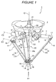
- Figure 1 is a perspective view showing the general configuration of a parallel mechanism according to an embodiment.
- Figure 2 is a diagram showing the parallel mechanism as viewed from the direction of arrow A1 in Figure 1 .
- Figure 3 is a schematic diagram showing an example of an assembled sensing circuit that integrally senses when any of ball joints used in each of arm main bodies composing the parallel mechanism is loose according to the embodiment.
- Figure 4 is a schematic diagram showing how the assembled sensing circuit operates when one of the ball joints comes loose.
- Figure 5 is a schematic diagram showing an example of an assembled sensing circuit that integrally senses when any of ball joints used in each of three arm main bodies composing the parallel mechanism is loose according to the embodiment.
- Figure 6 is a schematic diagram showing an example of an assembled sensing circuit that integrally senses when any of ball joints used in each of three arm main bodies composing the parallel mechanism is loose according to the embodiment.
- Figure 1 is a perspective view showing the general configuration of the parallel mechanism 1 according to the embodiment.
- Figure 2 is a diagram showing the parallel mechanism 1 as viewed from the direction of arrow A1 in Figure 1 .
- the parallel mechanism 1 has a base portion at the top thereof.
- the parallel mechanism 1 is supported by fixing a flat mounting surface 2a of the base portion 2 formed on the bottom surface side thereof, to, for example, a flat ceiling.
- three support members 3 are provided on the bottom surface side of the base portion 2.
- An electric motor 4 is supported in each of the support members 3 as an actuator.
- the electric motor 4 is supported such that the axis C2 of a motor shaft is parallel (that is, horizontal) to the mounting surface 2a of the base portion 2.
- the support members 3 are separated from one another by equal angles (120 degrees) around the vertical axis C1 of the base portion 2.
- the electric motors 4 are also separated from one another by equal angles (120 degrees) around the vertical axis C1 of the base portion 2 (see Figure 2 ).
- a substantially hexagonal cylindrical arm support member 5 is fixed to an output shaft of each of the electric motors 4 coaxially with the axis C2.
- the arm support member 5 is rotated around the axis C2 by driving the electric motor 4.
- Each of the electric motors 4 is connected to an electronic control device (not shown in the drawings; hereinafter also referred to as a "programmable logic controller (PLC)"). Rotation of the output shaft of the electric motor 4 is controlled by the electronic control device.
- PLC programmable logic controller
- the parallel mechanism 1 has three arm main bodies 6.
- Each of the arm main bodies 6 includes a first arm 7 and a second arm 8.
- the first arm 7 corresponds to a first link set forth in Claim 1.
- the second arm 8 corresponds to a second link set forth in Claim 1.
- the first arm 7 is an elongate, hollow cylindrical member formed of, for example, carbon fiber.
- the base end of the first arm 7 is attached to a side surface of the arm support member 5.
- the first arm 7 is fixed so that the axis of the first arm 7 is orthogonal to the axis C2.
- the base end of the second arm 8 is coupled to the free end of the first arm 7 so that the second arm 8 is swingable around the free end of the first arm 7.
- the second arm 8 includes paired elongate rods 9, 10.
- the paired rods 9, 10 are arranged parallel to each other in the longitudinal direction thereof.
- Each of the rods 9, 10 is also an elongate, hollow cylindrical member formed of, for example, carbon fiber.
- the base ends of the rods 9, 10 are rotatably coupled to the free end of the first arm 7 via paired ball joints 16, 17.
- An axis C3 connecting the rotational centers of the ball joints 16, 17 at the base ends of the rods 9, 10 is located parallel to the axis C2 of the electric motor 4.
- each of the coupling members 11, 12 has, for example, a tensile coil spring as a biasing member to bias the paired rods 9, 10 in a direction in which the paired rods 9, 10 pull each other.
- the coupling members 11, 12 may have different structures but preferably has the same structure in terms of reduced costs.
- Each of the coupling members 11, 12 has the function of preventing the rods 9, 19 from rotating around respective axes parallel to the longitudinal direction of the rods 9, 10.
- the parallel mechanism 1 has a bracket 14 to which an end effector portion (tool) 13 is pivotally movably attached.
- the bracket 14 is a substantially equilateral triangular, plate-like member.
- the bracket 14 is held by three arm main bodies 6 so that a mounting surface 14a (the bottom surface of the bracket 14 in Figure 1 ) of the bracket 14 to which the end effector portion 13 is attached is parallel (that is, horizontal) to the mounting surface 2a of the base portion 2.
- a mounting piece 15 is formed on each side of the bracket 14.
- the mounting piece 15 is coupled to the free end (the free ends of the pared rods 9, 10 composing the second arm 8) of the corresponding arm main body 6.
- the bracket 14 thus swings with respect to the corresponding arm main body 6 around the free end of the arm main body 6.
- an end of each of the mounting pieces 15 of the bracket 14 is coupled to the free ends of the corresponding rods 9, 10 via paired ball joints 18, 19.
- An axis C4 (see Figure 2 ) connecting the paired ball joints 18, 19 together is also parallel to the axis C2 of each of the electric motors 4.
- the bracket 14 can swing with respect to each of the arm main bodies 6 around the horizontal axis C4.
- the substantially equilateral triangular bracket 14 is supported by the three arm main bodies 6 so as to be swingable at all the sides thereof around the horizontal axis C4.
- the distance between the paired ball joints 16, 17, located at the coupling portions between the first arm 7 and the second arm 8, is set equal to the distance between the paired ball joints 18, 19, located at the coupling portions between the bracket 14 and the rods 9, 10 of the second arm 8.
- the paired rods 9, 10 composing the second arm are arranged parallel to each other allover the length thereof in the longitudinal direction. All of the axes C2, C3, and C4 are parallel to the mounting surface 2a of the base portion 2.
- the parallel mechanism 1 has a turning shaft rod 20 located in the center thereof and extending in the vertical direction, and an electric motor 21 that rotates the turning shaft rod 20.
- the electric motor 21 is fixed to the base portion 2 with an output shaft thereof directed downward in the vertical direction.
- One end of the turning shaft rod 20 is coupled to the output shaft of the electric motor 21 via a universal joint 22.
- the other end of the turning shaft rod 20 is connected to the end effector portion 13 via a universal joint 23.
- the turning shaft rod 20 is realized by a rod 20a and a cylinder 20b and configured to be telescopic.
- the electric motor 21 is also connected to the above-described electronic control device. Rotation of the output shaft of the electric motor 21 is controlled by the electronic control device to control the rotating position of the end effector portion 13.
- the parallel mechanism 1 has the function of sensing when any of the ball joints 16, 17, 18, 19 is loose for each of the three arm main bodies 6.
- Figure 3 is a schematic diagram showing an example of an assembled sensing circuit that integrally senses when any of a total of four ball joints 16, 17, 18, 19 used in each arm main bodies 8 is loose. Since the assembled sensing circuits for the three arm main bodies 6 are identical, the assembled sensing circuit 44 for one arm main body 6 will be described below. The assembled sensing circuits 44 for the other arm main bodies 6 will not be described.
- Each of the ball joints 16, 17, 18, 19 has, for example, a steel ball stud 30, a metal rod 33 as a socket member, and a conductive member 36.
- the ball stud 30 has a ball-like head 31 located at a tip portion thereof and including an integrally formed spherical outer peripheral surface. Furthermore, a shaft portion 32 is integrally projected from the ball-like head 31 of the ball stud 30.
- the rod 33 includes a socket 35 located at one end thereof and in which a cup 34 is formed; the cup 34 is a semispherical recess portion with an inner peripheral surface corresponding substantially to the spherical outer peripheral surface of the ball-like head 31.
- the cup 34, formed in the socket 35 is configured to hold the ball-like head 31.
- the conductive member 36 is interposed between the cup 34, formed in the socket 35, and the ball-like head 31 of the ball stud 30, held in the cup 34.
- the conductive member 36 is installed in contact with the ball-like head 31 and the cup 34.
- the ball stud 30 and the socket 35 are electrically continuous.
- the ball stud 30, the conductive member 36, and the socket 35 compose a unit sensing circuit that senses when a corresponding one of the ball joints 16, 17, 18, 19 is loose.
- the four unit sensing circuits are connected together in series so as to compose the assembled sensing circuit 44 that integrally senses when any of the ball joints 16, 17, 18, 19 is loose. More specifically, the rod 33 of the ball joint 16 and the rod 33 of the ball joint 18 are electrically connected together via a first wiring material 41. The ball stud 30 (shaft portion 32) of the ball joint 18 and the ball stud 30 (shaft portion 32) of the ball joint 19 are coupled together. The rod 33 of the ball joint 16 and the rod 33 of the ball joint 17 are electrically connected together via a second wiring material 42. Thus, the assembled sensing circuit 44 including the four unit sensing circuits connected together in series is formed. The ball stud 30 (shaft portion 32) of the ball joint 16 and the ball stud 30 (shaft portion 32) of the ball joints 17 are coupled together via an insulator 43.
- the four unit sensing circuits are connected together in series.
- electric continuity is established when all of the total of four ball joints 16, 17, 18, 19, provided in the rods 9, 10.
- the electric continuity is lost when at least any one of the ball joints 16, 17, 18, 19 comes loose (see Figure 4 ).
- a wiring material such as copper wires or pattern wiring can be suitably used as the first wiring material 41 and the second wiring material 42.
- the rods formed of a conductive raw material may be used as a wiring material.
- the first wiring material 41 and the second wiring material 42 are preferably housed in the internal spaces of the hollow rods 9, 10. Thus, the first wiring material 41 and the second wiring material 42 are not exposed to the exterior. This prevents the first wiring material 41 and the second wiring material 42 from being caught on a frame or the like and inadvertently cut while the parallel mechanism 1 is in operation.
- the assembled sensing circuit 44 is connected to a sensing device 40 that senses when any of the ball joints 16, 17, 18, 19 is loose, based on whether or not the assembled sensing circuit 44 is electrically continuous. More specifically, the ball stud 30 (shaft portions 32) of the ball joint 16 and the ball stud 30 (shaft portions 32) of the ball joint 17 are connected to respective input terminals of the sensing device 40 via a third wiring material 46 and a fourth wiring material 47. Alternatively, the following configuration is possible: the ball stud 30 of the ball joint 16 and the ball stud 30 of the ball joint 17 are coupled together, the first wiring material 41 is removed, and the ball stud 30 of the ball joint 16 and the ball stud 30 of the ball joint 18 are connected to the respective input terminals of the sensing device 40.
- the ball stud 30 of the ball joint 16 and the ball stud 30 of the ball joint 17 are coupled together, the second wiring material 42 is removed, and the ball stud 30 of the ball joint 19 and the ball stud 30 of the ball joint 17 are connected to the respective input terminals of the sensing device 40.
- the ball stud 30 of the ball joint 16 and the ball stud 30 of the ball joint 17 are coupled together, the ball stud 30 of the ball joint 18 and the ball stud 30 of the ball joint 19 are coupled together via the insulator 43, and the ball stud 30 of the ball joint 18 and the ball stud 30 of the ball joint 19 are connected to the respective input terminals of the sensing device 40.
- the third wiring material 45 and the fourth wiring material 47 are preferably housed in the internal space of the hollow first arm 7. Thus, the third wiring material 46 and the fourth wiring material 47 are not exposed to the exterior. This prevents the third wiring material 46 or the fourth wiring material 47 from being caught on a frame or the like and inadvertently cut while the parallel mechanism 1 is in operation.
- the sensing device 40 includes an input circuit, a signal processing circuit that processes signals input by the input circuit, and an output circuit that outputs a driving/emergency stop signal to the programmable logic controller (electronic control device), which drives the electric motor 4;
- the input device, the signal processing circuit, and the output circuit are composed of electronic components such as ICs, transistors, resistors, and capacitors.
- the input circuit inputs a Lo (0 V) signal when the electric continuity is present.
- the input circuit inputs a Hi (5 V) signal to the signal processing circuit when the electric continuity is lost.
- the signal processing circuit includes a flip flop to hold the input signal.
- the signal processing circuit executes processes such as prevention of possible chattering of contacts, and outputs the processed signal to the output circuit.
- the signal processing circuit when the electric continuity continuously fails to be sensed for a predetermined time (for example, time required for one cycle of a reciprocating operation), the signal processing circuit outputs a signal indicating that the electric continuity is absent. When the electric continuity is lost, the output circuit outputs the emergency stop signal to the programmable logic controller. That is, the sensing device 40 functions as sensing means and a stop means both set forth in the claims.
- the assembled sensing circuit 44 becomes electrically discontinuous.
- the sensing circuit 44 senses that any of the ball joints 16, 17, 18, 19 is loose.
- the sensing device 40 outputs the emergency stop signal to the programmable logic controller.
- Driving of the electric motor 4 is thus stopped to stop the operation of the parallel mechanism 1.
- the assembled sensing circuit 44 is electrically continuous, and does not output the emergency stop signal.
- the electric motor 4 continues to be driven to allow the parallel mechanism 1 to operate.
- the conductive member 36 is interposed between the ball-like head 31 of the ball stud 30 and the socket 35; the ball stud 30 and the socket 35 compose each of the ball joints 16, 17, 18, 19.
- the ball stud 30 and the socket 35 are electrically continuous via the conductive member 36.
- the ball stud 30 and the socket 35 become electrically discontinuous.
- the present embodiment allows possible loosening of any of the ball joints 16, 17, 18, 19 to be sensed based on whether or not the ball stud 30 and the socket 35 are electrically continuous.
- the present embodiment therefore enables sensing of possible loosening of the ball joints 16, 17, via which one end of the second arm 8 and the other end of the first arm 7 are swingably coupled together, and the ball joints 18, 19, via which the other end of the second arm 8 and the bracket 14 are swingably coupled together.
- the four unit sensing circuits which sense when the ball joints 16, 17, 18, 19, respectively, are loose, are connected together in series so as to compose the assembled sensing circuit 44, which integrally senses when any of the ball joints 16, 17, 18, 19 is loose.
- the assembled sensing circuit 44 becomes electrically discontinuous. Consequently, the assembled sensing circuit 44 can integrally sense when at least any one of the four ball joints 16, 17, 18, 19, provided in the paired rods 9, 10, making up the second arm 8 is loose.
- any of the ball joints 16, 17, 18, 19 is determined to be loose.
- any of the ball joints 16, 17, 18, 19 is determined to be loose.
- the driving of the electric motor 4 is stopped.
- the parallel mechanism 1 can thus be prevented from continuing to operate with the second arm 8 remaining loose from the first arm 7 or the bracket 14.
- the assembled sensing circuit 45 that integrally senses when any of the total of twelve ball joints 16, 17, 18, 19 used in the three arm main bodies 6 is loose, three above-described assembled sensing circuits 44 are connected together in series via a fifth wiring material 48, a sixth wiring material 49, and a seventh wiring material 50.
- the location of the insulator 43 is changed from the one described above.
- the bracket 14 is made of a conductive material such as metal
- the fifth wiring material 48, the sixth wiring material 49, and the seventh wiring material 50 may be formed by performing pattern wiring on an insulating layer provided on the bracket.
- the fifth wiring material 48, the sixth wiring material 49, and the seventh wiring material 50 may be formed by performing pattern wiring directly on the bracket 14. This prevents any of the fifth wiring material 48, the sixth wiring material 49, and the seventh wiring material 50 from being caught on the frame or the like and inadvertently cut while the parallel mechanism 1 is in operation.
- the insulator 43 is provided between the ball stud 30 (shaft portion 32) of the ball joint 16 and the ball stud 30 (shaft portion 32) of the ball joint 17, and also the insulator 43 is provided between the ball stud 30 (shaft portion 32) of the ball joint 18 and the ball stud 30 (shaft portion 32) of the ball joint 19.
- the insulator 43 is provided between the ball stud 30 of the ball joint 18 and the ball stud 30 of the ball joint 19, and the ball stud 30 of the ball joint 16 and the ball stud 30 of the ball joint 17 are coupled together.
- the three assembled sensing circuits 44 (that is, the twelve unit sensing circuits) are connected together in series.
- the assembled sensing circuit 45 is electrically continuous when none of the total of twelve ball joints 16, 17, 18, 19 provided in the three arm main bodies 6 are loose.
- the assembled sensing circuit 45 becomes electrically discontinuous when at least any one of the ball joints 16, 17, 18, 19 is loose.
- the connection to the input terminals of the sensing device 40 are not limited to the ball stud 30 (shaft portion 32) of the ball joint 16 and the ball stud 30 (shaft portion 32) of the ball joint 17, as described above.
- the assembled sensing circuit 45 becomes electrically discontinuous.
- the sensing device 40 thus senses that any of the ball joints 16, 17, 18, 19 is loose. Then, the sensing device 40 outputs the emergency stop signal to the programmable logic controller. The driving of the electric motor 4 is thus stopped to stop the operation of the parallel mechanism 1.
- the assembled sensing circuit 45 is electrically continuous, and does not output the emergency stop signal. Thus, the electric motor 4 continues to be driven to allow the parallel mechanism 1 to operate.
- the three assembled sensing circuits 44 are connected together in series so as to compose the assembled sensing circuit 45, which integrally senses when any of the total of twelve ball joints 16, 17, 18, 19 used in the three arm main bodies 6 (parallel mechanism 1).
- the assembled sensing circuit 45 becomes electrically discontinuous. Therefore, the assembled sensing circuit 45 can integrally sense when at least any one of the total of twelve ball joints 16, 17, 18, 19 used in the three arm main bodies 6 comes loose.
- the present invention has been described. However, the present invention is not limited to the above-described embodiment. Many variations may be made to the embodiment.
- the above-described connection patterns of the assembled sensing circuits 44, 45 are illustrative. The present invention is not limited to these connection patterns.
- the assembled sensing circuit may be configured by sequentially connecting the third wiring material 46 and the fourth wiring material 47 of the other arm main bodies 6 together.
- possible loosening of any of the ball joints 16, 17, 18, 19 is integrally sensed for each of the arm main bodies 6 or for all of the three arm main bodies 6. However, possible loosening may be sensed for each of the ball joints.
- the desired assembled sensing circuit may be configured by optionally selecting the unit sensing circuits corresponding to those of the ball joints 16, 17, 18, 19 for which possible loosening is to be sensed, and connecting the unit sensing circuits together in series.
- the flip flop is used to prevent possible chattering.
- input signals may be processed by software.
- the rod 33 is made of metal.
- the rod 33 may be made of any other material provided that the material is a conductor.
- the rod 33 may be made of a resin containing carbon.
- the rod 33 may be an insulator.
- the first wiring material 42 and the second wiring material 42 may be connected directly to the conductive member 36 as shown in Figure 4 .
- the conductive member 36 may be, such as, an electric piece composing, such as, an ordinary metal leaf spring, or a very wear resistant resin that contains carbon or carbon nanotubes and is thus electrically conductive.
- an electric piece composing such as, an ordinary metal leaf spring, or a very wear resistant resin that contains carbon or carbon nanotubes and is thus electrically conductive.
- POM polyacetal
- PEEK polyether ketone
- the cup 34 may be a conductive member and integrated with the conductive member 36.
Abstract
Description
- This application claims priority under 35 U.S.C. 119 to Japanese Patent Application No.
2008-102969, filed on April 10, 2008 - The present invention relates to a parallel mechanism, and in particular, to a parallel mechanism including a pair of arms coupled together via a ball joint.
- A parallel mechanism is known in which a base portion that is a support base and a bracket with an end effector attached thereto are coupled together in parallel via a plurality of arms. That is, in the parallel mechanism, electric motors are arranged in parallel. Furthermore, a plurality of arms coupled to the respective motors ultimately operate one bracket.
- In each arm, a ball and a socket provided in a ball joint are held by the tensile force of a spring. However, one half side of the ball of the ball joint is exposed from the socket. Thus, when the ball joint is subjected to a load exceed i ng the tensile force of the spr i ng, the ball may come loose from the socket. However, conventional techniques for the parallel mechanism do not take sensing of possible loosening of the ball joint into account. Thus, even if the ball joint comes loose, the parallel mechanism continues to operate with no measures taken, that is, with the ball joint remaining loose. When the parallel mechanism continues to operate with the ball joint remaining loose, the arm or the like may be damaged. Thus, there has been a demand to sense when the ball joint, via which the arms or the like are swingably coupled together, is loose.
- The present invention has been made to solve these problems. The present invention allows sensing of possible loosening of the ball joint, via which the arms or the like are swingably coupled together. A preferred embodiment of the present invention will be described below.
- A preferred embodiment of the present invention provides a parallel mechanism comprising a plurality of arms coupled together in parallel and each including a first link one end of which is coupled to an actuator attached to a base portion, a second link via which other end of the first link and a bracket are coupled together, a ball joint via which one end of the second link and the other end of the first link are swingably coupled together, and a ball joint via which other end of the second link and the bracket are swingably coupled together, wherein the parallel mechanism includes a sensing means for sensing when at least one of the ball joints is loose, and each of the ball joints has a ball stud including a ball-like head, a socket swingably and pivotally movably holding the ball-like head of the ball stud, and a conductive member interposed between the ball-like head and the socket, and wherein the sensing means senses when any of the ball joints is loose, based on whether or not the ball stud and the socket are electrically continuous.
- According to a preferred aspect of the present invention, a conductive member is interposed between the ball-like head of ball stud and the socket; the ball stud and the socket compose the ball joint. Thus, with the ball-like head of the ball stud held in the socket, the ball stud and the socket are electrically continuous via the conductive member. On the other hand, when the ball joint come loose, that is, when the ball-like head of the ball stud comes loose from the socket, the ball stud and the socket becomes electrically discontinuous. Thus, possible loosening of the ball joint can be sensed based on whether or not the ball stud and the socket are electrically continuous. This enables sensing of possible loosening of the ball joint via which the one end of the second link and the other end of the first link are swingably coupled together and/or the ball joint via which the other end of the second link and the bracket are swingably coupled together.
- In a more preferred aspect, the sensing means senses when any of the ball joints is loose, based on whether or not a unit sensing circuit formed of the ball stud, the conductive member, and the socket is electrically continuous.
- In this case, possible loosening can be sensed for each of the ball joints.
- In a more preferred aspect, the sensing means senses when any of the ball joints is loose, based on whether or not an assembled sensing circuit is electrically continuous in which a plurality of unit sensing circuits each formed of the ball stud, the conductive member, and the socket are connected together in series.
- Thus, the assembled sensing circuit becomes electrically discontinuous when at least any one of the plurality of ball joints composing the plurality of unit sensing circuits included in the assembled sensing circuit comes loose.
Consequently, possible loosening of the ball joints can be integrally sensed. - In a more preferred aspect, the second link has paired rods. The ball joint via which the one end of the second link and the other end of the first link are coupled together and the ball joint via which the other end of the second link and the bracket are coupled together are provided in the respective paired rods as a pair. In the assembled sensing circuit, the unit sensing circuits each formed for the four ball joints provided in the second link are connected together in series.
- In this case, the electric continuity of the assembled sensing circuit becomes electrically discontinuous when at least any one of a total of four ball joints provided in the paired rods composing the second link comes loose. Thus, the sensing circuit can integrally sense when any of the four ball joints provided in the paired rods is loose.
- Furthermore, preferably, the parallel mechanism includes three arms, and the second link has paired rods. The ball joint via which the one end of the second link and the other end of the first link are coupled together and the ball joint via which the other end of the second link and the bracket are provided in paired rods, respectively, as a pair. In the assembled sensing circuit, the unit sensing circuits formed for the twelve ball joints provided in the three arms are connected together in series.
- Thus, the assembled sensing circuit becomes electrically discontinuous when at least any one of a total of twelve ball joints used in the three arms composing the one parallel mechanism comes loose. Consequently, the sensing circuit can integrally sense when any of the twelve ball joints used in the three arms is loose.
- In a more preferred aspect of the present invention, the sensing means determines that any of the ball joints is loose when the ball joint remains electrically discontinuous at least for a predetermined time.
- Thus, even if instantaneous interruption or chattering occurs during operation of the parallel mechanism, possible erroneous sensing can be prevented.
- In a more preferred aspect of the present invention, the parallel mechanism includes a stop means for stopping driving of the actuator when the sensing means determines that any of the ball joints is loose.
- Thus, when any of the ball joints comes loose, the driving of the actuator is stopped. The parallel mechanism can thus be prevented from continuing to operate with the second link loose from the first link or the bracket.
- Other features, elements, processes, steps, characteristics and advantages of the present invention will become more apparent from the following detailed description of preferred embodiments of the present invention with reference to the attached drawings.
-
Figure 1 is a perspective view showing the general configuration of a parallel mechanism according to an embodiment. -
Figure 2 is a diagram showing the parallel mechanism as viewed from the direction of arrow A1 inFigure 1 . -
Figure 3 is a schematic diagram showing an example of an assembled sensing circuit that integrally senses when any of ball joints used in each of arm main bodies composing the parallel mechanism is loose according to the embodiment. -
Figure 4 is a schematic diagram showing how the assembled sensing circuit operates when one of the ball joints comes loose. -
Figure 5 is a schematic diagram showing an example of an assembled sensing circuit that integrally senses when any of ball joints used in each of three arm main bodies composing the parallel mechanism is loose according to the embodiment. -
Figure 6 is a schematic diagram showing an example of an assembled sensing circuit that integrally senses when any of ball joints used in each of three arm main bodies composing the parallel mechanism is loose according to the embodiment. - A preferred embodiment of the present invention will be described below in detail with reference to the drawings. In the drawings, the same elements are denoted by the same reference numerals, and duplicate descriptions are omitted.
- First, the general configuration of a parallel mechanism according to the embodiment will be described with reference to
Figures 1 and2 .Figure 1 is a perspective view showing the general configuration of theparallel mechanism 1 according to the embodiment.Figure 2 is a diagram showing theparallel mechanism 1 as viewed from the direction of arrow A1 inFigure 1 . - The
parallel mechanism 1 has a base portion at the top thereof. Theparallel mechanism 1 is supported by fixing aflat mounting surface 2a of thebase portion 2 formed on the bottom surface side thereof, to, for example, a flat ceiling. On the other hand, threesupport members 3 are provided on the bottom surface side of thebase portion 2. Anelectric motor 4 is supported in each of thesupport members 3 as an actuator. Theelectric motor 4 is supported such that the axis C2 of a motor shaft is parallel (that is, horizontal) to themounting surface 2a of thebase portion 2. Thesupport members 3 are separated from one another by equal angles (120 degrees) around the vertical axis C1 of thebase portion 2. Theelectric motors 4 are also separated from one another by equal angles (120 degrees) around the vertical axis C1 of the base portion 2 (seeFigure 2 ). - A substantially hexagonal cylindrical
arm support member 5 is fixed to an output shaft of each of theelectric motors 4 coaxially with the axis C2. Thearm support member 5 is rotated around the axis C2 by driving theelectric motor 4. Each of theelectric motors 4 is connected to an electronic control device (not shown in the drawings; hereinafter also referred to as a "programmable logic controller (PLC)"). Rotation of the output shaft of theelectric motor 4 is controlled by the electronic control device. - The
parallel mechanism 1 has three armmain bodies 6. Each of the armmain bodies 6 includes afirst arm 7 and asecond arm 8. Here, thefirst arm 7 corresponds to a first link set forth inClaim 1. Thesecond arm 8 corresponds to a second link set forth inClaim 1. Thefirst arm 7 is an elongate, hollow cylindrical member formed of, for example, carbon fiber. The base end of thefirst arm 7 is attached to a side surface of thearm support member 5. Thefirst arm 7 is fixed so that the axis of thefirst arm 7 is orthogonal to the axis C2. - The base end of the
second arm 8 is coupled to the free end of thefirst arm 7 so that thesecond arm 8 is swingable around the free end of thefirst arm 7. Thesecond arm 8 includes pairedelongate rods rods rods rods first arm 7 via paired ball joints 16, 17. An axis C3 connecting the rotational centers of the ball joints 16, 17 at the base ends of therods electric motor 4. - Furthermore, at the base end of the
second arm 8, therod 9 and theother rod 10 are coupled together via acoupling member 11. At the free end of thesecond arm 8, therod 9 and theother rod 10 are coupled together via acoupling member 12. Each of thecoupling members rods rods coupling members coupling members rods rods - Furthermore, the
parallel mechanism 1 has abracket 14 to which an end effector portion (tool) 13 is pivotally movably attached. Thebracket 14 is a substantially equilateral triangular, plate-like member. Thebracket 14 is held by three armmain bodies 6 so that a mountingsurface 14a (the bottom surface of thebracket 14 inFigure 1 ) of thebracket 14 to which theend effector portion 13 is attached is parallel (that is, horizontal) to the mountingsurface 2a of thebase portion 2. - A mounting
piece 15 is formed on each side of thebracket 14. The mountingpiece 15 is coupled to the free end (the free ends of the paredrods main body 6. Thebracket 14 thus swings with respect to the corresponding armmain body 6 around the free end of the armmain body 6. Specifically, an end of each of the mountingpieces 15 of thebracket 14 is coupled to the free ends of the correspondingrods Figure 2 ) connecting the paired ball joints 18, 19 together is also parallel to the axis C2 of each of theelectric motors 4. Thus, thebracket 14 can swing with respect to each of the armmain bodies 6 around the horizontal axis C4. The substantially equilateraltriangular bracket 14 is supported by the three armmain bodies 6 so as to be swingable at all the sides thereof around the horizontal axis C4. - The distance between the paired ball joints 16, 17, located at the coupling portions between the
first arm 7 and thesecond arm 8, is set equal to the distance between the paired ball joints 18, 19, located at the coupling portions between thebracket 14 and therods second arm 8. Thus, as described above, the pairedrods surface 2a of thebase portion 2. Thus, regardless of however thefirst arm 7, thesecond arm 8, and thebracket 14 swing around the axes C2, C3, and C4, respectively, the parallel relationship is maintained between the mountingsurface 14a of thebracket 14 to which theend effector portion 13 is attached and the mountingsurface 2a of thebase portion 2. - In response to instructions from the electronic control device, the rotating position of the
arm support member 5 fixed to the output shaft of each of theelectric motors 4 is controlled to control the position of the free end of the correspondingfirst arm 7. The position of the free end of each of thesecond arms 8 follows the controlled position of the free end of the correspondingfirst arm 7. This determines the position of the mountingsurface 14a of thebracket 14 to which theend effector portion 13 is attached. At this time, as described above, thebracket 14 moves with the horizontal posture thereof maintained. - Furthermore, the
parallel mechanism 1 has a turningshaft rod 20 located in the center thereof and extending in the vertical direction, and anelectric motor 21 that rotates the turningshaft rod 20. Theelectric motor 21 is fixed to thebase portion 2 with an output shaft thereof directed downward in the vertical direction. One end of the turningshaft rod 20 is coupled to the output shaft of theelectric motor 21 via auniversal joint 22. On the other hand, the other end of the turningshaft rod 20 is connected to theend effector portion 13 via auniversal joint 23. The turningshaft rod 20 is realized by arod 20a and acylinder 20b and configured to be telescopic. Since theuniversal joints shaft rod 20, even though thebracket 14 is drivingly moved to a predetermined upward, downward, forward, backward, rightward, or leftward position by the threeelectric motors 4, the turningshaft rod 20 can move following the predetermined position. Theelectric motor 21 is also connected to the above-described electronic control device.
Rotation of the output shaft of theelectric motor 21 is controlled by the electronic control device to control the rotating position of theend effector portion 13. - Furthermore, the
parallel mechanism 1 has the function of sensing when any of the ball joints 16, 17, 18, 19 is loose for each of the three armmain bodies 6. Now, with reference toFigure 3 , an assembled sensing circuit and a sensing device which detect when any of the ball joints 16, 17, 18, 19 is loose. Here,Figure 3 is a schematic diagram showing an example of an assembled sensing circuit that integrally senses when any of a total of fourball joints main bodies 8 is loose. Since the assembled sensing circuits for the three armmain bodies 6 are identical, the assembledsensing circuit 44 for one armmain body 6 will be described below. The assembledsensing circuits 44 for the other armmain bodies 6 will not be described. - Each of the ball joints 16, 17, 18, 19 has, for example, a
steel ball stud 30, ametal rod 33 as a socket member, and aconductive member 36. Theball stud 30 has a ball-like head 31 located at a tip portion thereof and including an integrally formed spherical outer peripheral surface. Furthermore, ashaft portion 32 is integrally projected from the ball-like head 31 of theball stud 30. On the other hand, therod 33 includes asocket 35 located at one end thereof and in which acup 34 is formed; thecup 34 is a semispherical recess portion with an inner peripheral surface corresponding substantially to the spherical outer peripheral surface of the ball-like head 31. Thecup 34, formed in thesocket 35, is configured to hold the ball-like head 31. - The
conductive member 36 is interposed between thecup 34, formed in thesocket 35, and the ball-like head 31 of theball stud 30, held in thecup 34. Theconductive member 36 is installed in contact with the ball-like head 31 and thecup 34. Thus, with the ball-like head 31 of theball stud 30 held in thecup 34, formed in thesocket 35, theball stud 30 and thesocket 35 are electrically continuous. Furthermore, when any of the ball joints 16, 17, 18, 19 is loose, that is, when the ball-like head 31 of theball stud 30 is loose from thecup 34, formed in thesocket 35, theball stud 30 and thesocket 35 are electrically discontinuous. Namely, theball stud 30, theconductive member 36, and thesocket 35 compose a unit sensing circuit that senses when a corresponding one of the ball joints 16, 17, 18, 19 is loose. - The four unit sensing circuits are connected together in series so as to compose the assembled
sensing circuit 44 that integrally senses when any of the ball joints 16, 17, 18, 19 is loose. More specifically, therod 33 of the ball joint 16 and therod 33 of the ball joint 18 are electrically connected together via afirst wiring material 41. The ball stud 30 (shaft portion 32) of the ball joint 18 and the ball stud 30 (shaft portion 32) of the ball joint 19 are coupled together. Therod 33 of the ball joint 16 and therod 33 of the ball joint 17 are electrically connected together via asecond wiring material 42. Thus, the assembledsensing circuit 44 including the four unit sensing circuits connected together in series is formed. The ball stud 30 (shaft portion 32) of the ball joint 16 and the ball stud 30 (shaft portion 32) of the ball joints 17 are coupled together via aninsulator 43. - In the assembled
sensing circuit 44, the four unit sensing circuits are connected together in series. Thus, electric continuity is established when all of the total of fourball joints rods Figure 4 ). For example, a wiring material such as copper wires or pattern wiring can be suitably used as thefirst wiring material 41 and thesecond wiring material 42. However, the rods formed of a conductive raw material may be used as a wiring material. Thefirst wiring material 41 and thesecond wiring material 42 are preferably housed in the internal spaces of thehollow rods first wiring material 41 and thesecond wiring material 42 are not exposed to the exterior. This prevents thefirst wiring material 41 and thesecond wiring material 42 from being caught on a frame or the like and inadvertently cut while theparallel mechanism 1 is in operation. - The assembled
sensing circuit 44 is connected to asensing device 40 that senses when any of the ball joints 16, 17, 18, 19 is loose, based on whether or not the assembledsensing circuit 44 is electrically continuous. More specifically, the ball stud 30 (shaft portions 32) of the ball joint 16 and the ball stud 30 (shaft portions 32) of the ball joint 17 are connected to respective input terminals of thesensing device 40 via athird wiring material 46 and afourth wiring material 47. Alternatively, the following configuration is possible: theball stud 30 of the ball joint 16 and theball stud 30 of the ball joint 17 are coupled together, thefirst wiring material 41 is removed, and theball stud 30 of the ball joint 16 and theball stud 30 of the ball joint 18 are connected to the respective input terminals of thesensing device 40. Alternatively, the following configuration is possible: theball stud 30 of the ball joint 16 and theball stud 30 of the ball joint 17 are coupled together, thesecond wiring material 42 is removed, and theball stud 30 of the ball joint 19 and theball stud 30 of the ball joint 17 are connected to the respective input terminals of thesensing device 40. Alternatively, the following configuration is possible: theball stud 30 of the ball joint 16 and theball stud 30 of the ball joint 17 are coupled together, theball stud 30 of the ball joint 18 and theball stud 30 of the ball joint 19 are coupled together via theinsulator 43, and theball stud 30 of the ball joint 18 and theball stud 30 of the ball joint 19 are connected to the respective input terminals of thesensing device 40. Thethird wiring material 45 and thefourth wiring material 47 are preferably housed in the internal space of the hollowfirst arm 7. Thus, thethird wiring material 46 and thefourth wiring material 47 are not exposed to the exterior. This prevents thethird wiring material 46 or thefourth wiring material 47 from being caught on a frame or the like and inadvertently cut while theparallel mechanism 1 is in operation. - The
sensing device 40 includes an input circuit, a signal processing circuit that processes signals input by the input circuit, and an output circuit that outputs a driving/emergency stop signal to the programmable logic controller (electronic control device), which drives theelectric motor 4; the input device, the signal processing circuit, and the output circuit are composed of electronic components such as ICs, transistors, resistors, and capacitors. For example, the input circuit inputs a Lo (0 V) signal when the electric continuity is present. The input circuit inputs a Hi (5 V) signal to the signal processing circuit when the electric continuity is lost. The signal processing circuit includes a flip flop to hold the input signal. The signal processing circuit executes processes such as prevention of possible chattering of contacts, and outputs the processed signal to the output circuit. Furthermore, when the electric continuity continuously fails to be sensed for a predetermined time (for example, time required for one cycle of a reciprocating operation), the signal processing circuit outputs a signal indicating that the electric continuity is absent. When the electric continuity is lost, the output circuit outputs the emergency stop signal to the programmable logic controller. That is, thesensing device 40 functions as sensing means and a stop means both set forth in the claims. - In the above-described configuration, when during operation of the
parallel mechanism 1, at least any one of the ball joints 16, 17, 18, 19 composing the assembledsensing circuit 44 comes loose, the assembledsensing circuit 44 becomes electrically discontinuous. Thus, thesensing circuit 44 senses that any of the ball joints 16, 17, 18, 19 is loose. Then, thesensing device 40 outputs the emergency stop signal to the programmable logic controller. Driving of theelectric motor 4 is thus stopped to stop the operation of theparallel mechanism 1. On the other hand, when none of the ball joints 16, 17, 18, 19 are loose, the assembledsensing circuit 44 is electrically continuous, and does not output the emergency stop signal. Thus, theelectric motor 4 continues to be driven to allow theparallel mechanism 1 to operate. - According to the present embodiment, the
conductive member 36 is interposed between the ball-like head 31 of theball stud 30 and thesocket 35; theball stud 30 and thesocket 35 compose each of the ball joints 16, 17, 18, 19. Thus, with the ball-like head 31 of theball stud 30 held in thesocket 35, theball stud 30 and thesocket 35 are electrically continuous via theconductive member 36. On the other hand, when any of the ball joints 16, 17, 18, 19 comes loose, that is, when the ball-like head 31 of theball stud 30 comes loose from thesocket 35, theball stud 30 and thesocket 35 become electrically discontinuous. Thus, the present embodiment allows possible loosening of any of the ball joints 16, 17, 18, 19 to be sensed based on whether or not theball stud 30 and thesocket 35 are electrically continuous. The present embodiment therefore enables sensing of possible loosening of the ball joints 16, 17, via which one end of thesecond arm 8 and the other end of thefirst arm 7 are swingably coupled together, and the ball joints 18, 19, via which the other end of thesecond arm 8 and thebracket 14 are swingably coupled together. - According to the present embodiment, the four unit sensing circuits, which sense when the ball joints 16, 17, 18, 19, respectively, are loose, are connected together in series so as to compose the assembled
sensing circuit 44, which integrally senses when any of the ball joints 16, 17, 18, 19 is loose. Thus, when at least any one of the ball joints 16, 17, 18, 19, composing the assembledsensing circuit 44, comes loose, the assembledsensing circuit 44 becomes electrically discontinuous. Consequently, the assembledsensing circuit 44 can integrally sense when at least any one of the fourball joints rods second arm 8 is loose. - According to the present embodiment, when the assembled
sensing circuit 44 is electrically discontinuous at least for the predetermined time, any of the ball joints 16, 17, 18, 19 is determined to be loose. Thus, even if instantaneous interruption or chattering occurs during operation of theparallel mechanism 1, possible erroneous sensing can be prevented. - Furthermore, according to the present embodiment, when any of the ball joints 16, 17, 18, 19 comes loose, the driving of the
electric motor 4 is stopped. Theparallel mechanism 1 can thus be prevented from continuing to operate with thesecond arm 8 remaining loose from thefirst arm 7 or thebracket 14. - In the above-described assembled
sensing circuit 44, possible loosening of any of the ball joints 16, 17, 18, 19 is sensed for any one of the armmain bodies 6 or for each of the armmain bodies 6. However, the three assembledsensing circuits 44, provided for the respective armmain bodies 6, may be connected together in series so as to integrally sense when any of a total of twelveball joints 16 to 19 used in the three arm main bodies 6 (parallel mechanism 1) is loose (a second wiring form). Thus, subsequently, with reference toFigure 5 , an assembledsensing circuit 44 will be described which integrally senses when any of the total of twelveball joints main bodies 6 is loose. Here,Figure 5 is a schematic diagram showing an example of an assembled sensing circuit that integrally senses when any of the total of twelveball joints main bodies 6 is loose. - As shown in
Figure 5 , in the assembledsensing circuit 45 that integrally senses when any of the total of twelveball joints main bodies 6 is loose, three above-described assembledsensing circuits 44 are connected together in series via afifth wiring material 48, asixth wiring material 49, and aseventh wiring material 50. In this case, to allow the assembledsensing circuits 44 composing the assembledsensing circuit 45 to be connected together in series, the location of theinsulator 43 is changed from the one described above. When thebracket 14 is made of a conductive material such as metal, thefifth wiring material 48, thesixth wiring material 49, and theseventh wiring material 50 may be formed by performing pattern wiring on an insulating layer provided on the bracket. Where thebracket 14 is made of an insulating material such as resin, thefifth wiring material 48, thesixth wiring material 49, and theseventh wiring material 50 may be formed by performing pattern wiring directly on thebracket 14. This prevents any of thefifth wiring material 48, thesixth wiring material 49, and theseventh wiring material 50 from being caught on the frame or the like and inadvertently cut while theparallel mechanism 1 is in operation. - In the assembled
sensing circuit 44 connected to thesensing device 40, theinsulator 43 is provided between the ball stud 30 (shaft portion 32) of the ball joint 16 and the ball stud 30 (shaft portion 32) of the ball joint 17, and also theinsulator 43 is provided between the ball stud 30 (shaft portion 32) of the ball joint 18 and the ball stud 30 (shaft portion 32) of the ball joint 19. On the other hand, in the assembledsensing circuit 44 not connected to thesensing device 40, theinsulator 43 is provided between theball stud 30 of the ball joint 18 and theball stud 30 of the ball joint 19, and theball stud 30 of the ball joint 16 and theball stud 30 of the ball joint 17 are coupled together. The remaining part of the configuration of the assembledsensing circuit 44 and the configuration of thesensing device 40 are as described above and will thus not be described below. - In the assembled
sensing circuit 45, the three assembled sensing circuits 44 (that is, the twelve unit sensing circuits) are connected together in series.
Thus, the assembledsensing circuit 45 is electrically continuous when none of the total of twelveball joints main bodies 6 are loose. The assembledsensing circuit 45 becomes electrically discontinuous when at least any one of the ball joints 16, 17, 18, 19 is loose. The connection to the input terminals of thesensing device 40 are not limited to the ball stud 30 (shaft portion 32) of the ball joint 16 and the ball stud 30 (shaft portion 32) of the ball joint 17, as described above. - In the above-described configuration, when at least any one of the ball joints 16, 17, 18, 19, composing the assembled
sensing circuit 45, is loose, the assembledsensing circuit 45 becomes electrically discontinuous. Thesensing device 40 thus senses that any of the ball joints 16, 17, 18, 19 is loose. Then, thesensing device 40 outputs the emergency stop signal to the programmable logic controller. The driving of theelectric motor 4 is thus stopped to stop the operation of theparallel mechanism 1. On the other hand, when none of the ball joints 16, 17, 18, 19 are loose, the assembledsensing circuit 45 is electrically continuous, and does not output the emergency stop signal. Thus, theelectric motor 4 continues to be driven to allow theparallel mechanism 1 to operate. - According to the present invention, the three assembled
sensing circuits 44 are connected together in series so as to compose the assembledsensing circuit 45, which integrally senses when any of the total of twelveball joints sensing circuit 45 is loose, the assembledsensing circuit 45 becomes electrically discontinuous. Therefore, the assembledsensing circuit 45 can integrally sense when at least any one of the total of twelveball joints main bodies 6 comes loose. - The embodiment of the present invention has been described. However, the present invention is not limited to the above-described embodiment. Many variations may be made to the embodiment. For example, the above-described connection patterns of the assembled
sensing circuits Figure 6 , the assembled sensing circuit may be configured by sequentially connecting thethird wiring material 46 and thefourth wiring material 47 of the other armmain bodies 6 together. Furthermore, in the above-described embodiment, possible loosening of any of the ball joints 16, 17, 18, 19 is integrally sensed for each of the armmain bodies 6 or for all of the three armmain bodies 6. However, possible loosening may be sensed for each of the ball joints. In this case, which of the ball joints 16, 17, 18, 19 are loose can also be determined. Moreover, the desired assembled sensing circuit may be configured by optionally selecting the unit sensing circuits corresponding to those of the ball joints 16, 17, 18, 19 for which possible loosening is to be sensed, and connecting the unit sensing circuits together in series. - In the above-described embodiment, when the sensing circuit senses that any of the ball joints 16, 17, 18, 19 are loose, the
electric motor 4 is stopped.
However, an alarm may be used in addition to or instead of the stop of theelectric motor 4. - Furthermore, in the above-described embodiment, the flip flop is used to prevent possible chattering. However, input signals may be processed by software.
- In the above-described embodiment, the
rod 33 is made of metal. However, therod 33 may be made of any other material provided that the material is a conductor. For example, therod 33 may be made of a resin containing carbon. Alternatively, therod 33 may be an insulator. In this case, thefirst wiring material 42 and thesecond wiring material 42 may be connected directly to theconductive member 36 as shown inFigure 4 . - The
conductive member 36 may be, such as, an electric piece composing, such as, an ordinary metal leaf spring, or a very wear resistant resin that contains carbon or carbon nanotubes and is thus electrically conductive. For example, POM (polyacetal), PEEK (polyether ketone), or the like is preferable in which carbon nanotubes are mixed with PTFE. Moreover, thecup 34 may be a conductive member and integrated with theconductive member 36. - While the present invention has been described with respect to preferred embodiments thereof, it will be apparent to those skilled in the art that the disclosed invention may be modified in numerous ways and may assume many embodiments other than those specifically set out and described above. Accordingly, it is intended by the appended claims to cover all modifications of the present invention that fall within the true spirit and scope of the present invention.
Claims (7)
- A parallel mechanism (1) comprising a plurality of arms (6) coupled together in parallel and each arms (6) including a first link (7) one end of which is coupled to an actuator (4) attached to a base portion (2), a second link (8) via which other end of the first link (7) and a bracket (14) are coupled together, a ball joint (16, 17) via which one end of the second link (8) and the other end of the first link (7) are swingably coupled together, and a ball joint (18, 19) via which other end of the second link (8) and the bracket (14) are swingably coupled together, the parallel mechanism being characterized in that:the parallel mechanism includes a sensing means (44) for sensing when at least one of the ball joints (16, 17, 18, 19) is loose,each of the ball joints (16, 17, 18, 19) has a ball stud (30) including a ball-like head (31), a socket (35) swingably holding the ball-like head (31) of the ball stud (30), and a conductive member (36) interposed between the ball-like head (31) and the socket (35), andthe sensing means (44) senses when any of the ball joints (16, 17, 18, 19) is loose, based on whether or not the ball stud (30) and the socket (35) are electrically continuous.
- The parallel mechanism (1) according to Claim 1, characterized in that the sensing means (44) senses when any of the ball joints (16, 17, 18, 19) is loose, based on whether or not a unit sensing circuit formed of the ball stud (30), the conductive member (36), and the socket (35) is electrically continuous.
- The parallel mechanism (1) according to Claim 1, characterized in that the sensing means (44) senses when any of the ball joints (16, 17, 18, 19) is loose, based on whether or not an assembled sensing circuit is electrically continuous in which a plurality of unit sensing circuits each formed of the ball stud (30), the conductive member (36) and the socket (35), are connected together in series.
- The parallel mechanism according to Claim 3, characterized in that the second link (8) has paired rods (9, 10),
the ball joint (16, 17) via which the one end of the second link (8) and the other end of the first link (7) are coupled together and the ball joint (18, 19) via which the other end of the second link (8) and the bracket (14) are coupled together are provided in the respective paired rods (9, 10) as a pair, and
in the assembled sensing circuit (44), the unit sensing circuits each formed for the four ball joints (16, 17, 18, 19) provided in the second link (8) are connected together in series. - The parallel mechanism according to Claim 3, characterized in that the parallel mechanism (1) comprises three arms (6),
the second link (8) has paired rods (9, 10),
the ball joint (16, 17) via which the one end of the second link (8) and the other end of the first link (7) are coupled together and the ball joint (18, 19) via which the other end of the second link (8) and the bracket (14) are provided in the respective paired rods (9, 10) as a pair,
in the assembled sensing circuit (44), the unit sensing circuits formed for the twelve ball joints (16, 17, 18, 19) provided in the three arms (6) are connected together in series. - The parallel mechanism (1) according to any one of Claims 1 to 5, characterized in that the sensing means (44) determines that any of the ball joints (16, 17, 18, 19) is loose when the ball joint remains electrically discontinuous at least for a predetermined time.
- The parallel mechanism according to any one of Claims 1 to 6, characterized by further including a stop control means (PLC) for stopping driving of the actuator (4) when the sensing device (44) determines that any of the ball joints (16, 17, 18, 19) is loose.
Applications Claiming Priority (1)
| Application Number | Priority Date | Filing Date | Title |
|---|---|---|---|
| JP2008102969A JP4850863B2 (en) | 2008-04-10 | 2008-04-10 | Parallel mechanism |
Publications (2)
| Publication Number | Publication Date |
|---|---|
| EP2116339A1 true EP2116339A1 (en) | 2009-11-11 |
| EP2116339B1 EP2116339B1 (en) | 2010-11-10 |
Family
ID=40592525
Family Applications (1)
| Application Number | Title | Priority Date | Filing Date |
|---|---|---|---|
| EP09003960A Not-in-force EP2116339B1 (en) | 2008-04-10 | 2009-03-19 | Parallel mechanism |
Country Status (8)
| Country | Link |
|---|---|
| US (1) | US8132481B2 (en) |
| EP (1) | EP2116339B1 (en) |
| JP (1) | JP4850863B2 (en) |
| KR (1) | KR101300518B1 (en) |
| CN (1) | CN101554727B (en) |
| DE (1) | DE602009000328D1 (en) |
| ES (1) | ES2354011T3 (en) |
| TW (1) | TW200944347A (en) |
Cited By (6)
| Publication number | Priority date | Publication date | Assignee | Title |
|---|---|---|---|---|
| WO2010069298A1 (en) * | 2008-12-19 | 2010-06-24 | Elau Gmbh | Delta robot having special arrangement of the ball joints |
| EP2818285A1 (en) * | 2013-06-27 | 2014-12-31 | Delaware Capital Formation, Inc. | Boom utilized in a geometric end effector system |
| EP2952304A1 (en) * | 2014-06-03 | 2015-12-09 | Siemens Aktiengesellschaft | Method and device for detecting an improper load on an element |
| CZ306033B6 (en) * | 2012-02-13 | 2016-07-07 | ÄŚVUT v Praze, Fakulta strojnĂ | Method of setting position of transfer arms on a supporting frame and transfer arms for gripping technological or measuring means |
| EP2954985A4 (en) * | 2013-02-08 | 2018-08-01 | Matriruiz, S.L. | Set of mechanical means that can be incorporated into a delta robot for the gumming of lids |
| EP3348359A4 (en) * | 2015-09-08 | 2019-04-10 | Kawasaki Jukogyo Kabushiki Kaisha | Robot |
Families Citing this family (44)
| Publication number | Priority date | Publication date | Assignee | Title |
|---|---|---|---|---|
| JP4420959B2 (en) * | 2008-04-10 | 2010-02-24 | 村田機械株式会社 | Parallel mechanism |
| DE102008001314A1 (en) * | 2008-04-22 | 2009-10-29 | Robert Bosch Gmbh | Device for moving and positioning an object in space |
| DE102008025845B4 (en) * | 2008-05-29 | 2013-07-11 | Festo Ag & Co. Kg | drive system |
| US9370867B2 (en) * | 2009-08-04 | 2016-06-21 | Majatronic Gmbh | Parallel robot |
| CN101708611B (en) * | 2009-11-09 | 2011-07-27 | 天津大学 | Parallel mechanism with three-dimensional translation and one-dimensional rotation |
| CN102069499B (en) * | 2009-11-19 | 2013-08-28 | 鸿富锦精密工业(深圳)有限公司 | Parallel robot |
| CN102069495B (en) * | 2009-11-23 | 2014-01-22 | 鸿富锦精密工业(深圳)有限公司 | Parallel robot |
| US8601897B2 (en) * | 2009-11-30 | 2013-12-10 | GM Global Technology Operations LLC | Force limiting device and method |
| WO2011114723A1 (en) * | 2010-03-17 | 2011-09-22 | パナソニック株式会社 | Parallel link robot, and method of teaching parallel link robot |
| CN102441889A (en) * | 2010-09-30 | 2012-05-09 | 鸿富锦精密工业(深圳)有限公司 | Parallel-connection robot |
| JP5408211B2 (en) * | 2011-09-06 | 2014-02-05 | 株式会社安川電機 | Parallel link robot, parallel link robot system, and parallel link robot control method |
| WO2013047414A1 (en) | 2011-09-29 | 2013-04-04 | Ntn株式会社 | Link actuating device |
| JP5951224B2 (en) | 2011-11-02 | 2016-07-13 | Ntn株式会社 | Method for initial setting of origin position of link actuator and link actuator |
| US9630326B2 (en) * | 2011-11-08 | 2017-04-25 | Ross-Hime Designs, Inc. | Robotic manipulator with spherical joints |
| CN102490187B (en) * | 2011-12-13 | 2013-12-25 | 天津大学 | Parallel manipulator with five freedom degrees |
| CN102490186B (en) * | 2011-12-13 | 2013-12-18 | 天津大学 | Four-degree-of-freedom parallel manipulator |
| CN102490185B (en) * | 2011-12-13 | 2014-05-21 | 天津大学 | Face-symmetry five-freedom-degree parallel-connection manipulator |
| JP5888988B2 (en) * | 2012-01-06 | 2016-03-22 | 日本電産サンキョー株式会社 | Industrial robot |
| KR101419897B1 (en) * | 2012-04-26 | 2014-07-15 | 고려대학교 산학협력단 | 5-dof micro robot of parallel-type |
| CN102773856A (en) * | 2012-08-29 | 2012-11-14 | 江西省机械科学研究所 | Space five-FOD (Degree of Freedom) mechanism for independently controlling rotational motion and translational motion |
| JP5674734B2 (en) * | 2012-08-31 | 2015-02-25 | ファナック株式会社 | Parallel link robot connected by ball joint |
| JP5977137B2 (en) * | 2012-10-04 | 2016-08-24 | ヤマハ発動機株式会社 | Rotating shaft and industrial robot equipped with the rotating shaft |
| DE102013208082A1 (en) * | 2013-05-02 | 2014-11-06 | Krones Aktiengesellschaft | Device for handling articles |
| DE102013106004A1 (en) * | 2013-06-10 | 2014-12-11 | Krones Aktiengesellschaft | Device for handling articles and method for operating such a device |
| CN103448059B (en) * | 2013-08-19 | 2015-11-18 | 燕山大学 | Containing planar six-rod closed loop side chain 6DOF parallel institution |
| JP5723426B2 (en) * | 2013-09-02 | 2015-05-27 | 株式会社カイジョー | Drive mechanism and manufacturing apparatus |
| CN103753521B (en) * | 2014-01-17 | 2016-06-29 | 天津大学 | A kind of pinion and-rack four-degree-of-freedom high speed parallel robot |
| CN103817689B (en) * | 2014-02-12 | 2017-08-25 | 青岛汇智智能系统工程有限公司 | A kind of parallel robot lower shoe |
| CN103786148A (en) * | 2014-02-12 | 2014-05-14 | 青岛汇智机器人有限公司 | Lower chassis of parallel robot |
| CN103802094A (en) * | 2014-02-14 | 2014-05-21 | 青岛汇智机器人有限公司 | Parallel robot |
| CN104526681B (en) * | 2014-12-25 | 2016-05-04 | 东莞理工学院 | Parallel manipulator |
| DE102015211344B4 (en) * | 2015-06-19 | 2019-06-27 | Krones Aktiengesellschaft | Device for handling articles and methods for detecting wear in such a handling device |
| JP6502194B2 (en) * | 2015-06-30 | 2019-04-17 | ヤマハ発動機株式会社 | Industrial robot |
| JP6374439B2 (en) | 2016-06-03 | 2018-08-15 | ファナック株式会社 | Abnormality detection device and abnormality detection method for joint part of parallel link robot |
| CN106272348B (en) * | 2016-08-31 | 2019-05-28 | 上海交通大学 | The mixed connection mechanism for sorting for moving two turns of five degree of freedom with three |
| CN106272346A (en) * | 2016-08-31 | 2017-01-04 | 上海交通大学 | There are the three five degree of freedom sorting machine people's devices moving two rotation decouplings |
| CN106429485A (en) * | 2016-12-27 | 2017-02-22 | 南宁学院 | Parallel sliding fine tuning type stacking machine |
| JP6846717B2 (en) * | 2018-02-14 | 2021-03-24 | ファナック株式会社 | Robot joint abnormality detection device and abnormality detection method |
| JP6688470B2 (en) * | 2018-03-12 | 2020-04-28 | 株式会社安川電機 | Parallel link robot and parallel link robot system |
| CN108852565A (en) * | 2018-03-14 | 2018-11-23 | 北京工业大学 | A kind of artificial hand wrist joint in parallel of achievable circumduction |
| CN108836582B (en) * | 2018-04-16 | 2020-04-17 | 北京工业大学 | Three-degree-of-freedom serial-parallel hybrid artificial wrist joint |
| JP7029681B2 (en) * | 2020-03-18 | 2022-03-04 | 株式会社安川電機 | Robot control device, robot control system, and robot control method |
| CN111496840B (en) * | 2020-06-11 | 2021-09-24 | 山东大学 | Multi-degree-of-freedom variable-rigidity robot joint based on integral tensioning structure and working method thereof |
| CN114766202B (en) * | 2022-04-14 | 2023-04-21 | 华南农业大学 | Nine-degree-of-freedom tea picking robot |
Citations (4)
| Publication number | Priority date | Publication date | Assignee | Title |
|---|---|---|---|---|
| JPS52103169A (en) * | 1976-02-26 | 1977-08-30 | Toshiba Corp | Device for preventing industrial robot from running away |
| DD260889A1 (en) * | 1987-06-23 | 1988-10-12 | Zentralinstitut Schweiss | ARRANGEMENT FOR COLLISION PROTECTION ON INDUSTRIAL ROBOTS |
| US20050177279A1 (en) * | 2004-02-10 | 2005-08-11 | Sig Doboy Inc. | Robot end effector detachment sensor |
| WO2008092710A1 (en) * | 2007-01-29 | 2008-08-07 | Robert Bosch Gmbh | Device for displacing and positioning an object in a space |
Family Cites Families (15)
| Publication number | Priority date | Publication date | Assignee | Title |
|---|---|---|---|---|
| JPS5818526B2 (en) * | 1979-06-27 | 1983-04-13 | 日野自動車株式会社 | ball joint |
| JPS5872522A (en) * | 1981-10-24 | 1983-04-30 | Shikamitsu Honsha:Kk | Preparation of iron-enriched nutriment |
| US4679957A (en) * | 1986-06-10 | 1987-07-14 | Bauer John K | Ball joint safety system |
| US5003136A (en) * | 1989-12-18 | 1991-03-26 | Judco Manufacturing, Inc. | Gas strut switch assembly |
| US5333514A (en) | 1992-04-24 | 1994-08-02 | Toyoda Koki Kabushiki Kaisha | Parallel robot |
| SE504230C2 (en) * | 1995-04-20 | 1996-12-09 | Swedish Control Systems Ab | Measuring device for detecting the rotation of a ball around three mutually orthogonal axes |
| JPH1148091A (en) | 1997-08-01 | 1999-02-23 | Toyoda Mach Works Ltd | Locus control device |
| SE515340C2 (en) * | 1998-12-03 | 2001-07-16 | Abb Ab | An industrial robot with device, use and method to eliminate the risk of gaps in a three-axis |
| JP4632560B2 (en) | 2000-03-01 | 2011-02-16 | シーグ パック システムズ アクチェンゲゼルシャフト | Robots that operate products in a three-dimensional space |
| CN2407899Y (en) * | 2000-03-03 | 2000-11-29 | 中国科学院沈阳自动化研究所 | High speed three freedom paralleled robot arm |
| CN1155458C (en) * | 2001-12-31 | 2004-06-30 | 天津大学 | Two-freedom translational parallel robot mechanism containing only rotating sets |
| DE20209440U1 (en) | 2002-06-13 | 2002-08-29 | Sig Technology Ltd | Device for moving and positioning an object in space |
| JP4444901B2 (en) * | 2005-10-13 | 2010-03-31 | 株式会社ソミック石川 | Ball joint and ball joint device |
| US8109171B2 (en) * | 2006-11-15 | 2012-02-07 | Murata Machinery Ltd. | Parallel mechanism |
| JP4420959B2 (en) * | 2008-04-10 | 2010-02-24 | 村田機械株式会社 | Parallel mechanism |
-
2008
- 2008-04-10 JP JP2008102969A patent/JP4850863B2/en not_active Expired - Fee Related
-
2009
- 2009-03-17 KR KR1020090022701A patent/KR101300518B1/en not_active IP Right Cessation
- 2009-03-19 ES ES09003960T patent/ES2354011T3/en active Active
- 2009-03-19 DE DE602009000328T patent/DE602009000328D1/en active Active
- 2009-03-19 EP EP09003960A patent/EP2116339B1/en not_active Not-in-force
- 2009-04-01 US US12/416,235 patent/US8132481B2/en not_active Expired - Fee Related
- 2009-04-02 CN CN200910133624XA patent/CN101554727B/en not_active Expired - Fee Related
- 2009-04-08 TW TW098111689A patent/TW200944347A/en unknown
Patent Citations (4)
| Publication number | Priority date | Publication date | Assignee | Title |
|---|---|---|---|---|
| JPS52103169A (en) * | 1976-02-26 | 1977-08-30 | Toshiba Corp | Device for preventing industrial robot from running away |
| DD260889A1 (en) * | 1987-06-23 | 1988-10-12 | Zentralinstitut Schweiss | ARRANGEMENT FOR COLLISION PROTECTION ON INDUSTRIAL ROBOTS |
| US20050177279A1 (en) * | 2004-02-10 | 2005-08-11 | Sig Doboy Inc. | Robot end effector detachment sensor |
| WO2008092710A1 (en) * | 2007-01-29 | 2008-08-07 | Robert Bosch Gmbh | Device for displacing and positioning an object in a space |
Cited By (8)
| Publication number | Priority date | Publication date | Assignee | Title |
|---|---|---|---|---|
| WO2010069298A1 (en) * | 2008-12-19 | 2010-06-24 | Elau Gmbh | Delta robot having special arrangement of the ball joints |
| US8621953B2 (en) | 2008-12-19 | 2014-01-07 | Christian Hombach | Delta robot having special arrangement of the ball joints |
| CZ306033B6 (en) * | 2012-02-13 | 2016-07-07 | ÄŚVUT v Praze, Fakulta strojnĂ | Method of setting position of transfer arms on a supporting frame and transfer arms for gripping technological or measuring means |
| EP2954985A4 (en) * | 2013-02-08 | 2018-08-01 | Matriruiz, S.L. | Set of mechanical means that can be incorporated into a delta robot for the gumming of lids |
| EP2818285A1 (en) * | 2013-06-27 | 2014-12-31 | Delaware Capital Formation, Inc. | Boom utilized in a geometric end effector system |
| US9884426B2 (en) | 2013-06-27 | 2018-02-06 | De-Sta-Co Europe Gmbh | Boom utilized in a geometric end effector system |
| EP2952304A1 (en) * | 2014-06-03 | 2015-12-09 | Siemens Aktiengesellschaft | Method and device for detecting an improper load on an element |
| EP3348359A4 (en) * | 2015-09-08 | 2019-04-10 | Kawasaki Jukogyo Kabushiki Kaisha | Robot |
Also Published As
| Publication number | Publication date |
|---|---|
| JP4850863B2 (en) | 2012-01-11 |
| US20090255363A1 (en) | 2009-10-15 |
| US8132481B2 (en) | 2012-03-13 |
| KR20090107924A (en) | 2009-10-14 |
| CN101554727A (en) | 2009-10-14 |
| CN101554727B (en) | 2012-10-03 |
| DE602009000328D1 (en) | 2010-12-23 |
| KR101300518B1 (en) | 2013-09-02 |
| JP2009248289A (en) | 2009-10-29 |
| EP2116339B1 (en) | 2010-11-10 |
| ES2354011T3 (en) | 2011-03-09 |
| TW200944347A (en) | 2009-11-01 |
Similar Documents
| Publication | Publication Date | Title |
|---|---|---|
| EP2116339B1 (en) | Parallel mechanism | |
| EP2108488B1 (en) | Parallel mechanism with improved ball and socket joints | |
| CN100522507C (en) | Flexible connecting line structure between integrated circuit board in the finger of robot delicacy hand | |
| KR100888078B1 (en) | Joint structure of robot | |
| JP6756166B2 (en) | Force sensor unit and robot | |
| US20180169870A1 (en) | Gripping device attached to robot | |
| JP5187182B2 (en) | Articulated robot | |
| US9548168B2 (en) | Robot and emergency stop method of robot | |
| JP4323056B2 (en) | Control device for multi-finger hand device | |
| KR20040004458A (en) | Multi-finger hand device | |
| US7429977B2 (en) | Joystick controller | |
| US20190000649A1 (en) | Prosthetic Device | |
| WO2017043081A1 (en) | Robot | |
| WO2020009780A1 (en) | Robotic forearms | |
| JP2021186897A (en) | Robot connector and robot device | |
| CN110520255A (en) | The manufacturing method of robot device and electronic equipment | |
| CN108136590B (en) | Parallel link robot and operating device | |
| KR20120079331A (en) | Slip ring apparatus for robot arm and testing apparatus including the same | |
| CN100452269C (en) | Start switch | |
| PL225105B1 (en) | Apparatus for controlling with a scale of six degrees of freedom | |
| TWI831460B (en) | Operated device and operating device | |
| JPH07503561A (en) | control lever | |
| WO2021029230A1 (en) | Robot hand | |
| JP2002127074A (en) | Connecting unit for turning angle sensor and actuator using this connecting unit | |
| JPH0742870U (en) | Swing actuator and wiring board used therefor |
Legal Events
| Date | Code | Title | Description |
|---|---|---|---|
| PUAI | Public reference made under article 153(3) epc to a published international application that has entered the european phase |
Free format text: ORIGINAL CODE: 0009012 |
|
| AK | Designated contracting states |
Kind code of ref document: A1 Designated state(s): AT BE BG CH CY CZ DE DK EE ES FI FR GB GR HR HU IE IS IT LI LT LU LV MC MK MT NL NO PL PT RO SE SI SK TR |
|
| AX | Request for extension of the european patent |
Extension state: AL BA RS |
|
| 17P | Request for examination filed |
Effective date: 20100218 |
|
| GRAP | Despatch of communication of intention to grant a patent |
Free format text: ORIGINAL CODE: EPIDOSNIGR1 |
|
| AKX | Designation fees paid |
Designated state(s): CH DE ES LI |
|
| GRAS | Grant fee paid |
Free format text: ORIGINAL CODE: EPIDOSNIGR3 |
|
| GRAA | (expected) grant |
Free format text: ORIGINAL CODE: 0009210 |
|
| AK | Designated contracting states |
Kind code of ref document: B1 Designated state(s): CH DE ES LI |
|
| REG | Reference to a national code |
Ref country code: CH Ref legal event code: EP |
|
| REF | Corresponds to: |
Ref document number: 602009000328 Country of ref document: DE Date of ref document: 20101223 Kind code of ref document: P |
|
| REG | Reference to a national code |
Ref country code: CH Ref legal event code: NV Representative=s name: BOVARD AG PATENTANWAELTE |
|
| REG | Reference to a national code |
Ref country code: ES Ref legal event code: FG2A Effective date: 20110225 |
|
| REG | Reference to a national code |
Ref country code: CH Ref legal event code: PFA Owner name: MURATA MACHINERY, LTD. Free format text: MURATA MACHINERY, LTD.#3 MINAMI OCHIAI-CHO, KISSHOIN, MINAMI-KU#KYOTO-SHI, KYOTO 6018326 (JP) -TRANSFER TO- MURATA MACHINERY, LTD.#3 MINAMI OCHIAI-CHO, KISSHOIN, MINAMI-KU#KYOTO-SHI, KYOTO 6018326 (JP) |
|
| PLBE | No opposition filed within time limit |
Free format text: ORIGINAL CODE: 0009261 |
|
| STAA | Information on the status of an ep patent application or granted ep patent |
Free format text: STATUS: NO OPPOSITION FILED WITHIN TIME LIMIT |
|
| 26N | No opposition filed |
Effective date: 20110811 |
|
| REG | Reference to a national code |
Ref country code: DE Ref legal event code: R097 Ref document number: 602009000328 Country of ref document: DE Effective date: 20110811 |
|
| PGFP | Annual fee paid to national office [announced via postgrant information from national office to epo] |
Ref country code: CH Payment date: 20160323 Year of fee payment: 8 |
|
| PGFP | Annual fee paid to national office [announced via postgrant information from national office to epo] |
Ref country code: DE Payment date: 20160330 Year of fee payment: 8 |
|
| PGFP | Annual fee paid to national office [announced via postgrant information from national office to epo] |
Ref country code: ES Payment date: 20140327 Year of fee payment: 6 |
|
| PG25 | Lapsed in a contracting state [announced via postgrant information from national office to epo] |
Ref country code: ES Free format text: LAPSE BECAUSE OF NON-PAYMENT OF DUE FEES Effective date: 20150320 |
|
| REG | Reference to a national code |
Ref country code: DE Ref legal event code: R119 Ref document number: 602009000328 Country of ref document: DE |
|
| REG | Reference to a national code |
Ref country code: CH Ref legal event code: PL |
|
| PG25 | Lapsed in a contracting state [announced via postgrant information from national office to epo] |
Ref country code: DE Free format text: LAPSE BECAUSE OF NON-PAYMENT OF DUE FEES Effective date: 20171003 |
|
| PG25 | Lapsed in a contracting state [announced via postgrant information from national office to epo] |
Ref country code: LI Free format text: LAPSE BECAUSE OF NON-PAYMENT OF DUE FEES Effective date: 20170331 Ref country code: CH Free format text: LAPSE BECAUSE OF NON-PAYMENT OF DUE FEES Effective date: 20170331 |
|
| REG | Reference to a national code |
Ref country code: ES Ref legal event code: FD2A Effective date: 20180620 |