EP2116332B1 - Dispositif portable pour alimenter un outil pneumatique en CO2 sous pression à partir d'un récipient pressurisé - Google Patents
Dispositif portable pour alimenter un outil pneumatique en CO2 sous pression à partir d'un récipient pressurisé Download PDFInfo
- Publication number
- EP2116332B1 EP2116332B1 EP08155646A EP08155646A EP2116332B1 EP 2116332 B1 EP2116332 B1 EP 2116332B1 EP 08155646 A EP08155646 A EP 08155646A EP 08155646 A EP08155646 A EP 08155646A EP 2116332 B1 EP2116332 B1 EP 2116332B1
- Authority
- EP
- European Patent Office
- Prior art keywords
- pressure
- control chamber
- sealing disk
- handwheel
- disc
- Prior art date
- Legal status (The legal status is an assumption and is not a legal conclusion. Google has not performed a legal analysis and makes no representation as to the accuracy of the status listed.)
- Not-in-force
Links
Images


Classifications
-
- B—PERFORMING OPERATIONS; TRANSPORTING
- B25—HAND TOOLS; PORTABLE POWER-DRIVEN TOOLS; MANIPULATORS
- B25C—HAND-HELD NAILING OR STAPLING TOOLS; MANUALLY OPERATED PORTABLE STAPLING TOOLS
- B25C1/00—Hand-held nailing tools; Nail feeding devices
- B25C1/04—Hand-held nailing tools; Nail feeding devices operated by fluid pressure, e.g. by air pressure
-
- F—MECHANICAL ENGINEERING; LIGHTING; HEATING; WEAPONS; BLASTING
- F17—STORING OR DISTRIBUTING GASES OR LIQUIDS
- F17C—VESSELS FOR CONTAINING OR STORING COMPRESSED, LIQUEFIED OR SOLIDIFIED GASES; FIXED-CAPACITY GAS-HOLDERS; FILLING VESSELS WITH, OR DISCHARGING FROM VESSELS, COMPRESSED, LIQUEFIED, OR SOLIDIFIED GASES
- F17C13/00—Details of vessels or of the filling or discharging of vessels
- F17C13/04—Arrangement or mounting of valves
-
- F—MECHANICAL ENGINEERING; LIGHTING; HEATING; WEAPONS; BLASTING
- F17—STORING OR DISTRIBUTING GASES OR LIQUIDS
- F17C—VESSELS FOR CONTAINING OR STORING COMPRESSED, LIQUEFIED OR SOLIDIFIED GASES; FIXED-CAPACITY GAS-HOLDERS; FILLING VESSELS WITH, OR DISCHARGING FROM VESSELS, COMPRESSED, LIQUEFIED, OR SOLIDIFIED GASES
- F17C7/00—Methods or apparatus for discharging liquefied, solidified, or compressed gases from pressure vessels, not covered by another subclass
-
- G—PHYSICS
- G05—CONTROLLING; REGULATING
- G05D—SYSTEMS FOR CONTROLLING OR REGULATING NON-ELECTRIC VARIABLES
- G05D16/00—Control of fluid pressure
- G05D16/04—Control of fluid pressure without auxiliary power
- G05D16/06—Control of fluid pressure without auxiliary power the sensing element being a flexible membrane, yielding to pressure, e.g. diaphragm, bellows, capsule
- G05D16/063—Control of fluid pressure without auxiliary power the sensing element being a flexible membrane, yielding to pressure, e.g. diaphragm, bellows, capsule the sensing element being a membrane
- G05D16/0644—Control of fluid pressure without auxiliary power the sensing element being a flexible membrane, yielding to pressure, e.g. diaphragm, bellows, capsule the sensing element being a membrane the membrane acting directly on the obturator
- G05D16/0655—Control of fluid pressure without auxiliary power the sensing element being a flexible membrane, yielding to pressure, e.g. diaphragm, bellows, capsule the sensing element being a membrane the membrane acting directly on the obturator using one spring-loaded membrane
-
- F—MECHANICAL ENGINEERING; LIGHTING; HEATING; WEAPONS; BLASTING
- F17—STORING OR DISTRIBUTING GASES OR LIQUIDS
- F17C—VESSELS FOR CONTAINING OR STORING COMPRESSED, LIQUEFIED OR SOLIDIFIED GASES; FIXED-CAPACITY GAS-HOLDERS; FILLING VESSELS WITH, OR DISCHARGING FROM VESSELS, COMPRESSED, LIQUEFIED, OR SOLIDIFIED GASES
- F17C2205/00—Vessel construction, in particular mounting arrangements, attachments or identifications means
- F17C2205/03—Fluid connections, filters, valves, closure means or other attachments
- F17C2205/0302—Fittings, valves, filters, or components in connection with the gas storage device
- F17C2205/0308—Protective caps
-
- F—MECHANICAL ENGINEERING; LIGHTING; HEATING; WEAPONS; BLASTING
- F17—STORING OR DISTRIBUTING GASES OR LIQUIDS
- F17C—VESSELS FOR CONTAINING OR STORING COMPRESSED, LIQUEFIED OR SOLIDIFIED GASES; FIXED-CAPACITY GAS-HOLDERS; FILLING VESSELS WITH, OR DISCHARGING FROM VESSELS, COMPRESSED, LIQUEFIED, OR SOLIDIFIED GASES
- F17C2205/00—Vessel construction, in particular mounting arrangements, attachments or identifications means
- F17C2205/03—Fluid connections, filters, valves, closure means or other attachments
- F17C2205/0302—Fittings, valves, filters, or components in connection with the gas storage device
- F17C2205/0323—Valves
- F17C2205/0332—Safety valves or pressure relief valves
-
- F—MECHANICAL ENGINEERING; LIGHTING; HEATING; WEAPONS; BLASTING
- F17—STORING OR DISTRIBUTING GASES OR LIQUIDS
- F17C—VESSELS FOR CONTAINING OR STORING COMPRESSED, LIQUEFIED OR SOLIDIFIED GASES; FIXED-CAPACITY GAS-HOLDERS; FILLING VESSELS WITH, OR DISCHARGING FROM VESSELS, COMPRESSED, LIQUEFIED, OR SOLIDIFIED GASES
- F17C2205/00—Vessel construction, in particular mounting arrangements, attachments or identifications means
- F17C2205/03—Fluid connections, filters, valves, closure means or other attachments
- F17C2205/0302—Fittings, valves, filters, or components in connection with the gas storage device
- F17C2205/0338—Pressure regulators
-
- F—MECHANICAL ENGINEERING; LIGHTING; HEATING; WEAPONS; BLASTING
- F17—STORING OR DISTRIBUTING GASES OR LIQUIDS
- F17C—VESSELS FOR CONTAINING OR STORING COMPRESSED, LIQUEFIED OR SOLIDIFIED GASES; FIXED-CAPACITY GAS-HOLDERS; FILLING VESSELS WITH, OR DISCHARGING FROM VESSELS, COMPRESSED, LIQUEFIED, OR SOLIDIFIED GASES
- F17C2205/00—Vessel construction, in particular mounting arrangements, attachments or identifications means
- F17C2205/03—Fluid connections, filters, valves, closure means or other attachments
- F17C2205/0388—Arrangement of valves, regulators, filters
- F17C2205/0394—Arrangement of valves, regulators, filters in direct contact with the pressure vessel
-
- F—MECHANICAL ENGINEERING; LIGHTING; HEATING; WEAPONS; BLASTING
- F17—STORING OR DISTRIBUTING GASES OR LIQUIDS
- F17C—VESSELS FOR CONTAINING OR STORING COMPRESSED, LIQUEFIED OR SOLIDIFIED GASES; FIXED-CAPACITY GAS-HOLDERS; FILLING VESSELS WITH, OR DISCHARGING FROM VESSELS, COMPRESSED, LIQUEFIED, OR SOLIDIFIED GASES
- F17C2221/00—Handled fluid, in particular type of fluid
- F17C2221/01—Pure fluids
- F17C2221/013—Carbone dioxide
-
- F—MECHANICAL ENGINEERING; LIGHTING; HEATING; WEAPONS; BLASTING
- F17—STORING OR DISTRIBUTING GASES OR LIQUIDS
- F17C—VESSELS FOR CONTAINING OR STORING COMPRESSED, LIQUEFIED OR SOLIDIFIED GASES; FIXED-CAPACITY GAS-HOLDERS; FILLING VESSELS WITH, OR DISCHARGING FROM VESSELS, COMPRESSED, LIQUEFIED, OR SOLIDIFIED GASES
- F17C2223/00—Handled fluid before transfer, i.e. state of fluid when stored in the vessel or before transfer from the vessel
- F17C2223/01—Handled fluid before transfer, i.e. state of fluid when stored in the vessel or before transfer from the vessel characterised by the phase
- F17C2223/0107—Single phase
- F17C2223/0123—Single phase gaseous, e.g. CNG, GNC
-
- F—MECHANICAL ENGINEERING; LIGHTING; HEATING; WEAPONS; BLASTING
- F17—STORING OR DISTRIBUTING GASES OR LIQUIDS
- F17C—VESSELS FOR CONTAINING OR STORING COMPRESSED, LIQUEFIED OR SOLIDIFIED GASES; FIXED-CAPACITY GAS-HOLDERS; FILLING VESSELS WITH, OR DISCHARGING FROM VESSELS, COMPRESSED, LIQUEFIED, OR SOLIDIFIED GASES
- F17C2223/00—Handled fluid before transfer, i.e. state of fluid when stored in the vessel or before transfer from the vessel
- F17C2223/03—Handled fluid before transfer, i.e. state of fluid when stored in the vessel or before transfer from the vessel characterised by the pressure level
- F17C2223/035—High pressure (>10 bar)
Definitions
- the present invention relates to a device according to the preamble of claim 1. Accordingly, the invention relates to pneumatic tools and more particularly to an improved device for supplying compressed CO 2 from a pressure vessel to a pneumatic tool (e.g., pneumatic nail gun, pneumatic screwdriver, pneumatic wrench, etc.), whereby a user can continuously operate the pneumatic tool in a safety manner.
- a pneumatic tool e.g., pneumatic nail gun, pneumatic screwdriver, pneumatic wrench, etc.
- a device of the initially mentioned type is known, e.g., from US-B2-7 325 397 .
- the main problem of the patent is detailed below.
- the container and the pressure-reducing chamber are interconnected by a hose.
- the connections are not reliable due to high air pressure. Hence, it has a safety concern.
- a worker has to wear the device on the belt with the container enclosed in a bag. This may cause inconvenience to work. Thus, the need for improvement still exists.
- the invention provides a device according to claim 1.
- a further embodiment of the device of the present invention is described in claim 2.
- the device comprises a cylindrical pressure vessel 10 filled with compressed CO 2 , the pressure vessel 10 having a valve 11 on the top of a dome shaped upper portion thereof, the valve 11 having an externally threaded section 110 and a needle member 111; a pressure regulator 20; and a housing 30.
- the pressure regulator 20 comprises a hollow cylindrical body 21 having a blind bottom, the body 21 including a control chamber 210 defined therein, an inlet 211 on the circumferential surface, an outlet 212 on the circumferential surface spaced from the inlet 211 in an angle about 90 degrees, a relief valve fixing hole 213 on the circumferential surface opposing the outlet 212, and a pressure gauge fixing hole 214 on the circumferential surface opposing the outlet 212. That is, the inlet 211, the outlet 212, the pressure gauge fixing hole 214, and the relief valve fixing hole 213 are equally spaced around the circumferential surface of the body 21.
- a hollow inlet coupling 22 is provided to be threadedly fastened in the threaded inlet 211 and has internal threads 220 secured to the externally threaded section 110 of the valve 11, and a first poppet 221 at inner end of the internal threads 220 proximate one end for controlling the input of compressed CO2 from the pressure vessel 10 to the pressure regulator 20.
- a stepped diameter passageway 215 is provided to communicate with the control chamber 210 and the inlet 211.
- the passageway 215 has an upper internally threaded section 216 and a lower receptacle 217 (see FIG 5 ).
- the pressure regulator 20 further comprises a valve 23 including a hollow first bolt 230 threadedly secured to the internally threaded section 216 of the passageway 215 and having an axial passage 234; a second poppet 231 provided in the hollow shank of the first bolt 230 and having an axial recess 235, a multi-sided member 237 on the head, and a dome 236 between the tip of the head and the multi-sided member 237; a bar 232 having one end seated on the bottom of the recess 235 and the other end passing the passage 234 into the control chamber 210; and a spring 233 having an upper portion put on the shank of the second poppet 231 and a lower portion anchored in the receptacle 217 such that the second poppet 231 is biased toward the passage 234 by the spring 233.
- a valve 23 including a hollow first bolt 230 threadedly secured to the internally threaded section 216 of the passageway 215 and having an axial passage 234; a second poppet 2
- the pressure regulator 20 further comprises a relief valve 24 comprising a hollow second bolt 240 threadedly fastened in the relief valve fixing hole 213 and having an axial orifice 244 in communication with the external, a spool 242 provided in the hollow of the second bolt 240, a spring 241 put on the shank of the spool 242, and a third poppet 243 in the spool 242.
- a passageway 218 in the body 21 is in fluid communication with the relief valve 24 fastened in the relief valve fixing hole 213 and the control chamber 210.
- the pressure regulator 20 further comprises a cap 25 including a stepped diameter bore 250 having threads in both ends so that an adjustment screw 265 having a needle end can be fastened in one end of the bore 250 and the other end of the bore 250 can be secured to the upper externally threaded section of the body 21.
- the pressure regulator 20 further comprises a pressure adjustment assembly 26 provided in the cap 25.
- the pressure adjustment assembly 26 comprises a rubber sealing disk 260 fastened in an internal shoulder of the bore 250 on the top edge of the body 21 by the cap 25 and having a central through hole (not numbered), a washer 262 having a central through hole (not numbered) on the disk 260, a nut 267 on the washer 262, a disc 264 seated in the bore 250 and having a recessed center being urged by the adjustment screw 265, a spring 23 biased between the washer 262 and the disc 264, a thumbtack member 261 having a threaded shank passing the through hole of the disk 260 and the through hole of the washer 262 and threadedly secure to the nut 267 and dispose in the spring 263.
- the sealing disk 260 thus prevents CO2 from flowing toward the cap 25.
- a handwheel 266 is mounted on the adjustment screw 265 such that turning the handwheel 266 will drive the adjustment screw 265 to press the disc 264.
- the spring 23 is compressed to push down the washer 262 by the disc 264.
- the sealing disk 260 thus deforms elastically (i.e., forming a concave central portion) to push the thumbtack member 261 which in turn pushes the bar 232.
- the dome 236 disengages from the passage 234. As a result, compressed CO 2 may flow into the control chamber 210 via the passage 234.
- the pressure regulator 20 further comprises a pressure gauge 27 threadedly secured to the pressure gauge fixing hole 214 and being in fluid communication with the control chamber 210 so that the pressure gauge 27 may measure pressure in the control chamber 210.
- the pressure regulator 20 further comprises an outlet coupling 28 threadedly secured to the outlet 212 and being in fluid communication with the control chamber 210 so that compressed CO 2 in the control chamber 210 may flow to a pneumatic tool coupled to the outlet coupling 28 for use.
- the housing 30 comprises a first shell 31, a mating second shell 32, and a hanging member 33.
- the first shell 31 is provided to cover the cap 25 and comprises a top first half circular edge 310 shaped to conform to one half of the circumference of the pressure gauge 27, a side second half circular edge 311 shaped to conform to one half of the circumference of the outlet coupling 28, a bottom third half circular edge 312 shaped to conform to one half of the circumference of the dome portion of the pressure vessel 10, and a side shroud 313 at an angle of about 90 degrees relative to the side second half circular edge 311, the side shroud 313 having a bore 314 with the cap 25 received therein but exposing the adjustment screw 265 so that the adjustment screw 265 and the handwheel 266 can be threadedly secured together.
- the mating second shell 32 comprises a top fourth half circular edge 320 shaped to conform to the other half of the circumference of the pressure gauge 27, a side fifth half circular edge 321 shaped to conform to the other half of the circumference of the outlet coupling 28, a bottom sixth half circular edge 322 shaped to conform to the other half of the circumference of the dome portion of the pressure vessel 10, a side opening 324 at an angle of about 90 degrees relative to the side fifth half circular edge 321, the side opening 324 being threadedly secured to the body 21, and a threaded hole 323 proximate the side opening 324.
- the hinged hanging member 33 comprises a hole 330.
- a screw 34 passes the hole 330 to drive into the threaded hole 323 to secure the hanging member 33 to the mating second shell 32.
- the hanging member 33 is adapted to pivot about the screw 34.
- a plurality of fasteners (e.g., screws) 35 are provided to threadedly secure the first shell 32 and the mating second shell 32 together.
- both the pressure regulator 20 and the top of the pressure vessel 10 are enclosed by the housing 30 with the pressure gauge 27, the handwheel 266, the outlet coupling 28, and the hanging member 33 exposed. Hence, protection of the important components of the device is carried out. This also increases convenience and safety in use.
- a person may connect the inlet coupling 22 to the valve 11.
- the first poppet 221 is opened by the needle member 111.
- compressed CO 2 flows from the pressure vessel 10 to the control chamber 210 via the valve 11, the inlet coupling 22, the passageway 215, the multi-sided member 237, and the passage 234.
- pressure in the control chamber 210 increases greatly in a very short time.
- the thumbtack member 261 is urged to push the sealing disk 260 toward the spring 263.
- the bar 232 moves toward the control chamber 210.
- the second poppet 231 moves toward passage 234 so that the dome 236 may block the passage 234 to stop the compressed CO2 from flowing into the control chamber 210.
- the pressure in the control chamber 210 is maintained at a preset value.
- a person may attach an inlet of a pneumatic tool (e.g., pneumatic nail gun) to the outlet coupling 28.
- a pneumatic tool e.g., pneumatic nail gun
- compressed CO 2 flows from the control chamber 210 to the pneumatic tool.
- pressure in the control chamber 210 decreases gradually.
- the spring 263 expands to push the sealing disk 260 toward the control chamber 210.
- the central portion of the sealing disk 260 deforms to form a recessed portion.
- the thumbtack member 261 pushes the bar 232 to disengage the second poppet 231 from the passage 234.
- compressed CO 2 may flow from the valve 23 into the control chamber 210 until the pressure in the control chamber 210 increases to the preset value (see FIG. 8 ). At this time, the passage 234 is blocked again.
- a user may turn the handwheel 266 to drive the adjustment screw 265 which in turn pushes the central portion of the disc 264. And in turn, the disc 264 compresses the spring 263.
- the preset value can be seen on the scale of the pressure gauge 27.
- the portable device thus can be employed to supply compressed
- the pressure in the control chamber 210 may increase to a value higher than the preset value due to malfunction.
- the passage 234 cannot be closed in the compressed CO 2 input process.
- the spool 242 of the relief valve 24 may move to compress the spring 241 when the pressure in the control chamber 210 continues to increase after reaching the preset value.
- the third poppet 243 moves to open the passageway 218.
- compressed CO 2 flows to the external via the orifice 244, thereby immediately decreases the pressure in the control chamber 210 to a safe value.
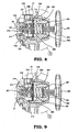
- the hanging member 33 is looped around, for example, the waist belt of a worker. Further, the housing 30 is adapted to pivot about the screw 34 (see FIG. 10 ). Hence, the device can always maintain its gravity downward even the hanging member 33 is not disposed in a vertical position.
Claims (2)
- Dispositif comprenant :un régulateur de pression (20) comprenant :un corps creux (21) comprenant une chambre de commande (210) définie à l'intérieur de ce dernier, la chambre de commande (210) ayant une voie de passage diamétrale étagée filetée (215), un couplage d'entrée (22) ayant une extrémité fixée sur le corps (21) et l'autre extrémité adaptée pour se raccorder à une bouteille sous pression portable (10) rempli avec du CO2 comprimé, un couplage de sortie (28) ayant une extrémité fixée au corps (21) et l'autre extrémité adaptée pour se raccorder à un outil pneumatique, une soupape de décharge (24) montée sur le corps (21), et une jauge de pression (27) montée sur le corps (21) ;une soupape (23) comprenant un boulon creux (230) fixé par filetage sur la section intérieurement filetée (216) de la voie de passage (215) et ayant un passage axial (234), un clapet à ressort (231) sollicité entre le creux du boulon (230) et le passage (215) et ayant un évidement axial (235), et une barre (232) ayant une extrémité installée sur l'évidement (235) et l'autre extrémité passant dans le passage (234) dans la chambre de commande (210) ;un capuchon (25) comprenant un alésage fileté à diamètre étagé (250) ayant une partie inférieure fixée par filetage au corps (21), une vis de réglage (265) fixée par filetage à une partie supérieure de l'alésage (250), et un volant de manoeuvre (266) monté sur la tête de la vis de réglage (265) ; etun ensemble d'ajustement de pression (26) disposé dans le capuchon (25) et le corps (21) et comprenant un disque d'étanchéité élastique (260) fixé dans un épaulement de l'alésage (250) sur le bord supérieur du corps (21), un disque (264) ayant un centre évidé poussé par la vis de réglage (265), un élément formant punaise (261) ayant une tige filetée, une fixation (262) pour fixer l'élément formant punaise (261) et le disque d'étanchéité (260) ensemble, et un élément de sollicitation (263) sollicité entre le disque d'étanchéité (260) et le disque (264) dans lequel le disque d'étanchéité (260) est adapté pour arrêter la communication de fluide de la chambre de commande (210) à l'alésage (250) ; dans lequel en réponse à la rotation du volant de manoeuvre (266), la vis de réglage (265) est adaptée pour pousser le disque (264) afin de comprimer l'élément de sollicitation (263) pour ajuster une première valeur de pression prédéterminée, comme représenté sur la jauge de pression (27) ; caractérisé par :un logement (30) pour enfermer partiellement le régulateur de pression (20) avec le volant de manoeuvre (266), la jauge de pression (27) et le couplage de sortie (28) étant exposés ; etun élément de suspension (33) fixé de manière pivotante sur le logement (30).
- Dispositif selon la revendication 1, dans lequel le logement (30) comprend une première coque (31) et une deuxième coque de couplage (32) fixée par filetage à la première coque (31).
Priority Applications (2)
| Application Number | Priority Date | Filing Date | Title |
|---|---|---|---|
| AT08155646T ATE520501T1 (de) | 2008-05-05 | 2008-05-05 | Tragbare vorrichtung zur versorgung eines pneumatischen werkzeuges mit komprimiertem co2 aus einem druckbehälter |
| EP08155646A EP2116332B1 (fr) | 2008-05-05 | 2008-05-05 | Dispositif portable pour alimenter un outil pneumatique en CO2 sous pression à partir d'un récipient pressurisé |
Applications Claiming Priority (1)
| Application Number | Priority Date | Filing Date | Title |
|---|---|---|---|
| EP08155646A EP2116332B1 (fr) | 2008-05-05 | 2008-05-05 | Dispositif portable pour alimenter un outil pneumatique en CO2 sous pression à partir d'un récipient pressurisé |
Publications (2)
| Publication Number | Publication Date |
|---|---|
| EP2116332A1 EP2116332A1 (fr) | 2009-11-11 |
| EP2116332B1 true EP2116332B1 (fr) | 2011-08-17 |
Family
ID=39789803
Family Applications (1)
| Application Number | Title | Priority Date | Filing Date |
|---|---|---|---|
| EP08155646A Not-in-force EP2116332B1 (fr) | 2008-05-05 | 2008-05-05 | Dispositif portable pour alimenter un outil pneumatique en CO2 sous pression à partir d'un récipient pressurisé |
Country Status (2)
| Country | Link |
|---|---|
| EP (1) | EP2116332B1 (fr) |
| AT (1) | ATE520501T1 (fr) |
Families Citing this family (11)
| Publication number | Priority date | Publication date | Assignee | Title |
|---|---|---|---|---|
| FR2976048B1 (fr) * | 2011-06-01 | 2014-05-23 | Air Liquide Medical Systems | Chapeau de protection pour robinet de reservoir de fluide sous pression |
| US9174332B2 (en) | 2012-01-06 | 2015-11-03 | Stanley Fastening Systems, L.P. | Fastening tool having an interchangeable power source |
| GB2506448A (en) * | 2012-10-01 | 2014-04-02 | Linde Ag | Sub-frame for a valve body having two or more location surfaces |
| US20160223141A1 (en) * | 2013-09-12 | 2016-08-04 | L'Air Liquide, Société Anonyme pour I'Etude et L'Exploitation des Procédés Georges Claude | Assembly comprising a protective casing and a gas cylinder with a device for indicating pressure or autonomy in the up position |
| LU92388B1 (en) * | 2014-03-03 | 2015-09-04 | Luxembourg Patent Co Sa | Cover for gas cylinder tap |
| FR3018580B1 (fr) * | 2014-03-12 | 2018-11-02 | L'air Liquide, Societe Anonyme Pour L'etude Et L'exploitation Des Procedes Georges Claude | Bloc robinet pour recipient de gaz avec dispositif indicateur de pression ou d’autonomie en position haute |
| FR3033388B1 (fr) * | 2015-03-04 | 2017-10-27 | Air Liquide | Dispositif de fourniture de fluide sous pression |
| FR3052844B1 (fr) * | 2016-06-21 | 2018-05-25 | L'air Liquide, Societe Anonyme Pour L'etude Et L'exploitation Des Procedes Georges Claude | Ensemble de distribution de gaz comprenant un capotage agence autour d'un bloc robinet equipant un recipient de gaz |
| GB201613184D0 (en) * | 2016-07-29 | 2016-09-14 | Luxfer Gas Cylinders Ltd | Improved compressed fluid vessel |
| FR3077616B1 (fr) * | 2018-02-08 | 2020-05-22 | L'air Liquide, Societe Anonyme Pour L'etude Et L'exploitation Des Procedes Georges Claude | Chapeau de protection, reservoir comprenant un tel chapeau et procede de montage |
| FR3078380B1 (fr) * | 2018-02-27 | 2020-01-31 | L'air Liquide, Societe Anonyme Pour L'etude Et L'exploitation Des Procedes Georges Claude | Capotage de protection a systeme d'accrochage pivotant pour recipient de gaz |
Family Cites Families (3)
| Publication number | Priority date | Publication date | Assignee | Title |
|---|---|---|---|---|
| FR2735209B1 (fr) * | 1995-06-08 | 1997-07-25 | Air Liquide | Ensemble robinet/detendeur pour bouteille de gaz et bouteille de gaz equipee d'un tel ensemble |
| US20050111995A1 (en) * | 2003-11-25 | 2005-05-26 | Everson Rodney W. | Carbon dioxide power system and method |
| US7325397B2 (en) | 2005-08-16 | 2008-02-05 | Chi Ping Lee | Device for continuously supplying compressed air from a portable container to a pneumatic tool by greatly reducing pressure of compressed air and then precisely adjusting same |
-
2008
- 2008-05-05 AT AT08155646T patent/ATE520501T1/de not_active IP Right Cessation
- 2008-05-05 EP EP08155646A patent/EP2116332B1/fr not_active Not-in-force
Also Published As
| Publication number | Publication date |
|---|---|
| ATE520501T1 (de) | 2011-09-15 |
| EP2116332A1 (fr) | 2009-11-11 |
Similar Documents
| Publication | Publication Date | Title |
|---|---|---|
| EP2116332B1 (fr) | Dispositif portable pour alimenter un outil pneumatique en CO2 sous pression à partir d'un récipient pressurisé | |
| US20090272443A1 (en) | Portable device for supplying compressed CO2 from a pressure vessel to a pneumatic tool | |
| US7325397B2 (en) | Device for continuously supplying compressed air from a portable container to a pneumatic tool by greatly reducing pressure of compressed air and then precisely adjusting same | |
| US6513545B2 (en) | Safety valve with adjustable maximum flow shut off mechanism | |
| US3211175A (en) | Valve regulator | |
| EP1999530B1 (fr) | Régulateur de réduction de pression à caractéristique réglable | |
| US7134447B2 (en) | Gas pressure regulator | |
| US7213734B2 (en) | Pneumatic tool drive system | |
| US5123442A (en) | Regulating shut off valve | |
| US20090078321A1 (en) | Gas pressure regulator having a regulator cap for a bayonet engagement with the regulator body | |
| US3791412A (en) | Reducing valve for high pressure fluids and connecting means therefor | |
| WO2002099322A1 (fr) | Valve de regulation de l'ecoulement d'un fluide | |
| JPH01199100A (ja) | 調整器 | |
| US20020179152A1 (en) | Regulator with improved seat | |
| US6155285A (en) | Gas safety valve | |
| CA2683022C (fr) | Orifice de soupape a ecoulement ameliore pour regulateur de pression | |
| JP5509083B2 (ja) | レギュレータ、動力供給システムおよびそれらの使用方法 | |
| US8707986B2 (en) | Pressure reducing valve | |
| CA2469418A1 (fr) | Ensemble regulateur de pression pneumatique | |
| US2501801A (en) | Combined tire inflating pressure regulator, pressure gauge, and valve device | |
| US2918082A (en) | Pressure regulating device | |
| US3243083A (en) | Containers for pressurized fluid | |
| US5158110A (en) | Device for depressing a tire valve core in high pressure cylinder | |
| US375837A (en) | scott | |
| US9746280B2 (en) | Pressure regulator for paint ball gun |
Legal Events
| Date | Code | Title | Description |
|---|---|---|---|
| PUAI | Public reference made under article 153(3) epc to a published international application that has entered the european phase |
Free format text: ORIGINAL CODE: 0009012 |
|
| AK | Designated contracting states |
Kind code of ref document: A1 Designated state(s): AT BE BG CH CY CZ DE DK EE ES FI FR GB GR HR HU IE IS IT LI LT LU LV MC MT NL NO PL PT RO SE SI SK TR |
|
| AX | Request for extension of the european patent |
Extension state: AL BA MK RS |
|
| 17P | Request for examination filed |
Effective date: 20100330 |
|
| 17Q | First examination report despatched |
Effective date: 20100429 |
|
| AKX | Designation fees paid |
Designated state(s): AT BE BG CH CY CZ DE DK EE ES FI FR GB GR HR HU IE IS IT LI LT LU LV MC MT NL NO PL PT RO SE SI SK TR |
|
| GRAP | Despatch of communication of intention to grant a patent |
Free format text: ORIGINAL CODE: EPIDOSNIGR1 |
|
| GRAC | Information related to communication of intention to grant a patent modified |
Free format text: ORIGINAL CODE: EPIDOSCIGR1 |
|
| GRAC | Information related to communication of intention to grant a patent modified |
Free format text: ORIGINAL CODE: EPIDOSCIGR1 |
|
| GRAS | Grant fee paid |
Free format text: ORIGINAL CODE: EPIDOSNIGR3 |
|
| GRAA | (expected) grant |
Free format text: ORIGINAL CODE: 0009210 |
|
| AK | Designated contracting states |
Kind code of ref document: B1 Designated state(s): AT BE BG CH CY CZ DE DK EE ES FI FR GB GR HR HU IE IS IT LI LT LU LV MC MT NL NO PL PT RO SE SI SK TR |
|
| REG | Reference to a national code |
Ref country code: GB Ref legal event code: FG4D |
|
| REG | Reference to a national code |
Ref country code: CH Ref legal event code: EP |
|
| REG | Reference to a national code |
Ref country code: IE Ref legal event code: FG4D |
|
| REG | Reference to a national code |
Ref country code: DE Ref legal event code: R096 Ref document number: 602008008883 Country of ref document: DE Effective date: 20111013 |
|
| REG | Reference to a national code |
Ref country code: NL Ref legal event code: VDEP Effective date: 20110817 |
|
| LTIE | Lt: invalidation of european patent or patent extension |
Effective date: 20110817 |
|
| PG25 | Lapsed in a contracting state [announced via postgrant information from national office to epo] |
Ref country code: SE Free format text: LAPSE BECAUSE OF FAILURE TO SUBMIT A TRANSLATION OF THE DESCRIPTION OR TO PAY THE FEE WITHIN THE PRESCRIBED TIME-LIMIT Effective date: 20110817 Ref country code: PT Free format text: LAPSE BECAUSE OF FAILURE TO SUBMIT A TRANSLATION OF THE DESCRIPTION OR TO PAY THE FEE WITHIN THE PRESCRIBED TIME-LIMIT Effective date: 20111219 Ref country code: IS Free format text: LAPSE BECAUSE OF FAILURE TO SUBMIT A TRANSLATION OF THE DESCRIPTION OR TO PAY THE FEE WITHIN THE PRESCRIBED TIME-LIMIT Effective date: 20111217 Ref country code: NL Free format text: LAPSE BECAUSE OF FAILURE TO SUBMIT A TRANSLATION OF THE DESCRIPTION OR TO PAY THE FEE WITHIN THE PRESCRIBED TIME-LIMIT Effective date: 20110817 Ref country code: NO Free format text: LAPSE BECAUSE OF FAILURE TO SUBMIT A TRANSLATION OF THE DESCRIPTION OR TO PAY THE FEE WITHIN THE PRESCRIBED TIME-LIMIT Effective date: 20111117 Ref country code: FI Free format text: LAPSE BECAUSE OF FAILURE TO SUBMIT A TRANSLATION OF THE DESCRIPTION OR TO PAY THE FEE WITHIN THE PRESCRIBED TIME-LIMIT Effective date: 20110817 Ref country code: LT Free format text: LAPSE BECAUSE OF FAILURE TO SUBMIT A TRANSLATION OF THE DESCRIPTION OR TO PAY THE FEE WITHIN THE PRESCRIBED TIME-LIMIT Effective date: 20110817 |
|
| REG | Reference to a national code |
Ref country code: AT Ref legal event code: MK05 Ref document number: 520501 Country of ref document: AT Kind code of ref document: T Effective date: 20110817 |
|
| PG25 | Lapsed in a contracting state [announced via postgrant information from national office to epo] |
Ref country code: PL Free format text: LAPSE BECAUSE OF FAILURE TO SUBMIT A TRANSLATION OF THE DESCRIPTION OR TO PAY THE FEE WITHIN THE PRESCRIBED TIME-LIMIT Effective date: 20110817 Ref country code: AT Free format text: LAPSE BECAUSE OF FAILURE TO SUBMIT A TRANSLATION OF THE DESCRIPTION OR TO PAY THE FEE WITHIN THE PRESCRIBED TIME-LIMIT Effective date: 20110817 Ref country code: GR Free format text: LAPSE BECAUSE OF FAILURE TO SUBMIT A TRANSLATION OF THE DESCRIPTION OR TO PAY THE FEE WITHIN THE PRESCRIBED TIME-LIMIT Effective date: 20111118 Ref country code: LV Free format text: LAPSE BECAUSE OF FAILURE TO SUBMIT A TRANSLATION OF THE DESCRIPTION OR TO PAY THE FEE WITHIN THE PRESCRIBED TIME-LIMIT Effective date: 20110817 Ref country code: CY Free format text: LAPSE BECAUSE OF FAILURE TO SUBMIT A TRANSLATION OF THE DESCRIPTION OR TO PAY THE FEE WITHIN THE PRESCRIBED TIME-LIMIT Effective date: 20110817 Ref country code: SI Free format text: LAPSE BECAUSE OF FAILURE TO SUBMIT A TRANSLATION OF THE DESCRIPTION OR TO PAY THE FEE WITHIN THE PRESCRIBED TIME-LIMIT Effective date: 20110817 |
|
| PG25 | Lapsed in a contracting state [announced via postgrant information from national office to epo] |
Ref country code: BE Free format text: LAPSE BECAUSE OF FAILURE TO SUBMIT A TRANSLATION OF THE DESCRIPTION OR TO PAY THE FEE WITHIN THE PRESCRIBED TIME-LIMIT Effective date: 20110817 |
|
| PG25 | Lapsed in a contracting state [announced via postgrant information from national office to epo] |
Ref country code: CZ Free format text: LAPSE BECAUSE OF FAILURE TO SUBMIT A TRANSLATION OF THE DESCRIPTION OR TO PAY THE FEE WITHIN THE PRESCRIBED TIME-LIMIT Effective date: 20110817 Ref country code: SK Free format text: LAPSE BECAUSE OF FAILURE TO SUBMIT A TRANSLATION OF THE DESCRIPTION OR TO PAY THE FEE WITHIN THE PRESCRIBED TIME-LIMIT Effective date: 20110817 |
|
| PG25 | Lapsed in a contracting state [announced via postgrant information from national office to epo] |
Ref country code: EE Free format text: LAPSE BECAUSE OF FAILURE TO SUBMIT A TRANSLATION OF THE DESCRIPTION OR TO PAY THE FEE WITHIN THE PRESCRIBED TIME-LIMIT Effective date: 20110817 Ref country code: RO Free format text: LAPSE BECAUSE OF FAILURE TO SUBMIT A TRANSLATION OF THE DESCRIPTION OR TO PAY THE FEE WITHIN THE PRESCRIBED TIME-LIMIT Effective date: 20110817 Ref country code: IT Free format text: LAPSE BECAUSE OF FAILURE TO SUBMIT A TRANSLATION OF THE DESCRIPTION OR TO PAY THE FEE WITHIN THE PRESCRIBED TIME-LIMIT Effective date: 20110817 |
|
| PLBE | No opposition filed within time limit |
Free format text: ORIGINAL CODE: 0009261 |
|
| STAA | Information on the status of an ep patent application or granted ep patent |
Free format text: STATUS: NO OPPOSITION FILED WITHIN TIME LIMIT |
|
| PG25 | Lapsed in a contracting state [announced via postgrant information from national office to epo] |
Ref country code: DK Free format text: LAPSE BECAUSE OF FAILURE TO SUBMIT A TRANSLATION OF THE DESCRIPTION OR TO PAY THE FEE WITHIN THE PRESCRIBED TIME-LIMIT Effective date: 20110817 |
|
| 26N | No opposition filed |
Effective date: 20120521 |
|
| PG25 | Lapsed in a contracting state [announced via postgrant information from national office to epo] |
Ref country code: HR Free format text: LAPSE BECAUSE OF FAILURE TO SUBMIT A TRANSLATION OF THE DESCRIPTION OR TO PAY THE FEE WITHIN THE PRESCRIBED TIME-LIMIT Effective date: 20120321 |
|
| REG | Reference to a national code |
Ref country code: DE Ref legal event code: R097 Ref document number: 602008008883 Country of ref document: DE Effective date: 20120521 |
|
| PG25 | Lapsed in a contracting state [announced via postgrant information from national office to epo] |
Ref country code: MC Free format text: LAPSE BECAUSE OF NON-PAYMENT OF DUE FEES Effective date: 20120531 |
|
| REG | Reference to a national code |
Ref country code: CH Ref legal event code: PL |
|
| PG25 | Lapsed in a contracting state [announced via postgrant information from national office to epo] |
Ref country code: CH Free format text: LAPSE BECAUSE OF NON-PAYMENT OF DUE FEES Effective date: 20120531 Ref country code: LI Free format text: LAPSE BECAUSE OF NON-PAYMENT OF DUE FEES Effective date: 20120531 |
|
| REG | Reference to a national code |
Ref country code: IE Ref legal event code: MM4A |
|
| PG25 | Lapsed in a contracting state [announced via postgrant information from national office to epo] |
Ref country code: ES Free format text: LAPSE BECAUSE OF FAILURE TO SUBMIT A TRANSLATION OF THE DESCRIPTION OR TO PAY THE FEE WITHIN THE PRESCRIBED TIME-LIMIT Effective date: 20111128 Ref country code: IE Free format text: LAPSE BECAUSE OF NON-PAYMENT OF DUE FEES Effective date: 20120505 |
|
| PG25 | Lapsed in a contracting state [announced via postgrant information from national office to epo] |
Ref country code: BG Free format text: LAPSE BECAUSE OF FAILURE TO SUBMIT A TRANSLATION OF THE DESCRIPTION OR TO PAY THE FEE WITHIN THE PRESCRIBED TIME-LIMIT Effective date: 20111117 |
|
| PG25 | Lapsed in a contracting state [announced via postgrant information from national office to epo] |
Ref country code: MT Free format text: LAPSE BECAUSE OF FAILURE TO SUBMIT A TRANSLATION OF THE DESCRIPTION OR TO PAY THE FEE WITHIN THE PRESCRIBED TIME-LIMIT Effective date: 20110817 |
|
| PG25 | Lapsed in a contracting state [announced via postgrant information from national office to epo] |
Ref country code: HR Free format text: LAPSE BECAUSE OF FAILURE TO SUBMIT A TRANSLATION OF THE DESCRIPTION OR TO PAY THE FEE WITHIN THE PRESCRIBED TIME-LIMIT Effective date: 20110817 |
|
| PG25 | Lapsed in a contracting state [announced via postgrant information from national office to epo] |
Ref country code: TR Free format text: LAPSE BECAUSE OF FAILURE TO SUBMIT A TRANSLATION OF THE DESCRIPTION OR TO PAY THE FEE WITHIN THE PRESCRIBED TIME-LIMIT Effective date: 20110817 |
|
| PG25 | Lapsed in a contracting state [announced via postgrant information from national office to epo] |
Ref country code: LU Free format text: LAPSE BECAUSE OF NON-PAYMENT OF DUE FEES Effective date: 20120505 |
|
| PG25 | Lapsed in a contracting state [announced via postgrant information from national office to epo] |
Ref country code: HU Free format text: LAPSE BECAUSE OF FAILURE TO SUBMIT A TRANSLATION OF THE DESCRIPTION OR TO PAY THE FEE WITHIN THE PRESCRIBED TIME-LIMIT Effective date: 20080505 |
|
| PGFP | Annual fee paid to national office [announced via postgrant information from national office to epo] |
Ref country code: GB Payment date: 20140521 Year of fee payment: 7 |
|
| PGFP | Annual fee paid to national office [announced via postgrant information from national office to epo] |
Ref country code: FR Payment date: 20140507 Year of fee payment: 7 Ref country code: DE Payment date: 20140528 Year of fee payment: 7 |
|
| REG | Reference to a national code |
Ref country code: DE Ref legal event code: R119 Ref document number: 602008008883 Country of ref document: DE |
|
| GBPC | Gb: european patent ceased through non-payment of renewal fee |
Effective date: 20150505 |
|
| REG | Reference to a national code |
Ref country code: FR Ref legal event code: ST Effective date: 20160129 |
|
| PG25 | Lapsed in a contracting state [announced via postgrant information from national office to epo] |
Ref country code: GB Free format text: LAPSE BECAUSE OF NON-PAYMENT OF DUE FEES Effective date: 20150505 Ref country code: DE Free format text: LAPSE BECAUSE OF NON-PAYMENT OF DUE FEES Effective date: 20151201 |
|
| PG25 | Lapsed in a contracting state [announced via postgrant information from national office to epo] |
Ref country code: FR Free format text: LAPSE BECAUSE OF NON-PAYMENT OF DUE FEES Effective date: 20150601 |