EP2116158A2 - Food cooking device (variants) - Google Patents
Food cooking device (variants) Download PDFInfo
- Publication number
- EP2116158A2 EP2116158A2 EP08724070A EP08724070A EP2116158A2 EP 2116158 A2 EP2116158 A2 EP 2116158A2 EP 08724070 A EP08724070 A EP 08724070A EP 08724070 A EP08724070 A EP 08724070A EP 2116158 A2 EP2116158 A2 EP 2116158A2
- Authority
- EP
- European Patent Office
- Prior art keywords
- electric
- plug
- socket
- vessel
- main body
- Prior art date
- Legal status (The legal status is an assumption and is not a legal conclusion. Google has not performed a legal analysis and makes no representation as to the accuracy of the status listed.)
- Granted
Links
Images


Classifications
-
- A—HUMAN NECESSITIES
- A47—FURNITURE; DOMESTIC ARTICLES OR APPLIANCES; COFFEE MILLS; SPICE MILLS; SUCTION CLEANERS IN GENERAL
- A47J—KITCHEN EQUIPMENT; COFFEE MILLS; SPICE MILLS; APPARATUS FOR MAKING BEVERAGES
- A47J27/00—Cooking-vessels
- A47J27/004—Cooking-vessels with integral electrical heating means
-
- A—HUMAN NECESSITIES
- A47—FURNITURE; DOMESTIC ARTICLES OR APPLIANCES; COFFEE MILLS; SPICE MILLS; SUCTION CLEANERS IN GENERAL
- A47J—KITCHEN EQUIPMENT; COFFEE MILLS; SPICE MILLS; APPARATUS FOR MAKING BEVERAGES
- A47J27/00—Cooking-vessels
- A47J27/21—Water-boiling vessels, e.g. kettles
- A47J27/21008—Water-boiling vessels, e.g. kettles electrically heated
- A47J27/2105—Water-boiling vessels, e.g. kettles electrically heated of the cordless type, i.e. whereby the water vessel can be plugged into an electrically-powered base element
-
- A—HUMAN NECESSITIES
- A47—FURNITURE; DOMESTIC ARTICLES OR APPLIANCES; COFFEE MILLS; SPICE MILLS; SUCTION CLEANERS IN GENERAL
- A47J—KITCHEN EQUIPMENT; COFFEE MILLS; SPICE MILLS; APPARATUS FOR MAKING BEVERAGES
- A47J36/00—Parts, details or accessories of cooking-vessels
- A47J36/32—Time-controlled igniting mechanisms or alarm devices
- A47J36/321—Time-controlled igniting mechanisms or alarm devices the electronic control being performed over a network, e.g. by means of a handheld device
Definitions
- the inventions relate to the field of fulfilling human living requirements, and specifically to a household electric appliance, and are intended for the heat treatment of food products and water.
- An electric saucepan is known [ EP 1115316 , WO 9920163 , Int. CI. A47J27/00. Maravic Dusko (CH)], said saucepan comprising an electrically heatable vessel with a heat source integrated in the base thereof.
- An electrically insulating layer, electrical resistance layer and heat-insulating layer are applied to the external side of the vessel base. Heat which can be generated outside the vessel penetrates the interior thereof through the base thereof.
- a shortcoming of said device is the absence of an external body which protects a person from burns and furniture from damage, and also the absence of an option for controlling and regulating the food treatment time and temperature.
- a cordless electric kettle is known and selected as the prior art [ RF patent No. 2287213 , Int. Cl. H01R33 / 20 (January 2006), A47J27 / 082 (January 2006), published October 11, 2006], said kettle having a main body with a water-carrying vessel, and a heating element, heat-sensitive switch, and a base which, during use, is connected to an electric power source by an electric plug and socket unit which has a plug part provided on the main body or on the base and a socket part of the plug and socket unit either on the main body or on the base in order to provide an electrical connection therebetween in any relative rotational orientation about a vertical axis.
- That part of the plug and socket unit which is on the main body is supported on part of the body of the electric heating element.
- Electric conductors connect the part of the plug and socket unit on the main body to the heating element and/or to the heat-sensitive switch and are permanently fastened to the abovementioned part of the plug and socket unit on the main body.
- Part of a shell for enclosing the lower area of the water-containing vessel, heating element and heat-sensitive switch is supported on the abovementioned part of the plug and socket unit. The heating element and heat-sensitive switch are fastened to the lower area of the water-containing vessel.
- Said device is not provided with an external body which protects a person from burns.
- the shell only encloses the lower part of the vessel. There is no option for program control as a function of the type of food being prepared.
- a device for the heat treatment of products as per the first variant, as in the prior art comprises a main body with a vessel which is equipped in the lower part thereof with a heating element and a thermal fuse, and a base which can be connected during use to an electric power source, wherein the central, upper part of the base is provided with a socket part of an electric plug and socket unit, and the bottom of the main body is provided with a plug part of the electric plug and socket unit.
- the vessel which is hermetically connected to the upper part of the body via a heat-resistant sealing ring, is arranged with a clearance within the main body.
- a heat-reflecting screen is placed with a clearance between the bottom of the vessel and bottom of the body.
- the thermal fuse and a temperature sensor are connected to the heating device and, in turn, are connected to the plug part of the electric plug and socket unit.
- a power supply and control module is used as the base, said module comprising a control unit which is connected to a keyboard, a display, a dynamic loudspeaker, a pressure sensor, the socket part of the electric plug and socket unit, an electric power source, and a transceiver, with the option of being connected by means of either a radiocommunication or infrared communication to a transceiver of a remote control device.
- An electric contact of a remote control console has the option of being connected to an electric contact of a recharging module of the remote control console, which recharging module is attached to the electric power source.
- the remote control device comprises a control unit which is connected to the transceiver, keyboard, display and storage battery thereof, and an electric contact, which has the option of being connected to the electric contact of the recharging module of the remote control console, is attached to said storage battery, the transceiver having the option either of a radiocommunication or infrared communication with the transceiver of the power supply and control module.
- the recharging module of the remote control device comprises a voltage converter which is attached to the electric power source, the voltage converter being connected to an electric contact which communicates with an electric contact of a remote control console.
- a device for the heat treatment of products as per the second variant, as in the prior art, comprises a main body with a vessel which is equipped in the lower part thereof with a heating element and a thermal fuse, wherein the body has the option of being connected to an electric power source via a plug part of an electric plug and socket unit.
- a vessel which is hermetically connected to an upper part of the body via a heat-resistant sealing ring, is arranged with a clearance within the main body.
- a heat-reflecting screen is placed with a clearance between the bottom of the vessel and bottom of the body.
- the thermal fuse and a temperature sensor are connected to a heating device and, in turn, are connected to the plug part of the electric plug and socket unit, which part is constructed in a lateral surface of the body.
- Said plug part of the electric plug and socket unit has the option of being connected to a socket part of an electric lead, the plug part of which has the option of being connected to the socket part of the electric plug and socket unit of the power supply and control module, said module comprising a control unit which is connected to a keyboard, a display, a dynamic loudspeaker, the socket part of the electric plug and socket unit, and an electric power source.
- the main body of the variants of said devices can be in the form either of a saucepan, or a frying pan, or a kettle.
- the technical solutions proposed provide control of the heating element and make it possible to automate the food preparation process: to establish the required temperature and time and to use various combinations thereof, with storage thereof in a memory, and also to measure the weight of the dish and calculate the amount of calories.
- a set of necessary commands is made possible with the aid of the keyboard.
- the display depicts the current food preparation parameters.
- the external - main-body of the proposed devices protects a person from burns and the surface of furniture from damage, since it does not heat up to a high temperature. Furthermore, the external body carries out the function of a Thermos, and thus keeps food warm for a long time and ensures a saving on electric energy.
- the hermetic nature of the connection between the external body and internal vessel and absence of leads make it possible to easily wash the utensils after the preparation of food, including washing them in a dishwasher.
- the presence of the heat-reflecting screen which is arranged with a clearance between the bottom of the heatable vessel and the bottom of the body reduces heat losses, which increases the heating speed and provides a saving on electric energy.
- the electrical connection between the base and main body is ensured in any relative rotational orientation about the vertical axis.
- the remote control device makes it possible to control the food preparation process remotely.
- Said device can be integrated into an "intelligent home” system and can be controlled using a cellphone or also via the Internet.
- saucepans a frying pan and kettle in one kit ensures the multifunctional nature of the device and the option of cooking, frying, stewing, boiling, heating up etc.
- the device for the heat treatment of products according to the first variant comprises a body 1 ( fig. 1 ) in the form of a saucepan, frying pan or kettle which can be placed on a separate base comprising a power supply and control module 2.
- a connection therebetween is provided by an electric plug and socket unit.
- the upper surface of the base is provided with the socket part 3 of the electric plug and socket unit while the plug part 4 is in the central part of the bottom of the body 1.
- a vessel 5 of smaller volume is arranged with a clearance (either filled with air or a heat insulator) within the body 1 and is hermetically connected thereto at the top via a heat-resistant sealing ring 6.
- the inner side of the vessel 5 can be covered with an anti-stick layer.
- the external side of the bottom of the vessel 5 is equipped with a heating element 7 comprising either a heat-conducting device fastened to the external side of the bottom of the vessel 5 or a covering based on film-type heating elements, said covering being applied directly to the external side of the bottom of the vessel 5.
- a thermal fuse 8 and temperature sensor 9 are connected to the heating element 7 and, in turn, are connected to the plug part 4 of the electric plug and socket unit.
- a heat-reflecting screen 10 is arranged with a clearance between the bottom of the vessel 5 and bottom of the body 1.
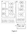
- the power supply and control module 2 ( fig. 3 ) comprises a first control unit 11 which is electrically connected to a first keyboard 12, first display 13, dynamic loudspeaker 14, pressure sensor 15, transceiver 16, socket part 3 of the electric plug and socket unit and, by an electric lead, to the electric power source.
- the remote control device 17 comprises a second transceiver 18 connected to a second control unit 19 to which a second keyboard 20, second display 21 and storage battery 22 are connected, said storage battery being connected via a first electric contact 23 to a second electric contact 24 of a recharging module of the remote control device 25.
- the second electric contact 24 is connected to a voltage converter 26 which is attached to the electric power source.
- the body 1 ( fig. 4 ) is connected to the power supply and control module 2 by means of an electric cord 27 and electric plug and socket units arranged thereon.
- the socket part 28 of the first electric plug and socket unit is arranged on one side of the electric cord 27 while the plug part 29 of the first electric plug and socket unit is constructed in a lateral surface of the body 1.
- the plug part 30 of the second electric plug and socket unit is arranged on the other side of the electric cord 27 while the socket part 31 of the second electric plug and socket unit is constructed on a lateral surface of the power supply and control module 2.
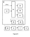
- the thermal fuse 8 and temperature sensor 9 are connected to the heating element 7 and, in turn, are connected to the plug part 29 of the first electric plug and socket unit ( fig. 5 ).
- the power supply and control module 2 comprises a control unit 11 which is electrically connected to a keyboard 12, display 13, dynamic loudspeaker 14, and to an electric power source, and, via a socket part 31, to the plug part 30 of the second electric plug and socket unit.
- the device for the heat treatment of products according to the first variant operates as follows.
- the voltage is converted and fed to the first keyboard 12, pressure sensor 15, first display 13, dynamic loudspeaker 14 and first transceiver 16.
- a closed contact between the socket part 3 and plug part 4 of the electric plug and socket unit ensures the mechanical connection thereof when the body 1 is placed onto the power supply and control module 2.
- Corresponding commands concerning the operating modes of the device are issued with the aid of the first keyboard 12 and enter the input of the first control unit 11.
- Signals from the pressure sensor 15 also enter the first control unit 11.
- the first control unit 11 converts the signals from the first keyboard 12 and signals from the pressure sensor 15 into digital codes and transmits the result to the first display 13, and also generates a signal which is transmitted to the dynamic loudspeaker 14.
- the first control unit 11 also feeds the voltage to the socket part 3 of the electric plug and socket unit which transmits the voltage via the plug part 4 of the electric plug and socket unit and thermal fuse 8 to the heating element 7.
- the temperature sensor 9 records the changes in temperature, generates an analogous signal and transmits the latter to the input of the first control unit 11 via the electric plug and socket unit.
- the first control unit 11 converts the analogous voltage value into digital code and transmits the latter to the first display 13, and also generates a signal which controls the supply of voltage to the heating device 7. All of the digital signals transmitted by the first control unit 11 to the first display 13 are converted into a frequency signal and transmitted to the first transceiver 16.
- a remote control device 17 operates by simultaneously fulfilling the following conditions: by supplying voltage from the storage battery 22 to the second control unit 19 and by supplying a signal concerning the switching on of the remote control device 17 from the second keyboard 20 to the second control unit 19. This can be realized in the following manner.
- Voltage from the output of the storage battery 22 enters the input of the second control unit 19.
- Voltage from the output of the second control unit 19 enters the second keyboard 20 and second display 21.
- a signal concerning the switching on of the remote control device 17 passes from the output of the second keyboard 20 to the input of the second control unit 19, said signal closing an electric switch in the second control unit 19 and feeding voltage from the output thereof to the input of the second transceiver 18.
- a voltage converter 26 which transmits the power voltage via the first electric contact 23 and second electric contact 24, which form a closed loop, and charges the storage battery 22.
- Signals concerning corresponding commands pass from the second keyboard 20 to the second control unit 19, the latter converting said signals into digital codes and transmitting them to the second display 21, and also generating a signal and transmitting the latter to the input of the second transceiver 18.
- the interaction of the power supply and control module 2 with the remote control device 17 ensures an exchange of signals between the first transceiver 16 and second transceiver 18. Signals are transmitted from the output of the first transceiver 16 to the input of the second transceiver 18, the second transceiver 18 transmitting said signals to the second control unit 19.
- the second control unit 19 converts the signals into digital codes and transmits the latter to the input of the second display 21. Signals are transmitted from the output of the second transceiver 18 to the input of the first transceiver 16, the first transceiver 16 transmitting said signals to the first control unit 11.
- the first control unit 11 converts the signals into digital codes, transmits them to the first display 13 and generates corresponding control signals.
- the device for the heat treatment of products according to the second variant operates as follows.
- Corresponding commands concerning the operating modes of the device are issued with the aid of the keyboard 12 and enter the input of the control unit 11.
- the control unit 11 converts the signals into digital codes and transmits the result to the display 13 and also generates a signal which is transmitted to the dynamic loudspeaker 14.
- the control unit also feeds voltage to the heating element 7 via the electric plug and socket units and thermal fuse 8.
- the temperature sensor 9 records the change in temperature of the heating device 7, generates an analogous signal and transmits the latter to the input of the control unit 11 via electric plug and socket units.
- the control unit 11 converts an analogous voltage value into digital code and transmits the latter to the display 13, and also generates signals of corresponding control commands and a signal which controls the feeding of voltage to the heating element 7.
- the vessel 5 can be manufactured from stainless steel, the external body 1 of the device from thermoplastic, and the heat-reflecting screen 10 from aluminum.
- the socket part 3 and plug part 4 of the electric plug and socket unit can be realized using electric plug and socket units R72A and R72C (STRIX), and the socket parts 28, 31 and plug parts 29, 30 of the first and second electric plug and socket units can be realized using electric plug and socket units AC101 and AC102.
- Film-type heaters for example technical specification U29.7-23501650-002-2003
- tubular heating elements can be used as the heating element 7.
- the thermal fuse 8 can be realized using TZD 270 and the temperature sensor 9 using TS 0295/1; TP 0188/1.
- a first control unit 11 and second control unit 19 can be realized using microcircuits ATmega 16-16A1, the first display 13 and second display 21 using the indicator OSD20400M01, the dynamic loudspeaker 14 using the sound emitter EFM-250D (EAST), the pressure sensor 15 using the microcircuit MS54XX, and the first transceiver 16 and second transceiver 18 using AT86RF21 1 S (Atmel).
- the storage battery 22 can be realized using an Ni-MH battery, 750 mAh (Panasonic).
- the first electric contact 23 and second electric contact 24 are made of current-conducting metal.
- a transformer BVEI 303 2030 1 BA/6B (HAHN) can be selected as the voltage converter 26. Any electronic device combined with a control unit 11 with a communication channel (for example radio channel of a mobile telephone, wire communication, etc.) can be selected as the remote control device 17.
Abstract
Description
- The inventions relate to the field of fulfilling human living requirements, and specifically to a household electric appliance, and are intended for the heat treatment of food products and water.
- An electric saucepan is known [
EP 1115316 ,WO 9920163 - A shortcoming of said device is the absence of an external body which protects a person from burns and furniture from damage, and also the absence of an option for controlling and regulating the food treatment time and temperature.
- A cordless electric kettle is known and selected as the prior art [
RF patent No. 2287213 , Int. Cl. H01R33/20 (January 2006), A47J27/082 (January 2006), published October 11, 2006], said kettle having a main body with a water-carrying vessel, and a heating element, heat-sensitive switch, and a base which, during use, is connected to an electric power source by an electric plug and socket unit which has a plug part provided on the main body or on the base and a socket part of the plug and socket unit either on the main body or on the base in order to provide an electrical connection therebetween in any relative rotational orientation about a vertical axis. That part of the plug and socket unit which is on the main body is supported on part of the body of the electric heating element. Electric conductors connect the part of the plug and socket unit on the main body to the heating element and/or to the heat-sensitive switch and are permanently fastened to the abovementioned part of the plug and socket unit on the main body. Part of a shell for enclosing the lower area of the water-containing vessel, heating element and heat-sensitive switch is supported on the abovementioned part of the plug and socket unit. The heating element and heat-sensitive switch are fastened to the lower area of the water-containing vessel. - Said device is not provided with an external body which protects a person from burns. The shell only encloses the lower part of the vessel. There is no option for program control as a function of the type of food being prepared.
- It is the object of the inventions to expand the range of devices of analogous purpose.
- The object set is achieved in that a device for the heat treatment of products as per the first variant, as in the prior art, comprises a main body with a vessel which is equipped in the lower part thereof with a heating element and a thermal fuse, and a base which can be connected during use to an electric power source, wherein the central, upper part of the base is provided with a socket part of an electric plug and socket unit, and the bottom of the main body is provided with a plug part of the electric plug and socket unit.
- According to the invention, the vessel, which is hermetically connected to the upper part of the body via a heat-resistant sealing ring, is arranged with a clearance within the main body. A heat-reflecting screen is placed with a clearance between the bottom of the vessel and bottom of the body. The thermal fuse and a temperature sensor are connected to the heating device and, in turn, are connected to the plug part of the electric plug and socket unit. A power supply and control module is used as the base, said module comprising a control unit which is connected to a keyboard, a display, a dynamic loudspeaker, a pressure sensor, the socket part of the electric plug and socket unit, an electric power source, and a transceiver, with the option of being connected by means of either a radiocommunication or infrared communication to a transceiver of a remote control device. An electric contact of a remote control console has the option of being connected to an electric contact of a recharging module of the remote control console, which recharging module is attached to the electric power source.
- The remote control device comprises a control unit which is connected to the transceiver, keyboard, display and storage battery thereof, and an electric contact, which has the option of being connected to the electric contact of the recharging module of the remote control console, is attached to said storage battery, the transceiver having the option either of a radiocommunication or infrared communication with the transceiver of the power supply and control module.
- The recharging module of the remote control device comprises a voltage converter which is attached to the electric power source, the voltage converter being connected to an electric contact which communicates with an electric contact of a remote control console.
- A device for the heat treatment of products as per the second variant, as in the prior art, comprises a main body with a vessel which is equipped in the lower part thereof with a heating element and a thermal fuse, wherein the body has the option of being connected to an electric power source via a plug part of an electric plug and socket unit.
- According to the invention, a vessel, which is hermetically connected to an upper part of the body via a heat-resistant sealing ring, is arranged with a clearance within the main body. A heat-reflecting screen is placed with a clearance between the bottom of the vessel and bottom of the body. The thermal fuse and a temperature sensor are connected to a heating device and, in turn, are connected to the plug part of the electric plug and socket unit, which part is constructed in a lateral surface of the body. Said plug part of the electric plug and socket unit has the option of being connected to a socket part of an electric lead, the plug part of which has the option of being connected to the socket part of the electric plug and socket unit of the power supply and control module, said module comprising a control unit which is connected to a keyboard, a display, a dynamic loudspeaker, the socket part of the electric plug and socket unit, and an electric power source.
- The main body of the variants of said devices can be in the form either of a saucepan, or a frying pan, or a kettle.
- The technical solutions proposed provide control of the heating element and make it possible to automate the food preparation process: to establish the required temperature and time and to use various combinations thereof, with storage thereof in a memory, and also to measure the weight of the dish and calculate the amount of calories. A set of necessary commands is made possible with the aid of the keyboard. The display depicts the current food preparation parameters. When the installed program or combinations thereof is or are completed, the device is automatically switched off, accompanied by a corresponding audible signal.
- The external - main-body of the proposed devices protects a person from burns and the surface of furniture from damage, since it does not heat up to a high temperature. Furthermore, the external body carries out the function of a Thermos, and thus keeps food warm for a long time and ensures a saving on electric energy. The hermetic nature of the connection between the external body and internal vessel and absence of leads make it possible to easily wash the utensils after the preparation of food, including washing them in a dishwasher.
- The presence of the heat-reflecting screen which is arranged with a clearance between the bottom of the heatable vessel and the bottom of the body reduces heat losses, which increases the heating speed and provides a saving on electric energy.
- In the device according to the first variant, the electrical connection between the base and main body is ensured in any relative rotational orientation about the vertical axis. The remote control device makes it possible to control the food preparation process remotely. Said device can be integrated into an "intelligent home" system and can be controlled using a cellphone or also via the Internet.
- The provision of saucepans, a frying pan and kettle in one kit ensures the multifunctional nature of the device and the option of cooking, frying, stewing, boiling, heating up etc.
-
-
Figure 1 depicts a general view of the first variant of the device for the heat treatment of products and water (without a remote control device); -
Figure 2 shows the remote control device, in a view from the front and side; -
Figure 3 depicts an equipment diagram for the first variant of the device; -
Figure 4 depicts a general view of the second variant of the device; and -
Figure 5 depicts an equipment part of the second variant of the device. - The device for the heat treatment of products according to the first variant comprises a body 1 (
fig. 1 ) in the form of a saucepan, frying pan or kettle which can be placed on a separate base comprising a power supply andcontrol module 2. A connection therebetween is provided by an electric plug and socket unit. The upper surface of the base is provided with thesocket part 3 of the electric plug and socket unit while the plug part 4 is in the central part of the bottom of the body 1. - A vessel 5 of smaller volume is arranged with a clearance (either filled with air or a heat insulator) within the body 1 and is hermetically connected thereto at the top via a heat-resistant sealing ring 6. The inner side of the vessel 5 can be covered with an anti-stick layer.
- The external side of the bottom of the vessel 5 is equipped with a heating element 7 comprising either a heat-conducting device fastened to the external side of the bottom of the vessel 5 or a covering based on film-type heating elements, said covering being applied directly to the external side of the bottom of the vessel 5. A
thermal fuse 8 andtemperature sensor 9 are connected to the heating element 7 and, in turn, are connected to the plug part 4 of the electric plug and socket unit. - A heat-reflecting screen 10 is arranged with a clearance between the bottom of the vessel 5 and bottom of the body 1.
- The power supply and control module 2 (
fig. 3 ) comprises afirst control unit 11 which is electrically connected to afirst keyboard 12,first display 13,dynamic loudspeaker 14,pressure sensor 15,transceiver 16,socket part 3 of the electric plug and socket unit and, by an electric lead, to the electric power source. - The
remote control device 17 comprises asecond transceiver 18 connected to asecond control unit 19 to which asecond keyboard 20,second display 21 andstorage battery 22 are connected, said storage battery being connected via a firstelectric contact 23 to a secondelectric contact 24 of a recharging module of theremote control device 25. The secondelectric contact 24 is connected to avoltage converter 26 which is attached to the electric power source. - In the second variant of the device for the heat treatment of products, the body 1 (
fig. 4 ) is connected to the power supply andcontrol module 2 by means of an electric cord 27 and electric plug and socket units arranged thereon. Thesocket part 28 of the first electric plug and socket unit is arranged on one side of the electric cord 27 while theplug part 29 of the first electric plug and socket unit is constructed in a lateral surface of the body 1. Theplug part 30 of the second electric plug and socket unit is arranged on the other side of the electric cord 27 while thesocket part 31 of the second electric plug and socket unit is constructed on a lateral surface of the power supply andcontrol module 2. - The
thermal fuse 8 andtemperature sensor 9 are connected to the heating element 7 and, in turn, are connected to theplug part 29 of the first electric plug and socket unit (fig. 5 ). - The power supply and
control module 2 comprises acontrol unit 11 which is electrically connected to akeyboard 12,display 13,dynamic loudspeaker 14, and to an electric power source, and, via asocket part 31, to theplug part 30 of the second electric plug and socket unit. - The device for the heat treatment of products according to the first variant operates as follows.
- When electric power is supplied to the
first control unit 11, the voltage is converted and fed to thefirst keyboard 12,pressure sensor 15,first display 13,dynamic loudspeaker 14 andfirst transceiver 16. A closed contact between thesocket part 3 and plug part 4 of the electric plug and socket unit ensures the mechanical connection thereof when the body 1 is placed onto the power supply andcontrol module 2. - Corresponding commands concerning the operating modes of the device (temperature and heating time, number and name of the program, measuring of the weight, calculation of calories, etc.) are issued with the aid of the
first keyboard 12 and enter the input of thefirst control unit 11. Signals from thepressure sensor 15 also enter thefirst control unit 11. Thefirst control unit 11 converts the signals from thefirst keyboard 12 and signals from thepressure sensor 15 into digital codes and transmits the result to thefirst display 13, and also generates a signal which is transmitted to thedynamic loudspeaker 14. Thefirst control unit 11 also feeds the voltage to thesocket part 3 of the electric plug and socket unit which transmits the voltage via the plug part 4 of the electric plug and socket unit andthermal fuse 8 to the heating element 7. Thetemperature sensor 9 records the changes in temperature, generates an analogous signal and transmits the latter to the input of thefirst control unit 11 via the electric plug and socket unit. Thefirst control unit 11 converts the analogous voltage value into digital code and transmits the latter to thefirst display 13, and also generates a signal which controls the supply of voltage to the heating device 7. All of the digital signals transmitted by thefirst control unit 11 to thefirst display 13 are converted into a frequency signal and transmitted to thefirst transceiver 16. - A
remote control device 17 operates by simultaneously fulfilling the following conditions: by supplying voltage from thestorage battery 22 to thesecond control unit 19 and by supplying a signal concerning the switching on of theremote control device 17 from thesecond keyboard 20 to thesecond control unit 19. This can be realized in the following manner. - Voltage from the output of the
storage battery 22 enters the input of thesecond control unit 19. Voltage from the output of thesecond control unit 19 enters thesecond keyboard 20 andsecond display 21. A signal concerning the switching on of theremote control device 17 passes from the output of thesecond keyboard 20 to the input of thesecond control unit 19, said signal closing an electric switch in thesecond control unit 19 and feeding voltage from the output thereof to the input of thesecond transceiver 18. - In order to charge up the
storage battery 22, use is made of avoltage converter 26 which transmits the power voltage via the firstelectric contact 23 and secondelectric contact 24, which form a closed loop, and charges thestorage battery 22. - Signals concerning corresponding commands pass from the
second keyboard 20 to thesecond control unit 19, the latter converting said signals into digital codes and transmitting them to thesecond display 21, and also generating a signal and transmitting the latter to the input of thesecond transceiver 18. - The interaction of the power supply and
control module 2 with theremote control device 17 ensures an exchange of signals between thefirst transceiver 16 andsecond transceiver 18. Signals are transmitted from the output of thefirst transceiver 16 to the input of thesecond transceiver 18, thesecond transceiver 18 transmitting said signals to thesecond control unit 19. Thesecond control unit 19 converts the signals into digital codes and transmits the latter to the input of thesecond display 21. Signals are transmitted from the output of thesecond transceiver 18 to the input of thefirst transceiver 16, thefirst transceiver 16 transmitting said signals to thefirst control unit 11. Thefirst control unit 11 converts the signals into digital codes, transmits them to thefirst display 13 and generates corresponding control signals. - The device for the heat treatment of products according to the second variant operates as follows.
- When electric power is fed to the
control unit 11, voltage is converted and is fed to thekeyboard 12,display 13 anddynamic loudspeaker 14. The closed contact between thesocket part 28 and plugpart 29 of the first electric plug and socket unit, and also between theplug part 30 andsocket part 31 of the second electric plug and socket unit ensures the mechanical connection thereof. - Corresponding commands concerning the operating modes of the device (temperature and heating time, number of program combinations, number and name of the program, calculation of calories, etc.) are issued with the aid of the
keyboard 12 and enter the input of thecontrol unit 11. Thecontrol unit 11 converts the signals into digital codes and transmits the result to thedisplay 13 and also generates a signal which is transmitted to thedynamic loudspeaker 14. The control unit also feeds voltage to the heating element 7 via the electric plug and socket units andthermal fuse 8. Thetemperature sensor 9 records the change in temperature of the heating device 7, generates an analogous signal and transmits the latter to the input of thecontrol unit 11 via electric plug and socket units. Thecontrol unit 11 converts an analogous voltage value into digital code and transmits the latter to thedisplay 13, and also generates signals of corresponding control commands and a signal which controls the feeding of voltage to the heating element 7. - The vessel 5 can be manufactured from stainless steel, the external body 1 of the device from thermoplastic, and the heat-reflecting screen 10 from aluminum. The
socket part 3 and plug part 4 of the electric plug and socket unit can be realized using electric plug and socket units R72A and R72C (STRIX), and thesocket parts parts thermal fuse 8 can be realized using TZD 270 and thetemperature sensor 9 using TS 0295/1; TP 0188/1. Afirst control unit 11 andsecond control unit 19 can be realized using microcircuits ATmega 16-16A1, thefirst display 13 andsecond display 21 using the indicator OSD20400M01, thedynamic loudspeaker 14 using the sound emitter EFM-250D (EAST), thepressure sensor 15 using the microcircuit MS54XX, and thefirst transceiver 16 andsecond transceiver 18 using AT86RF21 1 S (Atmel). Thestorage battery 22 can be realized using an Ni-MH battery, 750 mAh (Panasonic). The firstelectric contact 23 and secondelectric contact 24 are made of current-conducting metal. A transformer BVEI 303 2030 1 BA/6B (HAHN) can be selected as thevoltage converter 26. Any electronic device combined with acontrol unit 11 with a communication channel (for example radio channel of a mobile telephone, wire communication, etc.) can be selected as theremote control device 17.
Claims (6)
- A device for the heat treatment of products, said device comprising a main body with a vessel which is equipped in the lower part thereof with a heating element and a thermal fuse, and a base which can be connected during use to an electric power source, wherein the central, upper part of the base is provided with a socket part of an electric plug and socket unit, and the bottom of the main body is provided with a plug part of the electric plug and socket unit, characterized in that the vessel, which is hermetically connected to the upper part of the body via a heat-resistant sealing ring, is arranged with a clearance within the main body, a heat-reflecting screen is placed with a clearance between the bottom of the vessel and bottom of the body, the thermal fuse and a temperature sensor are connected to the heating element and, in turn, are connected to the plug part of the electric plug and socket unit, and a power supply and control module is used as the base, said module comprising a control unit which is connected to a keyboard, a display, a dynamic loudspeaker, a pressure sensor, the socket part of the electric plug and socket unit, an electric power source, and a transceiver, with the option of being connected by means of either a radiocommunication or infrared communication to a transceiver of a remote control device, the remote control device having the option of being connected to its recharging module which is attached to the electric power source.
- The device as claimed in claim 1, characterized in that the main body can be in the form either of a saucepan, or a frying pan, or a kettle.
- The device as claimed in claim 1, characterized in that the remote control device comprises a control unit which is connected to the transceiver, keyboard, display and storage battery thereof, and an electric contact, which has the option of being connected to the electric contact of the recharging module, is attached to said storage battery, the transceiver having the option either of a radiocommunication or infrared communication with the transceiver of the power supply and control module.
- The device as claimed in claim 1, characterized in that the recharging module of the remote control device comprises a voltage converter which is attached to the electric power source, the voltage converter being connected to an electric contact which communicates with an electric contact of a remote control console.
- A device for the heat treatment of products, said device comprising a main body with a vessel which is equipped in the lower part thereof with a heating element and a thermal fuse, wherein the body has the option of being connected to an electric power source via a plug part of an electric plug and socket unit, characterized in that a vessel, which is hermetically connected to an upper part of the body via a heat-resistant sealing ring, is arranged with a clearance within the main body, a heat-reflecting screen is placed with a clearance between the bottom of the vessel and bottom of the body, the thermal fuse and a temperature sensor are connected to a heating device and, in turn, are connected to the plug part of the electric plug and socket unit, which part is constructed in a lateral surface of the body, said plug part of the electric plug and socket unit having the option of being connected to a socket part of an electric lead, the plug part of which has the option of being connected to the socket part of the electric plug and socket unit of the power supply and control module, said module comprising a control unit which is connected to a keyboard, a display, a dynamic loudspeaker, the socket part of the electric plug and socket unit, and an electric power source.
- The device as claimed in claim 5, characterized in that the main body can be in the form either of a saucepan, or a frying pan, or a kettle.
Applications Claiming Priority (2)
| Application Number | Priority Date | Filing Date | Title |
|---|---|---|---|
| RU2007105474/12A RU2334447C1 (en) | 2007-02-13 | 2007-02-13 | Foodstuff thermal treatment device (versions) |
| PCT/RU2008/000062 WO2008100179A2 (en) | 2007-02-13 | 2008-02-01 | Food cooking device (variants) |
Publications (3)
| Publication Number | Publication Date |
|---|---|
| EP2116158A2 true EP2116158A2 (en) | 2009-11-11 |
| EP2116158A4 EP2116158A4 (en) | 2011-04-06 |
| EP2116158B1 EP2116158B1 (en) | 2012-08-29 |
Family
ID=39690631
Family Applications (1)
| Application Number | Title | Priority Date | Filing Date |
|---|---|---|---|
| EP08724070A Not-in-force EP2116158B1 (en) | 2007-02-13 | 2008-02-01 | Food cooking device |
Country Status (4)
| Country | Link |
|---|---|
| EP (1) | EP2116158B1 (en) |
| CN (1) | CN201542392U (en) |
| RU (1) | RU2334447C1 (en) |
| WO (1) | WO2008100179A2 (en) |
Cited By (6)
| Publication number | Priority date | Publication date | Assignee | Title |
|---|---|---|---|---|
| GB2498823A (en) * | 2012-07-03 | 2013-07-31 | Robert Hill | A water heater which is controllable through a wireless network |
| CN103230218A (en) * | 2013-04-11 | 2013-08-07 | 张英华 | Wireless miniature high voltage electric cooker and control method thereof |
| GB2507716A (en) * | 2012-09-05 | 2014-05-14 | Grant Instr Cambridge Ltd | A modular temperature control system |
| US10418723B1 (en) | 2017-12-05 | 2019-09-17 | Rockwell Collins, Inc. | Dual polarized circular or cylindrical antenna array |
| DE102018115385A1 (en) * | 2018-06-26 | 2020-01-02 | Rieber Gmbh & Co. Kg | Food preparation system |
| EP3771366A1 (en) * | 2019-07-30 | 2021-02-03 | BSH Hausgeräte GmbH | Pot base heating assembly for a kitchen appliance |
Families Citing this family (8)
| Publication number | Priority date | Publication date | Assignee | Title |
|---|---|---|---|---|
| ES2399392T3 (en) * | 2008-10-03 | 2013-04-01 | Nestec S.A. | Easy to use interface for a beverage machine |
| US20130264333A1 (en) * | 2012-03-09 | 2013-10-10 | Ehsan Alipour | Cooking Appliance |
| CN104367219A (en) * | 2013-08-12 | 2015-02-25 | 刘海先 | Turner with wireless temperature displaying function |
| CN103400482A (en) * | 2013-08-12 | 2013-11-20 | 刘海先 | Pan with wireless temperature display function |
| RU171920U1 (en) * | 2017-01-10 | 2017-06-21 | Сергей Геннадьевич Будаев | HOB |
| CN106937820A (en) * | 2017-03-20 | 2017-07-11 | 佛山吉宝信息科技有限公司 | A kind of three-dimensional heating electric cooker of use thick film heating |
| CN107374327A (en) * | 2017-08-28 | 2017-11-24 | 广东顺德锐铂汇电子科技有限公司 | The Electromagnetic Heating utensil that a kind of wireless temperature detection and overtemperature automatically power off |
| GB2571507B (en) * | 2017-12-07 | 2022-02-09 | Strix Ltd | Sterilising device |
Citations (5)
| Publication number | Priority date | Publication date | Assignee | Title |
|---|---|---|---|---|
| GB2061091A (en) * | 1979-10-23 | 1981-05-13 | Pifco Ltd | An electrically heated cooking pot |
| US4713522A (en) * | 1984-02-28 | 1987-12-15 | Sharp Kabushiki Kaisha | Electric heating appliance detachably mounted in a motor vehicle |
| EP0348298A1 (en) * | 1988-06-22 | 1989-12-27 | Seb S.A. | Process and device for controlling the heat supply of a heating appliance, and heating apparatus provided with this device |
| FR2706050A1 (en) * | 1993-06-02 | 1994-12-09 | Beriel Paul | Programmable control device for autocooker, with monitored pressure |
| FR2858534A1 (en) * | 2003-08-05 | 2005-02-11 | Seb Sa | Electric cooking apparatus e.g. rice cooker, has bowl arranged in case that is removably mounted on electrical supply base, and heating unit electrically connected to base when case is placed on base |
Family Cites Families (5)
| Publication number | Priority date | Publication date | Assignee | Title |
|---|---|---|---|---|
| DE2448228C3 (en) | 1974-10-09 | 1978-10-26 | Siemens Ag, 1000 Berlin Und 8000 Muenchen | One-hand dispenser for liquid medication |
| JPS6115764Y2 (en) * | 1978-12-28 | 1986-05-16 | ||
| AU9427098A (en) | 1997-10-21 | 1999-05-10 | Dusko Maravic | Electric cooking pot |
| RU2287213C2 (en) * | 2002-06-10 | 2006-11-10 | Кеттл Солюшнс Лимитед | Plug connector (alternatives), cordless electric kettle (alternatives), method for its assembly |
| AU2003276730A1 (en) * | 2002-11-06 | 2004-06-07 | Lg Electronics Inc. | Electric cooker |
-
2007
- 2007-02-13 RU RU2007105474/12A patent/RU2334447C1/en not_active IP Right Cessation
-
2008
- 2008-02-01 EP EP08724070A patent/EP2116158B1/en not_active Not-in-force
- 2008-02-01 CN CN2008900000298U patent/CN201542392U/en not_active Expired - Fee Related
- 2008-02-01 WO PCT/RU2008/000062 patent/WO2008100179A2/en active Application Filing
Patent Citations (5)
| Publication number | Priority date | Publication date | Assignee | Title |
|---|---|---|---|---|
| GB2061091A (en) * | 1979-10-23 | 1981-05-13 | Pifco Ltd | An electrically heated cooking pot |
| US4713522A (en) * | 1984-02-28 | 1987-12-15 | Sharp Kabushiki Kaisha | Electric heating appliance detachably mounted in a motor vehicle |
| EP0348298A1 (en) * | 1988-06-22 | 1989-12-27 | Seb S.A. | Process and device for controlling the heat supply of a heating appliance, and heating apparatus provided with this device |
| FR2706050A1 (en) * | 1993-06-02 | 1994-12-09 | Beriel Paul | Programmable control device for autocooker, with monitored pressure |
| FR2858534A1 (en) * | 2003-08-05 | 2005-02-11 | Seb Sa | Electric cooking apparatus e.g. rice cooker, has bowl arranged in case that is removably mounted on electrical supply base, and heating unit electrically connected to base when case is placed on base |
Non-Patent Citations (1)
| Title |
|---|
| See also references of WO2008100179A2 * |
Cited By (10)
| Publication number | Priority date | Publication date | Assignee | Title |
|---|---|---|---|---|
| GB2498823A (en) * | 2012-07-03 | 2013-07-31 | Robert Hill | A water heater which is controllable through a wireless network |
| GB2498823B (en) * | 2012-07-03 | 2013-12-11 | Robert Hill | A water heater |
| WO2014006405A1 (en) * | 2012-07-03 | 2014-01-09 | Robert Hill | A water heater |
| US9516968B2 (en) | 2012-07-03 | 2016-12-13 | Appkettle Limited | Water heater |
| GB2507716A (en) * | 2012-09-05 | 2014-05-14 | Grant Instr Cambridge Ltd | A modular temperature control system |
| CN103230218A (en) * | 2013-04-11 | 2013-08-07 | 张英华 | Wireless miniature high voltage electric cooker and control method thereof |
| CN103230218B (en) * | 2013-04-11 | 2015-04-22 | 张英华 | Wireless miniature high voltage electric cooker and control method thereof |
| US10418723B1 (en) | 2017-12-05 | 2019-09-17 | Rockwell Collins, Inc. | Dual polarized circular or cylindrical antenna array |
| DE102018115385A1 (en) * | 2018-06-26 | 2020-01-02 | Rieber Gmbh & Co. Kg | Food preparation system |
| EP3771366A1 (en) * | 2019-07-30 | 2021-02-03 | BSH Hausgeräte GmbH | Pot base heating assembly for a kitchen appliance |
Also Published As
| Publication number | Publication date |
|---|---|
| EP2116158B1 (en) | 2012-08-29 |
| RU2334447C1 (en) | 2008-09-27 |
| EP2116158A4 (en) | 2011-04-06 |
| WO2008100179A3 (en) | 2008-10-16 |
| CN201542392U (en) | 2010-08-11 |
| WO2008100179A2 (en) | 2008-08-21 |
Similar Documents
| Publication | Publication Date | Title |
|---|---|---|
| EP2116158B1 (en) | Food cooking device | |
| CN206239106U (en) | Stove component | |
| CN108552989A (en) | A kind of intelligence cookware and intelligent stove | |
| CN203885271U (en) | Intelligent temperature control pot | |
| US20180310758A1 (en) | Portable liquid heating apparatus | |
| KR102174102B1 (en) | Multipurpose Portable Induction Device | |
| CN108652440A (en) | Anti-overflow health preserving kettle | |
| CN208141171U (en) | A kind of thermally insulated cup for braising intelligence control system | |
| CN106974549A (en) | A kind of anti-overflow health-promotion kettle with agitating device | |
| CN110840224A (en) | Cooking pot and control method thereof | |
| RU66166U1 (en) | DEVICE FOR HEAT PROCESSING OF PRODUCTS (OPTIONS) | |
| CN108652457A (en) | A kind of electricity pot | |
| CN2922704Y (en) | Slow-stewing cooker | |
| CN208286831U (en) | A kind of interior pot and the cooking apparatus with it | |
| CN208610579U (en) | A kind of IH electric kettle | |
| CN103829800B (en) | Intelligence coffee pot | |
| CN209377394U (en) | A kind of intelligent stove | |
| CN208371523U (en) | cooking system | |
| CN210227771U (en) | Portable solar cooking pot | |
| CN218552079U (en) | Convenient to use's liquid heater | |
| CN213841027U (en) | Kitchen range with multifunctional control knob | |
| CN212878967U (en) | Temp. measuring anti-overflow probe for pot | |
| CN213850028U (en) | Internet of things controlled heat-preservation set meal machine | |
| CN201418654Y (en) | Energy-saving electric pressure cooker | |
| CN203466984U (en) | Heating and heat preservation base based on wireless charger |
Legal Events
| Date | Code | Title | Description |
|---|---|---|---|
| PUAI | Public reference made under article 153(3) epc to a published international application that has entered the european phase |
Free format text: ORIGINAL CODE: 0009012 |
|
| 17P | Request for examination filed |
Effective date: 20090908 |
|
| AK | Designated contracting states |
Kind code of ref document: A2 Designated state(s): AT BE BG CH CY CZ DE DK EE ES FI FR GB GR HR HU IE IS IT LI LT LU LV MC MT NL NO PL PT RO SE SI SK TR |
|
| DAX | Request for extension of the european patent (deleted) | ||
| A4 | Supplementary search report drawn up and despatched |
Effective date: 20110309 |
|
| RIC1 | Information provided on ipc code assigned before grant |
Ipc: A47J 27/00 20060101AFI20080903BHEP Ipc: A47J 27/21 20060101ALI20110303BHEP |
|
| 17Q | First examination report despatched |
Effective date: 20110720 |
|
| GRAP | Despatch of communication of intention to grant a patent |
Free format text: ORIGINAL CODE: EPIDOSNIGR1 |
|
| RIC1 | Information provided on ipc code assigned before grant |
Ipc: A47J 27/00 20060101AFI20120228BHEP Ipc: A47J 27/21 20060101ALI20120228BHEP |
|
| RTI1 | Title (correction) |
Free format text: FOOD COOKING DEVICE |
|
| RIN1 | Information on inventor provided before grant (corrected) |
Inventor name: SOKOLOVSKIY, IGOR EDUARDOVICH Inventor name: BULAVIN, ALEXANDR ANATOLIEVICH Inventor name: CHERNETA, SVETLANA GALIEVNA |
|
| GRAS | Grant fee paid |
Free format text: ORIGINAL CODE: EPIDOSNIGR3 |
|
| GRAA | (expected) grant |
Free format text: ORIGINAL CODE: 0009210 |
|
| AK | Designated contracting states |
Kind code of ref document: B1 Designated state(s): AT BE BG CH CY CZ DE DK EE ES FI FR GB GR HR HU IE IS IT LI LT LU LV MC MT NL NO PL PT RO SE SI SK TR |
|
| REG | Reference to a national code |
Ref country code: GB Ref legal event code: FG4D |
|
| REG | Reference to a national code |
Ref country code: CH Ref legal event code: EP |
|
| REG | Reference to a national code |
Ref country code: AT Ref legal event code: REF Ref document number: 572573 Country of ref document: AT Kind code of ref document: T Effective date: 20120915 |
|
| REG | Reference to a national code |
Ref country code: IE Ref legal event code: FG4D |
|
| REG | Reference to a national code |
Ref country code: DE Ref legal event code: R096 Ref document number: 602008018375 Country of ref document: DE Effective date: 20121025 |
|
| REG | Reference to a national code |
Ref country code: AT Ref legal event code: MK05 Ref document number: 572573 Country of ref document: AT Kind code of ref document: T Effective date: 20120829 |
|
| REG | Reference to a national code |
Ref country code: NL Ref legal event code: VDEP Effective date: 20120829 |
|
| REG | Reference to a national code |
Ref country code: LT Ref legal event code: MG4D Effective date: 20120829 |
|
| PG25 | Lapsed in a contracting state [announced via postgrant information from national office to epo] |
Ref country code: NO Free format text: LAPSE BECAUSE OF FAILURE TO SUBMIT A TRANSLATION OF THE DESCRIPTION OR TO PAY THE FEE WITHIN THE PRESCRIBED TIME-LIMIT Effective date: 20121129 Ref country code: FI Free format text: LAPSE BECAUSE OF FAILURE TO SUBMIT A TRANSLATION OF THE DESCRIPTION OR TO PAY THE FEE WITHIN THE PRESCRIBED TIME-LIMIT Effective date: 20120829 Ref country code: AT Free format text: LAPSE BECAUSE OF FAILURE TO SUBMIT A TRANSLATION OF THE DESCRIPTION OR TO PAY THE FEE WITHIN THE PRESCRIBED TIME-LIMIT Effective date: 20120829 Ref country code: HR Free format text: LAPSE BECAUSE OF FAILURE TO SUBMIT A TRANSLATION OF THE DESCRIPTION OR TO PAY THE FEE WITHIN THE PRESCRIBED TIME-LIMIT Effective date: 20120829 Ref country code: IS Free format text: LAPSE BECAUSE OF FAILURE TO SUBMIT A TRANSLATION OF THE DESCRIPTION OR TO PAY THE FEE WITHIN THE PRESCRIBED TIME-LIMIT Effective date: 20121229 Ref country code: LT Free format text: LAPSE BECAUSE OF FAILURE TO SUBMIT A TRANSLATION OF THE DESCRIPTION OR TO PAY THE FEE WITHIN THE PRESCRIBED TIME-LIMIT Effective date: 20120829 |
|
| PG25 | Lapsed in a contracting state [announced via postgrant information from national office to epo] |
Ref country code: LV Free format text: LAPSE BECAUSE OF FAILURE TO SUBMIT A TRANSLATION OF THE DESCRIPTION OR TO PAY THE FEE WITHIN THE PRESCRIBED TIME-LIMIT Effective date: 20120829 Ref country code: SE Free format text: LAPSE BECAUSE OF FAILURE TO SUBMIT A TRANSLATION OF THE DESCRIPTION OR TO PAY THE FEE WITHIN THE PRESCRIBED TIME-LIMIT Effective date: 20120829 Ref country code: PT Free format text: LAPSE BECAUSE OF FAILURE TO SUBMIT A TRANSLATION OF THE DESCRIPTION OR TO PAY THE FEE WITHIN THE PRESCRIBED TIME-LIMIT Effective date: 20121231 Ref country code: SI Free format text: LAPSE BECAUSE OF FAILURE TO SUBMIT A TRANSLATION OF THE DESCRIPTION OR TO PAY THE FEE WITHIN THE PRESCRIBED TIME-LIMIT Effective date: 20120829 Ref country code: BE Free format text: LAPSE BECAUSE OF FAILURE TO SUBMIT A TRANSLATION OF THE DESCRIPTION OR TO PAY THE FEE WITHIN THE PRESCRIBED TIME-LIMIT Effective date: 20120829 Ref country code: GR Free format text: LAPSE BECAUSE OF FAILURE TO SUBMIT A TRANSLATION OF THE DESCRIPTION OR TO PAY THE FEE WITHIN THE PRESCRIBED TIME-LIMIT Effective date: 20121130 |
|
| PG25 | Lapsed in a contracting state [announced via postgrant information from national office to epo] |
Ref country code: RO Free format text: LAPSE BECAUSE OF FAILURE TO SUBMIT A TRANSLATION OF THE DESCRIPTION OR TO PAY THE FEE WITHIN THE PRESCRIBED TIME-LIMIT Effective date: 20120829 Ref country code: CZ Free format text: LAPSE BECAUSE OF FAILURE TO SUBMIT A TRANSLATION OF THE DESCRIPTION OR TO PAY THE FEE WITHIN THE PRESCRIBED TIME-LIMIT Effective date: 20120829 Ref country code: NL Free format text: LAPSE BECAUSE OF FAILURE TO SUBMIT A TRANSLATION OF THE DESCRIPTION OR TO PAY THE FEE WITHIN THE PRESCRIBED TIME-LIMIT Effective date: 20120829 Ref country code: DK Free format text: LAPSE BECAUSE OF FAILURE TO SUBMIT A TRANSLATION OF THE DESCRIPTION OR TO PAY THE FEE WITHIN THE PRESCRIBED TIME-LIMIT Effective date: 20120829 Ref country code: ES Free format text: LAPSE BECAUSE OF FAILURE TO SUBMIT A TRANSLATION OF THE DESCRIPTION OR TO PAY THE FEE WITHIN THE PRESCRIBED TIME-LIMIT Effective date: 20121210 Ref country code: EE Free format text: LAPSE BECAUSE OF FAILURE TO SUBMIT A TRANSLATION OF THE DESCRIPTION OR TO PAY THE FEE WITHIN THE PRESCRIBED TIME-LIMIT Effective date: 20120829 |
|
| PG25 | Lapsed in a contracting state [announced via postgrant information from national office to epo] |
Ref country code: CY Free format text: LAPSE BECAUSE OF FAILURE TO SUBMIT A TRANSLATION OF THE DESCRIPTION OR TO PAY THE FEE WITHIN THE PRESCRIBED TIME-LIMIT Effective date: 20120829 Ref country code: IT Free format text: LAPSE BECAUSE OF FAILURE TO SUBMIT A TRANSLATION OF THE DESCRIPTION OR TO PAY THE FEE WITHIN THE PRESCRIBED TIME-LIMIT Effective date: 20120829 Ref country code: PL Free format text: LAPSE BECAUSE OF FAILURE TO SUBMIT A TRANSLATION OF THE DESCRIPTION OR TO PAY THE FEE WITHIN THE PRESCRIBED TIME-LIMIT Effective date: 20120829 Ref country code: SK Free format text: LAPSE BECAUSE OF FAILURE TO SUBMIT A TRANSLATION OF THE DESCRIPTION OR TO PAY THE FEE WITHIN THE PRESCRIBED TIME-LIMIT Effective date: 20120829 |
|
| PLBE | No opposition filed within time limit |
Free format text: ORIGINAL CODE: 0009261 |
|
| STAA | Information on the status of an ep patent application or granted ep patent |
Free format text: STATUS: NO OPPOSITION FILED WITHIN TIME LIMIT |
|
| PG25 | Lapsed in a contracting state [announced via postgrant information from national office to epo] |
Ref country code: BG Free format text: LAPSE BECAUSE OF FAILURE TO SUBMIT A TRANSLATION OF THE DESCRIPTION OR TO PAY THE FEE WITHIN THE PRESCRIBED TIME-LIMIT Effective date: 20121129 |
|
| 26N | No opposition filed |
Effective date: 20130530 |
|
| REG | Reference to a national code |
Ref country code: DE Ref legal event code: R097 Ref document number: 602008018375 Country of ref document: DE Effective date: 20130530 |
|
| PG25 | Lapsed in a contracting state [announced via postgrant information from national office to epo] |
Ref country code: MC Free format text: LAPSE BECAUSE OF NON-PAYMENT OF DUE FEES Effective date: 20130228 |
|
| REG | Reference to a national code |
Ref country code: CH Ref legal event code: PL |
|
| PG25 | Lapsed in a contracting state [announced via postgrant information from national office to epo] |
Ref country code: LI Free format text: LAPSE BECAUSE OF NON-PAYMENT OF DUE FEES Effective date: 20130228 Ref country code: CH Free format text: LAPSE BECAUSE OF NON-PAYMENT OF DUE FEES Effective date: 20130228 |
|
| REG | Reference to a national code |
Ref country code: IE Ref legal event code: MM4A |
|
| PG25 | Lapsed in a contracting state [announced via postgrant information from national office to epo] |
Ref country code: IE Free format text: LAPSE BECAUSE OF NON-PAYMENT OF DUE FEES Effective date: 20130201 |
|
| PG25 | Lapsed in a contracting state [announced via postgrant information from national office to epo] |
Ref country code: MT Free format text: LAPSE BECAUSE OF FAILURE TO SUBMIT A TRANSLATION OF THE DESCRIPTION OR TO PAY THE FEE WITHIN THE PRESCRIBED TIME-LIMIT Effective date: 20120829 |
|
| PG25 | Lapsed in a contracting state [announced via postgrant information from national office to epo] |
Ref country code: TR Free format text: LAPSE BECAUSE OF FAILURE TO SUBMIT A TRANSLATION OF THE DESCRIPTION OR TO PAY THE FEE WITHIN THE PRESCRIBED TIME-LIMIT Effective date: 20120829 |
|
| PG25 | Lapsed in a contracting state [announced via postgrant information from national office to epo] |
Ref country code: LU Free format text: LAPSE BECAUSE OF NON-PAYMENT OF DUE FEES Effective date: 20130201 Ref country code: HU Free format text: LAPSE BECAUSE OF FAILURE TO SUBMIT A TRANSLATION OF THE DESCRIPTION OR TO PAY THE FEE WITHIN THE PRESCRIBED TIME-LIMIT; INVALID AB INITIO Effective date: 20080201 |
|
| REG | Reference to a national code |
Ref country code: FR Ref legal event code: PLFP Year of fee payment: 9 |
|
| PGFP | Annual fee paid to national office [announced via postgrant information from national office to epo] |
Ref country code: DE Payment date: 20160209 Year of fee payment: 9 |
|
| PGFP | Annual fee paid to national office [announced via postgrant information from national office to epo] |
Ref country code: GB Payment date: 20160210 Year of fee payment: 9 Ref country code: FR Payment date: 20160208 Year of fee payment: 9 |
|
| REG | Reference to a national code |
Ref country code: DE Ref legal event code: R119 Ref document number: 602008018375 Country of ref document: DE |
|
| GBPC | Gb: european patent ceased through non-payment of renewal fee |
Effective date: 20170201 |
|
| REG | Reference to a national code |
Ref country code: FR Ref legal event code: ST Effective date: 20171031 |
|
| PG25 | Lapsed in a contracting state [announced via postgrant information from national office to epo] |
Ref country code: DE Free format text: LAPSE BECAUSE OF NON-PAYMENT OF DUE FEES Effective date: 20170901 Ref country code: FR Free format text: LAPSE BECAUSE OF NON-PAYMENT OF DUE FEES Effective date: 20170228 |
|
| PG25 | Lapsed in a contracting state [announced via postgrant information from national office to epo] |
Ref country code: GB Free format text: LAPSE BECAUSE OF NON-PAYMENT OF DUE FEES Effective date: 20170201 |