EP2115268B1 - System and method for facilitating downhole operations - Google Patents
System and method for facilitating downhole operations Download PDFInfo
- Publication number
- EP2115268B1 EP2115268B1 EP07853896.4A EP07853896A EP2115268B1 EP 2115268 B1 EP2115268 B1 EP 2115268B1 EP 07853896 A EP07853896 A EP 07853896A EP 2115268 B1 EP2115268 B1 EP 2115268B1
- Authority
- EP
- European Patent Office
- Prior art keywords
- service tool
- valve
- valves
- service
- wellbore
- Prior art date
- Legal status (The legal status is an assumption and is not a legal conclusion. Google has not performed a legal analysis and makes no representation as to the accuracy of the status listed.)
- Not-in-force
Links
- 238000000034 method Methods 0.000 title claims description 26
- 239000012530 fluid Substances 0.000 claims description 28
- 230000002441 reversible effect Effects 0.000 claims description 20
- 230000008859 change Effects 0.000 claims description 6
- 230000007704 transition Effects 0.000 claims description 2
- 230000008878 coupling Effects 0.000 claims 1
- 238000010168 coupling process Methods 0.000 claims 1
- 238000005859 coupling reaction Methods 0.000 claims 1
- 238000012856 packing Methods 0.000 description 14
- 230000007246 mechanism Effects 0.000 description 11
- 230000002706 hydrostatic effect Effects 0.000 description 8
- 230000015572 biosynthetic process Effects 0.000 description 5
- 238000013459 approach Methods 0.000 description 4
- 239000002002 slurry Substances 0.000 description 4
- 239000012065 filter cake Substances 0.000 description 3
- 238000007667 floating Methods 0.000 description 3
- 238000012986 modification Methods 0.000 description 3
- 230000004048 modification Effects 0.000 description 3
- 230000004044 response Effects 0.000 description 3
- 238000012360 testing method Methods 0.000 description 3
- 230000008021 deposition Effects 0.000 description 2
- 230000003993 interaction Effects 0.000 description 2
- 230000008569 process Effects 0.000 description 2
- 238000013519 translation Methods 0.000 description 2
- 239000004215 Carbon black (E152) Substances 0.000 description 1
- 230000009471 action Effects 0.000 description 1
- 238000004891 communication Methods 0.000 description 1
- 230000006835 compression Effects 0.000 description 1
- 238000007906 compression Methods 0.000 description 1
- 238000012790 confirmation Methods 0.000 description 1
- 230000008602 contraction Effects 0.000 description 1
- 238000011161 development Methods 0.000 description 1
- 238000005516 engineering process Methods 0.000 description 1
- 229930195733 hydrocarbon Natural products 0.000 description 1
- 125000001183 hydrocarbyl group Chemical group 0.000 description 1
- 238000009434 installation Methods 0.000 description 1
- 238000004519 manufacturing process Methods 0.000 description 1
- 230000003287 optical effect Effects 0.000 description 1
- 239000003208 petroleum Substances 0.000 description 1
- 230000002028 premature Effects 0.000 description 1
- 238000012545 processing Methods 0.000 description 1
Images


Classifications
-
- E—FIXED CONSTRUCTIONS
- E21—EARTH DRILLING; MINING
- E21B—EARTH DRILLING, e.g. DEEP DRILLING; OBTAINING OIL, GAS, WATER, SOLUBLE OR MELTABLE MATERIALS OR A SLURRY OF MINERALS FROM WELLS
- E21B23/00—Apparatus for displacing, setting, locking, releasing, or removing tools, packers or the like in the boreholes or wells
- E21B23/06—Apparatus for displacing, setting, locking, releasing, or removing tools, packers or the like in the boreholes or wells for setting packers
-
- E—FIXED CONSTRUCTIONS
- E21—EARTH DRILLING; MINING
- E21B—EARTH DRILLING, e.g. DEEP DRILLING; OBTAINING OIL, GAS, WATER, SOLUBLE OR MELTABLE MATERIALS OR A SLURRY OF MINERALS FROM WELLS
- E21B43/00—Methods or apparatus for obtaining oil, gas, water, soluble or meltable materials or a slurry of minerals from wells
- E21B43/02—Subsoil filtering
- E21B43/04—Gravelling of wells
Definitions
- a sandface assembly including screens
- a service tool conveyed by a service tool and positioned across a hydrocarbon bearing formation.
- numerous well operations such as placing a gravel pack in the annulus between the Earth formation and the screens, are performed.
- Successful completion of these operations typically requires numerous movements of the service tool relative to the sandface assembly to effectuate a variety of flow paths.
- the present invention provides a technique for facilitating the use of service tools at downhole locations.
- the approach utilizes a substantially non-moving service tool. While remaining stationary, the flow paths within the service tool can be repositioned from one operational mode to another to carry out a variety of service procedures at a downhole location.
- a method of performing an operation In a wellbore comprising positionlng a retrievable service tool, coupled with a sandface assembly at a desired location in a wellbore, and transitioning the service tool between circulating flow and reverse flow configurations using a plurality of valves in the service tool by adjusting the plurality of valves in the service tool between a first operational mode and a second operational mode, the transitioning being accomplished without moving the service tool with respect to the wellbore.
- the invention also relates to a system for use in performing an operation in a well, comprising a service tool releasably couplable with a sandface assembly located downhole in a wellbore, the service tool comprising a plurality of Valves individually actuable to transition the tool between circulating flow and reverse flow configurations by adjusting the plurality of valves between a first operational mode and a second operational mode, the transitioning being accomplished without moving the service tool with respect to the wellbore, the service tool being releasable from the sandface assembly to enable retrieval of the service tool.
- the present invention relates to a system and methodology for facilitating the operation of a service string in a downhole environment.
- the service string comprises a service tool that may be moved downhole into a wellbore to a desired formation location.
- the service tool is used in conjunction with other downhole well equipment, such as a sandface assembly.
- the service tool may be moved through several operational modes without physically sliding the service tool relative to the sandface assembly, i.e. without lineal movement of the service tool within the sandface assembly otherwise caused by movement of the service string.
- well system 30 comprises a service string 34 having a service tool 36.
- the service tool 36 can be moved downhole into wellbore 32 for interaction with downhole equipment 38, such as a sandface assembly.
- downhole equipment 38 such as a sandface assembly.
- the service string and the sandface assembly are coupled together at the surface and conveyed downhole as a single unit. After reaching the desired depth and undergoing preliminary operations, the service string is decoupled from the sandface assembly.
- the wellbore 32 can be vertical or deviated depending on the type of well application and/or well environment in which service string 34 is used.
- wellbore 32 is drilled into a geological formation 40 containing desirable production fluids, such as petroleum.
- wellbore 32 is lined with a wellbore casing 42.
- a plurality of perforations 44 is formed through wellbore casing 42 to enable flow of fluids between the surrounding formation 40 and the wellbore 32.
- the wellbore may be unlined. In this latter case, the top end of the sandface assembly is positioned in the lower end of the casing before the open hole section begins.
- sandface assembly 38 comprises a bottom hole assembly 46.
- the bottom hole assembly 46 extends into cooperation with a lower packer 48, installed on a previous trip downhole. In other applications, e.g. open hole applications, the lower packer 48 is not necessary.
- the bottom hole assembly 46 has a receptacle structure 50 into which service tool 36 of service string 34 is inserted for the performance of various procedures.
- the receptacle structure 50 comprises a circulation housing having one or more ports 51 through which gravel is placed via the service tool.
- the circulation housing also may include a closing sleeve (not shown) which is closed after the process of gravel deposition is completed.
- the bottom hole assembly 46 also comprises a gravel packing (GP) packer 52 positioned between receptacle structure 50 and the wall of wellbore 32.
- the circulation housing and gravel packing packer 52 effectively provide the receptacle that works in cooperation with service string 34.
- cooperative features may include a mechanical attachment at the top of packer 52 for receiving the service tool, and polish bores can be located above and below circulation port 51 to ensure gravel deposition is directed only through port 51.
- the bottom hole assembly 46 further comprises a screen assembly 54 that may be formed of one or more individual screens. In some applications, service string 34, service tool 36 and bottom hole assembly 46 are used in cooperation to carry out a gravel packing operation in which a gravel pack 56 is placed in the region of wellbore 32 generally surrounding screen 54.
- Service tool 36 and sandface assembly 38 can be used to carry out a variety of procedures during a given operation, such as a gravel packing operation. Additionally, well system 30 may be switched between many procedures without movement of service string 34. In other words, the service string 34 and service tool 36 "sit still” relative to bottom hole assembly 46 instead of continuously being “pulled up” or “slacked off' to cause changes from one procedure to another.
- valve system 58 can be used in any of the operating modes A-G during a gravel packing operation.
- the valve system operating modes control the flow of fluids between various wellbore regions, such as the tubing above GP packer 52 (T1), the tubing below GP packer 52 (T2), the annulus above GP packer 52 (A1), and the annulus below GP packer 52 (A2). (See also Figure 1 ).
- valve system 58 is placed in configuration A which enables the open flow of fluid from T1 to T2 and from A2 to A1 during movement downhole.
- the setting of packer 52 is achieved by actuating valve system 58 to configuration B in which fluid flow is blocked between T1 and T2.
- an annulus test can be performed by actuating valve system 58 to configuration C in which flow between A1 and A2 is blocked.
- An operational mode for spotting fluids prior to the gravel pack is achieved by actuating valve system 58 to configuration D in which fluids may be flowed down the service string at T1 and returned via the annulus at A1.
- valve system 58 In this example, the actual gravel packing is initiated by actuating valve system 58 to configuration E which allows the gravel slurry to flow from T1 to A2 to form gravel pack 56 along the exterior of screen 54.
- the carrier fluid then flows to T2 and is directed out of the service tool 36 to the annulus at A1 for return to the surface.
- valve system 58 may be placed in a reversing configuration which is illustrated as configuration F. In this configuration, fluid may be flowed down through A1 and returned via the service string tubing at T1.
- Valve system 58 also may be adjusted to a breaker configuration G that facilitates the breaking or removal of filter cake when service tool 36 is removed from wellbore 32. By removing the need to physically move the service string 34 to adjust the valve configurations, premature breakage of the filter cake is avoided.
- valve system 58 may be actuated between many operational configurations with no movement of service string 34 relative to packer 52. Other changes between operational configurations only require a simple "pull up” input or a "slack off” input to cause a slight movement above GP packer 52 rather than moving service tool 36 within receptacle structure 50.
- the ability to easily change from one valve system configuration to another with no or minimal movement of the service string provides a much greater degree of functionality with respect to the operation of the well system.
- the sequential valve configuration changes from configuration B to configuration D can be repeated or reversed.
- the circulating configuration E and the reversing configuration F are readily reversible and can be repeated. Accordingly, valve system 58 provides great functionality to achieve a desired well operation, e.g. gravel packing operation, without being susceptible to sticking problems and without requiring the operational finesse of conventional systems.
- valve system 58 comprises, for example, a sleeve valve 60, a lower tubing valve 62, an upper tubing valve 64, and a sleeve valve 66.
- Lower tubing valve 62 and upper tubing valve 64 may be designed as ball valves, however other types of valves also may be used.
- valves 62, 64 and 66 may be arranged as a plurality of valves with each of the individual valves controlled by a valve control system 68 able to individually actuate the valves 62, 64 and 66 between specific operational configurations without movement of service string 34 relative to packer 52.
- Control signals can be sent to valve control system 68 via, for example, pressure signals, pressure signals on the annulus, load, e.g. tensile, signals, flow rate signals, other wireless communication signals sent downhole, and electromagnetic signals.
- valve control system 68 receives pressure signals sent via the annulus surrounding service string 34 and appropriately actuates one or more of the individual valves 62, 64 and/or 66 in response to the pressure signal.
- annular valve 60 is used to control flow between the annulus and the service string and is actuated between open and closed positions with string weight.
- the service string 34 may be pulled up, i.e. placed in tension for specific command sequences, and the string weight may be slacked-off, i.e.
- Valve control system 68 also may comprise an uplink telemetry system 70 able to output signals, e.g. electrical signals, optical signals, wireless signals, etc., to the surface to confirm the positions of individual valves.
- valve control systems 68 can be implemented, one example uses an intelligent remote implementation system (IRIS) control technology available from Schlumberger Corporation.
- An IRIS based control system 68 is able to recognize signatures in the form of, for example, pressure signatures, flow rate signatures or tensile signatures.
- an IRIS based control system 68 comprises a control module 72 having a pressure sensor 74 positioned to sense low-pressure, pressure pulse signatures, e.g. pressure pulse signature 76 illustrated in Figure 4 .
- the pressure sensor 74 is coupled to control electronics 78 having a microprocessor which decodes the pressure pulse signature.
- the microprocessor compares a given pressure pulse signature against commands in a tool library.
- actuator 80 comprises hydrostatic and atmospheric chambers that enable hydraulic control over each valve, e.g. valve 60, 62 or 64, by alternating operating pressure between hydrostatic and atmospheric as in available IRIS control systems. Power is supplied to control electronics 78 and actuator 80 via a battery 82.
- an over-ride can be used to disable electronics 78 and to move the valves to a standard gravel packing operational position.
- a high pressure e.g. approximately 4000 psi
- control 72 may be provided with a rupture disc (not shown) that ruptures upon sufficient annulus pressure to enable manipulation of service tool 36 to a default position via the pressurized annulus fluid.
- the over-ride may be designed to release service tool 36 from packer 52 while opening lower valve 62, opening port body valve 66, and closing upper valve 64. The service tool 36 can then be operated in this standard service tool configuration.
- lower valve 62 can be designed to be responsive to a ball passing through an obstruction in a proximate bore.
- the obstruction can be a collet device that flexes as the ball passes through.
- the control senses the flexing and causes lower valve actuation.
- the ball that passes through the flexing collet can be dissolvable such that it presents no obstruction after performing its primary function. In this embodiment, flow is again enabled when the ball is dissolved.
- Lower valve 62 also can be designed as a ball valve responsive to a predetermined fluid flow.
- valve 62 is a ball valve controlled by a control device 84, such as the device schematically illustrated in Figure 5 .
- Control device 84 can be designed to respond to, for example, steady state sensing, flow signatures, and/or a dissolvable ball flexing an obstruction in a proximate bore, as well as other inputs.
- control device 84 is designed to respond to a steady-state condition sensed in the wellbore.
- Another method to control lower valve 62 is to make the valve responsive to a predetermined flow signature.
- the first actuation of lower ball valve 62 or other downhole device is performed in response to the sensing of a steady-state condition.
- the steady-state condition is detected by, for example, unchanging magnitudes of pressure and/or temperature.
- the same approach can be used for determining a steady-state temperature condition necessary for actuation of valve 62.
- the lower ball valve 62 or other appropriate component is actuated when a measured parameter or parameters, e.g. pressure and/or temperature, reaches a steady-state level 102 over a predetermined period of time 104 and above a predetermined threshold 106.
- the processing for determining an appropriate steady-state condition occurs if the subject parameter or parameters exceed the programmed threshold values. Then, each parameter is sampled at a given frequency to achieve n number of samples in a predetermined period of time. If the measured parameter level for each successive time interval is acceptably small according to the system logic, then the steady-state condition is satisfied and actuator 96 is actuated to change the operational position of valve 62 or other controlled device.
- a measured parameter or parameters e.g. pressure and/or temperature
- control device 84 is designed to receive a pressure signature on the annulus, decode it, and compare it to a command library. If a match is found, control device 84 actuates a solenoid that allows hydrostatic pressure to actuate the correct valve.
- control device 84 comprises a transducer 86 which receives the pressure and/or temperature signal. The transducer 86 outputs the signal to a controller board 88 which processes the signals.
- controller board 88 comprises a digitizer 90 which digitizes the signal for a microprocessor 92 that utilizes decoding logic 94 for determining when an appropriate signal has been sensed.
- controller board 88 Upon sensing the predetermined signal, controller board 88 outputs an appropriate control signal to an actuator 96 which may be powered via hydrostatic pressure supplied by a hydrostatic pressure source 98.
- the actuator 96 actuates lower valve 62, for example, to a closed position.
- the controller board 88 is powered by a battery 100. It should be noted that control device 84 can be used to actuate a variety of other devices within well system 30 or within other types of downhole equipment.
- actuator 96 may comprise an electro-mechanical device 108 coupled to hydrostatic pressure source 98, as illustrated in Figure 7 .
- Electro-mechanical device 108 comprises a piston 110 that is selectively displaced to allow flow from hydrostatic pressure source 98 into a chamber 112 that is initially at atmospheric pressure.
- Piston 110 can be moved by a variety of mechanisms, such as by a solenoid or a motor powered via battery 100.
- the hydrostatic pressure applied within chamber 112 enables useful work, such as the translation of a power piston 114.
- the translation of piston 114 is used to, for example, rotate a ball within a lower ball valve 62 or to achieve another desired actuation within a downhole component.
- annular valve 60 is a sliding valve that may be moved between an open, flow position and a closed position.
- Annular valve 60 comprises at least one port 116 that enables flow between an internal annulus of service tool 36 and a wellbore region 120, e.g. annulus, surrounding the service tool, when valve 60 is in an open position.
- annular valve 60 enables flow between T1 and A1 (when valves 62 and 66 are closed and valve 64 is open) above GP packer 52.
- Figure 9 illustrates annular valve 60 in a closed position.
- valves 62, 64 and 66 are controlled by control module 72 which may be an IRIS based control module responsive to pressure signatures sent downhole, as described previously in this document.
- control module 72 may be an IRIS based control module responsive to pressure signatures sent downhole, as described previously in this document.
- Each of the valves 62, 64 and 66 may be individually controlled based on unique pressure signals sent downhole through, for example, the annulus surrounding service string 34.
- the pressure signals are directed to control module 72 via a port 122 connected to a conduit or snorkel 124 that extends to sensor 74 of control module 72 (see also Figure 4 ).
- lower valve 62 and upper valve 64 both comprise ball valves that are movable between an open, flow position along tubing interior 118 and a closed position.
- Port body valve 66 may comprise a sliding valve selectively moved by control module 72 between an open, flow position and a closed position. In the open position, valve 66 cooperates with a flow port 126 to enable flow between the tubing interior 118 of service tool 36 and a wellbore region 128, e.g. annulus, surrounding the bottom hole assembly and service tool.
- Figure 9 illustrates port body valve 66 in a closed position, and ball valves 62, 64 in open positions.
- the service tool 36 and bottom hole assembly 46 illustrated in Figure 9 can be used to carry out several different gravel packing procedures without moving service tool 36 within bottom hole assembly 46.
- the service string 34 is run-in-hole to the desired wellbore location.
- the various valves are positioned as illustrated in Figure 9 .
- annulus valve 60 is closed
- port body valve 66 is closed
- upper valve 64 is open
- lower valve 62 is open.
- this allows the free flow of fluid along tubing interior 118, as indicated by arrows 129.
- the wash-down path remains open during running into wellbore 32.
- lower ball valve 62 When the service tool 36 and the bottom hole assembly 46 are properly positioned within wellbore 32, lower ball valve 62 is actuated to a closed position, as illustrated in Figure 11 .
- the initial actuation can be achieved by a variety of methods, including use of a dedicated control device, e.g. control device 84, or use of other actuation techniques.
- the lower valve 62 can be moved to the closed position to enable application of pressure in the tubing interior 118 for pressure operations upon reaching a steady-state condition with respect to pressure and/or temperature within the wellbore.
- pressure In the closed position illustrated in Figure 11 , pressure can be applied along tubing interior 118 and through an annular channel 130 to set GP packer 52.
- trigger device 134 is an IRIS based trigger system designed similar to that described with respect to control module 72 so that a unique pressure signature can be detected and processed by the trigger device.
- the trigger device then controls a hydraulic actuator which expands and sets packer 52.
- the wellbore annulus is pressurized to test the seal formed by GP packer 52.
- the service string 34 is then manipulated between pulling and slacking off weight to effectively push and pull on packer 52 which tests the ability of the packer to take weight. If the packer 52 is properly set, a slack joint portion 136 of service tool 36 is released to enable the opening and closing of annular valve 60 by movement of slack joint portion 136 relative to the stationary portion of service tool 36 within bottom hole assembly 46.
- the slack joint portion 136 can be released via a variety of release mechanisms.
- a trigger device such as trigger device 134
- a release catch 138 can be used to move a release catch 138, thereby releasing slack joint portion 136 for movement of valve 60 between open and closed positions.
- Other release mechanisms e.g. shear pins responsive to annulus pressure to disengage a mechanical lock and other shear mechanisms, also can be used to temporarily lock slack joint portion 136 to the remainder of service tool 36 during the initial stages of the gravel packing operation.
- the service string 34 is then pulled up to close annular valve 60. While annular valve 60 is in the closed position, pressure signatures are sent downhole and communicated to control module 72. In response to the pressure signatures, control module 72 actuates the triple valve and moves lower valve 62 to an open position, upper valve 64 to a closed position, and port body valve 66 to an open position.
- the tension on service string 34 is then slacked off to again open annular valve 60, as illustrated in Figure 15 .
- gravel pack slurry is pumped down tubing interior 118 and out into the annulus through ports 126. The gravel is then deposited around screen 54, and the carrier fluid is routed upwardly through a washpipe from a lower end of bottom hole assembly 46.
- the carrier fluid flows upwardly through lower valve 62 around upper valve 64 via port 130 and out into the annulus through port 116 of annular valve 60.
- the flow path of the gravel packing operation is illustrated schematically via arrows 142 in Figure 16 .
- the gravel slurry moves down into lower annulus 128, with clear returns moving up along an interior side of the control module.
- service string 34 is picked up slightly to move floating top portion 136 and again close annular valve 60.
- An appropriate pressure signature is then sent downhole to control module 72. Based on this pressure signature, control module 72 closes lower valve 62, opens upper valve 64, and closes port body valve 66.
- the pull on service string 34 is then slacked off to again open annular valve 60, which places the service tool 36 in the reverse circulation configuration illustrated in Figure 13 . In this reverse circulation configuration, fluid can be flowed down the annulus and the unused gravel packing slurry can be pushed up to the surface through tubing interior 118.
- service string 34 is again lifted slightly to move floating top portion 136 and close annular valve 60. Then, an appropriate pressure signature is sent downhole to control module 72 which opens lower valve 62.
- service tool 36 also is undocked from GP packer 52 and bottom hole assembly 46 to place the service tool in the "breaker" position. In this position the service tool is configured as a pipe with a through-bore, whereby fluid can be circulated straight down to remove the filter cake accumulated along the wellbore.
- the service tool 36 may be released from packer 52 via a variety of release mechanisms.
- a trigger device such as trigger device 134, can be used to actuate a release that disengages service tool 36 from packer 52 and bottom hole assembly 46.
- Other release mechanisms such as collets, hydraulically actuated latch mechanisms, mechanically actuated latch mechanisms, or other latch mechanisms, also can be used to enable engagement and disengagement of the service tool from the bottom hole assembly.
- Flow of fluid between certain ports, such as ports 130 and ports 116 can be achieved by creating flow paths along a body 144 of service tool 36.
- flow paths 146 can be formed by creating a plurality of drilled bypass holes 148 extending generally longitudinally through body 144, as illustrated in the cross-sectional view of Figure 17 .
- body 144 may be formed by placing a central valve body 150 within a surrounding shroud or housing 152, as illustrated in Figure 18 . The flow paths 146 are thus created intermediate the central valve body 150 and the surrounding shroud 152.
- one or more trigger devices 134 can incorporate an IRIS based control system, such as those available from Schlumberger Corporation.
- the one or more trigger devices 134 can be used, for example, to accomplish one-time actuation, such as the release of floating top portion 136, the release of service tool 36 from packer 52, and/or the setting of GP packer 52.
- Separate devices may be used for each specific action, or a single trigger device 134 can be designed with a plurality of actuators 154, as illustrated in Figure 19 .
- each trigger device 134 controls the actuation of one or more actuators 154 upon appropriate output from trigger device electronics 156.
- Device electronics 156 comprises a processor 158 programmed to recognize a specific signature or signatures, such as a pressure signature received by a pressure sensor 160.
- the trigger device 134 also may comprise an internal battery 162 to power device electronics 156 and actuators 154.
- actuators 154 can be designed to utilize hydraulic pressure from the environment or from a specific hydraulic pressure source to perform the desired work.
- the tracking of pressure changes in the tubing and/or the annulus can confirm specific changes in operating configuration. For example, changing the valve configuration from a reverse configuration, as illustrated in Figure 13 , to a circulate configuration, as illustrated in Figure 15 , can be confirmed by tracking pressure changes in tubing interior 118. Similarly, changing the valve configuration from a circulate configuration to a reverse configuration also can be confirmed.
- the change from a reverse configuration to a circulate configuration is confirmed by maintaining pressure in tubing interior 118.
- a pressure loss is observed.
- a small flow rate is maintained along tubing interior 118.
- the upper valve 64 closes, pressure integrity in tubing interior 118 is observed, and pressure is maintained in tubing interior 118.
- the port body valve 66 is opened, a pressure loss is again observed.
- the specific sequence of pressure losses and pressure integrity enables confirmation that the valve position has changed from a reverse configuration to a circulate configuration.
- Port 116 is closed to facilitate this observation.
- the change from a circulate configuration to a reverse configuration is confirmed by providing a small flow through the annulus.
- the lower valve 62 is closed, a pressure integrity in the annulus is observed. At this stage, pressure is maintained on the annulus.
- the upper valve 64 is opened, a return flow is observed along tubing interior 118, and a small flow is maintained along the annulus.
- the port body valve is closed, no additional losses occur through the crossover port 126.
- the specific components used in well system 30 can vary depending on the actual well application in which the system is used. Similarly, the specific component or components used in forming the service string 34 and the sandface assembly 38 can vary from one well service application to another. For example, different types and configurations of the valve actuators may be selected while maintaining the ability to shift from one valve configuration to another without moving the service tool 36 within the receptacle of the sandface assembly 38.
Landscapes
- Geology (AREA)
- Life Sciences & Earth Sciences (AREA)
- Engineering & Computer Science (AREA)
- Mining & Mineral Resources (AREA)
- Geochemistry & Mineralogy (AREA)
- Fluid Mechanics (AREA)
- Environmental & Geological Engineering (AREA)
- General Life Sciences & Earth Sciences (AREA)
- Physics & Mathematics (AREA)
- Earth Drilling (AREA)
- Electrical Discharge Machining, Electrochemical Machining, And Combined Machining (AREA)
- Pipe Accessories (AREA)
- Consolidation Of Soil By Introduction Of Solidifying Substances Into Soil (AREA)
- Details Of Valves (AREA)
- Lift Valve (AREA)
- Forklifts And Lifting Vehicles (AREA)
Description
- In a variety of well completion operations, a sandface assembly, including screens, is conveyed by a service tool and positioned across a hydrocarbon bearing formation. Upon placement of the sandface assembly, numerous well operations, such as placing a gravel pack in the annulus between the Earth formation and the screens, are performed. Successful completion of these operations typically requires numerous movements of the service tool relative to the sandface assembly to effectuate a variety of flow paths.
- For successful execution of a service job, a detailed understanding of the downhole interactions between the service tool/service string and the sandface assembly is required. Specific downhole service tools are actuated by movement of the service string which requires an operator to have substantial knowledge of the downhole service tool as well as an ability to visualize the operation and status of the service tool. Typically, the operator marks the service string at a surface location to track the relative positions of the service tool and the downhole sandface assembly. As the service string is moved, each marked position is assumed to indicate a specific position of the service tool relative to the downhole sandface assembly. This approach, however, relies on substantial knowledge and experience of the operator and is susceptible to inaccuracies due to, for example, extension and contraction of the service string. Moreover, in highly deviated wellbores with difficult trajectories, much of the string movement is lost between the surface and the downhole location due to string buckling, compression, and the like. In such systems where gravel packs are performed, the service tool also can be prone to sticking with respect to the downhole sandface assembly.
-
- In general, the present invention provides a technique for facilitating the use of service tools at downhole locations. The approach utilizes a substantially non-moving service tool. While remaining stationary, the flow paths within the service tool can be repositioned from one operational mode to another to carry out a variety of service procedures at a downhole location.
- In accordance with one aspect of the invention there is provided a method of performing an operation In a wellbore, comprising positionlng a retrievable service tool, coupled with a sandface assembly at a desired location in a wellbore, and transitioning the service tool between circulating flow and reverse flow configurations using a plurality of valves in the service tool by adjusting the plurality of valves in the service tool between a first operational mode and a second operational mode, the transitioning being accomplished without moving the service tool with respect to the wellbore. The invention also relates to a system for use in performing an operation in a well, comprising a service tool releasably couplable with a sandface assembly located downhole in a wellbore, the service tool comprising a plurality of Valves individually actuable to transition the tool between circulating flow and reverse flow configurations by adjusting the plurality of valves between a first operational mode and a second operational mode, the transitioning being accomplished without moving the service tool with respect to the wellbore, the service tool being releasable from the sandface assembly to enable retrieval of the service tool.
- Certain embodiments of the invention will hereafter be described with reference to the accompanying drawings, wherein like reference numerals denote like elements, and:
-
Figure 1 is a schematic view of an embodiment of a service string deployed in a wellbore, according to an embodiment of the present invention; -
Figure 2 is schematic illustration of valve positions for different operating modes of a service tool, according to an embodiment of the present invention; -
Figure 3 is a schematic illustration of an embodiment of a valve system used in the service tool, according to an embodiment of the present invention; -
Figure 4 is a schematic illustration of a service tool with a control system for controlling valve positioning in the service tool, according to an embodiment of the present invention; -
Figure 5 is a schematic illustration of an embodiment of a steady state control system combined with a valve that can be used in the service tool, according to an embodiment of the present invention, -
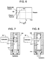
Figure 6 is a graphical representation of steady-state pressure achieved above a pressure threshold to activate the valve illustrated inFigure 5 , according to an embodiment of the present invention; -
Figure 7 is a schematic cross-sectional view of an embodiment of an actuator for use with the valve illustrated inFigure 5 , according to an embodiment of the present invention; -
Figure 8 is a schematic cross-sectional view of the actuator illustrated inFigure 7 in a different operational configuration, according to an embodiment of the present invention; -
Figure 9 is a cross-sectional view of an embodiment of a service tool, according to an embodiment of the present invention; -
Figure 10 is a schematic illustration demonstrating fluid flow through the service tool when the service tool is in the operational mode illustrated inFigure 9 , according to an embodiment of the present invention; -
Figure 11 is a cross-sectional view of the service tool illustrated inFigure 9 but in a different operational mode, according to an embodiment of the present invention; -
Figure 12 is a schematic illustration demonstrating fluid flow through the service tool when the service tool is in the operational mode illustrated inFigure 11 , according to an embodiment of the present invention; -
Figure 13 is a cross-sectional view of the service tool illustrated inFigure 9 but in a different operational mode, according to an embodiment of the present invention; -
Figure 14 is a schematic illustration demonstrating fluid flow through the service tool when the service tool is in the operational mode illustrated inFigure 13 , according to an embodiment of the present invention; -
Figure 15 is a cross-sectional view of the service tool illustrated inFigure 9 but in a different operational mode, according to an embodiment of the present invention; -
Figure 16 is a schematic illustration demonstrating fluid flow through the service tool when the service tool is in the operational mode illustrated inFigure 15 , according to an embodiment of the present invention; -
Figure 17 is a cross-sectional view taken generally across the axis of the service tool to illustrate fluid flow passages along the service tool, according to an embodiment of the present invention; -
Figure 18 is a cross-sectional view taken generally across the axis of the service tool to illustrate fluid flow passages along the service tool, according to another embodiment of the present invention; and -
Figure 19 is a schematic illustration of an embodiment of a trigger device that can be used to actuate components in the service string, according to an embodiment of the present invention. - In the following description, numerous details are set forth to provide an understanding of the present invention. However, it will be understood by those of ordinary skill in the art that the present invention may be practiced without these details and that numerous variations or modifications from the described embodiments may be possible.
- The present invention relates to a system and methodology for facilitating the operation of a service string in a downhole environment. The service string comprises a service tool that may be moved downhole into a wellbore to a desired formation location. The service tool is used in conjunction with other downhole well equipment, such as a sandface assembly. The service tool may be moved through several operational modes without physically sliding the service tool relative to the sandface assembly, i.e. without lineal movement of the service tool within the sandface assembly otherwise caused by movement of the service string.
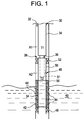
- Referring generally to
Figure 1 , an embodiment of awell system 30 is illustrated as installed in awellbore 32. In this embodiment,well system 30 comprises aservice string 34 having aservice tool 36. Theservice tool 36 can be moved downhole intowellbore 32 for interaction withdownhole equipment 38, such as a sandface assembly. In many applications, the service string and the sandface assembly are coupled together at the surface and conveyed downhole as a single unit. After reaching the desired depth and undergoing preliminary operations, the service string is decoupled from the sandface assembly. - The
wellbore 32 can be vertical or deviated depending on the type of well application and/or well environment in whichservice string 34 is used. Generally,wellbore 32 is drilled into ageological formation 40 containing desirable production fluids, such as petroleum. In at least some applications,wellbore 32 is lined with awellbore casing 42. A plurality ofperforations 44 is formed throughwellbore casing 42 to enable flow of fluids between the surroundingformation 40 and thewellbore 32. Alternatively, the wellbore may be unlined. In this latter case, the top end of the sandface assembly is positioned in the lower end of the casing before the open hole section begins. - In the embodiment illustrated,
sandface assembly 38 comprises abottom hole assembly 46. In some applications, thebottom hole assembly 46 extends into cooperation with alower packer 48, installed on a previous trip downhole. In other applications, e.g. open hole applications, thelower packer 48 is not necessary. Thebottom hole assembly 46 has areceptacle structure 50 into whichservice tool 36 ofservice string 34 is inserted for the performance of various procedures. In one example ofbottom hole assembly 46, thereceptacle structure 50 comprises a circulation housing having one ormore ports 51 through which gravel is placed via the service tool. In this embodiment, the circulation housing also may include a closing sleeve (not shown) which is closed after the process of gravel deposition is completed. Thebottom hole assembly 46 also comprises a gravel packing (GP)packer 52 positioned betweenreceptacle structure 50 and the wall ofwellbore 32. The circulation housing andgravel packing packer 52 effectively provide the receptacle that works in cooperation withservice string 34. By way of example, cooperative features may include a mechanical attachment at the top ofpacker 52 for receiving the service tool, and polish bores can be located above and belowcirculation port 51 to ensure gravel deposition is directed only throughport 51. Thebottom hole assembly 46 further comprises ascreen assembly 54 that may be formed of one or more individual screens. In some applications,service string 34,service tool 36 andbottom hole assembly 46 are used in cooperation to carry out a gravel packing operation in which agravel pack 56 is placed in the region ofwellbore 32 generally surroundingscreen 54. -
Service tool 36 andsandface assembly 38 can be used to carry out a variety of procedures during a given operation, such as a gravel packing operation. Additionally, wellsystem 30 may be switched between many procedures without movement ofservice string 34. In other words, theservice string 34 andservice tool 36 "sit still" relative tobottom hole assembly 46 instead of continuously being "pulled up" or "slacked off' to cause changes from one procedure to another. - As illustrated schematically in
Figure 2 , theservice tool 36 andbottom hole assembly 46 rely on avalve system 58 to achieve desired operating modes without movement, i.e. lifting or settling, of theservice tool 36 insideGP packer 52. By way of example,valve system 58 can be used in any of the operating modes A-G during a gravel packing operation. The valve system operating modes control the flow of fluids between various wellbore regions, such as the tubing above GP packer 52 (T1), the tubing below GP packer 52 (T2), the annulus above GP packer 52 (A1), and the annulus below GP packer 52 (A2). (See alsoFigure 1 ). - For example, during running-in-hole of
service string 34 to perform a gravel packing operation,valve system 58 is placed in configuration A which enables the open flow of fluid from T1 to T2 and from A2 to A1 during movement downhole. Once at the desired wellbore position, the setting ofpacker 52 is achieved by actuatingvalve system 58 to configuration B in which fluid flow is blocked between T1 and T2. After settingpacker 52, an annulus test can be performed by actuatingvalve system 58 to configuration C in which flow between A1 and A2 is blocked. An operational mode for spotting fluids prior to the gravel pack is achieved by actuatingvalve system 58 to configuration D in which fluids may be flowed down the service string at T1 and returned via the annulus at A1. - In this example, the actual gravel packing is initiated by actuating
valve system 58 to configuration E which allows the gravel slurry to flow from T1 to A2 to formgravel pack 56 along the exterior ofscreen 54. The carrier fluid then flows to T2 and is directed out of theservice tool 36 to the annulus at A1 for return to the surface. Subsequently,valve system 58 may be placed in a reversing configuration which is illustrated as configuration F. In this configuration, fluid may be flowed down through A1 and returned via the service string tubing at T1.Valve system 58 also may be adjusted to a breaker configuration G that facilitates the breaking or removal of filter cake whenservice tool 36 is removed fromwellbore 32. By removing the need to physically move theservice string 34 to adjust the valve configurations, premature breakage of the filter cake is avoided. - The
valve system 58 may be actuated between many operational configurations with no movement ofservice string 34 relative topacker 52. Other changes between operational configurations only require a simple "pull up" input or a "slack off" input to cause a slight movement aboveGP packer 52 rather than movingservice tool 36 withinreceptacle structure 50. The ability to easily change from one valve system configuration to another with no or minimal movement of the service string provides a much greater degree of functionality with respect to the operation of the well system. For example, the sequential valve configuration changes from configuration B to configuration D can be repeated or reversed. Additionally, the circulating configuration E and the reversing configuration F are readily reversible and can be repeated. Accordingly,valve system 58 provides great functionality to achieve a desired well operation, e.g. gravel packing operation, without being susceptible to sticking problems and without requiring the operational finesse of conventional systems. - Referring generally to
Figure 3 , a schematic illustration of one embodiment ofvalve system 58 is illustrated. In this embodiment,valve system 58 comprises, for example, asleeve valve 60, alower tubing valve 62, anupper tubing valve 64, and asleeve valve 66.Lower tubing valve 62 andupper tubing valve 64 may be designed as ball valves, however other types of valves also may be used. Additionally,valves valve control system 68 able to individually actuate thevalves service string 34 relative topacker 52. - Control signals can be sent to
valve control system 68 via, for example, pressure signals, pressure signals on the annulus, load, e.g. tensile, signals, flow rate signals, other wireless communication signals sent downhole, and electromagnetic signals. In one embodiment,valve control system 68 receives pressure signals sent via the annulus surroundingservice string 34 and appropriately actuates one or more of theindividual valves annular valve 60 is used to control flow between the annulus and the service string and is actuated between open and closed positions with string weight. For example, theservice string 34 may be pulled up, i.e. placed in tension for specific command sequences, and the string weight may be slacked-off, i.e. placed under a set down load, for circulation operations. Alternatively, the valve may be designed to open and allow circulation operations when the service string is placed under tension and to close for command sequences when weight is slacked off.Valves Figure 2 .Valve control system 68 also may comprise anuplink telemetry system 70 able to output signals, e.g. electrical signals, optical signals, wireless signals, etc., to the surface to confirm the positions of individual valves. - Although other types of
valve control systems 68 can be implemented, one example uses an intelligent remote implementation system (IRIS) control technology available from Schlumberger Corporation. An IRIS basedcontrol system 68 is able to recognize signatures in the form of, for example, pressure signatures, flow rate signatures or tensile signatures. As illustrated inFigure 4 , one embodiment of an IRIS basedcontrol system 68 comprises acontrol module 72 having apressure sensor 74 positioned to sense low-pressure, pressure pulse signatures, e.g.pressure pulse signature 76 illustrated inFigure 4 . Thepressure sensor 74 is coupled to controlelectronics 78 having a microprocessor which decodes the pressure pulse signature. The microprocessor compares a given pressure pulse signature against commands in a tool library. If a match is found, thecontrol electronics 78 outputs an appropriate signal to anactuator 80 which opens and/or closes the appropriate valve. In this embodiment,actuator 80 comprises hydrostatic and atmospheric chambers that enable hydraulic control over each valve,e.g. valve electronics 78 andactuator 80 via abattery 82. - With control systems, such as the IRIS based control system available from Schlumberger Corporation, an over-ride can be used to disable
electronics 78 and to move the valves to a standard gravel packing operational position. In this embodiment, a high pressure, e.g. approximately 4000 psi, is applied through the annulus to over-ridecontrol 72. For example,control 72 may be provided with a rupture disc (not shown) that ruptures upon sufficient annulus pressure to enable manipulation ofservice tool 36 to a default position via the pressurized annulus fluid. By way of example, the over-ride may be designed to releaseservice tool 36 frompacker 52 while openinglower valve 62, openingport body valve 66, and closingupper valve 64. Theservice tool 36 can then be operated in this standard service tool configuration. - Other methods and mechanisms also can be used to control one or more of the valves of
valve system 58. For example,lower valve 62 can be designed to be responsive to a ball passing through an obstruction in a proximate bore. The obstruction can be a collet device that flexes as the ball passes through. The control senses the flexing and causes lower valve actuation. The ball that passes through the flexing collet can be dissolvable such that it presents no obstruction after performing its primary function. In this embodiment, flow is again enabled when the ball is dissolved.Lower valve 62 also can be designed as a ball valve responsive to a predetermined fluid flow. For example, fluid flow through a venturi can be used to create a pressure drop that is used directly or in conjunction with an appropriate electronic actuator to actuatevalve 62 to a desired position, e.g. a closed position. The flow activated control approach also can be used as a backup for a control system, such as the control system described with reference toFigure 4 . In another embodiment,valve 62 is a ball valve controlled by acontrol device 84, such as the device schematically illustrated inFigure 5 .Control device 84 can be designed to respond to, for example, steady state sensing, flow signatures, and/or a dissolvable ball flexing an obstruction in a proximate bore, as well as other inputs. As illustrated inFigure 6 , one example ofcontrol device 84 is designed to respond to a steady-state condition sensed in the wellbore. Another method to controllower valve 62 is to make the valve responsive to a predetermined flow signature. - In this latter embodiment, the first actuation of
lower ball valve 62 or other downhole device is performed in response to the sensing of a steady-state condition. The steady-state condition is detected by, for example, unchanging magnitudes of pressure and/or temperature. For example,control device 84 can be designed to actuate when pressure P satisfies the steady state condition at time tn. Satisfaction of the steady-state condition requires that: P(tn) - P(tn-1) ∼ 0; P(tn-1) - P(tn-2) ∼ 0; etc. for t = the predetermined number of times samples. The same approach can be used for determining a steady-state temperature condition necessary for actuation ofvalve 62. - As illustrated graphically in
Figure 6 , thelower ball valve 62 or other appropriate component is actuated when a measured parameter or parameters, e.g. pressure and/or temperature, reaches a steady-state level 102 over a predetermined period oftime 104 and above apredetermined threshold 106. The processing for determining an appropriate steady-state condition occurs if the subject parameter or parameters exceed the programmed threshold values. Then, each parameter is sampled at a given frequency to achieve n number of samples in a predetermined period of time. If the measured parameter level for each successive time interval is acceptably small according to the system logic, then the steady-state condition is satisfied andactuator 96 is actuated to change the operational position ofvalve 62 or other controlled device. However, other methods and mechanisms can be employed to accomplish initial actuation ofvalve 62, such as the dissolvable ball and other methods discussed above. - Referring again to
Figure 5 , another embodiment ofcontrol device 84 is designed to receive a pressure signature on the annulus, decode it, and compare it to a command library. If a match is found,control device 84 actuates a solenoid that allows hydrostatic pressure to actuate the correct valve. In the example illustrated,control device 84 comprises atransducer 86 which receives the pressure and/or temperature signal. Thetransducer 86 outputs the signal to acontroller board 88 which processes the signals. By way of example,controller board 88 comprises adigitizer 90 which digitizes the signal for amicroprocessor 92 that utilizes decodinglogic 94 for determining when an appropriate signal has been sensed. Upon sensing the predetermined signal,controller board 88 outputs an appropriate control signal to anactuator 96 which may be powered via hydrostatic pressure supplied by ahydrostatic pressure source 98. Theactuator 96 actuateslower valve 62, for example, to a closed position. Thecontroller board 88 is powered by abattery 100. It should be noted thatcontrol device 84 can be used to actuate a variety of other devices withinwell system 30 or within other types of downhole equipment. - By way of example,
actuator 96 may comprise an electro-mechanical device 108 coupled tohydrostatic pressure source 98, as illustrated inFigure 7 . Electro-mechanical device 108 comprises apiston 110 that is selectively displaced to allow flow fromhydrostatic pressure source 98 into achamber 112 that is initially at atmospheric pressure.Piston 110 can be moved by a variety of mechanisms, such as by a solenoid or a motor powered viabattery 100. As illustrated inFigure 8 , the hydrostatic pressure applied withinchamber 112 enables useful work, such as the translation of apower piston 114. The translation ofpiston 114 is used to, for example, rotate a ball within alower ball valve 62 or to achieve another desired actuation within a downhole component. - Referring generally to
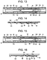
Figure 9 , one specific embodiment ofservice tool 36 inserted intobottom hole assembly 46 is illustrated in greater detail. In this embodiment,annular valve 60 is a sliding valve that may be moved between an open, flow position and a closed position.Annular valve 60 comprises at least oneport 116 that enables flow between an internal annulus ofservice tool 36 and awellbore region 120, e.g. annulus, surrounding the service tool, whenvalve 60 is in an open position. Accordingly,annular valve 60 enables flow between T1 and A1 (whenvalves valve 64 is open) aboveGP packer 52. For reference,Figure 9 illustratesannular valve 60 in a closed position. - In the embodiment illustrated in
Figure 9 ,valves control module 72 which may be an IRIS based control module responsive to pressure signatures sent downhole, as described previously in this document. Each of thevalves service string 34. The pressure signals are directed to controlmodule 72 via aport 122 connected to a conduit or snorkel 124 that extends tosensor 74 of control module 72 (see alsoFigure 4 ). In this embodiment,lower valve 62 andupper valve 64 both comprise ball valves that are movable between an open, flow position alongtubing interior 118 and a closed position. However, one or both of these valves can be designed to move to selected partially closed positions, thus enabling use of such valve or valves to control the rate of fluid flow alongtubing interior 118.Port body valve 66 may comprise a sliding valve selectively moved bycontrol module 72 between an open, flow position and a closed position. In the open position,valve 66 cooperates with aflow port 126 to enable flow between thetubing interior 118 ofservice tool 36 and awellbore region 128, e.g. annulus, surrounding the bottom hole assembly and service tool. For reference,Figure 9 illustratesport body valve 66 in a closed position, andball valves - The
service tool 36 andbottom hole assembly 46 illustrated inFigure 9 can be used to carry out several different gravel packing procedures without movingservice tool 36 withinbottom hole assembly 46. In one embodiment of a gravel packing operation, theservice string 34 is run-in-hole to the desired wellbore location. As theservice string 34 is run-in-hole, the various valves are positioned as illustrated inFigure 9 . In other words,annulus valve 60 is closed,port body valve 66 is closed,upper valve 64 is open andlower valve 62 is open. As further illustrated schematically inFigure 10 , this allows the free flow of fluid alongtubing interior 118, as indicated byarrows 129. In other words, the wash-down path remains open during running intowellbore 32. - When the
service tool 36 and thebottom hole assembly 46 are properly positioned withinwellbore 32,lower ball valve 62 is actuated to a closed position, as illustrated inFigure 11 . The initial actuation can be achieved by a variety of methods, including use of a dedicated control device,e.g. control device 84, or use of other actuation techniques. (In one example, thelower valve 62 can be moved to the closed position to enable application of pressure in thetubing interior 118 for pressure operations upon reaching a steady-state condition with respect to pressure and/or temperature within the wellbore.) In the closed position illustrated inFigure 11 , pressure can be applied alongtubing interior 118 and through anannular channel 130 to setGP packer 52. The pressure is directed as indicated byarrows 132 inFigure 12 and then intoannular channel 130. Alternatively, a pressure signature can be sent along the path indicated byarrows 132 to anappropriate trigger device 134 used to setpacker 52. In one embodiment,trigger device 134 is an IRIS based trigger system designed similar to that described with respect to controlmodule 72 so that a unique pressure signature can be detected and processed by the trigger device. The trigger device then controls a hydraulic actuator which expands and setspacker 52. - Subsequently, the wellbore annulus is pressurized to test the seal formed by
GP packer 52. Theservice string 34 is then manipulated between pulling and slacking off weight to effectively push and pull onpacker 52 which tests the ability of the packer to take weight. If thepacker 52 is properly set, a slackjoint portion 136 ofservice tool 36 is released to enable the opening and closing ofannular valve 60 by movement of slackjoint portion 136 relative to the stationary portion ofservice tool 36 withinbottom hole assembly 46. The slackjoint portion 136 can be released via a variety of release mechanisms. For example, a trigger device, such astrigger device 134, can be used to move arelease catch 138, thereby releasing slackjoint portion 136 for movement ofvalve 60 between open and closed positions. Other release mechanisms e.g. shear pins responsive to annulus pressure to disengage a mechanical lock and other shear mechanisms, also can be used to temporarily lock slackjoint portion 136 to the remainder ofservice tool 36 during the initial stages of the gravel packing operation. - Once slack
joint portion 136 is released, weight is slacked-offservice string 34 to moveannular valve 60 into an open position, as illustrated inFigure 13 . This position allows an operator to spot fluids through the openannular valve 60 into the surrounding annulus. This position is also known as a reverse or reverse flow position that enables a reverse flow of fluids, as indicated byarrows 140 inFigure 14 . - The
service string 34 is then pulled up to closeannular valve 60. Whileannular valve 60 is in the closed position, pressure signatures are sent downhole and communicated to controlmodule 72. In response to the pressure signatures,control module 72 actuates the triple valve and moveslower valve 62 to an open position,upper valve 64 to a closed position, andport body valve 66 to an open position. The tension onservice string 34 is then slacked off to again openannular valve 60, as illustrated inFigure 15 . In this configuration, gravel pack slurry is pumped downtubing interior 118 and out into the annulus throughports 126. The gravel is then deposited aroundscreen 54, and the carrier fluid is routed upwardly through a washpipe from a lower end ofbottom hole assembly 46. The carrier fluid flows upwardly throughlower valve 62 aroundupper valve 64 viaport 130 and out into the annulus throughport 116 ofannular valve 60. The flow path of the gravel packing operation is illustrated schematically viaarrows 142 inFigure 16 . In this embodiment, the gravel slurry moves down intolower annulus 128, with clear returns moving up along an interior side of the control module. - Following development of
gravel pack 56 around screen 54 (seeFigure 1 ),service string 34 is picked up slightly to move floatingtop portion 136 and again closeannular valve 60. An appropriate pressure signature is then sent downhole to controlmodule 72. Based on this pressure signature,control module 72 closeslower valve 62, opensupper valve 64, and closesport body valve 66. The pull onservice string 34 is then slacked off to again openannular valve 60, which places theservice tool 36 in the reverse circulation configuration illustrated inFigure 13 . In this reverse circulation configuration, fluid can be flowed down the annulus and the unused gravel packing slurry can be pushed up to the surface throughtubing interior 118. - Upon completion of the reverse circulation,
service string 34 is again lifted slightly to move floatingtop portion 136 and closeannular valve 60. Then, an appropriate pressure signature is sent downhole to controlmodule 72 which openslower valve 62. At this time,service tool 36 also is undocked fromGP packer 52 andbottom hole assembly 46 to place the service tool in the "breaker" position. In this position the service tool is configured as a pipe with a through-bore, whereby fluid can be circulated straight down to remove the filter cake accumulated along the wellbore. Theservice tool 36 may be released frompacker 52 via a variety of release mechanisms. In one embodiment, a trigger device, such astrigger device 134, can be used to actuate a release that disengagesservice tool 36 frompacker 52 andbottom hole assembly 46. Other release mechanisms, such as collets, hydraulically actuated latch mechanisms, mechanically actuated latch mechanisms, or other latch mechanisms, also can be used to enable engagement and disengagement of the service tool from the bottom hole assembly. - Flow of fluid between certain ports, such as
ports 130 andports 116 can be achieved by creating flow paths along abody 144 ofservice tool 36. By way of example, flowpaths 146 can be formed by creating a plurality of drilledbypass holes 148 extending generally longitudinally throughbody 144, as illustrated in the cross-sectional view ofFigure 17 . Alternative types of flow paths also can be created. For example,body 144 may be formed by placing acentral valve body 150 within a surrounding shroud orhousing 152, as illustrated inFigure 18 . Theflow paths 146 are thus created intermediate thecentral valve body 150 and the surroundingshroud 152. - As discussed above, one or
more trigger devices 134 can incorporate an IRIS based control system, such as those available from Schlumberger Corporation. The one ormore trigger devices 134 can be used, for example, to accomplish one-time actuation, such as the release of floatingtop portion 136, the release ofservice tool 36 frompacker 52, and/or the setting ofGP packer 52. Separate devices may be used for each specific action, or asingle trigger device 134 can be designed with a plurality ofactuators 154, as illustrated inFigure 19 . As described with respect to controlmodule 72, eachtrigger device 134 controls the actuation of one ormore actuators 154 upon appropriate output fromtrigger device electronics 156.Device electronics 156 comprises aprocessor 158 programmed to recognize a specific signature or signatures, such as a pressure signature received by apressure sensor 160. Thetrigger device 134 also may comprise aninternal battery 162 topower device electronics 156 andactuators 154. As described above with respect to controlmodule 72 and steady-state actuation device 84,actuators 154 can be designed to utilize hydraulic pressure from the environment or from a specific hydraulic pressure source to perform the desired work. - In some applications, it may be desirable to confirm operating configurations of the
service tool 36. The tracking of pressure changes in the tubing and/or the annulus can confirm specific changes in operating configuration. For example, changing the valve configuration from a reverse configuration, as illustrated inFigure 13 , to a circulate configuration, as illustrated inFigure 15 , can be confirmed by tracking pressure changes intubing interior 118. Similarly, changing the valve configuration from a circulate configuration to a reverse configuration also can be confirmed. - In the first example, the change from a reverse configuration to a circulate configuration is confirmed by maintaining pressure in
tubing interior 118. As thelower valve 62 is opened, a pressure loss is observed. At this stage, a small flow rate is maintained alongtubing interior 118. When theupper valve 64 closes, pressure integrity intubing interior 118 is observed, and pressure is maintained intubing interior 118. When theport body valve 66 is opened, a pressure loss is again observed. The specific sequence of pressure losses and pressure integrity enables confirmation that the valve position has changed from a reverse configuration to a circulate configuration.Port 116 is closed to facilitate this observation. - In another example, the change from a circulate configuration to a reverse configuration is confirmed by providing a small flow through the annulus. When the
lower valve 62 is closed, a pressure integrity in the annulus is observed. At this stage, pressure is maintained on the annulus. When theupper valve 64 is opened, a return flow is observed alongtubing interior 118, and a small flow is maintained along the annulus. When the port body valve is closed, no additional losses occur through thecrossover port 126. By tracking this specific sequence of events, proper change from a circulate configuration to a reverse configuration can be confirmed. Furthermore, the flow sweeps gravel from theport body valve 66, thereby increasing its operational reliability. - The specific components used in
well system 30 can vary depending on the actual well application in which the system is used. Similarly, the specific component or components used in forming theservice string 34 and thesandface assembly 38 can vary from one well service application to another. For example, different types and configurations of the valve actuators may be selected while maintaining the ability to shift from one valve configuration to another without moving theservice tool 36 within the receptacle of thesandface assembly 38. - Accordingly, although only a few embodiments of the present invention have been described in detail above, those of ordinary skill in the art will readily appreciate that many modifications are possible without materially departing from the teachings of this invention. Such modifications are intended to be included within the scope of this invention as defined in the claims.
Claims (10)
- A method of performing an operation in a wellbore, comprising the steps of:positioning a service tool (36), coupled with a sandface assembly (38) at a desired location in a wellbore; and characterized in thatthe service tool (36) is a retrievable service tool (36); and buytransitioning the retrievable service tool (36) between circulating flow and reverse flow configurations using a plurality of valves (58) in the service tool (36) by adjusting the plurality of valves (58) in the service tool (36) between a first operational mode and a second operational mode, the transitioning being accomplished without moving the service tool (36) with respect to the wellbore.
- The method as recited in claim 1, further comprising actuating at least one valve of the plurality of valves (58) upon sensing a steady-state condition in the wellbore.
- The method as recited in claim 1, wherein adjusting comprises adjusting at least three valVes via a control nodule responsive to (a) unique control signatures sent downhole, (b) wireless signals sent downhole; (c) a pressure signature sent downhole, (d) pressure signals on the annulus, (e) load signatures on a work string coupled to the service tool (36), or (f) electromagnetic signatures sent downhole.
- The method as recited in claim 1, further comprising confirming a change in the flow configuration upon adjustment of the plurality of valves (58).
- The methods as recited in claim 1, wherein transitioning comprises shifting the service tool (36) from the circulating flow configuration to the reverse flow configuration.
- The method as recited in claim 1, wherein transitioning comprises shifting the service tool (36) from the reverse flow configuration to the circulating flow configuration.
- The method as recited in claim 1, wherein positioning comprises releasably coupling the service tool (36) with a bottom hole assembly having a GP packer, the method further comprising:using the fluid flow to form a gravel pack adjacent to the desired location within the wellbore; andupon completion of the gravel pack, disengaging the service tool (36) from the bottom hole assembly.
- A system for use in performing an operation in a well, ccomprising:a service tool (36): and characterized in thatthe service tool (36) is releasably couplable with a sandface assembly (38) located downhole in a wellbore, the service tool (36) comprising:a plurality of valves (58) individually actuable to transition the tool (36) between circulating flow and reverse flow configurations by adjusting the plurality of valves (58) between a first operational mode and a second operational mode, the transitioning being accomplished without moving the servile tool (36) with respect to the wellbore, the service tool (36) being releasable from the sandface assembly (38) to enable retrieval of the service tool (36).
- The system as recited in claim 8, wherein the plurality of valves (58) comprises at least three valves individually actuable by a control module within the service tool (36).
- The system as recited in claim 9, wherein the control module comprises a sensor to sense a parameter signature sent downhole, the control module being able to adjust the plurality of valves (58) for transitioning the service tool (36) between the circulating and reverse flow configurations.
Applications Claiming Priority (3)
| Application Number | Priority Date | Filing Date | Title |
|---|---|---|---|
| US56645906A | 2006-12-04 | 2006-12-04 | |
| US11/626,739 US8056628B2 (en) | 2006-12-04 | 2007-01-24 | System and method for facilitating downhole operations |
| PCT/US2007/080907 WO2008070271A2 (en) | 2006-12-04 | 2007-10-10 | System and method for facilitating downhole operations |
Publications (3)
| Publication Number | Publication Date |
|---|---|
| EP2115268A2 EP2115268A2 (en) | 2009-11-11 |
| EP2115268A4 EP2115268A4 (en) | 2011-06-15 |
| EP2115268B1 true EP2115268B1 (en) | 2016-08-10 |
Family
ID=39493619
Family Applications (1)
| Application Number | Title | Priority Date | Filing Date |
|---|---|---|---|
| EP07853896.4A Not-in-force EP2115268B1 (en) | 2006-12-04 | 2007-10-10 | System and method for facilitating downhole operations |
Country Status (9)
| Country | Link |
|---|---|
| US (2) | US8056628B2 (en) |
| EP (1) | EP2115268B1 (en) |
| CN (1) | CN101595274B (en) |
| AU (1) | AU2007329773B2 (en) |
| BR (1) | BRPI0719349A2 (en) |
| CA (1) | CA2673102C (en) |
| EG (1) | EG26724A (en) |
| MY (2) | MY149125A (en) |
| WO (1) | WO2008070271A2 (en) |
Families Citing this family (136)
| Publication number | Priority date | Publication date | Assignee | Title |
|---|---|---|---|---|
| US9109429B2 (en) | 2002-12-08 | 2015-08-18 | Baker Hughes Incorporated | Engineered powder compact composite material |
| US8403037B2 (en) | 2009-12-08 | 2013-03-26 | Baker Hughes Incorporated | Dissolvable tool and method |
| US8327931B2 (en) | 2009-12-08 | 2012-12-11 | Baker Hughes Incorporated | Multi-component disappearing tripping ball and method for making the same |
| US9079246B2 (en) | 2009-12-08 | 2015-07-14 | Baker Hughes Incorporated | Method of making a nanomatrix powder metal compact |
| US9101978B2 (en) | 2002-12-08 | 2015-08-11 | Baker Hughes Incorporated | Nanomatrix powder metal compact |
| US9682425B2 (en) | 2009-12-08 | 2017-06-20 | Baker Hughes Incorporated | Coated metallic powder and method of making the same |
| US8056628B2 (en) | 2006-12-04 | 2011-11-15 | Schlumberger Technology Corporation | System and method for facilitating downhole operations |
| US8245782B2 (en) * | 2007-01-07 | 2012-08-21 | Schlumberger Technology Corporation | Tool and method of performing rigless sand control in multiple zones |
| US20090033516A1 (en) * | 2007-08-02 | 2009-02-05 | Schlumberger Technology Corporation | Instrumented wellbore tools and methods |
| US20090145603A1 (en) * | 2007-12-05 | 2009-06-11 | Baker Hughes Incorporated | Remote-controlled gravel pack crossover tool utilizing wired drillpipe communication and telemetry |
| US9309735B2 (en) | 2008-06-17 | 2016-04-12 | Schlumberger Technology Corporation | System and method for maintaining operability of a downhole actuator |
| US7775273B2 (en) * | 2008-07-25 | 2010-08-17 | Schlumberber Technology Corporation | Tool using outputs of sensors responsive to signaling |
| US8496055B2 (en) * | 2008-12-30 | 2013-07-30 | Schlumberger Technology Corporation | Efficient single trip gravel pack service tool |
| US8371386B2 (en) * | 2009-07-21 | 2013-02-12 | Schlumberger Technology Corporation | Rotatable valve for downhole completions and method of using same |
| US9567843B2 (en) | 2009-07-30 | 2017-02-14 | Halliburton Energy Services, Inc. | Well drilling methods with event detection |
| US9528334B2 (en) | 2009-07-30 | 2016-12-27 | Halliburton Energy Services, Inc. | Well drilling methods with automated response to event detection |
| US8230924B2 (en) * | 2009-09-03 | 2012-07-31 | Baker Hughes Incorporated | Fracturing and gravel packing tool with upper annulus isolation in a reverse position without closing a wash pipe valve |
| US8528641B2 (en) * | 2009-09-03 | 2013-09-10 | Baker Hughes Incorporated | Fracturing and gravel packing tool with anti-swabbing feature |
| US8261817B2 (en) * | 2009-11-13 | 2012-09-11 | Baker Hughes Incorporated | Modular hydraulic operator for a subterranean tool |
| US8528633B2 (en) | 2009-12-08 | 2013-09-10 | Baker Hughes Incorporated | Dissolvable tool and method |
| US9227243B2 (en) | 2009-12-08 | 2016-01-05 | Baker Hughes Incorporated | Method of making a powder metal compact |
| US10240419B2 (en) | 2009-12-08 | 2019-03-26 | Baker Hughes, A Ge Company, Llc | Downhole flow inhibition tool and method of unplugging a seat |
| US9243475B2 (en) | 2009-12-08 | 2016-01-26 | Baker Hughes Incorporated | Extruded powder metal compact |
| US9127515B2 (en) | 2010-10-27 | 2015-09-08 | Baker Hughes Incorporated | Nanomatrix carbon composite |
| US8573295B2 (en) | 2010-11-16 | 2013-11-05 | Baker Hughes Incorporated | Plug and method of unplugging a seat |
| US8425651B2 (en) | 2010-07-30 | 2013-04-23 | Baker Hughes Incorporated | Nanomatrix metal composite |
| WO2011085215A2 (en) * | 2010-01-08 | 2011-07-14 | Schlumberger Canada Limited | Wirelessly actuated hydrostatic set module |
| US8424610B2 (en) | 2010-03-05 | 2013-04-23 | Baker Hughes Incorporated | Flow control arrangement and method |
| EP2585683A2 (en) * | 2010-06-24 | 2013-05-01 | Chevron U.S.A., Inc. | Apparatus and method for remote actuation of a downhole assembly |
| GB201012176D0 (en) | 2010-07-20 | 2010-09-01 | Metrol Tech Ltd | Well |
| GB201012175D0 (en) | 2010-07-20 | 2010-09-01 | Metrol Tech Ltd | Procedure and mechanisms |
| US8776884B2 (en) | 2010-08-09 | 2014-07-15 | Baker Hughes Incorporated | Formation treatment system and method |
| US8596359B2 (en) * | 2010-10-19 | 2013-12-03 | Halliburton Energy Services, Inc. | Remotely controllable fluid flow control assembly |
| US9090955B2 (en) | 2010-10-27 | 2015-07-28 | Baker Hughes Incorporated | Nanomatrix powder metal composite |
| US9085960B2 (en) * | 2010-10-28 | 2015-07-21 | Weatherford Technology Holdings, Llc | Gravel pack bypass assembly |
| US8739884B2 (en) | 2010-12-07 | 2014-06-03 | Baker Hughes Incorporated | Stackable multi-barrier system and method |
| US8813855B2 (en) | 2010-12-07 | 2014-08-26 | Baker Hughes Incorporated | Stackable multi-barrier system and method |
| US9027651B2 (en) | 2010-12-07 | 2015-05-12 | Baker Hughes Incorporated | Barrier valve system and method of closing same by withdrawing upper completion |
| US9051811B2 (en) | 2010-12-16 | 2015-06-09 | Baker Hughes Incorporated | Barrier valve system and method of controlling same with tubing pressure |
| US8550172B2 (en) * | 2010-12-16 | 2013-10-08 | Baker Hughes Incorporated | Plural barrier valve system with wet connect |
| US8668019B2 (en) * | 2010-12-29 | 2014-03-11 | Baker Hughes Incorporated | Dissolvable barrier for downhole use and method thereof |
| US9181796B2 (en) | 2011-01-21 | 2015-11-10 | Schlumberger Technology Corporation | Downhole sand control apparatus and method with tool position sensor |
| US8955600B2 (en) | 2011-04-05 | 2015-02-17 | Baker Hughes Incorporated | Multi-barrier system and method |
| US9309745B2 (en) | 2011-04-22 | 2016-04-12 | Schlumberger Technology Corporation | Interventionless operation of downhole tool |
| US9080098B2 (en) | 2011-04-28 | 2015-07-14 | Baker Hughes Incorporated | Functionally gradient composite article |
| US8631876B2 (en) | 2011-04-28 | 2014-01-21 | Baker Hughes Incorporated | Method of making and using a functionally gradient composite tool |
| US8651173B2 (en) * | 2011-06-09 | 2014-02-18 | Baker Hughes Incorporated | Modular control system for downhole tool |
| US9139928B2 (en) | 2011-06-17 | 2015-09-22 | Baker Hughes Incorporated | Corrodible downhole article and method of removing the article from downhole environment |
| EP2729657B1 (en) * | 2011-07-05 | 2019-09-04 | Bruce A. Tunget | Cable compatible rig-less operable annuli engagable system for using and abandoning a subterranean well |
| US9707739B2 (en) | 2011-07-22 | 2017-07-18 | Baker Hughes Incorporated | Intermetallic metallic composite, method of manufacture thereof and articles comprising the same |
| US8783365B2 (en) | 2011-07-28 | 2014-07-22 | Baker Hughes Incorporated | Selective hydraulic fracturing tool and method thereof |
| US9833838B2 (en) | 2011-07-29 | 2017-12-05 | Baker Hughes, A Ge Company, Llc | Method of controlling the corrosion rate of alloy particles, alloy particle with controlled corrosion rate, and articles comprising the particle |
| US9643250B2 (en) | 2011-07-29 | 2017-05-09 | Baker Hughes Incorporated | Method of controlling the corrosion rate of alloy particles, alloy particle with controlled corrosion rate, and articles comprising the particle |
| US9057242B2 (en) | 2011-08-05 | 2015-06-16 | Baker Hughes Incorporated | Method of controlling corrosion rate in downhole article, and downhole article having controlled corrosion rate |
| US9033055B2 (en) | 2011-08-17 | 2015-05-19 | Baker Hughes Incorporated | Selectively degradable passage restriction and method |
| US9010442B2 (en) * | 2011-08-29 | 2015-04-21 | Halliburton Energy Services, Inc. | Method of completing a multi-zone fracture stimulation treatment of a wellbore |
| US9109269B2 (en) | 2011-08-30 | 2015-08-18 | Baker Hughes Incorporated | Magnesium alloy powder metal compact |
| US9090956B2 (en) | 2011-08-30 | 2015-07-28 | Baker Hughes Incorporated | Aluminum alloy powder metal compact |
| US9856547B2 (en) | 2011-08-30 | 2018-01-02 | Bakers Hughes, A Ge Company, Llc | Nanostructured powder metal compact |
| US9643144B2 (en) | 2011-09-02 | 2017-05-09 | Baker Hughes Incorporated | Method to generate and disperse nanostructures in a composite material |
| US9133695B2 (en) | 2011-09-03 | 2015-09-15 | Baker Hughes Incorporated | Degradable shaped charge and perforating gun system |
| US9347119B2 (en) | 2011-09-03 | 2016-05-24 | Baker Hughes Incorporated | Degradable high shock impedance material |
| US9187990B2 (en) | 2011-09-03 | 2015-11-17 | Baker Hughes Incorporated | Method of using a degradable shaped charge and perforating gun system |
| US9284812B2 (en) | 2011-11-21 | 2016-03-15 | Baker Hughes Incorporated | System for increasing swelling efficiency |
| US9010416B2 (en) | 2012-01-25 | 2015-04-21 | Baker Hughes Incorporated | Tubular anchoring system and a seat for use in the same |
| US9068428B2 (en) | 2012-02-13 | 2015-06-30 | Baker Hughes Incorporated | Selectively corrodible downhole article and method of use |
| US9016372B2 (en) | 2012-03-29 | 2015-04-28 | Baker Hughes Incorporated | Method for single trip fluid isolation |
| US9016389B2 (en) | 2012-03-29 | 2015-04-28 | Baker Hughes Incorporated | Retrofit barrier valve system |
| US9828829B2 (en) | 2012-03-29 | 2017-11-28 | Baker Hughes, A Ge Company, Llc | Intermediate completion assembly for isolating lower completion |
| US9605508B2 (en) | 2012-05-08 | 2017-03-28 | Baker Hughes Incorporated | Disintegrable and conformable metallic seal, and method of making the same |
| US10030513B2 (en) | 2012-09-19 | 2018-07-24 | Schlumberger Technology Corporation | Single trip multi-zone drill stem test system |
| US9441454B2 (en) * | 2012-10-26 | 2016-09-13 | Weatherford Technology Holdings, Llc | Gravel pack apparatus having actuated valves |
| US10030473B2 (en) | 2012-11-13 | 2018-07-24 | Exxonmobil Upstream Research Company | Method for remediating a screen-out during well completion |
| WO2014100275A1 (en) | 2012-12-19 | 2014-06-26 | Exxonmobil Upstream Research Company | Wired and wireless downhole telemetry using a logging tool |
| US9631485B2 (en) | 2012-12-19 | 2017-04-25 | Exxonmobil Upstream Research Company | Electro-acoustic transmission of data along a wellbore |
| US9557434B2 (en) | 2012-12-19 | 2017-01-31 | Exxonmobil Upstream Research Company | Apparatus and method for detecting fracture geometry using acoustic telemetry |
| US20150292319A1 (en) | 2012-12-19 | 2015-10-15 | Exxon-Mobil Upstream Research Company | Telemetry for Wireless Electro-Acoustical Transmission of Data Along a Wellbore |
| WO2014100272A1 (en) | 2012-12-19 | 2014-06-26 | Exxonmobil Upstream Research Company | Apparatus and method for monitoring fluid flow in a wellbore using acoustic signals |
| US9816373B2 (en) | 2012-12-19 | 2017-11-14 | Exxonmobil Upstream Research Company | Apparatus and method for relieving annular pressure in a wellbore using a wireless sensor network |
| US9945208B2 (en) | 2012-12-21 | 2018-04-17 | Exxonmobil Upstream Research Company | Flow control assemblies for downhole operations and systems and methods including the same |
| US9963960B2 (en) | 2012-12-21 | 2018-05-08 | Exxonmobil Upstream Research Company | Systems and methods for stimulating a multi-zone subterranean formation |
| CA2894495C (en) | 2012-12-21 | 2017-01-10 | Exxonmobil Upstream Research Company | Flow control assemblies for downhole operations and systems and methods including the same |
| CA2894634C (en) | 2012-12-21 | 2016-11-01 | Randy C. Tolman | Fluid plugs as downhole sealing devices and systems and methods including the same |
| MX2016000062A (en) * | 2013-08-02 | 2016-03-09 | Halliburton Energy Services Inc | Downhole power delivery tool powered by hydrostatic pressure. |
| US9816339B2 (en) | 2013-09-03 | 2017-11-14 | Baker Hughes, A Ge Company, Llc | Plug reception assembly and method of reducing restriction in a borehole |
| WO2015073056A1 (en) * | 2013-11-13 | 2015-05-21 | Halliburton Energy Services, Inc. | Gravel Pack Service Tool Used to Set a Packer |
| WO2015080754A1 (en) | 2013-11-26 | 2015-06-04 | Exxonmobil Upstream Research Company | Remotely actuated screenout relief valves and systems and methods including the same |
| WO2015127174A1 (en) | 2014-02-21 | 2015-08-27 | Terves, Inc. | Fluid activated disintegrating metal system |
| US11167343B2 (en) | 2014-02-21 | 2021-11-09 | Terves, Llc | Galvanically-active in situ formed particles for controlled rate dissolving tools |
| US9790762B2 (en) | 2014-02-28 | 2017-10-17 | Exxonmobil Upstream Research Company | Corrodible wellbore plugs and systems and methods including the same |
| US9856720B2 (en) | 2014-08-21 | 2018-01-02 | Exxonmobil Upstream Research Company | Bidirectional flow control device for facilitating stimulation treatments in a subterranean formation |
| US10508536B2 (en) | 2014-09-12 | 2019-12-17 | Exxonmobil Upstream Research Company | Discrete wellbore devices, hydrocarbon wells including a downhole communication network and the discrete wellbore devices and systems and methods including the same |
| US9951596B2 (en) | 2014-10-16 | 2018-04-24 | Exxonmobil Uptream Research Company | Sliding sleeve for stimulating a horizontal wellbore, and method for completing a wellbore |
| US9863222B2 (en) | 2015-01-19 | 2018-01-09 | Exxonmobil Upstream Research Company | System and method for monitoring fluid flow in a wellbore using acoustic telemetry |
| US9910026B2 (en) | 2015-01-21 | 2018-03-06 | Baker Hughes, A Ge Company, Llc | High temperature tracers for downhole detection of produced water |
| US10408047B2 (en) | 2015-01-26 | 2019-09-10 | Exxonmobil Upstream Research Company | Real-time well surveillance using a wireless network and an in-wellbore tool |
| US10378303B2 (en) | 2015-03-05 | 2019-08-13 | Baker Hughes, A Ge Company, Llc | Downhole tool and method of forming the same |
| US10221637B2 (en) | 2015-08-11 | 2019-03-05 | Baker Hughes, A Ge Company, Llc | Methods of manufacturing dissolvable tools via liquid-solid state molding |
| CN106522871B (en) * | 2015-09-15 | 2019-04-05 | 中国石油化工股份有限公司 | A kind of open hole packer |
| US10196886B2 (en) | 2015-12-02 | 2019-02-05 | Exxonmobil Upstream Research Company | Select-fire, downhole shockwave generation devices, hydrocarbon wells that include the shockwave generation devices, and methods of utilizing the same |
| US10221669B2 (en) | 2015-12-02 | 2019-03-05 | Exxonmobil Upstream Research Company | Wellbore tubulars including a plurality of selective stimulation ports and methods of utilizing the same |
| US10309195B2 (en) | 2015-12-04 | 2019-06-04 | Exxonmobil Upstream Research Company | Selective stimulation ports including sealing device retainers and methods of utilizing the same |
| US10016810B2 (en) | 2015-12-14 | 2018-07-10 | Baker Hughes, A Ge Company, Llc | Methods of manufacturing degradable tools using a galvanic carrier and tools manufactured thereof |
| BR112018070412B1 (en) * | 2016-05-10 | 2022-08-23 | Halliburton Energy Services, Inc | DRILL ROD TEST METHOD AND SYSTEM TO EVALUATE A WELL HOLE |
| WO2017204804A1 (en) * | 2016-05-26 | 2017-11-30 | Halliburton Energy Services, Inc. | Hydraulically controlled electric insert safety valve |
| US10364669B2 (en) | 2016-08-30 | 2019-07-30 | Exxonmobil Upstream Research Company | Methods of acoustically communicating and wells that utilize the methods |
| US10526888B2 (en) | 2016-08-30 | 2020-01-07 | Exxonmobil Upstream Research Company | Downhole multiphase flow sensing methods |
| US10344583B2 (en) | 2016-08-30 | 2019-07-09 | Exxonmobil Upstream Research Company | Acoustic housing for tubulars |
| US10590759B2 (en) | 2016-08-30 | 2020-03-17 | Exxonmobil Upstream Research Company | Zonal isolation devices including sensing and wireless telemetry and methods of utilizing the same |
| US10415376B2 (en) | 2016-08-30 | 2019-09-17 | Exxonmobil Upstream Research Company | Dual transducer communications node for downhole acoustic wireless networks and method employing same |
| US10487647B2 (en) | 2016-08-30 | 2019-11-26 | Exxonmobil Upstream Research Company | Hybrid downhole acoustic wireless network |
| US10465505B2 (en) | 2016-08-30 | 2019-11-05 | Exxonmobil Upstream Research Company | Reservoir formation characterization using a downhole wireless network |
| US10697287B2 (en) | 2016-08-30 | 2020-06-30 | Exxonmobil Upstream Research Company | Plunger lift monitoring via a downhole wireless network field |
| CA3031325A1 (en) * | 2016-09-23 | 2018-03-29 | Halliburton Energy Services, Inc. | Systems and methods for controlling fluid flow in a wellbore using a switchable downhole crossover tool |
| CA3012511A1 (en) | 2017-07-27 | 2019-01-27 | Terves Inc. | Degradable metal matrix composite |
| AU2018347465B2 (en) | 2017-10-13 | 2021-10-07 | Exxonmobil Upstream Research Company | Method and system for performing communications using aliasing |
| CN111201454B (en) | 2017-10-13 | 2022-09-09 | 埃克森美孚上游研究公司 | Method and system for performing operations with communications |
| WO2019074657A1 (en) | 2017-10-13 | 2019-04-18 | Exxonmobil Upstream Research Company | Method and system for performing operations using communications |
| US10697288B2 (en) | 2017-10-13 | 2020-06-30 | Exxonmobil Upstream Research Company | Dual transducer communications node including piezo pre-tensioning for acoustic wireless networks and method employing same |
| US10837276B2 (en) | 2017-10-13 | 2020-11-17 | Exxonmobil Upstream Research Company | Method and system for performing wireless ultrasonic communications along a drilling string |
| US10724363B2 (en) | 2017-10-13 | 2020-07-28 | Exxonmobil Upstream Research Company | Method and system for performing hydrocarbon operations with mixed communication networks |
| US10619474B2 (en) * | 2017-11-14 | 2020-04-14 | Saudi Arabian Oil Company | Remotely operated inflow control valve |
| WO2019099188A1 (en) | 2017-11-17 | 2019-05-23 | Exxonmobil Upstream Research Company | Method and system for performing wireless ultrasonic communications along tubular members |
| US10690794B2 (en) | 2017-11-17 | 2020-06-23 | Exxonmobil Upstream Research Company | Method and system for performing operations using communications for a hydrocarbon system |
| US10844708B2 (en) | 2017-12-20 | 2020-11-24 | Exxonmobil Upstream Research Company | Energy efficient method of retrieving wireless networked sensor data |
| US11156081B2 (en) | 2017-12-29 | 2021-10-26 | Exxonmobil Upstream Research Company | Methods and systems for operating and maintaining a downhole wireless network |
| US11313215B2 (en) | 2017-12-29 | 2022-04-26 | Exxonmobil Upstream Research Company | Methods and systems for monitoring and optimizing reservoir stimulation operations |
| CA3090799C (en) | 2018-02-08 | 2023-10-10 | Exxonmobil Upstream Research Company | Methods of network peer identification and self-organization using unique tonal signatures and wells that use the methods |
| US11268378B2 (en) | 2018-02-09 | 2022-03-08 | Exxonmobil Upstream Research Company | Downhole wireless communication node and sensor/tools interface |
| GB2570916B (en) | 2018-02-09 | 2020-08-26 | Weatherford Uk Ltd | Completion system apparatus |
| SG11202006095SA (en) | 2018-03-23 | 2020-07-29 | Halliburton Energy Services Inc | Remote control flow path system for gravel packing |
| US10364659B1 (en) | 2018-09-27 | 2019-07-30 | Exxonmobil Upstream Research Company | Methods and devices for restimulating a well completion |
| US11293280B2 (en) | 2018-12-19 | 2022-04-05 | Exxonmobil Upstream Research Company | Method and system for monitoring post-stimulation operations through acoustic wireless sensor network |
| US11952886B2 (en) | 2018-12-19 | 2024-04-09 | ExxonMobil Technology and Engineering Company | Method and system for monitoring sand production through acoustic wireless sensor network |
| US11073007B2 (en) * | 2019-10-31 | 2021-07-27 | Halliburton Energy Services, Inc. | Methods to perform wellbore strengthening, methods to pulse hydraulic fracture a downhole formation, and wellbore strengthening systems |
| US20240125212A1 (en) * | 2022-10-13 | 2024-04-18 | Baker Hughes Oilfield Operations Llc | Downhole tool, method and system |
Family Cites Families (82)
| Publication number | Priority date | Publication date | Assignee | Title |
|---|---|---|---|---|
| USRE24617E (en) | 1959-03-10 | Method for forming- conduits | ||
| US2340481A (en) * | 1940-06-25 | 1944-02-01 | Ralph B Lloyd | Apparatus for starting flow in wells |
| US3439740A (en) * | 1966-07-26 | 1969-04-22 | George E Conover | Inflatable testing and treating tool and method of using |
| US4372384A (en) | 1980-09-19 | 1983-02-08 | Geo Vann, Inc. | Well completion method and apparatus |
| US4428431A (en) | 1981-05-14 | 1984-01-31 | Baker International Corporation | Perforable screen device for subterranean wells and method of producing multi-lobe zones |
| US4519451A (en) | 1983-05-09 | 1985-05-28 | Otis Engineering Corporation | Well treating equipment and methods |
| US4566538A (en) | 1984-03-26 | 1986-01-28 | Baker Oil Tools, Inc. | Fail-safe one trip perforating and gravel pack system |
| US4944348A (en) | 1989-11-27 | 1990-07-31 | Halliburton Company | One-trip washdown system and method |
| US5174379A (en) * | 1991-02-11 | 1992-12-29 | Otis Engineering Corporation | Gravel packing and perforating a well in a single trip |
| US5377750A (en) * | 1992-07-29 | 1995-01-03 | Halliburton Company | Sand screen completion |
| US5609204A (en) | 1995-01-05 | 1997-03-11 | Osca, Inc. | Isolation system and gravel pack assembly |
| US5636691A (en) * | 1995-09-18 | 1997-06-10 | Halliburton Energy Services, Inc. | Abrasive slurry delivery apparatus and methods of using same |
| US5875852A (en) * | 1997-02-04 | 1999-03-02 | Halliburton Energy Services, Inc. | Apparatus and associated methods of producing a subterranean well |
| US5921318A (en) | 1997-04-21 | 1999-07-13 | Halliburton Energy Services, Inc. | Method and apparatus for treating multiple production zones |
| US5988285A (en) | 1997-08-25 | 1999-11-23 | Schlumberger Technology Corporation | Zone isolation system |
| US5971070A (en) | 1997-08-27 | 1999-10-26 | Halliburton Energy Services, Inc. | Apparatus for completing a subterranean well and associated methods |
| US6427775B1 (en) * | 1997-10-16 | 2002-08-06 | Halliburton Energy Services, Inc. | Methods and apparatus for completing wells in unconsolidated subterranean zones |
| US6059032A (en) | 1997-12-10 | 2000-05-09 | Mobil Oil Corporation | Method and apparatus for treating long formation intervals |
| US6216785B1 (en) * | 1998-03-26 | 2001-04-17 | Schlumberger Technology Corporation | System for installation of well stimulating apparatus downhole utilizing a service tool string |
| US6148915A (en) * | 1998-04-16 | 2000-11-21 | Halliburton Energy Services, Inc. | Apparatus and methods for completing a subterranean well |
| US6758090B2 (en) | 1998-06-15 | 2004-07-06 | Schlumberger Technology Corporation | Method and apparatus for the detection of bubble point pressure |
| WO2000005484A1 (en) | 1998-07-22 | 2000-02-03 | Baker Hughes Incorporated | Apparatus and method for open hole gravel packing |
| US7124824B2 (en) * | 2000-12-05 | 2006-10-24 | Bj Services Company, U.S.A. | Washpipeless isolation strings and methods for isolation |
| US6722440B2 (en) | 1998-08-21 | 2004-04-20 | Bj Services Company | Multi-zone completion strings and methods for multi-zone completions |
| US7201232B2 (en) * | 1998-08-21 | 2007-04-10 | Bj Services Company | Washpipeless isolation strings and methods for isolation with object holding service tool |
| US6302216B1 (en) | 1998-11-18 | 2001-10-16 | Schlumberger Technology Corp. | Flow control and isolation in a wellbore |
| US6575246B2 (en) * | 1999-04-30 | 2003-06-10 | Schlumberger Technology Corporation | Method and apparatus for gravel packing with a pressure maintenance tool |
| US6220353B1 (en) | 1999-04-30 | 2001-04-24 | Schlumberger Technology Corporation | Full bore set down tool assembly for gravel packing a well |
| US6513599B1 (en) * | 1999-08-09 | 2003-02-04 | Schlumberger Technology Corporation | Thru-tubing sand control method and apparatus |
| US6343651B1 (en) * | 1999-10-18 | 2002-02-05 | Schlumberger Technology Corporation | Apparatus and method for controlling fluid flow with sand control |
| US6446729B1 (en) * | 1999-10-18 | 2002-09-10 | Schlumberger Technology Corporation | Sand control method and apparatus |
| US6568474B2 (en) | 1999-12-20 | 2003-05-27 | Bj Services, Usa | Rigless one-trip perforation and gravel pack system and method |
| AU782553B2 (en) * | 2000-01-05 | 2005-08-11 | Baker Hughes Incorporated | Method of providing hydraulic/fiber conduits adjacent bottom hole assemblies for multi-step completions |
| OA12224A (en) | 2000-03-02 | 2006-05-09 | Shell Int Research | Wireless downhole well interval inflow and injection control. |
| US7100690B2 (en) * | 2000-07-13 | 2006-09-05 | Halliburton Energy Services, Inc. | Gravel packing apparatus having an integrated sensor and method for use of same |
| DZ3387A1 (en) | 2000-07-18 | 2002-01-24 | Exxonmobil Upstream Res Co | PROCESS FOR TREATING MULTIPLE INTERVALS IN A WELLBORE |
| US6371210B1 (en) * | 2000-10-10 | 2002-04-16 | Weatherford/Lamb, Inc. | Flow control apparatus for use in a wellbore |
| US6543545B1 (en) | 2000-10-27 | 2003-04-08 | Halliburton Energy Services, Inc. | Expandable sand control device and specialized completion system and method |
| US6488082B2 (en) * | 2001-01-23 | 2002-12-03 | Halliburton Energy Services, Inc. | Remotely operated multi-zone packing system |
| US6622794B2 (en) * | 2001-01-26 | 2003-09-23 | Baker Hughes Incorporated | Sand screen with active flow control and associated method of use |
| US6464006B2 (en) | 2001-02-26 | 2002-10-15 | Baker Hughes Incorporated | Single trip, multiple zone isolation, well fracturing system |
| US6745834B2 (en) | 2001-04-26 | 2004-06-08 | Schlumberger Technology Corporation | Complete trip system |
| GB2376488B (en) * | 2001-06-12 | 2004-05-12 | Schlumberger Holdings | Flow control regulation method and apparatus |
| US6749023B2 (en) * | 2001-06-13 | 2004-06-15 | Halliburton Energy Services, Inc. | Methods and apparatus for gravel packing, fracturing or frac packing wells |
| US7017664B2 (en) * | 2001-08-24 | 2006-03-28 | Bj Services Company | Single trip horizontal gravel pack and stimulation system and method |
| US7331388B2 (en) * | 2001-08-24 | 2008-02-19 | Bj Services Company | Horizontal single trip system with rotating jetting tool |
| EA005438B1 (en) * | 2001-09-07 | 2005-02-24 | Шелл Интернэшнл Рисерч Маатсхаппий Б.В. | Adjustable well screen assembly |
| US6644404B2 (en) | 2001-10-17 | 2003-11-11 | Halliburton Energy Services, Inc. | Method of progressively gravel packing a zone |
| US6719064B2 (en) * | 2001-11-13 | 2004-04-13 | Schlumberger Technology Corporation | Expandable completion system and method |
| CA2412072C (en) | 2001-11-19 | 2012-06-19 | Packers Plus Energy Services Inc. | Method and apparatus for wellbore fluid treatment |
| US6899176B2 (en) * | 2002-01-25 | 2005-05-31 | Halliburton Energy Services, Inc. | Sand control screen assembly and treatment method using the same |
| US6776238B2 (en) | 2002-04-09 | 2004-08-17 | Halliburton Energy Services, Inc. | Single trip method for selectively fracture packing multiple formations traversed by a wellbore |
| US6702020B2 (en) * | 2002-04-11 | 2004-03-09 | Baker Hughes Incorporated | Crossover Tool |
| NO324739B1 (en) * | 2002-04-16 | 2007-12-03 | Schlumberger Technology Bv | Release module for operating a downhole tool |
| US7021384B2 (en) | 2002-08-21 | 2006-04-04 | Packers Plus Energy Services Inc. | Apparatus and method for wellbore isolation |
| US7108067B2 (en) | 2002-08-21 | 2006-09-19 | Packers Plus Energy Services Inc. | Method and apparatus for wellbore fluid treatment |
| US7055598B2 (en) * | 2002-08-26 | 2006-06-06 | Halliburton Energy Services, Inc. | Fluid flow control device and method for use of same |
| US6729407B2 (en) | 2002-09-10 | 2004-05-04 | Baker Hughes Incorporated | Method for removing gravel pack screens |
| US7665535B2 (en) | 2002-12-19 | 2010-02-23 | Schlumberger Technology Corporation | Rigless one-trip system and method |
| US6886634B2 (en) * | 2003-01-15 | 2005-05-03 | Halliburton Energy Services, Inc. | Sand control screen assembly having an internal isolation member and treatment method using the same |
| US6857476B2 (en) | 2003-01-15 | 2005-02-22 | Halliburton Energy Services, Inc. | Sand control screen assembly having an internal seal element and treatment method using the same |
| US6978840B2 (en) * | 2003-02-05 | 2005-12-27 | Halliburton Energy Services, Inc. | Well screen assembly and system with controllable variable flow area and method of using same for oil well fluid production |
| US7165611B2 (en) | 2003-06-10 | 2007-01-23 | Halliburton Energy Services, Inc. | Single trip perforation/packing method |
| US7252152B2 (en) * | 2003-06-18 | 2007-08-07 | Weatherford/Lamb, Inc. | Methods and apparatus for actuating a downhole tool |
| US6981551B2 (en) * | 2003-07-07 | 2006-01-03 | Bj Services Company | Cross-over tool return port cover |
| US7128151B2 (en) * | 2003-11-17 | 2006-10-31 | Baker Hughes Incorporated | Gravel pack crossover tool with single position multi-function capability |
| WO2006015277A1 (en) * | 2004-07-30 | 2006-02-09 | Baker Hughes Incorporated | Downhole inflow control device with shut-off feature |
| US7191833B2 (en) | 2004-08-24 | 2007-03-20 | Halliburton Energy Services, Inc. | Sand control screen assembly having fluid loss control capability and method for use of same |
| US7367395B2 (en) * | 2004-09-22 | 2008-05-06 | Halliburton Energy Services, Inc. | Sand control completion having smart well capability and method for use of same |
| US8336625B2 (en) * | 2004-11-03 | 2012-12-25 | Halliburton Energy Services, Inc. | Fracturing/gravel packing tool with variable direction and exposure exit ports |
| US7322417B2 (en) | 2004-12-14 | 2008-01-29 | Schlumberger Technology Corporation | Technique and apparatus for completing multiple zones |
| US7387165B2 (en) | 2004-12-14 | 2008-06-17 | Schlumberger Technology Corporation | System for completing multiple well intervals |
| US7428924B2 (en) * | 2004-12-23 | 2008-09-30 | Schlumberger Technology Corporation | System and method for completing a subterranean well |
| US7523787B2 (en) * | 2005-11-18 | 2009-04-28 | Halliburton Energy Services, Inc. | Reverse out valve for well treatment operations |
| US7712524B2 (en) | 2006-03-30 | 2010-05-11 | Schlumberger Technology Corporation | Measuring a characteristic of a well proximate a region to be gravel packed |
| US8056628B2 (en) | 2006-12-04 | 2011-11-15 | Schlumberger Technology Corporation | System and method for facilitating downhole operations |
| US7546878B2 (en) | 2006-12-14 | 2009-06-16 | Schlumberger Technology Corporation | Chemical deployment canisters for downhole use |
| US8245782B2 (en) | 2007-01-07 | 2012-08-21 | Schlumberger Technology Corporation | Tool and method of performing rigless sand control in multiple zones |
| US7918276B2 (en) | 2007-06-20 | 2011-04-05 | Schlumberger Technology Corporation | System and method for creating a gravel pack |
| US7950454B2 (en) | 2007-07-23 | 2011-05-31 | Schlumberger Technology Corporation | Technique and system for completing a well |
| US20090145603A1 (en) | 2007-12-05 | 2009-06-11 | Baker Hughes Incorporated | Remote-controlled gravel pack crossover tool utilizing wired drillpipe communication and telemetry |
| US8496055B2 (en) | 2008-12-30 | 2013-07-30 | Schlumberger Technology Corporation | Efficient single trip gravel pack service tool |
-
2007
- 2007-01-24 US US11/626,739 patent/US8056628B2/en active Active
- 2007-10-10 CN CN200780050728.3A patent/CN101595274B/en not_active Expired - Fee Related
- 2007-10-10 CA CA2673102A patent/CA2673102C/en not_active Expired - Fee Related
- 2007-10-10 BR BRPI0719349-1A2A patent/BRPI0719349A2/en not_active IP Right Cessation
- 2007-10-10 WO PCT/US2007/080907 patent/WO2008070271A2/en active Application Filing
- 2007-10-10 MY MYPI20092272A patent/MY149125A/en unknown
- 2007-10-10 AU AU2007329773A patent/AU2007329773B2/en active Active
- 2007-10-10 EP EP07853896.4A patent/EP2115268B1/en not_active Not-in-force
- 2007-10-10 MY MYPI2012005409A patent/MY158734A/en unknown
-
2009
- 2009-06-02 EG EG2009060832A patent/EG26724A/en active
-
2011
- 2011-09-28 US US13/246,997 patent/US8220542B2/en active Active
Also Published As
| Publication number | Publication date |
|---|---|
| AU2007329773A2 (en) | 2009-07-16 |
| EP2115268A4 (en) | 2011-06-15 |
| US20120012312A1 (en) | 2012-01-19 |
| WO2008070271A3 (en) | 2008-12-04 |
| US8056628B2 (en) | 2011-11-15 |
| US20080128130A1 (en) | 2008-06-05 |
| MY149125A (en) | 2013-07-15 |
| EG26724A (en) | 2014-06-18 |
| AU2007329773A1 (en) | 2008-06-12 |
| MY158734A (en) | 2016-11-15 |
| CA2673102A1 (en) | 2008-06-12 |
| CA2673102C (en) | 2015-12-01 |
| CN101595274B (en) | 2014-02-26 |
| WO2008070271A4 (en) | 2009-01-22 |
| CN101595274A (en) | 2009-12-02 |
| WO2008070271A2 (en) | 2008-06-12 |
| AU2007329773B2 (en) | 2013-05-30 |
| US8220542B2 (en) | 2012-07-17 |
| EP2115268A2 (en) | 2009-11-11 |
| BRPI0719349A2 (en) | 2014-01-07 |
Similar Documents
| Publication | Publication Date | Title |
|---|---|---|
| EP2115268B1 (en) | System and method for facilitating downhole operations | |
| US7428924B2 (en) | System and method for completing a subterranean well | |
| US6302216B1 (en) | Flow control and isolation in a wellbore | |
| US8118098B2 (en) | Flow control system and method for use in a wellbore | |
| EP2673460B1 (en) | Completion assembly | |
| EP2189622B1 (en) | Casing valves system for selective well stimulation and control | |
| US7673689B2 (en) | Dual flapper barrier valve | |
| US6575246B2 (en) | Method and apparatus for gravel packing with a pressure maintenance tool | |
| WO2006015277A1 (en) | Downhole inflow control device with shut-off feature | |
| WO2012145735A1 (en) | Interventionless operation of downhole tool | |
| WO2020159872A2 (en) | Straddle packer testing system | |
| US11933150B2 (en) | Electric remote operated gas lift mandrel | |
| US10233732B2 (en) | Active integrated flow control for completion system | |
| CA2358896C (en) | Method and apparatus for formation isolation in a well | |
| US20230313625A1 (en) | System and method for electronically controlling downhole valve system | |
| OA16528A (en) | Completion assembly. |
Legal Events
| Date | Code | Title | Description |
|---|---|---|---|
| PUAI | Public reference made under article 153(3) epc to a published international application that has entered the european phase |
Free format text: ORIGINAL CODE: 0009012 |
|
| 17P | Request for examination filed |
Effective date: 20090613 |
|
| AK | Designated contracting states |
Kind code of ref document: A2 Designated state(s): AT BE BG CH CY CZ DE DK EE ES FI FR GB GR HU IE IS IT LI LT LU LV MC MT NL PL PT RO SE SI SK TR |
|
| DAX | Request for extension of the european patent (deleted) | ||
| A4 | Supplementary search report drawn up and despatched |
Effective date: 20110513 |
|
| 17Q | First examination report despatched |
Effective date: 20130617 |
|
| GRAP | Despatch of communication of intention to grant a patent |
Free format text: ORIGINAL CODE: EPIDOSNIGR1 |
|
| INTG | Intention to grant announced |
Effective date: 20160301 |
|
| GRAS | Grant fee paid |
Free format text: ORIGINAL CODE: EPIDOSNIGR3 |
|
| GRAA | (expected) grant |
Free format text: ORIGINAL CODE: 0009210 |
|
| AK | Designated contracting states |
Kind code of ref document: B1 Designated state(s): AT BE BG CH CY CZ DE DK EE ES FI FR GB GR HU IE IS IT LI LT LU LV MC MT NL PL PT RO SE SI SK TR |
|
| REG | Reference to a national code |
Ref country code: GB Ref legal event code: FG4D |
|
| REG | Reference to a national code |
Ref country code: CH Ref legal event code: EP Ref country code: AT Ref legal event code: REF Ref document number: 819245 Country of ref document: AT Kind code of ref document: T Effective date: 20160815 |
|
| REG | Reference to a national code |
Ref country code: IE Ref legal event code: FG4D |
|
| REG | Reference to a national code |
Ref country code: DE Ref legal event code: R096 Ref document number: 602007047432 Country of ref document: DE |
|
| REG | Reference to a national code |
Ref country code: LT Ref legal event code: MG4D |
|
| REG | Reference to a national code |
Ref country code: NL Ref legal event code: MP Effective date: 20160810 |
|
| REG | Reference to a national code |
Ref country code: AT Ref legal event code: MK05 Ref document number: 819245 Country of ref document: AT Kind code of ref document: T Effective date: 20160810 |
|
| PG25 | Lapsed in a contracting state [announced via postgrant information from national office to epo] |
Ref country code: IS Free format text: LAPSE BECAUSE OF FAILURE TO SUBMIT A TRANSLATION OF THE DESCRIPTION OR TO PAY THE FEE WITHIN THE PRESCRIBED TIME-LIMIT Effective date: 20161210 Ref country code: LT Free format text: LAPSE BECAUSE OF FAILURE TO SUBMIT A TRANSLATION OF THE DESCRIPTION OR TO PAY THE FEE WITHIN THE PRESCRIBED TIME-LIMIT Effective date: 20160810 Ref country code: IT Free format text: LAPSE BECAUSE OF FAILURE TO SUBMIT A TRANSLATION OF THE DESCRIPTION OR TO PAY THE FEE WITHIN THE PRESCRIBED TIME-LIMIT Effective date: 20160810 Ref country code: FI Free format text: LAPSE BECAUSE OF FAILURE TO SUBMIT A TRANSLATION OF THE DESCRIPTION OR TO PAY THE FEE WITHIN THE PRESCRIBED TIME-LIMIT Effective date: 20160810 Ref country code: NL Free format text: LAPSE BECAUSE OF FAILURE TO SUBMIT A TRANSLATION OF THE DESCRIPTION OR TO PAY THE FEE WITHIN THE PRESCRIBED TIME-LIMIT Effective date: 20160810 |
|
| PGFP | Annual fee paid to national office [announced via postgrant information from national office to epo] |
Ref country code: GB Payment date: 20161005 Year of fee payment: 10 |
|
| PG25 | Lapsed in a contracting state [announced via postgrant information from national office to epo] |
Ref country code: SE Free format text: LAPSE BECAUSE OF FAILURE TO SUBMIT A TRANSLATION OF THE DESCRIPTION OR TO PAY THE FEE WITHIN THE PRESCRIBED TIME-LIMIT Effective date: 20160810 Ref country code: ES Free format text: LAPSE BECAUSE OF FAILURE TO SUBMIT A TRANSLATION OF THE DESCRIPTION OR TO PAY THE FEE WITHIN THE PRESCRIBED TIME-LIMIT Effective date: 20160810 Ref country code: PL Free format text: LAPSE BECAUSE OF FAILURE TO SUBMIT A TRANSLATION OF THE DESCRIPTION OR TO PAY THE FEE WITHIN THE PRESCRIBED TIME-LIMIT Effective date: 20160810 Ref country code: PT Free format text: LAPSE BECAUSE OF FAILURE TO SUBMIT A TRANSLATION OF THE DESCRIPTION OR TO PAY THE FEE WITHIN THE PRESCRIBED TIME-LIMIT Effective date: 20161212 Ref country code: GR Free format text: LAPSE BECAUSE OF FAILURE TO SUBMIT A TRANSLATION OF THE DESCRIPTION OR TO PAY THE FEE WITHIN THE PRESCRIBED TIME-LIMIT Effective date: 20161111 Ref country code: AT Free format text: LAPSE BECAUSE OF FAILURE TO SUBMIT A TRANSLATION OF THE DESCRIPTION OR TO PAY THE FEE WITHIN THE PRESCRIBED TIME-LIMIT Effective date: 20160810 Ref country code: BE Free format text: LAPSE BECAUSE OF NON-PAYMENT OF DUE FEES Effective date: 20161031 Ref country code: LV Free format text: LAPSE BECAUSE OF FAILURE TO SUBMIT A TRANSLATION OF THE DESCRIPTION OR TO PAY THE FEE WITHIN THE PRESCRIBED TIME-LIMIT Effective date: 20160810 |
|
| PG25 | Lapsed in a contracting state [announced via postgrant information from national office to epo] |
Ref country code: EE Free format text: LAPSE BECAUSE OF FAILURE TO SUBMIT A TRANSLATION OF THE DESCRIPTION OR TO PAY THE FEE WITHIN THE PRESCRIBED TIME-LIMIT Effective date: 20160810 Ref country code: RO Free format text: LAPSE BECAUSE OF FAILURE TO SUBMIT A TRANSLATION OF THE DESCRIPTION OR TO PAY THE FEE WITHIN THE PRESCRIBED TIME-LIMIT Effective date: 20160810 |
|
| REG | Reference to a national code |
Ref country code: DE Ref legal event code: R119 Ref document number: 602007047432 Country of ref document: DE |
|
| PG25 | Lapsed in a contracting state [announced via postgrant information from national office to epo] |
Ref country code: DK Free format text: LAPSE BECAUSE OF FAILURE TO SUBMIT A TRANSLATION OF THE DESCRIPTION OR TO PAY THE FEE WITHIN THE PRESCRIBED TIME-LIMIT Effective date: 20160810 Ref country code: SK Free format text: LAPSE BECAUSE OF FAILURE TO SUBMIT A TRANSLATION OF THE DESCRIPTION OR TO PAY THE FEE WITHIN THE PRESCRIBED TIME-LIMIT Effective date: 20160810 Ref country code: BE Free format text: LAPSE BECAUSE OF FAILURE TO SUBMIT A TRANSLATION OF THE DESCRIPTION OR TO PAY THE FEE WITHIN THE PRESCRIBED TIME-LIMIT Effective date: 20160810 Ref country code: BG Free format text: LAPSE BECAUSE OF FAILURE TO SUBMIT A TRANSLATION OF THE DESCRIPTION OR TO PAY THE FEE WITHIN THE PRESCRIBED TIME-LIMIT Effective date: 20161110 Ref country code: CZ Free format text: LAPSE BECAUSE OF FAILURE TO SUBMIT A TRANSLATION OF THE DESCRIPTION OR TO PAY THE FEE WITHIN THE PRESCRIBED TIME-LIMIT Effective date: 20160810 |
|
| REG | Reference to a national code |
Ref country code: CH Ref legal event code: PL |
|
| PLBE | No opposition filed within time limit |
Free format text: ORIGINAL CODE: 0009261 |
|
| STAA | Information on the status of an ep patent application or granted ep patent |
Free format text: STATUS: NO OPPOSITION FILED WITHIN TIME LIMIT |
|
| 26N | No opposition filed |
Effective date: 20170511 |
|
| REG | Reference to a national code |
Ref country code: IE Ref legal event code: MM4A |
|
| REG | Reference to a national code |
Ref country code: FR Ref legal event code: ST Effective date: 20170630 |
|
| PG25 | Lapsed in a contracting state [announced via postgrant information from national office to epo] |
Ref country code: FR Free format text: LAPSE BECAUSE OF NON-PAYMENT OF DUE FEES Effective date: 20161102 Ref country code: LI Free format text: LAPSE BECAUSE OF NON-PAYMENT OF DUE FEES Effective date: 20161031 Ref country code: DE Free format text: LAPSE BECAUSE OF NON-PAYMENT OF DUE FEES Effective date: 20170503 Ref country code: CH Free format text: LAPSE BECAUSE OF NON-PAYMENT OF DUE FEES Effective date: 20161031 |
|
| PG25 | Lapsed in a contracting state [announced via postgrant information from national office to epo] |
Ref country code: LU Free format text: LAPSE BECAUSE OF NON-PAYMENT OF DUE FEES Effective date: 20161010 Ref country code: SI Free format text: LAPSE BECAUSE OF FAILURE TO SUBMIT A TRANSLATION OF THE DESCRIPTION OR TO PAY THE FEE WITHIN THE PRESCRIBED TIME-LIMIT Effective date: 20160810 |
|
| PG25 | Lapsed in a contracting state [announced via postgrant information from national office to epo] |
Ref country code: IE Free format text: LAPSE BECAUSE OF NON-PAYMENT OF DUE FEES Effective date: 20161010 |
|
| PG25 | Lapsed in a contracting state [announced via postgrant information from national office to epo] |
Ref country code: HU Free format text: LAPSE BECAUSE OF FAILURE TO SUBMIT A TRANSLATION OF THE DESCRIPTION OR TO PAY THE FEE WITHIN THE PRESCRIBED TIME-LIMIT; INVALID AB INITIO Effective date: 20071010 Ref country code: CY Free format text: LAPSE BECAUSE OF FAILURE TO SUBMIT A TRANSLATION OF THE DESCRIPTION OR TO PAY THE FEE WITHIN THE PRESCRIBED TIME-LIMIT Effective date: 20160810 |
|
| GBPC | Gb: european patent ceased through non-payment of renewal fee |
Effective date: 20171010 |
|
| PG25 | Lapsed in a contracting state [announced via postgrant information from national office to epo] |
Ref country code: TR Free format text: LAPSE BECAUSE OF FAILURE TO SUBMIT A TRANSLATION OF THE DESCRIPTION OR TO PAY THE FEE WITHIN THE PRESCRIBED TIME-LIMIT Effective date: 20160810 Ref country code: MT Free format text: LAPSE BECAUSE OF NON-PAYMENT OF DUE FEES Effective date: 20161031 Ref country code: MC Free format text: LAPSE BECAUSE OF FAILURE TO SUBMIT A TRANSLATION OF THE DESCRIPTION OR TO PAY THE FEE WITHIN THE PRESCRIBED TIME-LIMIT Effective date: 20160810 |
|
| PG25 | Lapsed in a contracting state [announced via postgrant information from national office to epo] |
Ref country code: GB Free format text: LAPSE BECAUSE OF NON-PAYMENT OF DUE FEES Effective date: 20171010 |