EP2113930B1 - Statorantennenring - Google Patents
Statorantennenring Download PDFInfo
- Publication number
- EP2113930B1 EP2113930B1 EP09005984.1A EP09005984A EP2113930B1 EP 2113930 B1 EP2113930 B1 EP 2113930B1 EP 09005984 A EP09005984 A EP 09005984A EP 2113930 B1 EP2113930 B1 EP 2113930B1
- Authority
- EP
- European Patent Office
- Prior art keywords
- section
- ring
- wire winding
- stator antenna
- carrier ring
- Prior art date
- Legal status (The legal status is an assumption and is not a legal conclusion. Google has not performed a legal analysis and makes no representation as to the accuracy of the status listed.)
- Active
Links
Images
Classifications
-
- H—ELECTRICITY
- H01—ELECTRIC ELEMENTS
- H01F—MAGNETS; INDUCTANCES; TRANSFORMERS; SELECTION OF MATERIALS FOR THEIR MAGNETIC PROPERTIES
- H01F38/00—Adaptations of transformers or inductances for specific applications or functions
- H01F38/18—Rotary transformers
Definitions
- the invention relates to a stator antenna ring for an inductive telemetry system for measuring energy and measured value transmission.
- Such a telemetry system is from the DE 10 2005 040 794 A1 known, in which the measured values are transmitted by a rotor of a gas turbine to a stationary part of the device and the necessary energy in the opposite direction without contact.
- a support ring is arranged on the stationary device part, in which a stator coil with 10 turns of wire is fixed in isolation.
- the wire windings are mounted in a U-shaped groove and are outside of the carrier ring with a Alternator and a DC voltage source connected.
- the carrier ring is designed as a circulating iron core, so that the wire turns of the induction coil disposed therein must be arranged in isolation.
- the rotor is arranged in front of the carrier ring.
- a projecting annular web is flange-mounted, which dips coaxially into the inner region of the stator antenna ring and forms a rotor antenna ring.
- an induction coil is arranged as a rotor coil, which faces the stator coil while leaving a thin air gap.
- the rotor coil is connected to the measuring electronics mounted on the rotor, so that the measuring signals and the measuring energy can be transmitted without contact during rotor operation.
- a device for non-contact transmission of energy and data between a fixed component and a relatively rotatable to this movable component is described, wherein on each of the two components, a coil carrying a carrier is arranged and at least one of the two carriers is divisible.
- the coil wires of the windings are not connected to each other at the separation points of the carrier, but each guided only over a carrier segment.
- the invention has for its object to provide a Statorantennenring for an inductive telemetry system that can be used for torque measurement of feasible rotating measuring shafts and that can be easily installed without much installation effort in the measuring shaft system or is easily replaceable.
- the invention has the advantage that the radially divisible Statorantennenring can be retrofitted or replaced in a simple manner even with mounted measuring shafts without the measuring shaft would have to be dismantled for it.
- the embodiment with a receiving ring made of plastic material has the advantage that the induction coil relative to the stator does not have to be additionally insulated and is also very easy to produce.
- the invention with a single radially split wire turn has the additional advantage that it is very robust and reliable, in particular by the hidden entry into the plastic retainer ring.
- the embodiment with the dovetail groove on the inner circumferential surface of the carrier ring has the advantage that the attachment of the induction coil to the stator antenna ring without adhesive processes is thereby easy to produce.
- the particular embodiment of the Statorantennenrings of a polyamide plastic has the further advantage that thereby a very dimensionally stable and dimensionally accurate Statorantennenring can be produced.
- Another particular embodiment of the invention in which the plastic support ring is mounted directly on a flat terminal housing, has the advantage that thus the Statorantennenring is screwed directly onto a stationary device part and thus at the same time the electronic connection and evaluation electronics is housed mechanically protected.
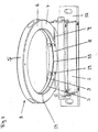
- the drawing shows a mounted on a terminal housing 2 Statorantennenring 1 for a telemetry system of a rotating torque-measuring device having a radially two-piece removable support ring 5 made of plastic, on the inner circumferential surface 8, a groove 9 is incorporated, in which a wire turn 10 of an induction coil. 3 is attached, which is also divided disassembled, wherein the stator antenna ring 1 with his flattened foot 4 is mounted on the terminal housing 2.
- the plastic carrier ring 5 of the stator antenna ring 1 is circular and has an inner diameter of preferably about 200 mm and an outer diameter of about 240 mm. But there are also sizes with an inner diameter of 100 to 300 mm executable.
- the ring cross-section 14 is preferably rectangular or square, but may also have a rounded or a round shape.
- the plastic carrier ring 5 is preferably made of polyamide PA 6, which acts simultaneously electrically insulating.
- a narrow groove 9 is recessed or milled approximately in the axial center of the inner circumferential surface 8, in which a single wire turn 10 of an induction coil 3 is fixed.
- the groove 9 is preferably milled as a dovetail groove, in which the wire turn 10 can be pressed in a form-fitting manner by a clip-in process, wherein it is flush with the inner circumferential surface 8.
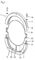
- Fig. 2 The design of the individual components of the stator antenna ring 1 without the connection housing 2 is in Fig. 2 the drawing shown in more detail. So shows Fig. 2 the drawing shows a radially two-part plastic carrier ring 5 as a carrier of the insulated introduced wire winding 10, which also according to the plastic ring parts consists of two radial sections 11, 12.
- the plastic carrier ring 5 consists of a horizontal upper portion 6 and a horizontal lower portion 7 with a flattened foot 4.
- the two horizontal sections 6, 7 have an angular range of 180 °, wherein the plastic support ring 5 also more and smaller Sections could be put together.
- the two illustrated sections 6, 7 are fastened together on a horizontal line by means of two screw connections, each consisting of a recessed in the subsection 7 threaded sleeve 15 and an inserted through a hole in the upper section 6 screw 16.
- the Statorantennenring 1 is screwed vertically vertically on the underlying terminal housing 2 vertically.
- a cable feedthrough is provided in the connection housing 2 in the middle under the foot part 4, where the two connecting wires 17 of the split wire winding 10 are inserted and connected to the dining and evaluation electronics located therein.
- the sole wire turn 10 of the induction coil 3 is also divided into equal sections 11, 12 as the plastic carrier ring 5.
- an upper wire winding section 11 of 180 ° is likewise clamped, at the two ends of which in each case a connecting shoe 13 is soldered.
- the lower wire winding section 12 divides into two equal sections, which are formed by the two connecting wires 17 guided in an insulated manner to the outside.
- a single wire turn is sufficient for measuring signal and measurement energy transmission, but it is also conceivable to provide a plurality of radially spaced wire windings 10 arranged parallel to one another, if this would be necessary for the transmission quality.
- the wire winding 10 is made of a copper material, which is formed as a round or flat wire to him simply and be able to claw reliably into the dovetail groove 9.
- connection housing 2 the two connecting wires 17 of the induction coil 3 are connected to the feed and evaluation electronics located therein to ensure the inductive transmission.
- the terminal housing 2 is formed as a flat cuboid housing body, which does not protrude into the free inner cross section of the stator antenna ring 1.
- two mounting plates 18 arranged alongside each other are also arranged, each having a bore, through which the stator antenna ring 1 can be screwed down to a stationary device part.
- stator antenna ring 1 For the function of the telemetry system, the stator antenna ring 1 must be arranged coaxially around a rotor antenna ring rotatable in the interior, leaving a small air gap between the two antenna parts. With such an antenna device, carrier-frequency supply and measuring voltages of a rotatable torque measuring shaft can then be transmitted.
Landscapes
- Engineering & Computer Science (AREA)
- Power Engineering (AREA)
- Arrangements For Transmission Of Measured Signals (AREA)
Description
- Die Erfindung betrifft einen Statorantennenring für ein induktives Telemetriesystem zur Messenergie- und Messwertübertragung.
- An rotierenden Maschinen ist es häufig notwendig, während des Betriebs mit geeigneten Aufnehmern rotierende Geräteteile zu überwachen oder daran belastungsrelevante Messwerte zu erfassen. Dazu werden insbesondere Drehmomente von rotierenden Wellen gemessen, bei denen die Drehmomentaufnehmer synchron mit der Welle umlaufen und das durch die Welle übertragene Drehmoment erfassen. Hierfür werden meist mit Dehnungsmessstreifen bestückte Drehmomentaufnehmer eingesetzt, die von stationären Geräteteilen mit Messenergie versorgt werden müssen und bei denen die gewonnenen Messsignale vom rotierenden Drehmomentaufnehmer wieder zu den stationären Geräteteilen übertragen werden. Zur berührungslosen Übertragung derartiger Messwerte und Messenergie können induktive Telemetriesysteme eingesetzt werden, die über ein rotierendes und ein stationäres Antennenteil verfügen. Dabei ist in jedem gegenüberliegend angeordneten Antennenteil mindestens eine Induktionsspule vorgesehen, wobei die Induktionsspulen induktiv über einen schmalen Luftspalt miteinander gekoppelt sind und so die elektrischen Signale berührungslos übertragen.
- Ein derartiges Telemetriesystem ist aus der
DE 10 2005 040 794 A1 bekannt, bei dem Messwerte von einem Rotor einer Gasturbine auf einen stationären Geräteteil und die notwendige Energie in umgekehrter Richtung berührungslos übertragen werden. Dazu ist am stationären Geräteteil ein Trägerring angeordnet, in dem isoliert eine Statorspule mit 10 Drahtwindungen befestigt ist. Die Drahtwindungen sind dabei in einer u-förmigen Nut angebracht und sind außerhalb des Trägerrings mit einem Wechselstromgenerator und einer Gleichspannungsquelle verbunden. Der Trägerring ist dabei als umlaufender Eisenkern ausgebildet, so dass die darin angeordneten Drahtwindungen der Induktionsspule isoliert angeordnet sein müssen. Axial gegenüberliegend zum Stator ist vor dem Trägerring der Rotor angeordnet. Am radial außen liegenden Rotorrand ist dabei ein auskragender Ringsteg angeflanscht, der koaxial in den Innenbereich des Statorantennenrings eintaucht und einen Rotorantennenring darstellt. An der inneren Mantelfläche des Rotorantennenrings ist eine Induktionsspule als Rotorspule angeordnet, die der Statorspule unter Belassung eines dünnen Luftspalts gegenübersteht. Die Rotorspule ist mit der am Rotor befestigten Messelektronik verbunden, so dass während des Rotorbetriebs die Messsignale und die Messenergie berührungslos übertragbar sind. Da bei diesem induktiven Telemetriesystem der Statorantennenring axial seitlich neben dem stationären Geräteteil und der Rotorantennenring offensichtlich am Ende der Rotorwelle befestigt ist, ist dieses Telemetriesystem nicht für axial durchgeführte Messwellensysteme geeignet. - In der
DE 10 2004 028 595 A1 ist eine Vorrichtung zum berührungslosen Übertragen von Energie und Daten zwischen einem feststehenden Bauteil und einem relativ rotatorisch zu diesem bewegbaren Bauteil beschrieben, wobei an jedem der beiden Bauteile ein eine Wicklung tragender Träger angeordnet ist und mindestens einer der beiden Träger teilbar ist. Die Spulendrähte der Wicklungen sind an den Trennstellen des Trägers nicht miteinander verbunden, sondern jeweils nur über ein Trägersegment geführt. - In der
US 4 939 400 A ist eine Vorrichtung zum berührungslosen Übertragen von Energie und Informationen zwischen einem feststehenden Bauteil und einem relativ rotatorisch zu diesem bewegbaren Bauteil beschrieben, bei der an jedem der beiden Bauteile ein eine Wicklung tragender Träger angeordnet ist und beide Träger teilbar sind. Die Spulendrähte der Wicklungen sind auch hier an den Trennstellen des jeweiligen Trägers nicht miteinander verbunden, sondern jeweils nur über ein Trägersegment geführt. - Der Erfindung liegt die Aufgabe zugrunde, einen Statorantennenring für ein induktives Telemetriesystem zu schaffen, das zur Drehmomentmessung an durchführbaren rotierenden Messwellen einsetzbar ist und das ohne großen Montageaufwand in das Messwellensystem leicht eingebaut werden kann oder auf einfache Weise austauschbar ist.
- Diese Aufgabe wird durch die im Patentanspruch 1 angegebene Erfindung gelöst. Weiterbildungen und vorteilhafte Ausführungsbeispiele der Erfindung sind in den Unteransprüchen angegeben.
- Die Erfindung hat den Vorteil, dass der radial teilbare Statorantennenring auf einfache Art auch bei montierten Messwellen nachträglich eingebaut oder ausgetauscht werden kann, ohne dass die Messwelle dafür demontiert werden müsste. Dabei hat die Ausführung mit einem Aufnahmering aus Kunststoffmaterial den Vorteil, dass die Induktionsspule gegenüber dem Stator nicht zusätzlich isoliert werden muss und auch sehr einfach herstellbar ist.
- Die Erfindung mit einer einzigen radial geteilten Drahtwindung hat zusätzlich den Vorteil, dass diese insbesondere durch die verdeckte Einlassung in den Kunststoffaufnahmering sehr robust und betriebssicher ist. Dabei hat insbesondere die Ausführung mit der Schwalbenschwanznut an der inneren Mantelfläche des Trägerrings den Vorteil, dass dadurch die Befestigung der Induktionsspule an dem Statorantennenring ohne Klebeprozesse einfach herstellbar ist.
- Die besondere Ausführungsart des Statorantennenrings aus einem Polyamidkunststoff hat weiterhin den Vorteil, dass dadurch ein sehr formstabiler und abmessungsgenauer Statorantennenring herstellbar ist. Dies hat zusätzlich noch den Vorteil, dass ein derartiger Statorantennenring nicht zusätzlich gegenüber den meist metallischen stationären Gehäuseteilen isoliert werden muss.
- Eine weitere besondere Ausführung der Erfindung, bei der der Kunststoffträgerring unmittelbar auf ein flaches Anschlussgehäuse montiert wird, hat den Vorteil, dass damit der Statorantennenring unmittelbar auf ein stationäres Geräteteil aufschraubbar ist und damit gleichzeitig die elektronische Anschluss- und Auswerteelektronik mechanisch geschützt untergebracht ist.
- Die Erfindung wird anhand eines Ausführungsbeispiels, das in der Zeichnung dargestellt ist, näher erläutert. Es zeigen:
- Fig. 1:
- einen auf einem Anschlussgehäuse montierten Statorantennenring; und
- Fig. 2:
- eine Seitenansicht eines demontierten Statorantennenrings.
- Die
Fig. 1 der Zeichnung zeigt einen auf einem Anschlussgehäuse 2 montierten Statorantennenring 1 für ein Telemetriesystem einer rotierenden Drehmoment-Messvorrichtung, der einen radial zweiteiligen demontierbaren Trägerring 5 aus Kunststoff aufweist, an dessen innerer Mantelfläche 8 eine Nut 9 eingearbeitet ist, in der eine Drahtwindung 10 einer Induktionsspule 3 befestigt ist, die ebenfalls demontierbar geteilt ist, wobei der Statorantennenring 1 mit seinem abgeflachten Fußteil 4 auf dem Anschlussgehäuse 2 befestigt ist. - Der Kunststoffträgerring 5 des Statorantennenrings 1 ist kreisförmig ausgebildet und besitzt einen Innendurchmesser von vorzugsweise ca. 200 mm und einen Außendurchmesser von ca. 240 mm. Es sind aber auch Baugrößen mit einem Innendurchmesser von 100 bis 300 mm ausführbar. Dabei ist der Ringquerschnitt 14 vorzugsweise rechteckig oder quadratisch, kann aber auch eine abgerundete oder eine runde Formgebung aufweisen. Der Kunststoffträgerring 5 besteht vorzugsweise aus Polyamid PA 6, das gleichzeitig elektrisch isolierend wirkt. In diesem Kunststoffring 5 ist etwa in der axialen Mitte der inneren Mantelfläche 8 eine schmale Nut 9 eingelassen oder eingefräst, in der eine einzige Drahtwindung 10 einer Induktionsspule 3 befestigt ist. Die Nut 9 ist dabei vorzugsweise als Schwalbenschwanznut eingefräst, in die die Drahtwindung 10 durch einen Einklippvorgang formschlüssig eindrückbar ist, wobei sie plan mit der inneren Mantelfläche 8 abschließt.
- Die Ausgestaltung der Einzelbestandteile des Statorantennenrings 1 ohne das Anschlussgehäuse 2 ist in
Fig. 2 der Zeichnung näher dargestellt. So zeigtFig. 2 der Zeichnung einen radial zweiteiligen Kunststoffträgerring 5 als Träger der isoliert eingebrachten Drahtwindung 10, die ebenfalls entsprechend der Kunststoffringteile aus zwei radialen Teilabschnitten 11, 12 besteht. Dadurch ist der Statorantennenring 1 auch bei einer durchgehenden rotierbaren Messwelle nachträglich anbaubar, ohne dass der betreffende Wellenabschnitt demontiert werden müsste. Deshalb besteht der Kunststoffträgerring 5 aus einem horizontalen Oberabschnitt 6 und einem horizontalen Unterabschnitt 7 mit einem abgeflachten Fußteil 4. Die beiden horizontalen Teilabschnitte 6, 7 weisen einen Winkelbereich von 180° auf, wobei der Kunststoffträgerring 5 auch aus mehr und kleineren Teilabschnitten zusammengesetzt werden könnte. Die beiden dargestellten Teilabschnitte 6, 7 werden auf einer horizontalen Linie mittels zweier Schraubverbindungen miteinander befestigt, die jeweils aus einer im Unterabschnitt 7 eingelassenen Gewindehülse 15 und einer durch eine Bohrung im Oberabschnitt 6 eingeführten Schraube 16 bestehen. - Am Fußteil 4 des Unterabschnitts 7 sind zusätzlich noch vier Bohrungen 19 eingelassen, durch die der Statorantennenring 1 horizontal auf dem darunterliegenden Anschlussgehäuse 2 vertikal senkrecht aufgeschraubt wird. Dabei ist in dem Anschlussgehäuse 2 in der Mitte unter dem Fußteil 4 eine Kabeldurchführung vorgesehen, wo die beiden Anschlussdrähte 17 der geteilten Drahtwindung 10 eingeführt und an der darin befindlichen Speise- und Auswerteelektronik angeschlossen sind. Zur Erleichterung der Montage bzw. Demontage des Statorantennenrings 1 ist die alleinige Drahtwindung 10 der Induktionsspule 3 ebenfalls in gleichgroße Teilabschnitte 11, 12 wie der Kunststoffträgerring 5 aufgeteilt. So ist in dem Oberabschnitt 6 des Kunststoffträgerrings 5 ebenfalls ein oberer Drahtwindungsabschnitt 11 von 180° eingeklemmt, an dessen beiden Enden jeweils ein Verbindungsschuh 13 angelötet ist. Dabei werden diese durch die Schraubverbindung 15, 16 mit den beiden Kabelschuhen 13 des unteren Drahtwindungsabschnitts 12 elektrisch verbunden. Der untere Drahtwindungsabschnitt 12 teilt sich wiederum in zwei gleich große Abschnitte, die durch die isoliert nach außen geführten beiden Anschlussdrähte 17 entstehen. Im Praxistest hat sich zwar herausgestellt, dass zur Messsignal- und Messenergieübertragung eine einzige Drahtwindung ausreicht, es ist aber auch denkbar, mehrere parallel nebeneinander angeordnete radial geteilte Drahtwindungen 10 vorzusehen, wenn dies für die Übertragungsgüte notwendig wäre. Wie bei Induktionsspulen 3 üblich, besteht die Drahtwindung 10 aus einem Kupferwerkstoff, der als Rund- oder Flachdraht ausgebildet ist, um ihn einfach und betriebssicher in die Schwalbenschwanznut 9 einklippen zu können.
- Im Anschlussgehäuse 2 werden die beiden Anschlussdrähte 17 der Induktionsspule 3 mit der darin befindlichen Speise- und Auswerteelektronik verbunden, um die induktive Übertragung zu gewährleisten. Dabei ist das Anschlussgehäuse 2 als flacher quaderförmiger Gehäusekörper ausgebildet, der nicht in den freien Innenquerschnitt des Statorantennenrings 1 hineinragt. Im Bodenbereich des Anschlussgehäuses 2 sind noch zwei längsseits angeordnete Befestigungsplatten 18 mit jeweils einer Bohrung angeordnet, durch die der Statorantennenring 1 nach unten an ein stationäres Geräteteil anschraubbar ist. Durch diese Bauart kann der Statorantennenring 1 auf einfache Art auch an durchgehende Wellensysteme montiert werden, indem er um eine rotierbare Drehmomentmesswelle eingebaut wird.
- Für die Funktion des Telemetriesystems muss der Statorantennenring 1 koaxial um einen im Innenraum rotierbaren Rotorantennenring unter Belassung eines geringen Luftspalts zwischen den beiden Antennenteilen angeordnet sein. Mit einer derartigen Antennenvorrichtung können dann trägerfrequente Speise- und Messspannungen einer rotierbaren Drehmomentmesswelle übertragen werden.
Claims (6)
- Statorantennenring (1) für ein Telemetriesystem zur Messwert- und Messenergieübertragung zwischen einem rotierbaren Messwertaufnehmer und einer stationären Gerätekomponente (2), wobei der Statorantennenring (1) aus einem Trägerring (5) mit einer Nut (9) und einer darin angeordneten Induktionsspule (3) besteht und an der stationären Gerätekomponente (2) befestigbar ist, wobei der Trägerring (5) aus mindestens zwei demontierbaren radialen Teilabschnitten (6, 7) aus einem isolierenden Kunststoffmaterial besteht, wobei in dem Trägerring (5) die Induktionsspule (3), die mindestens aus einer einzigen Drahtwindung (10) besteht, befestigt ist, dadurch gekennzeichnet, dass die Drahtwindung (10) gleichfalls aus zwei mit den Teilabschnitten (6, 7) demontierbaren radialen Drahtwindungsabschnitten (11, 12) besteht und dass die Drahtwindungsabschnitte (11, 12) zur Bildung der Drahtwindung (10) elektrisch verbunden sind.
- Statorantennenring (1) nach Anspruch 1, wobei der Trägerring (5) aus einem 180° umfassenden Oberabschnitt (6) und einem 180° umfassenden Unterabschnitt (7) besteht, die auf einer horizontalen Linie über eine demontierbare Schraubverbindung (15, 16) miteinander verbunden sind.
- Statorantennenring (1) nach Anspruch 1 oder 2, wobei der Oberabschnitt (6) des Trägerrings (5) einen gleichbleibenden quadratischen oder rechteckigen Ringquerschnitt (14) aufweist und auf der inneren Mantelfläche (8) des Oberabschnitts (6) eine umlaufende schwalbenschwanzförmige Nut (9) eingelassen ist, in der als Teilabschnitt ein oberer Drahtwindungsabschnitt (11) eingeklippt befestigt ist.
- Statorantennenring (1) nach Anspruch 3, wobei der Unterabschnitt (7) des Trägerrings (5) einen gleichbleibenden quadratischen oder rechteckigen Ringquerschnitt (14) aufweist, der Unterabschnitt (7) an seinem Fußteil (4) horizontal eben abgeflacht ist und in der inneren Mantelfläche (8) des Unterabschnitts (7) eine umlaufende schwalbenschwanzförmige Nut (9) eingelassen ist, in der als Teilabschnitt ein unterer Drahtwindungsabschnitt (12) eingeklippt befestigt ist, dessen Anschlussdrähte (17) über eine vertikale Bohrung im Fußteil (4) isoliert voneinander senkrecht nach außen geführt sind.
- Statorantennenring (1) nach einem der vorhergehenden Ansprüche, wobei der Unterabschnitt (7) des Trägerrings (5) mit seinem Fußteil (4) auf einem horizontal angeordneten Anschlussgehäuse (2) befestigbar ist und in dessen Innenraum die Anschlussdrähte (17) der Induktionsspule (3) mit einer darin angeordneten Speise- und Auswerteelektronik verbindbar sind.
- Statorantennenring (1) nach einem der vorhergehenden Ansprüche, wobei jeder der beiden Drahtwindungsabschnitte (11, 12) aus einem runden oder flachen Kupferdraht besteht, der bündig mit der inneren Mantelfläche (8) des Teilabschnitts (6, 7) des Trägerrings (5) abschließt und an dessen Enden jeweils ein Verbindungsschuh (13) horizontal abknickend befestigt ist, der über eine Schraubverbindung (15, 16) mit dem gegenüberliegenden Drahtwindungsabschnitt (11, 12) verbunden ist.
Applications Claiming Priority (1)
| Application Number | Priority Date | Filing Date | Title |
|---|---|---|---|
| DE200810021775 DE102008021775B4 (de) | 2008-04-30 | 2008-04-30 | Statorantennenring |
Publications (3)
| Publication Number | Publication Date |
|---|---|
| EP2113930A2 EP2113930A2 (de) | 2009-11-04 |
| EP2113930A3 EP2113930A3 (de) | 2013-06-26 |
| EP2113930B1 true EP2113930B1 (de) | 2019-03-27 |
Family
ID=40796302
Family Applications (1)
| Application Number | Title | Priority Date | Filing Date |
|---|---|---|---|
| EP09005984.1A Active EP2113930B1 (de) | 2008-04-30 | 2009-04-30 | Statorantennenring |
Country Status (2)
| Country | Link |
|---|---|
| EP (1) | EP2113930B1 (de) |
| DE (1) | DE102008021775B4 (de) |
Families Citing this family (3)
| Publication number | Priority date | Publication date | Assignee | Title |
|---|---|---|---|---|
| JP6995941B1 (ja) * | 2020-07-07 | 2022-01-17 | 日本航空電子工業株式会社 | 無線コネクタ着脱方法、ロボット装置、無線コネクタ及び無線コネクタユニット |
| CN112290191B (zh) * | 2020-11-21 | 2025-07-15 | 西安热工研究院有限公司 | 一种适用于叶片动应力/动频率测试的天线环装置 |
| EP4266485A1 (de) * | 2022-04-19 | 2023-10-25 | Flender GmbH | Statorantennen-einheit für eine messanordnung |
Family Cites Families (3)
| Publication number | Priority date | Publication date | Assignee | Title |
|---|---|---|---|---|
| JPH01212131A (ja) * | 1988-02-19 | 1989-08-25 | Nippon Syst Kenkyusho:Kk | 分割コイル型同軸カプラを用いた伝送装置 |
| DE102004028595A1 (de) * | 2004-06-12 | 2005-12-29 | Daimlerchrysler Ag | Vorrichtung zum berührungslosen induktiven Übertragen von Energie und Daten und ein damit ausgestattetes Kraftfahrzeugmodul |
| DE102005040794A1 (de) | 2004-09-09 | 2006-04-06 | Alstom Technology Ltd | Telemetriesystem für die Datenübermittlung, insbesondere zwischen dem rotierenden und dem stationären Teil einer Gasturbine |
-
2008
- 2008-04-30 DE DE200810021775 patent/DE102008021775B4/de not_active Expired - Fee Related
-
2009
- 2009-04-30 EP EP09005984.1A patent/EP2113930B1/de active Active
Non-Patent Citations (1)
| Title |
|---|
| None * |
Also Published As
| Publication number | Publication date |
|---|---|
| EP2113930A3 (de) | 2013-06-26 |
| DE102008021775B4 (de) | 2012-06-28 |
| DE102008021775A1 (de) | 2009-11-05 |
| EP2113930A2 (de) | 2009-11-04 |
Similar Documents
| Publication | Publication Date | Title |
|---|---|---|
| EP1927823B1 (de) | Drehgeber | |
| EP1927824B1 (de) | Drehgeber | |
| DE102011075548A1 (de) | Lager mit einer Energieerfassungseinheit, insbesondere Pendelrollen-Lager zur Lagerung einer Walze | |
| DE112015005614T5 (de) | Drehwinkelermittlungsvorrichtung und Servolenkungsvorrichtung | |
| WO2015067497A2 (de) | Elektromaschine | |
| DE112016007430T5 (de) | Stator einer elektrischen Drehmaschine und Herstellungsverfahren dafür | |
| DE102008021775B4 (de) | Statorantennenring | |
| DE10161740B4 (de) | Schleifringübertrager | |
| EP3890899A1 (de) | Erfassen und übertragen von daten eines lagers eines stahl- oder walzwerks | |
| DE102010053339B4 (de) | Umdrehungswinkelsensor | |
| DE102007020940B3 (de) | Vorrichtung zum Erkennen und Überwachen von Schäden bei Wälzlagern | |
| DE102009040106A1 (de) | Schleifringvorrichtung | |
| EP3839462A1 (de) | Zahnriemen mit integrierter sensorik | |
| WO2020126820A1 (de) | Motoranordnung mit sensormodul | |
| EP4174463B1 (de) | System zur erfassung von drehmoment und drehwinkel | |
| DE102013224836A1 (de) | Hydrodynamische Maschine mit Messsystem | |
| DE102005040794A1 (de) | Telemetriesystem für die Datenübermittlung, insbesondere zwischen dem rotierenden und dem stationären Teil einer Gasturbine | |
| EP4249855B1 (de) | Drehgeber und verfahren zum betrieb eines drehgebers | |
| DE102012016912A1 (de) | Platine zur Verwendung in einer elektrischen Maschine, insbesondere in einem Elektromotor, vorzugsweise einem Außenläufermotor, sowie elektrische Maschine mit einer solchen Platine | |
| DE102024111300B4 (de) | Sensoranordnung an einer elektrischen Maschine und Aktuator für eine steer-by-wire-Anordnung | |
| WO2009021904A1 (de) | Elektrische maschine mit einer vorrichtung zur befestigung eines stators | |
| DE102016222925A1 (de) | Schleifringeinheit | |
| DE102009035368A1 (de) | Rotierende elektrische Vorrichtung für Fahrzeuge | |
| DE102004026476A1 (de) | Vorrichtung zur rotativen Winkelmessung | |
| DE102014212510A1 (de) | Haltekörper für einen ringförmigen Hochspannungs-Stromwandler und Stromwandler-Messanordnung |
Legal Events
| Date | Code | Title | Description |
|---|---|---|---|
| PUAI | Public reference made under article 153(3) epc to a published international application that has entered the european phase |
Free format text: ORIGINAL CODE: 0009012 |
|
| AK | Designated contracting states |
Kind code of ref document: A2 Designated state(s): AT BE BG CH CY CZ DE DK EE ES FI FR GB GR HR HU IE IS IT LI LT LU LV MC MK MT NL NO PL PT RO SE SI SK TR |
|
| PUAL | Search report despatched |
Free format text: ORIGINAL CODE: 0009013 |
|
| AK | Designated contracting states |
Kind code of ref document: A3 Designated state(s): AT BE BG CH CY CZ DE DK EE ES FI FR GB GR HR HU IE IS IT LI LT LU LV MC MK MT NL NO PL PT RO SE SI SK TR |
|
| AX | Request for extension of the european patent |
Extension state: AL BA RS |
|
| RIC1 | Information provided on ipc code assigned before grant |
Ipc: H01F 38/18 20060101AFI20130522BHEP |
|
| 17P | Request for examination filed |
Effective date: 20131224 |
|
| RBV | Designated contracting states (corrected) |
Designated state(s): AT BE BG CH CY CZ DE DK EE ES FI FR GB GR HR HU IE IS IT LI LT LU LV MC MK MT NL NO PL PT RO SE SI SK TR |
|
| STAA | Information on the status of an ep patent application or granted ep patent |
Free format text: STATUS: EXAMINATION IS IN PROGRESS |
|
| 17Q | First examination report despatched |
Effective date: 20171107 |
|
| GRAP | Despatch of communication of intention to grant a patent |
Free format text: ORIGINAL CODE: EPIDOSNIGR1 |
|
| STAA | Information on the status of an ep patent application or granted ep patent |
Free format text: STATUS: GRANT OF PATENT IS INTENDED |
|
| INTG | Intention to grant announced |
Effective date: 20181001 |
|
| GRAS | Grant fee paid |
Free format text: ORIGINAL CODE: EPIDOSNIGR3 |
|
| GRAA | (expected) grant |
Free format text: ORIGINAL CODE: 0009210 |
|
| STAA | Information on the status of an ep patent application or granted ep patent |
Free format text: STATUS: THE PATENT HAS BEEN GRANTED |
|
| AK | Designated contracting states |
Kind code of ref document: B1 Designated state(s): AT BE BG CH CY CZ DE DK EE ES FI FR GB GR HR HU IE IS IT LI LT LU LV MC MK MT NL NO PL PT RO SE SI SK TR |
|
| REG | Reference to a national code |
Ref country code: GB Ref legal event code: FG4D Free format text: NOT ENGLISH |
|
| REG | Reference to a national code |
Ref country code: CH Ref legal event code: EP |
|
| REG | Reference to a national code |
Ref country code: AT Ref legal event code: REF Ref document number: 1114013 Country of ref document: AT Kind code of ref document: T Effective date: 20190415 |
|
| REG | Reference to a national code |
Ref country code: DE Ref legal event code: R082 Ref document number: 502009015673 Country of ref document: DE Representative=s name: STAUDTE, RALPH, DIPL.-ING., DE Ref country code: IE Ref legal event code: FG4D Free format text: LANGUAGE OF EP DOCUMENT: GERMAN |
|
| REG | Reference to a national code |
Ref country code: DE Ref legal event code: R096 Ref document number: 502009015673 Country of ref document: DE |
|
| PG25 | Lapsed in a contracting state [announced via postgrant information from national office to epo] |
Ref country code: SE Free format text: LAPSE BECAUSE OF FAILURE TO SUBMIT A TRANSLATION OF THE DESCRIPTION OR TO PAY THE FEE WITHIN THE PRESCRIBED TIME-LIMIT Effective date: 20190327 Ref country code: FI Free format text: LAPSE BECAUSE OF FAILURE TO SUBMIT A TRANSLATION OF THE DESCRIPTION OR TO PAY THE FEE WITHIN THE PRESCRIBED TIME-LIMIT Effective date: 20190327 Ref country code: NO Free format text: LAPSE BECAUSE OF FAILURE TO SUBMIT A TRANSLATION OF THE DESCRIPTION OR TO PAY THE FEE WITHIN THE PRESCRIBED TIME-LIMIT Effective date: 20190627 Ref country code: LT Free format text: LAPSE BECAUSE OF FAILURE TO SUBMIT A TRANSLATION OF THE DESCRIPTION OR TO PAY THE FEE WITHIN THE PRESCRIBED TIME-LIMIT Effective date: 20190327 |
|
| REG | Reference to a national code |
Ref country code: NL Ref legal event code: MP Effective date: 20190327 |
|
| PG25 | Lapsed in a contracting state [announced via postgrant information from national office to epo] |
Ref country code: HR Free format text: LAPSE BECAUSE OF FAILURE TO SUBMIT A TRANSLATION OF THE DESCRIPTION OR TO PAY THE FEE WITHIN THE PRESCRIBED TIME-LIMIT Effective date: 20190327 Ref country code: GR Free format text: LAPSE BECAUSE OF FAILURE TO SUBMIT A TRANSLATION OF THE DESCRIPTION OR TO PAY THE FEE WITHIN THE PRESCRIBED TIME-LIMIT Effective date: 20190628 Ref country code: LV Free format text: LAPSE BECAUSE OF FAILURE TO SUBMIT A TRANSLATION OF THE DESCRIPTION OR TO PAY THE FEE WITHIN THE PRESCRIBED TIME-LIMIT Effective date: 20190327 Ref country code: NL Free format text: LAPSE BECAUSE OF FAILURE TO SUBMIT A TRANSLATION OF THE DESCRIPTION OR TO PAY THE FEE WITHIN THE PRESCRIBED TIME-LIMIT Effective date: 20190327 Ref country code: BG Free format text: LAPSE BECAUSE OF FAILURE TO SUBMIT A TRANSLATION OF THE DESCRIPTION OR TO PAY THE FEE WITHIN THE PRESCRIBED TIME-LIMIT Effective date: 20190627 |
|
| PG25 | Lapsed in a contracting state [announced via postgrant information from national office to epo] |
Ref country code: IT Free format text: LAPSE BECAUSE OF FAILURE TO SUBMIT A TRANSLATION OF THE DESCRIPTION OR TO PAY THE FEE WITHIN THE PRESCRIBED TIME-LIMIT Effective date: 20190327 Ref country code: ES Free format text: LAPSE BECAUSE OF FAILURE TO SUBMIT A TRANSLATION OF THE DESCRIPTION OR TO PAY THE FEE WITHIN THE PRESCRIBED TIME-LIMIT Effective date: 20190327 Ref country code: RO Free format text: LAPSE BECAUSE OF FAILURE TO SUBMIT A TRANSLATION OF THE DESCRIPTION OR TO PAY THE FEE WITHIN THE PRESCRIBED TIME-LIMIT Effective date: 20190327 Ref country code: CZ Free format text: LAPSE BECAUSE OF FAILURE TO SUBMIT A TRANSLATION OF THE DESCRIPTION OR TO PAY THE FEE WITHIN THE PRESCRIBED TIME-LIMIT Effective date: 20190327 Ref country code: EE Free format text: LAPSE BECAUSE OF FAILURE TO SUBMIT A TRANSLATION OF THE DESCRIPTION OR TO PAY THE FEE WITHIN THE PRESCRIBED TIME-LIMIT Effective date: 20190327 Ref country code: PT Free format text: LAPSE BECAUSE OF FAILURE TO SUBMIT A TRANSLATION OF THE DESCRIPTION OR TO PAY THE FEE WITHIN THE PRESCRIBED TIME-LIMIT Effective date: 20190727 Ref country code: SK Free format text: LAPSE BECAUSE OF FAILURE TO SUBMIT A TRANSLATION OF THE DESCRIPTION OR TO PAY THE FEE WITHIN THE PRESCRIBED TIME-LIMIT Effective date: 20190327 |
|
| PG25 | Lapsed in a contracting state [announced via postgrant information from national office to epo] |
Ref country code: PL Free format text: LAPSE BECAUSE OF FAILURE TO SUBMIT A TRANSLATION OF THE DESCRIPTION OR TO PAY THE FEE WITHIN THE PRESCRIBED TIME-LIMIT Effective date: 20190327 |
|
| REG | Reference to a national code |
Ref country code: CH Ref legal event code: PL |
|
| REG | Reference to a national code |
Ref country code: BE Ref legal event code: MM Effective date: 20190430 |
|
| PG25 | Lapsed in a contracting state [announced via postgrant information from national office to epo] |
Ref country code: LU Free format text: LAPSE BECAUSE OF NON-PAYMENT OF DUE FEES Effective date: 20190430 Ref country code: IS Free format text: LAPSE BECAUSE OF FAILURE TO SUBMIT A TRANSLATION OF THE DESCRIPTION OR TO PAY THE FEE WITHIN THE PRESCRIBED TIME-LIMIT Effective date: 20190727 |
|
| REG | Reference to a national code |
Ref country code: DE Ref legal event code: R097 Ref document number: 502009015673 Country of ref document: DE |
|
| PG25 | Lapsed in a contracting state [announced via postgrant information from national office to epo] |
Ref country code: MC Free format text: LAPSE BECAUSE OF FAILURE TO SUBMIT A TRANSLATION OF THE DESCRIPTION OR TO PAY THE FEE WITHIN THE PRESCRIBED TIME-LIMIT Effective date: 20190327 Ref country code: CH Free format text: LAPSE BECAUSE OF NON-PAYMENT OF DUE FEES Effective date: 20190430 Ref country code: LI Free format text: LAPSE BECAUSE OF NON-PAYMENT OF DUE FEES Effective date: 20190430 Ref country code: DK Free format text: LAPSE BECAUSE OF FAILURE TO SUBMIT A TRANSLATION OF THE DESCRIPTION OR TO PAY THE FEE WITHIN THE PRESCRIBED TIME-LIMIT Effective date: 20190327 |
|
| PLBE | No opposition filed within time limit |
Free format text: ORIGINAL CODE: 0009261 |
|
| STAA | Information on the status of an ep patent application or granted ep patent |
Free format text: STATUS: NO OPPOSITION FILED WITHIN TIME LIMIT |
|
| GBPC | Gb: european patent ceased through non-payment of renewal fee |
Effective date: 20190627 |
|
| PG25 | Lapsed in a contracting state [announced via postgrant information from national office to epo] |
Ref country code: SI Free format text: LAPSE BECAUSE OF FAILURE TO SUBMIT A TRANSLATION OF THE DESCRIPTION OR TO PAY THE FEE WITHIN THE PRESCRIBED TIME-LIMIT Effective date: 20190327 Ref country code: BE Free format text: LAPSE BECAUSE OF NON-PAYMENT OF DUE FEES Effective date: 20190430 |
|
| 26N | No opposition filed |
Effective date: 20200103 |
|
| PG25 | Lapsed in a contracting state [announced via postgrant information from national office to epo] |
Ref country code: TR Free format text: LAPSE BECAUSE OF FAILURE TO SUBMIT A TRANSLATION OF THE DESCRIPTION OR TO PAY THE FEE WITHIN THE PRESCRIBED TIME-LIMIT Effective date: 20190327 |
|
| PG25 | Lapsed in a contracting state [announced via postgrant information from national office to epo] |
Ref country code: GB Free format text: LAPSE BECAUSE OF NON-PAYMENT OF DUE FEES Effective date: 20190627 Ref country code: IE Free format text: LAPSE BECAUSE OF NON-PAYMENT OF DUE FEES Effective date: 20190430 |
|
| PG25 | Lapsed in a contracting state [announced via postgrant information from national office to epo] |
Ref country code: FR Free format text: LAPSE BECAUSE OF NON-PAYMENT OF DUE FEES Effective date: 20190527 |
|
| REG | Reference to a national code |
Ref country code: AT Ref legal event code: MM01 Ref document number: 1114013 Country of ref document: AT Kind code of ref document: T Effective date: 20190430 |
|
| PG25 | Lapsed in a contracting state [announced via postgrant information from national office to epo] |
Ref country code: AT Free format text: LAPSE BECAUSE OF NON-PAYMENT OF DUE FEES Effective date: 20190430 |
|
| REG | Reference to a national code |
Ref country code: DE Ref legal event code: R082 Ref document number: 502009015673 Country of ref document: DE Representative=s name: STAUDTE, RALPH, DIPL.-ING., DE Ref country code: DE Ref legal event code: R081 Ref document number: 502009015673 Country of ref document: DE Owner name: HOTTINGER BRUEEL & KJAER GMBH, DE Free format text: FORMER OWNER: HOTTINGER BALDWIN MESSTECHNIK GMBH, 64293 DARMSTADT, DE |
|
| PG25 | Lapsed in a contracting state [announced via postgrant information from national office to epo] |
Ref country code: CY Free format text: LAPSE BECAUSE OF FAILURE TO SUBMIT A TRANSLATION OF THE DESCRIPTION OR TO PAY THE FEE WITHIN THE PRESCRIBED TIME-LIMIT Effective date: 20190327 |
|
| PG25 | Lapsed in a contracting state [announced via postgrant information from national office to epo] |
Ref country code: HU Free format text: LAPSE BECAUSE OF FAILURE TO SUBMIT A TRANSLATION OF THE DESCRIPTION OR TO PAY THE FEE WITHIN THE PRESCRIBED TIME-LIMIT; INVALID AB INITIO Effective date: 20090430 Ref country code: MT Free format text: LAPSE BECAUSE OF FAILURE TO SUBMIT A TRANSLATION OF THE DESCRIPTION OR TO PAY THE FEE WITHIN THE PRESCRIBED TIME-LIMIT Effective date: 20190327 |
|
| PG25 | Lapsed in a contracting state [announced via postgrant information from national office to epo] |
Ref country code: MK Free format text: LAPSE BECAUSE OF FAILURE TO SUBMIT A TRANSLATION OF THE DESCRIPTION OR TO PAY THE FEE WITHIN THE PRESCRIBED TIME-LIMIT Effective date: 20190327 |
|
| P01 | Opt-out of the competence of the unified patent court (upc) registered |
Effective date: 20230606 |
|
| PGFP | Annual fee paid to national office [announced via postgrant information from national office to epo] |
Ref country code: DE Payment date: 20250319 Year of fee payment: 17 |