EP2113824A2 - Steuervorrichtung mit haptischer Rückmeldung - Google Patents
Steuervorrichtung mit haptischer Rückmeldung Download PDFInfo
- Publication number
- EP2113824A2 EP2113824A2 EP09158573A EP09158573A EP2113824A2 EP 2113824 A2 EP2113824 A2 EP 2113824A2 EP 09158573 A EP09158573 A EP 09158573A EP 09158573 A EP09158573 A EP 09158573A EP 2113824 A2 EP2113824 A2 EP 2113824A2
- Authority
- EP
- European Patent Office
- Prior art keywords
- armature
- plate
- control device
- fixed part
- coils
- Prior art date
- Legal status (The legal status is an assumption and is not a legal conclusion. Google has not performed a legal analysis and makes no representation as to the accuracy of the status listed.)
- Withdrawn
Links
Images
Classifications
-
- G—PHYSICS
- G06—COMPUTING; CALCULATING OR COUNTING
- G06F—ELECTRIC DIGITAL DATA PROCESSING
- G06F3/00—Input arrangements for transferring data to be processed into a form capable of being handled by the computer; Output arrangements for transferring data from processing unit to output unit, e.g. interface arrangements
- G06F3/01—Input arrangements or combined input and output arrangements for interaction between user and computer
- G06F3/016—Input arrangements with force or tactile feedback as computer generated output to the user
-
- H—ELECTRICITY
- H01—ELECTRIC ELEMENTS
- H01H—ELECTRIC SWITCHES; RELAYS; SELECTORS; EMERGENCY PROTECTIVE DEVICES
- H01H2215/00—Tactile feedback
- H01H2215/05—Tactile feedback electromechanical
-
- H—ELECTRICITY
- H01—ELECTRIC ELEMENTS
- H01H—ELECTRIC SWITCHES; RELAYS; SELECTORS; EMERGENCY PROTECTIVE DEVICES
- H01H2239/00—Miscellaneous
- H01H2239/074—Actuation by finger touch
Definitions
- the present invention relates to a haptic feedback control device comprising a support plate capable of transmitting a haptic feedback, such as a vibration, to a user for example after the modification or selection of a command.
- a haptic feedback control device comprising a support plate capable of transmitting a haptic feedback, such as a vibration, to a user for example after the modification or selection of a command.
- haptic feedback control devices comprising vibrators (such as "voice coil” type vibrators) in which a magnet slides inside a coil to transmit a vibration to a tactile surface of the device. .
- control devices including an actuator in which an armature slides between two coils.
- the alternate feeding of the coils makes it possible to attract the armature towards one or the other of the coils, thus creating a vibration oscillating effect.
- These known devices comprise fixing means for attaching the armature to a support plate of the device forming the tactile surface, so as to transmit a haptic feedback to a user.
- the armature is for example fixed to the support plate by screwing or snap-fastening.
- the assembly of the means for fixing the armature with those corresponding to the support plate may cause mounting difficulties, especially when the support plate must be assembled to a plurality of actuators.
- these fixing means may cause changes in the vibrations produced by the actuators, the fixing means being able to absorb a portion of the energy to be transmitted to the support plate and / or modify the frequencies of the generated haptic feedback.
- the object of the present invention is therefore to provide a robust haptic feedback control device, easy to assemble and which does not have the drawbacks of the state of the art.
- the subject of the invention is a haptic feedback control device comprising a support plate having a tactile surface sensor for transmitting a haptic feedback to a user and at least one actuator connected to said plate to generate the haptic feedback, said actuator comprising a fixed part and an armature movable in translation in a gap of the fixed part between a first and a second position, characterized in that said plate and said armature are formed in one piece.
- the invention relates to a haptic feedback control device, such as a keyboard or a touch screen, which can transmit a haptic feedback to a user having, for example, modified or selected a command.
- a haptic feedback control device such as a keyboard or a touch screen
- the device comprises at least one actuator for generating a haptic feedback and a support plate connected to the actuator for transmitting the generated haptic feedback to a user.
- the haptic feedback is for example vibratory type.
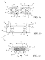
- device 1 comprising two actuators 2 and a support plate 4.
- the support plate 4 comprises a tactile surface sensor ("touchpad” in English) fixed on said plate 4 for example by gluing and advantageously covered by a protective skin (not shown).
- tactile surfaces of planar shape, make it possible to detect a simple support of the finger and / or a displacement of this support on the surface.
- the touch surface sensor uses, for example, pressure-sensitive resistors (also known as the FSR sensor for "Force Sensing Resistor”).
- the sensor comprises a semiconductor layer sandwiched between for example a conductive layer and a resistive layer.
- the touch sensor comprises two flexible support sheets spaced from each other by elastic spacers and on mutually opposite faces of the elements making it possible to make an electrical contact during the compression. of the sensor.
- Each actuator 2 comprises a fixed part 6 and a movable armature 8 in translation in an air gap E of the fixed part 6 between a first and a second position, parallel to a longitudinal axis I of the armature 8 ( figure 1c ).
- the gap E is about 0.5 millimeters.
- the control device 1 advantageously comprises a frame 10 for housing the actuators 2 and supporting the support plate 4 ( figure 1b ).
- the frame 10 advantageously comprises a holding means 12 of the plate 4 to the frame 10, so as to allow the displacement of the plate 4 along the longitudinal axis I of the armature 8.
- the holding means 12 is advantageously formed in borders parallel to the direction of displacement D of the support plate 4 ( figure 1c ).
- the holding means 12 is formed by two opposite edges 14 of the plate 4 each having a bulge 14 engaging in a corresponding slide 15 of the frame 10, as shown in FIG. figure 1b .
- the slide 15 is formed by two elastic lips, pinching the corresponding bulge 14 of the plate 4.
- the holding means 12 enables the control device 1 to withstand high pressures perpendicular to the surface of the support plate 4, while limiting the noise resulting from the movements of the plate 4 relative to the frame 10.
- each actuator 2 comprises two electromagnetic coils 17, 18.
- the armature 8 is formed in a face opposite to a tactile surface of the plate 4.
- the armature 8 is formed by a lateral extension of the plate 4.
- the coils 17, 18 are arranged around a longitudinal axis I of the armature 8 and are able to provide a magnetic field when they are powered so that in operation, the magnetic field created by the coils 17, 18 directs the armature 8 alternately towards one or the other of the coils 17, 18.
- the coils 17, 18 are fixed in an annular housing of an armature of the fixed part 6 and the armature 8 has a corresponding shape adapted to assemble with the armature of the fixed part 6 and the coils 17 , 18, while leaving a gap to form the air gap E ( figures 1c and 2d ) of the actuator 2.
- the plate 4 and the armature 8 are formed in one piece.
- the arrangement of the plate and the actuator makes it possible, on the one hand, for the displacement of the armature 8 in the fixed part 6 to vibrate the support plate 4 and, on the other hand, that the armature 8 and therefore the plate 4, are mechanically held together robustly.
- the plate 4 is advantageously made of non-magnetic material, for example aluminum.
- a plastic support plate 4 and it is expected that a portion of the plate 4 forming the armature 8, comprises a metal sleeve (not shown).
- the plate 4 and the armature 8 can then easily be obtained by molding and the sliding of the armature 8 in the fixed part 6 is guaranteed by the metal sleeve.
- the actuators 2 do not need to be perfectly aligned with the plate 4 to be assembled thereto, which facilitates and reduces assembly time.
- the distribution of the actuators 2 on the support plate 4 is facilitated, which optimizes the arrangement of the actuators 2 to obtain a uniform feeling by the user on the entire support plate 4.
- the energy losses are limited because the vibration frequencies and amplitudes are not deformed or diminished by intermediate parts or by possible loosening of the fastening means.
- At least one damper 20 is provided between the armature 8 and the fixed part 6.
- the actuator 2 has two dampers 20, each having for example a crown shape, as can be distinguished on the figure 1c .
- the coils 17, 18 are alternately energized so that during a first period, a first magnetic field B1 attracts the armature 8 to the first coil 17 in a first position ( figures 1c and 2d ).
- the first magnetic field lines B1 will preferentially buckle in the part of the armature 8 on which the first coil 17 is mounted and in the fixed part 6.
- a second magnetic field attracts the armature 8 to the second coil 18, in a second direction opposite to the first direction.
- the second magnetic field lines will preferentially buckle in the part of the armature 8 on which is mounted the second coil 18 and in the fixed part 6.
- the armature 8, and therefore the support plate 4 then move alternately in the two opposite directions, thus creating a vibration-like haptic effect at the plate 4 along the arrow D, parallel to the longitudinal axis I of the armature 8 ( figures 1c and 2d ).
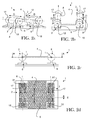
- the device 1 comprises at least one actuator 2 having an electromagnetic coil 17 arranged around the armature 8.
- the fixed part 6 is held in the frame 10 by a connecting washer 22 having a bracket.
- the armature 8 is advantageously formed by an end of an arm 24 of the plate 4.
- the arm 24 has a base originating in a face of the plate 4 opposite a touch surface of the plate 4 or may be formed by a lateral extension of the plate 4.
- the arm 24 has a bend, so that an axis longitudinal I of the armature 8 is parallel to a plane defined by the plate 4.
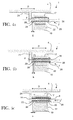
- a base of the arm 24 originates from a central dimension of the support plate 1, in the middle of a lateral axis of the plate 4 ( Figures 4a and 4b ).
- the fixed part 6 comprises a first stop formed by a bend of the arm 24 in a first position and a second stop 26 formed by a fixing washer, such as a nut, fixed to the end of the arm 24 of the plate 4 in a second position.
- the plate 4 is preferably metal or plastic with a metal sleeve 16 surrounding the armature 8, as best seen on the Figure 4b and 4c .
- the fixed part 6 preferably comprises a slider 28 to further improve the sliding of the armature 8 in the fixed part 6.
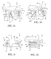
- the coil 17 is alternately energized so that during a first period, the armature 8 is attracted to the first stop formed by the elbow of the arm 24.
- the magnetic field lines created will preferentially close in the part armature 8 opposite the first stop.
- the armature 8 is attracted to the second stop 26 of the fixed part 6 in a second direction opposite to the first direction.
- the lines created magnetic field preferentially buckle in the armature portion 8 facing the second stop 26.
- the armature 8, and therefore the support plate 4 then move alternately in both directions, thus creating a vibration-like haptic effect at the plate 4 along the arrow D, parallel to the longitudinal axis I of the induced 8 ( figure 3d , 4a, 4b and 4c ).
- Such a control device 1 thus makes it possible to provide a haptic effect to a user by oscillating the armature 8 in the fixed part 6, without loss of efficiency, with a simple control device 1 to be produced and assembled.
Applications Claiming Priority (1)
| Application Number | Priority Date | Filing Date | Title |
|---|---|---|---|
| FR0802322A FR2930656B1 (fr) | 2008-04-25 | 2008-04-25 | Dispositif de commande a retour haptique |
Publications (2)
| Publication Number | Publication Date |
|---|---|
| EP2113824A2 true EP2113824A2 (de) | 2009-11-04 |
| EP2113824A3 EP2113824A3 (de) | 2016-05-18 |
Family
ID=40060309
Family Applications (1)
| Application Number | Title | Priority Date | Filing Date |
|---|---|---|---|
| EP09158573.7A Withdrawn EP2113824A3 (de) | 2008-04-25 | 2009-04-23 | Steuervorrichtung mit haptischer Rückmeldung |
Country Status (2)
| Country | Link |
|---|---|
| EP (1) | EP2113824A3 (de) |
| FR (1) | FR2930656B1 (de) |
Cited By (2)
| Publication number | Priority date | Publication date | Assignee | Title |
|---|---|---|---|---|
| FR2944613A1 (fr) * | 2009-04-20 | 2010-10-22 | Dav | Dispositif de commande a retour haptique |
| WO2023002129A1 (fr) * | 2021-07-22 | 2023-01-26 | Novares France | Actionneur oscillant destiné à générer une vibration haptique |
Family Cites Families (5)
| Publication number | Priority date | Publication date | Assignee | Title |
|---|---|---|---|---|
| FR2778267B1 (fr) * | 1998-04-30 | 2000-07-21 | Otis Elevator Co | Bouton d'appel d'ascenseur pour non-voyants |
| US6822635B2 (en) * | 2000-01-19 | 2004-11-23 | Immersion Corporation | Haptic interface for laptop computers and other portable devices |
| DE10243600A1 (de) * | 2002-09-19 | 2004-04-01 | Delphi Technologies, Inc., Troy | Elektrischer Schalter |
| US7825903B2 (en) * | 2005-05-12 | 2010-11-02 | Immersion Corporation | Method and apparatus for providing haptic effects to a touch panel |
| DE202006011302U1 (de) * | 2006-07-22 | 2006-09-21 | Hoffmann & Krippner Gmbh | Tastatur |
-
2008
- 2008-04-25 FR FR0802322A patent/FR2930656B1/fr active Active
-
2009
- 2009-04-23 EP EP09158573.7A patent/EP2113824A3/de not_active Withdrawn
Cited By (4)
| Publication number | Priority date | Publication date | Assignee | Title |
|---|---|---|---|---|
| FR2944613A1 (fr) * | 2009-04-20 | 2010-10-22 | Dav | Dispositif de commande a retour haptique |
| EP2244167A3 (de) * | 2009-04-20 | 2017-03-29 | Dav | Steuervorrichtung mit haptischer Rückmeldung |
| WO2023002129A1 (fr) * | 2021-07-22 | 2023-01-26 | Novares France | Actionneur oscillant destiné à générer une vibration haptique |
| FR3125443A1 (fr) * | 2021-07-22 | 2023-01-27 | Novares France | Actionneur oscillant destiné à générer une vibration haptique |
Also Published As
| Publication number | Publication date |
|---|---|
| FR2930656A1 (fr) | 2009-10-30 |
| FR2930656B1 (fr) | 2010-04-30 |
| EP2113824A3 (de) | 2016-05-18 |
Similar Documents
| Publication | Publication Date | Title |
|---|---|---|
| FR2930657A1 (fr) | Dispositif de commande a retour haptique et actionneur electromagnetique correspondant | |
| EP2630555B1 (de) | Berührungsempfindliches schnittstellenmodul mit haptischer rückkopplung | |
| EP3221773A1 (de) | Haptischer rückkopplungsvorrichtung für ein kraftfahrzeug | |
| EP3362874B1 (de) | Aktuator eines taktilen schnittstellenmoduls, taktiles schnittstellenmodul und verfahren zur erzeugung einer haptischen rückmeldung | |
| EP2932353B1 (de) | Aktuator für ein taktiles schnittstellenmodul mit haptischer rückmeldung | |
| FR3042289A1 (fr) | Module d'interface tactile et procede de generation d'un retour haptique | |
| EP2113824A2 (de) | Steuervorrichtung mit haptischer Rückmeldung | |
| EP2244167B1 (de) | Steuervorrichtung mit haptischer Rückmeldung | |
| EP2244168B1 (de) | Steuervorrichtung mit haptischer Rückkopplung und entsprechendes Stellglied | |
| EP3124822B1 (de) | Vorrichtung zur aktiven schwingungskontrolle | |
| FR2977334A1 (fr) | Module d'interface tactile a retour haptique | |
| EP2232516B1 (de) | Elektrogerät wie elektrische schalter | |
| EP2730982B1 (de) | Batteriebefestigung mit verbessertem kontakt | |
| WO2010055234A1 (fr) | Dispositif de commande à retour haptique et actionneur correspondant | |
| EP2212527B1 (de) | Elektromagnetischer aktuator mit elastischem endanschlag | |
| FR2940845A1 (fr) | Dispositif de commande a retour haptique | |
| CH707168A2 (fr) | Fixation de pile dans un objet électronique portable. | |
| FR2967290A1 (fr) | Boitier d'appareil electromenager comportant un interrupteur | |
| FR2934080A1 (fr) | Dispositif de commande a retour haptique et procede de commande correspondant | |
| EP3256340A1 (de) | Haptische rückkopplungsvorrichtung für ein kraftfahrzeug | |
| FR2501410A2 (fr) | Clavier de commande | |
| FR3026630A1 (fr) | Ressort de rappel pour piece mobile d'aspirateur | |
| FR2886758A1 (fr) | Dispositif de commutation d'un circuit electrique utilisant deux aimants en opposition | |
| FR3100625A1 (fr) | Système de génération d’effort pour pédale de commande et dispositif capteur de position associé | |
| EP2678578A1 (de) | Vorrichtung zum elektrischen bremsen einer antriebswelle |
Legal Events
| Date | Code | Title | Description |
|---|---|---|---|
| PUAI | Public reference made under article 153(3) epc to a published international application that has entered the european phase |
Free format text: ORIGINAL CODE: 0009012 |
|
| AK | Designated contracting states |
Kind code of ref document: A2 Designated state(s): AT BE BG CH CY CZ DE DK EE ES FI FR GB GR HR HU IE IS IT LI LT LU LV MC MK MT NL NO PL PT RO SE SI SK TR |
|
| PUAL | Search report despatched |
Free format text: ORIGINAL CODE: 0009013 |
|
| AK | Designated contracting states |
Kind code of ref document: A3 Designated state(s): AT BE BG CH CY CZ DE DK EE ES FI FR GB GR HR HU IE IS IT LI LT LU LV MC MK MT NL NO PL PT RO SE SI SK TR |
|
| AX | Request for extension of the european patent |
Extension state: AL BA RS |
|
| RIC1 | Information provided on ipc code assigned before grant |
Ipc: G06F 3/01 20060101AFI20160412BHEP Ipc: H01H 13/85 20060101ALI20160412BHEP |
|
| STAA | Information on the status of an ep patent application or granted ep patent |
Free format text: STATUS: THE APPLICATION IS DEEMED TO BE WITHDRAWN |
|
| 18D | Application deemed to be withdrawn |
Effective date: 20161119 |