EP2113697B1 - Wasserhahn-Mischvorrichtung mit mindestens einem zwischen dem Griff und der Wasseraustrittsbaugruppe angeordneten Abstandselement - Google Patents
Wasserhahn-Mischvorrichtung mit mindestens einem zwischen dem Griff und der Wasseraustrittsbaugruppe angeordneten Abstandselement Download PDFInfo
- Publication number
- EP2113697B1 EP2113697B1 EP09005825A EP09005825A EP2113697B1 EP 2113697 B1 EP2113697 B1 EP 2113697B1 EP 09005825 A EP09005825 A EP 09005825A EP 09005825 A EP09005825 A EP 09005825A EP 2113697 B1 EP2113697 B1 EP 2113697B1
- Authority
- EP
- European Patent Office
- Prior art keywords
- faucet
- delivery assembly
- water delivery
- mixer device
- control handle
- Prior art date
- Legal status (The legal status is an assumption and is not a legal conclusion. Google has not performed a legal analysis and makes no representation as to the accuracy of the status listed.)
- Not-in-force
Links
Images


Classifications
-
- F—MECHANICAL ENGINEERING; LIGHTING; HEATING; WEAPONS; BLASTING
- F16—ENGINEERING ELEMENTS AND UNITS; GENERAL MEASURES FOR PRODUCING AND MAINTAINING EFFECTIVE FUNCTIONING OF MACHINES OR INSTALLATIONS; THERMAL INSULATION IN GENERAL
- F16K—VALVES; TAPS; COCKS; ACTUATING-FLOATS; DEVICES FOR VENTING OR AERATING
- F16K31/00—Actuating devices; Operating means; Releasing devices
- F16K31/44—Mechanical actuating means
- F16K31/60—Handles
- F16K31/605—Handles for single handle mixing valves
-
- E—FIXED CONSTRUCTIONS
- E03—WATER SUPPLY; SEWERAGE
- E03C—DOMESTIC PLUMBING INSTALLATIONS FOR FRESH WATER OR WASTE WATER; SINKS
- E03C1/00—Domestic plumbing installations for fresh water or waste water; Sinks
- E03C1/02—Plumbing installations for fresh water
- E03C1/04—Water-basin installations specially adapted to wash-basins or baths
- E03C1/0412—Constructional or functional features of the faucet handle
Definitions
- the present invention relates to a faucet-mixer device for example disclosed in WO 91/07615 , comprising a water elongated delivery assembly and a body, integral or rigid with the water delivery assembly, inside of which is arranged a mixer device driven by an elongated, preferably flat control handle, arranged above the water delivery assembly and very near to said water delivery assembly in an overlapping condition thereof.
- Faucet-mixer device of the above disclosed type which will not be herein further disclosed, since they are well known, allow a user to achieve, at the outlet of the water delivery assembly, a water flow having a desired temperature, by mixing, in the mixing or mixer device, a hot water flow and a cold water flow.
- the user must turn the control handle driving the mixer device on a vertical plane to properly adjust the water amount delivered from the faucet and on a horizontal plane to properly adjust the hot water and cold water ratio and, accordingly, the temperature of the mixed water exiting or delivered by the faucet.
- control handle is arranged close to the delivery assembly and in the overlapping condition thereof, said control handle may friction slide on the delivery assembly, so as to scratch or anyhow damage the latter.
- the main aim of the present invention is to provide such a faucet-mixer device devoid of the above mentioned drawbacks.
- the present invention relates to a faucet-mixer device comprising a water elongated delivery assembly and a body, integral or rigid with said water delivery assembly, inside of which is arranged a mixer device driven by an elongated, preferably flat, control handle arranged on the top of the water delivery assembly.
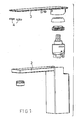
- Figure 1 schematically shows a perspective exploded view of a first embodiment of a faucet-mixer device 1 according to the present invention, comprising an elongated water delivery assembly 2 and a body, integral or rigid with said water delivery assembly 2, inside of which is arranged a mixer device driven by an elongated, preferably flat control handle 3, arranged on the top of the water delivery assembly 2.
- the reference number 4 of figure 1 shows two spacer elements made of a soft material, preferably a soft plastic or rubber material, which, as clearly shown in the enlarged detail of figure 2c , are applied on that surface of the control handle 3 facing the water delivery assembly 2 for preventing said handle 3 from contacting the water delivery assembly 2.
- the two spacer elements 4 have different colors and conventionally indicate the direction the control handle 3 must be turned toward to deliver hot water, respectively cold water.
- Figures 1 to 4 show two parallelepiped shape spacer elements 4 but, without :departing from the scope of the invention, it would be possible to apply on that surface of the.control handle 3 facing the water delivery assembly 2 either one or more spacer elements 4 of any desired shapes.
- Figure 2 schematically shows a front view ( figure 2a ) of the faucet-mixer device 1 of figure 1 , a cross sectional view ( figure 2b ) thereof, substantially taken along the section plane A-A of figure 2a and further shows, on an enlarged scale, the detail shown in figure 2a (figure 2c ).
- the water delivery 2 and control handle 3 have a flat configuration and substantially the same length, that the top surface of the water delivery 2 and bottom surface of the handle 3 are parallel to one another as the spacer elements 4 bear on the top surface of the water delivery 2 and that said spacer elements 4, also shown in figure 2a and better shown in the enlarged detail of figure 2c , are clamped to the free end portion of the control handle 3, that is to that end portion of the handle 3 which is not coupled to the mixer device or assembly.
- Figure 2c schematically shows, on an enlarged scale, the detail shown in figure 2a whereas in figure 2c are clearly shown the spacer elements 4 arranged between the water delivery assembly 2 and control handle 3 and clamped to the free end portion of the handle 3.
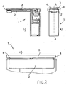
- Figure 3 schematically shows a perspective exploded view of a second embodiment of a faucet-mixer device 1 according to the present invention, differing from the above disclosed first embodiment thereof essentially by the fact that the top surface of the water delivery 2 and bottom surface of the handle 3 are curved and that said handle 3 has a length smaller than that of the delivery assembly 2, as is better shown in figure 4b .
- a recess 5 is provided on the top surface of the water delivery 2 , better shown in figure 4c , allowing a user to easily access the free end portion of the control handle 3.
- Figure 4 schematically shows a front view ( figure 4a ) of the faucet-mixer device 1 of figure 3 , as cross-sectioned according to the section plane B-B of figure 4b , a cross sectional view ( figure 4b ) thereof substantially taken along the section plane A-A of figure 4a and further shows, on an enlarged scale, the detail shown in figure 4a (figure 4c ).
- Figure 4c schematically shows, on an enlarged scale, the detail shown in figure 4a ; in figure 4c , in particular, are clearly shown the spacer elements 4, arranged between the water delivery assembly 2 and control handle 3 and clamped or fixed to the free end portion of the control handle 3.
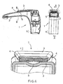
- Figure 5 schematically shows a perspective exploded view of a third embodiment of a faucet-mixer device 1 according to the present invention, differing from the second above disclosed embodiment essential by the fact that at least a spacer element comprises a cap element 6 threaded on the free end portion of the handle 3, as better shown in figure 6b .
- Figure 6 schematically shows a front view ( figure 6a ) of the faucet-mixer device 1 of figure 5 , as cross-sectioned according to the section plane B-B of figure 6b , a cross sectional view ( figure 6b ) thereof substantially taken along the plane A-A of figure 6a and further shows, on an enlarged scale, the detail shown in figure 6a (figure 6c ).
- cap element 6 shown in cross section in figure 6a and in the enlarge detail of figure 6c , is threaded on the free end portion of the control handle 3 and bears on the outer surface of the hot water delivery 2 at said recess 5.
- Figure 6c schematically shows, on an enlarged scale, the detail shown in figure 6a; figure 6c clearly shows the cap element 6 arranged between the water delivery assembly 2 and control handle 3 and threaded on the free end portion of the handle 3.
- cap element 6 may be threaded on the free end portion of the handle 3 of the faucet-mixer device 1 shown in figures 1 and 2 .
- FIG 7 schematically shows a perspective exploded view of a fourth embodiment of a faucet-mixer device 1 according to the present invention, differing from the above disclosed third embodiment thereof essentially by the fact that to the cap element 6 threaded on the free end portion of the control handle 3, is applied.at least a spacer element 41, preferably analogous to the spacer elements 4 shown in figures 1 to 4 .
- FIG 7 are shown two parallelepiped-shape spacer elements 41 to be applied to the cap element 6 but, without departing from the scope of the invention, it would be possible to apply to said cap element 6 either one or more spacer elements 41 of any desired shape, having, preferably, different colors for conventionally indicating the direction the control handle 3 must be turned toward to cause hot water respectively cold water to be delivered from the faucet.
- Figure 8 schematically shows a front view ( figure 8a ) of the faucet-mixer device 1 of figure 7 , as cross-sectioned according to the section plane B-B of figure 8b , a cross sectional view ( figure 8b ) thereof substantially taken along the section plane A-A of figure 8a and further shows, on an enlarged scale, the detail shown in figure 8a (figure 8c ).
- cap element 6 is threaded onto free end portion of the control handle 3 and bears the spacer elements 41 in turn bearing on the outer surface of the water delivery 2 at said recess 5, also shown in figure 8a and better shown in the enlarged detail of figure 8c .
- Figure 8c schematically shows, on an enlarged scale, the detail shown in figure 8a ; in figure 8c it is clearly possible to see the cap element 6 threaded on the free end portion of the control handle 3 as well as the spacer elements 41, arranged between the water delivery assembly 2 and cap element 6 threaded on the end portion of the control handle 3.
- cap elements 6 bearing the spacer elements 41 may also be threaded on the free end portion of the handle 3 of the faucet-mixer device 1 shown in figures 1 and 2 .
Landscapes
- Engineering & Computer Science (AREA)
- General Engineering & Computer Science (AREA)
- Mechanical Engineering (AREA)
- Health & Medical Sciences (AREA)
- Life Sciences & Earth Sciences (AREA)
- Hydrology & Water Resources (AREA)
- Public Health (AREA)
- Water Supply & Treatment (AREA)
- Domestic Plumbing Installations (AREA)
- Multiple-Way Valves (AREA)
- Accessories For Mixers (AREA)
Claims (11)
- Wasserhahn-Mischvorrichtung (1), umfassend eine gestreckte Wasseraustrittsbaugruppe(2) und einen Körper, der einstückig oder starr mit der Wasseraustrittsbaugruppe (2) angeordnet ist und in dem eine Mischvorrichtung angeordnet ist, die durch einen gestreckten, vorzugsweise flachen Regelgriff (3) geregelt ist, welcher auf der Wasseraustrittsbaugruppe (2) angeordnet ist, dadurch gekennzeichnet, dass auf einer Oberfläche des Regelgriffs (3), die der Wasseraustrittsbaugruppe (2) der Wasserhahn-Mischvorrichtung (1) zugekehrt ist, zumindest ein Abstandselement (4, 6, 41) angebracht ist, dass zum Verhindern gestaltet ist, dass der Regelgriff (3) die Wasseraustrittsbaugruppe (2) berührt, wobei das Abstandselement (4, 6) an einem freien Endabschnitt des Regelgriffs (3) angebracht ist.
- Wasserhahn-Mischvorrichtung (1) nach Anspruch 1, dadurch gekennzeichnet, dass das Abstandselement (4, 6, 41) aus einem weichen Material hergestellt ist.
- Wasserhahn-Mischvorrichtung (1) nach Anspruch 2, dadurch gekennzeichnet, dass das Abstandselement (4, 6, 41) aus einem Kunststoffmaterial hergestellt ist.
- Wasserhahn-Mischvorrichtung (1) nach Anspruch 2, dadurch gekennzeichnet, dass das Abstandselement (4, 6, 41) aus einem Kautschukmaterial hergestellt ist.
- Wasserhahn-Mischvorrichtung (1) nach Anspruch 4, dadurch gekennzeichnet, dass eine obere Oberfläche der Wasseraustrittsbaugruppe (2) und eine untere Oberfläche des Regelgriffs (3) parallel zueinander sind, wenn das Abstandselement (4, 6, 41) auf der oberen Oberfläche der Wasseraustrittsbaugruppe (2) aufliegt.
- Wasserhahn-Mischvorrichtung (1) nach Anspruch 1, dadurch gekennzeichnet, dass auf einer Oberfläche des Regelgriffs (3), die der Wasseraustrittsbaugruppe (2) zugekehrt ist, zwei Abstandselemente (4, 41) angebracht sind.
- Wasserhahn-Mischvorrichtung (1) nach Anspruch 6, dadurch gekennzeichnet, dass die zwei Abstandselemente (4, 41) unterschiedliche Farben aufweisen.
- Wasserhahn-Mischvorrichtung (1) nach Anspruch 7, dadurch gekennzeichnet, dass die zwei verschiedenfarbigen Abstandselemente (4, 41) derart gestaltet sind, dass sie auf herkömmliche Weise eine Richtung anzeigen, in der der Regelgriff (3) gedreht werden muss, um zu bewirken, dass die Wasserhahn-Mischvorrichtung (1) heißes Wasser bzw. kaltes Wasser abgibt.
- Wasserhahn-Mischvorrichtung (1) nach Anspruch 1, dadurch gekennzeichnet, dass das zumindest eine Abstandselement ein Deckelelement (6) umfasst, das über Gewinde auf dem freien Endabschnitt des Regelgriffs (3) angebracht ist.
- Wasserhahn-Mischvorrichtung (1) nach Anspruch 1, dadurch gekennzeichnet, dass das zumindest eine Abstandselement ein Deckelelement (6), das über Gewinde auf dem freien Endabschnitt des Regelgriffs (3) angebracht ist, und zumindest ein Abstandselement (41) umfasst, das zwischen dem Deckelelement (6) und der oberen Oberfläche der Wasseraustrittsbaugruppe (2) angeordnet ist.
- Wasserhahn-Mischvorrichtung (1) nach Anspruch 1, wobei die obere Oberfläche der Wasseraustrittsbaugruppe (2) eine gekrümmte Konfiguration aufweist, der Regelgriff (3) eine Länge aufweist, die kürzer als eine Länge der Wasseraustrittsbaugruppe (2) ist, und wobei auf der oberen Oberfläche der Wasseraustrittsbaugruppe eine Aussparung (5) ausgebildet ist, dadurch gekennzeichnet, dass zumindest ein Abstandselement (4, 6, 41) auf einer Außenfläche der Wasseraustrittsbaugruppe (2) an der Aussparung (5) aufliegt.
Applications Claiming Priority (1)
| Application Number | Priority Date | Filing Date | Title |
|---|---|---|---|
| IT000154U ITMI20080154U1 (it) | 2008-04-28 | 2008-04-28 | Rubinetto-miscelatore comprendente almeno un distanziatore posto tra la maniglia e l'erogatore |
Publications (3)
| Publication Number | Publication Date |
|---|---|
| EP2113697A2 EP2113697A2 (de) | 2009-11-04 |
| EP2113697A3 EP2113697A3 (de) | 2010-06-30 |
| EP2113697B1 true EP2113697B1 (de) | 2011-07-20 |
Family
ID=40297534
Family Applications (1)
| Application Number | Title | Priority Date | Filing Date |
|---|---|---|---|
| EP09005825A Not-in-force EP2113697B1 (de) | 2008-04-28 | 2009-04-27 | Wasserhahn-Mischvorrichtung mit mindestens einem zwischen dem Griff und der Wasseraustrittsbaugruppe angeordneten Abstandselement |
Country Status (4)
| Country | Link |
|---|---|
| EP (1) | EP2113697B1 (de) |
| AT (1) | ATE517286T1 (de) |
| ES (1) | ES2369871T3 (de) |
| IT (1) | ITMI20080154U1 (de) |
Families Citing this family (2)
| Publication number | Priority date | Publication date | Assignee | Title |
|---|---|---|---|---|
| GB201122232D0 (en) * | 2011-12-23 | 2012-02-01 | Kohler Mira Ltd | A faucet and a method of connecting a control lever in a faucet to a valve |
| US11021856B2 (en) * | 2013-10-28 | 2021-06-01 | Phoenix Industries Pty Ltd. | Water mixer with lever handle |
Family Cites Families (4)
| Publication number | Priority date | Publication date | Assignee | Title |
|---|---|---|---|---|
| DE3938531A1 (de) * | 1989-11-21 | 1991-05-23 | Ideal Standard | Einhebelmischarmatur |
| US5660208A (en) * | 1992-07-07 | 1997-08-26 | Caspro, S.A. | Monoblock faucet |
| DE19923899C2 (de) * | 1999-05-25 | 2003-11-27 | Hans-Georg Boehm | Zweistufen Einhandmisch-Wasserhahn |
| DE19930218B4 (de) * | 1999-06-30 | 2004-10-07 | Grohe Water Technology Ag & Co. Kg | Betätigungseinrichtung |
-
2008
- 2008-04-28 IT IT000154U patent/ITMI20080154U1/it unknown
-
2009
- 2009-04-27 EP EP09005825A patent/EP2113697B1/de not_active Not-in-force
- 2009-04-27 ES ES09005825T patent/ES2369871T3/es active Active
- 2009-04-27 AT AT09005825T patent/ATE517286T1/de not_active IP Right Cessation
Also Published As
| Publication number | Publication date |
|---|---|
| ATE517286T1 (de) | 2011-08-15 |
| EP2113697A3 (de) | 2010-06-30 |
| EP2113697A2 (de) | 2009-11-04 |
| ES2369871T3 (es) | 2011-12-07 |
| ITMI20080154U1 (it) | 2009-10-28 |
Similar Documents
| Publication | Publication Date | Title |
|---|---|---|
| USD613113S1 (en) | Top panel of a water dispensing machine | |
| USD580525S1 (en) | Faucet assembly | |
| USD581020S1 (en) | Faucet handle | |
| AU2002365326A1 (en) | Media recommender which presents the user with rationale for the recommendation | |
| AU2002213211A1 (en) | Hand-held shower system with inline adjustable temperature/pressure balanced mixing valve | |
| USD581716S1 (en) | Bulk liquid dispenser | |
| USD551760S1 (en) | Dispensing container-single channel | |
| WO2009037608A3 (en) | Applicator with helical applicator surface | |
| AU2001247429A1 (en) | Footwear bladder with controlled flex tensile member | |
| ZA200805038B (en) | Antibodies against amyloid beta 4 with glycosylated in the variable region | |
| GB0606194D0 (en) | Flow control element for use with leak-proof cup assemblies | |
| USD573693S1 (en) | Hot and cold water mixing faucet | |
| EP2113697B1 (de) | Wasserhahn-Mischvorrichtung mit mindestens einem zwischen dem Griff und der Wasseraustrittsbaugruppe angeordneten Abstandselement | |
| IL171936A0 (en) | Fluid control device with heater | |
| EP1639925A3 (de) | Milchschäumvorrichtung mit Bläschenformer | |
| PL371112A1 (en) | Cooking utensil with temperature indicating means | |
| WO2007116274A3 (en) | Multiple configuration shower device | |
| USD604345S1 (en) | Adjustable guide | |
| USD512133S1 (en) | Tub spout | |
| USD599120S1 (en) | Backlit mirror with TV | |
| USD575999S1 (en) | Unitary portion control dispenser and spreader | |
| USD567065S1 (en) | Bar lock assembly guide plate | |
| USD560517S1 (en) | Oval thermostat with roller | |
| EP2439345A1 (de) | Schaltvorrichtung für Sanitäreinbauten, insbesondere Duschen, Badewannen und dergleichen | |
| AU2002359112A1 (en) | Generic array dispenser with laminar virtual flow channels |
Legal Events
| Date | Code | Title | Description |
|---|---|---|---|
| PUAI | Public reference made under article 153(3) epc to a published international application that has entered the european phase |
Free format text: ORIGINAL CODE: 0009012 |
|
| AK | Designated contracting states |
Kind code of ref document: A2 Designated state(s): AT BE BG CH CY CZ DE DK EE ES FI FR GB GR HR HU IE IS IT LI LT LU LV MC MK MT NL NO PL PT RO SE SI SK TR |
|
| PUAL | Search report despatched |
Free format text: ORIGINAL CODE: 0009013 |
|
| AK | Designated contracting states |
Kind code of ref document: A3 Designated state(s): AT BE BG CH CY CZ DE DK EE ES FI FR GB GR HR HU IE IS IT LI LT LU LV MC MK MT NL NO PL PT RO SE SI SK TR |
|
| AX | Request for extension of the european patent |
Extension state: AL BA RS |
|
| 17P | Request for examination filed |
Effective date: 20101206 |
|
| GRAP | Despatch of communication of intention to grant a patent |
Free format text: ORIGINAL CODE: EPIDOSNIGR1 |
|
| RIC1 | Information provided on ipc code assigned before grant |
Ipc: F16K 31/60 20060101AFI20110113BHEP |
|
| GRAS | Grant fee paid |
Free format text: ORIGINAL CODE: EPIDOSNIGR3 |
|
| GRAA | (expected) grant |
Free format text: ORIGINAL CODE: 0009210 |
|
| AK | Designated contracting states |
Kind code of ref document: B1 Designated state(s): AT BE BG CH CY CZ DE DK EE ES FI FR GB GR HR HU IE IS IT LI LT LU LV MC MK MT NL NO PL PT RO SE SI SK TR |
|
| REG | Reference to a national code |
Ref country code: GB Ref legal event code: FG4D |
|
| REG | Reference to a national code |
Ref country code: CH Ref legal event code: EP |
|
| REG | Reference to a national code |
Ref country code: DE Ref legal event code: R096 Ref document number: 602009001826 Country of ref document: DE Effective date: 20110922 |
|
| REG | Reference to a national code |
Ref country code: NL Ref legal event code: VDEP Effective date: 20110720 |
|
| REG | Reference to a national code |
Ref country code: ES Ref legal event code: FG2A Ref document number: 2369871 Country of ref document: ES Kind code of ref document: T3 Effective date: 20111207 |
|
| REG | Reference to a national code |
Ref country code: AT Ref legal event code: MK05 Ref document number: 517286 Country of ref document: AT Kind code of ref document: T Effective date: 20110720 |
|
| PG25 | Lapsed in a contracting state [announced via postgrant information from national office to epo] |
Ref country code: FI Free format text: LAPSE BECAUSE OF FAILURE TO SUBMIT A TRANSLATION OF THE DESCRIPTION OR TO PAY THE FEE WITHIN THE PRESCRIBED TIME-LIMIT Effective date: 20110720 Ref country code: HR Free format text: LAPSE BECAUSE OF FAILURE TO SUBMIT A TRANSLATION OF THE DESCRIPTION OR TO PAY THE FEE WITHIN THE PRESCRIBED TIME-LIMIT Effective date: 20110720 Ref country code: LT Free format text: LAPSE BECAUSE OF FAILURE TO SUBMIT A TRANSLATION OF THE DESCRIPTION OR TO PAY THE FEE WITHIN THE PRESCRIBED TIME-LIMIT Effective date: 20110720 Ref country code: NL Free format text: LAPSE BECAUSE OF FAILURE TO SUBMIT A TRANSLATION OF THE DESCRIPTION OR TO PAY THE FEE WITHIN THE PRESCRIBED TIME-LIMIT Effective date: 20110720 Ref country code: NO Free format text: LAPSE BECAUSE OF FAILURE TO SUBMIT A TRANSLATION OF THE DESCRIPTION OR TO PAY THE FEE WITHIN THE PRESCRIBED TIME-LIMIT Effective date: 20111020 Ref country code: IS Free format text: LAPSE BECAUSE OF FAILURE TO SUBMIT A TRANSLATION OF THE DESCRIPTION OR TO PAY THE FEE WITHIN THE PRESCRIBED TIME-LIMIT Effective date: 20111120 Ref country code: BE Free format text: LAPSE BECAUSE OF FAILURE TO SUBMIT A TRANSLATION OF THE DESCRIPTION OR TO PAY THE FEE WITHIN THE PRESCRIBED TIME-LIMIT Effective date: 20110720 Ref country code: PT Free format text: LAPSE BECAUSE OF FAILURE TO SUBMIT A TRANSLATION OF THE DESCRIPTION OR TO PAY THE FEE WITHIN THE PRESCRIBED TIME-LIMIT Effective date: 20111121 Ref country code: SE Free format text: LAPSE BECAUSE OF FAILURE TO SUBMIT A TRANSLATION OF THE DESCRIPTION OR TO PAY THE FEE WITHIN THE PRESCRIBED TIME-LIMIT Effective date: 20110720 |
|
| PG25 | Lapsed in a contracting state [announced via postgrant information from national office to epo] |
Ref country code: LV Free format text: LAPSE BECAUSE OF FAILURE TO SUBMIT A TRANSLATION OF THE DESCRIPTION OR TO PAY THE FEE WITHIN THE PRESCRIBED TIME-LIMIT Effective date: 20110720 Ref country code: AT Free format text: LAPSE BECAUSE OF FAILURE TO SUBMIT A TRANSLATION OF THE DESCRIPTION OR TO PAY THE FEE WITHIN THE PRESCRIBED TIME-LIMIT Effective date: 20110720 Ref country code: SI Free format text: LAPSE BECAUSE OF FAILURE TO SUBMIT A TRANSLATION OF THE DESCRIPTION OR TO PAY THE FEE WITHIN THE PRESCRIBED TIME-LIMIT Effective date: 20110720 Ref country code: PL Free format text: LAPSE BECAUSE OF FAILURE TO SUBMIT A TRANSLATION OF THE DESCRIPTION OR TO PAY THE FEE WITHIN THE PRESCRIBED TIME-LIMIT Effective date: 20110720 Ref country code: CY Free format text: LAPSE BECAUSE OF FAILURE TO SUBMIT A TRANSLATION OF THE DESCRIPTION OR TO PAY THE FEE WITHIN THE PRESCRIBED TIME-LIMIT Effective date: 20110720 Ref country code: GR Free format text: LAPSE BECAUSE OF FAILURE TO SUBMIT A TRANSLATION OF THE DESCRIPTION OR TO PAY THE FEE WITHIN THE PRESCRIBED TIME-LIMIT Effective date: 20111021 |
|
| PG25 | Lapsed in a contracting state [announced via postgrant information from national office to epo] |
Ref country code: CZ Free format text: LAPSE BECAUSE OF FAILURE TO SUBMIT A TRANSLATION OF THE DESCRIPTION OR TO PAY THE FEE WITHIN THE PRESCRIBED TIME-LIMIT Effective date: 20110720 Ref country code: SK Free format text: LAPSE BECAUSE OF FAILURE TO SUBMIT A TRANSLATION OF THE DESCRIPTION OR TO PAY THE FEE WITHIN THE PRESCRIBED TIME-LIMIT Effective date: 20110720 |
|
| PLBE | No opposition filed within time limit |
Free format text: ORIGINAL CODE: 0009261 |
|
| STAA | Information on the status of an ep patent application or granted ep patent |
Free format text: STATUS: NO OPPOSITION FILED WITHIN TIME LIMIT |
|
| PG25 | Lapsed in a contracting state [announced via postgrant information from national office to epo] |
Ref country code: EE Free format text: LAPSE BECAUSE OF FAILURE TO SUBMIT A TRANSLATION OF THE DESCRIPTION OR TO PAY THE FEE WITHIN THE PRESCRIBED TIME-LIMIT Effective date: 20110720 Ref country code: RO Free format text: LAPSE BECAUSE OF FAILURE TO SUBMIT A TRANSLATION OF THE DESCRIPTION OR TO PAY THE FEE WITHIN THE PRESCRIBED TIME-LIMIT Effective date: 20110720 |
|
| 26N | No opposition filed |
Effective date: 20120423 |
|
| PG25 | Lapsed in a contracting state [announced via postgrant information from national office to epo] |
Ref country code: DK Free format text: LAPSE BECAUSE OF FAILURE TO SUBMIT A TRANSLATION OF THE DESCRIPTION OR TO PAY THE FEE WITHIN THE PRESCRIBED TIME-LIMIT Effective date: 20110720 |
|
| REG | Reference to a national code |
Ref country code: DE Ref legal event code: R097 Ref document number: 602009001826 Country of ref document: DE Effective date: 20120423 |
|
| PG25 | Lapsed in a contracting state [announced via postgrant information from national office to epo] |
Ref country code: MC Free format text: LAPSE BECAUSE OF NON-PAYMENT OF DUE FEES Effective date: 20120430 |
|
| REG | Reference to a national code |
Ref country code: FR Ref legal event code: ST Effective date: 20121228 |
|
| PG25 | Lapsed in a contracting state [announced via postgrant information from national office to epo] |
Ref country code: FR Free format text: LAPSE BECAUSE OF NON-PAYMENT OF DUE FEES Effective date: 20120430 Ref country code: MK Free format text: LAPSE BECAUSE OF FAILURE TO SUBMIT A TRANSLATION OF THE DESCRIPTION OR TO PAY THE FEE WITHIN THE PRESCRIBED TIME-LIMIT Effective date: 20110720 |
|
| PG25 | Lapsed in a contracting state [announced via postgrant information from national office to epo] |
Ref country code: IE Free format text: LAPSE BECAUSE OF NON-PAYMENT OF DUE FEES Effective date: 20120427 |
|
| PG25 | Lapsed in a contracting state [announced via postgrant information from national office to epo] |
Ref country code: BG Free format text: LAPSE BECAUSE OF FAILURE TO SUBMIT A TRANSLATION OF THE DESCRIPTION OR TO PAY THE FEE WITHIN THE PRESCRIBED TIME-LIMIT Effective date: 20111020 |
|
| PG25 | Lapsed in a contracting state [announced via postgrant information from national office to epo] |
Ref country code: MT Free format text: LAPSE BECAUSE OF FAILURE TO SUBMIT A TRANSLATION OF THE DESCRIPTION OR TO PAY THE FEE WITHIN THE PRESCRIBED TIME-LIMIT Effective date: 20110720 |
|
| PGFP | Annual fee paid to national office [announced via postgrant information from national office to epo] |
Ref country code: DE Payment date: 20130904 Year of fee payment: 5 Ref country code: ES Payment date: 20130903 Year of fee payment: 5 |
|
| REG | Reference to a national code |
Ref country code: CH Ref legal event code: PL |
|
| GBPC | Gb: european patent ceased through non-payment of renewal fee |
Effective date: 20130427 |
|
| PG25 | Lapsed in a contracting state [announced via postgrant information from national office to epo] |
Ref country code: LI Free format text: LAPSE BECAUSE OF NON-PAYMENT OF DUE FEES Effective date: 20130430 Ref country code: GB Free format text: LAPSE BECAUSE OF NON-PAYMENT OF DUE FEES Effective date: 20130427 Ref country code: CH Free format text: LAPSE BECAUSE OF NON-PAYMENT OF DUE FEES Effective date: 20130430 |
|
| PG25 | Lapsed in a contracting state [announced via postgrant information from national office to epo] |
Ref country code: TR Free format text: LAPSE BECAUSE OF FAILURE TO SUBMIT A TRANSLATION OF THE DESCRIPTION OR TO PAY THE FEE WITHIN THE PRESCRIBED TIME-LIMIT Effective date: 20110720 |
|
| PG25 | Lapsed in a contracting state [announced via postgrant information from national office to epo] |
Ref country code: LU Free format text: LAPSE BECAUSE OF NON-PAYMENT OF DUE FEES Effective date: 20120427 |
|
| PG25 | Lapsed in a contracting state [announced via postgrant information from national office to epo] |
Ref country code: HU Free format text: LAPSE BECAUSE OF FAILURE TO SUBMIT A TRANSLATION OF THE DESCRIPTION OR TO PAY THE FEE WITHIN THE PRESCRIBED TIME-LIMIT Effective date: 20090427 |
|
| REG | Reference to a national code |
Ref country code: DE Ref legal event code: R119 Ref document number: 602009001826 Country of ref document: DE |
|
| REG | Reference to a national code |
Ref country code: DE Ref legal event code: R119 Ref document number: 602009001826 Country of ref document: DE Effective date: 20141101 |
|
| PG25 | Lapsed in a contracting state [announced via postgrant information from national office to epo] |
Ref country code: DE Free format text: LAPSE BECAUSE OF NON-PAYMENT OF DUE FEES Effective date: 20141101 |
|
| PGFP | Annual fee paid to national office [announced via postgrant information from national office to epo] |
Ref country code: IT Payment date: 20150326 Year of fee payment: 7 |
|
| REG | Reference to a national code |
Ref country code: ES Ref legal event code: FD2A Effective date: 20151229 |
|
| PG25 | Lapsed in a contracting state [announced via postgrant information from national office to epo] |
Ref country code: ES Free format text: LAPSE BECAUSE OF NON-PAYMENT OF DUE FEES Effective date: 20140428 |
|
| PG25 | Lapsed in a contracting state [announced via postgrant information from national office to epo] |
Ref country code: IT Free format text: LAPSE BECAUSE OF NON-PAYMENT OF DUE FEES Effective date: 20160427 |