EP2113634A2 - Gas turbine engine case with replaced flange and method of repairing the same using cold metal transfer - Google Patents
Gas turbine engine case with replaced flange and method of repairing the same using cold metal transfer Download PDFInfo
- Publication number
- EP2113634A2 EP2113634A2 EP09250976A EP09250976A EP2113634A2 EP 2113634 A2 EP2113634 A2 EP 2113634A2 EP 09250976 A EP09250976 A EP 09250976A EP 09250976 A EP09250976 A EP 09250976A EP 2113634 A2 EP2113634 A2 EP 2113634A2
- Authority
- EP
- European Patent Office
- Prior art keywords
- engine case
- flange
- engine
- replacement
- metal transfer
- Prior art date
- Legal status (The legal status is an assumption and is not a legal conclusion. Google has not performed a legal analysis and makes no representation as to the accuracy of the status listed.)
- Granted
Links
- 238000000034 method Methods 0.000 title claims abstract description 24
- 239000002184 metal Substances 0.000 title claims abstract description 13
- 238000003466 welding Methods 0.000 claims description 12
- 239000007789 gas Substances 0.000 description 11
- 230000008439 repair process Effects 0.000 description 11
- 239000000306 component Substances 0.000 description 7
- 238000002360 preparation method Methods 0.000 description 4
- 238000002485 combustion reaction Methods 0.000 description 3
- 238000005520 cutting process Methods 0.000 description 3
- 239000000463 material Substances 0.000 description 3
- 239000008358 core component Substances 0.000 description 1
- 238000010894 electron beam technology Methods 0.000 description 1
- 239000000446 fuel Substances 0.000 description 1
- 239000011261 inert gas Substances 0.000 description 1
- 238000012423 maintenance Methods 0.000 description 1
- 238000012986 modification Methods 0.000 description 1
- 230000004048 modification Effects 0.000 description 1
- 238000004886 process control Methods 0.000 description 1
- 230000003068 static effect Effects 0.000 description 1
Images



Classifications
-
- F—MECHANICAL ENGINEERING; LIGHTING; HEATING; WEAPONS; BLASTING
- F01—MACHINES OR ENGINES IN GENERAL; ENGINE PLANTS IN GENERAL; STEAM ENGINES
- F01D—NON-POSITIVE DISPLACEMENT MACHINES OR ENGINES, e.g. STEAM TURBINES
- F01D5/00—Blades; Blade-carrying members; Heating, heat-insulating, cooling or antivibration means on the blades or the members
- F01D5/005—Repairing methods or devices
-
- B—PERFORMING OPERATIONS; TRANSPORTING
- B23—MACHINE TOOLS; METAL-WORKING NOT OTHERWISE PROVIDED FOR
- B23P—METAL-WORKING NOT OTHERWISE PROVIDED FOR; COMBINED OPERATIONS; UNIVERSAL MACHINE TOOLS
- B23P6/00—Restoring or reconditioning objects
- B23P6/002—Repairing turbine components, e.g. moving or stationary blades, rotors
- B23P6/005—Repairing turbine components, e.g. moving or stationary blades, rotors using only replacement pieces of a particular form
-
- F—MECHANICAL ENGINEERING; LIGHTING; HEATING; WEAPONS; BLASTING
- F01—MACHINES OR ENGINES IN GENERAL; ENGINE PLANTS IN GENERAL; STEAM ENGINES
- F01D—NON-POSITIVE DISPLACEMENT MACHINES OR ENGINES, e.g. STEAM TURBINES
- F01D25/00—Component parts, details, or accessories, not provided for in, or of interest apart from, other groups
- F01D25/24—Casings; Casing parts, e.g. diaphragms, casing fastenings
-
- B—PERFORMING OPERATIONS; TRANSPORTING
- B23—MACHINE TOOLS; METAL-WORKING NOT OTHERWISE PROVIDED FOR
- B23K—SOLDERING OR UNSOLDERING; WELDING; CLADDING OR PLATING BY SOLDERING OR WELDING; CUTTING BY APPLYING HEAT LOCALLY, e.g. FLAME CUTTING; WORKING BY LASER BEAM
- B23K2101/00—Articles made by soldering, welding or cutting
- B23K2101/001—Turbines
-
- F—MECHANICAL ENGINEERING; LIGHTING; HEATING; WEAPONS; BLASTING
- F05—INDEXING SCHEMES RELATING TO ENGINES OR PUMPS IN VARIOUS SUBCLASSES OF CLASSES F01-F04
- F05D—INDEXING SCHEME FOR ASPECTS RELATING TO NON-POSITIVE-DISPLACEMENT MACHINES OR ENGINES, GAS-TURBINES OR JET-PROPULSION PLANTS
- F05D2230/00—Manufacture
- F05D2230/20—Manufacture essentially without removing material
- F05D2230/23—Manufacture essentially without removing material by permanently joining parts together
- F05D2230/232—Manufacture essentially without removing material by permanently joining parts together by welding
-
- F—MECHANICAL ENGINEERING; LIGHTING; HEATING; WEAPONS; BLASTING
- F05—INDEXING SCHEMES RELATING TO ENGINES OR PUMPS IN VARIOUS SUBCLASSES OF CLASSES F01-F04
- F05D—INDEXING SCHEME FOR ASPECTS RELATING TO NON-POSITIVE-DISPLACEMENT MACHINES OR ENGINES, GAS-TURBINES OR JET-PROPULSION PLANTS
- F05D2230/00—Manufacture
- F05D2230/20—Manufacture essentially without removing material
- F05D2230/23—Manufacture essentially without removing material by permanently joining parts together
- F05D2230/232—Manufacture essentially without removing material by permanently joining parts together by welding
- F05D2230/235—TIG or MIG welding
-
- F—MECHANICAL ENGINEERING; LIGHTING; HEATING; WEAPONS; BLASTING
- F05—INDEXING SCHEMES RELATING TO ENGINES OR PUMPS IN VARIOUS SUBCLASSES OF CLASSES F01-F04
- F05D—INDEXING SCHEME FOR ASPECTS RELATING TO NON-POSITIVE-DISPLACEMENT MACHINES OR ENGINES, GAS-TURBINES OR JET-PROPULSION PLANTS
- F05D2230/00—Manufacture
- F05D2230/80—Repairing, retrofitting or upgrading methods
-
- Y—GENERAL TAGGING OF NEW TECHNOLOGICAL DEVELOPMENTS; GENERAL TAGGING OF CROSS-SECTIONAL TECHNOLOGIES SPANNING OVER SEVERAL SECTIONS OF THE IPC; TECHNICAL SUBJECTS COVERED BY FORMER USPC CROSS-REFERENCE ART COLLECTIONS [XRACs] AND DIGESTS
- Y10—TECHNICAL SUBJECTS COVERED BY FORMER USPC
- Y10T—TECHNICAL SUBJECTS COVERED BY FORMER US CLASSIFICATION
- Y10T29/00—Metal working
- Y10T29/49—Method of mechanical manufacture
- Y10T29/49316—Impeller making
- Y10T29/49318—Repairing or disassembling
Definitions
- This application relates to a repaired gas turbine engine case and method of repair, wherein cold metal transfer is utilized for a replacement weld joint to attach a replacement flange.
- Gas turbine engines are known, and include engine cases surrounding several core components. Engine cases typically abut other housing members at flanges, which may then be utilized to connect the engine case to the adjacent housing. The engine cases are subject to a harsh environment during service, and may be damaged. As an example, products of combustion at high temperature pass within the engine case.
- a gas turbine engine Periodically, a gas turbine engine is taken out of service and reviewed for maintenance issues.
- One engine area that may be subject to repair is the flange of the engine case.
- the engine case has been removed, and the existing flange machined away. A replacement flange may then be attached.
- At least one known prior art process for attaching the flange generally includes use of an electron beam welding device.
- the devices are expensive to purchase and operate.
- the devices are vacuum devices that extend repair time because of additional time to pump down a chamber to an acceptable pressure.
- CMT cold metal transfer
- MIG metal inert gas
- CMT cold has to be understood in terms of a welding process.
- CMT is a cold process. Its characteristic feature is alternating hot and relatively cold temperature. This alternating hot and cold treatment occurs by incorporating a welding wire motion into a process control.
- the wire moves forward and into a weld pool. A short circuit occurs. As the short circuit happens, the wire is pulled back again. In this way, a weld arc only inputs heat very briefly in the arcing period, after which the thermal input is immediately reduced. In this way, the alternating hot and cold occurs.
- the rearward movement of the wire assists weld material droplet detachment during the short circuit.
- the short circuit is thus controlled and kept small.
- a method of repairing an engine case for a gas turbine engine includes identifying a damaged flange on an engine case, removing the damaged flange down to a surface of the case to receive a replacement flange, placing a replacement flange on the surface, and welding the replacement flange to the surface utilizing cold metal transfer.
- a repaired engine case is also claimed.
- a gas turbine engine 10 such as a turbofan gas turbine engine, circumferentially disposed about an engine centerline, or axial centerline axis 12 is shown in Figure 1 .
- the engine 10 includes a fan 14, compressor sections 15 and 16, a combustion section 18 and a turbine 20.
- air compressed in the compressor 15, 16 is mixed with fuel and burned in the combustion section 18 and expanded in turbine 20.
- the turbine 20 includes rotors 22 and 24, which rotate in response to the expansion.
- the turbine 20 includes alternating rows of removable rotary airfoils or blades 26 and static airfoils or vanes 28. It should be understood that this schematic view is included to provide a basic understanding of the sections in a gas turbine engine, and is not to be limiting. This disclosure extends to all types of turbine engines for all types of applications.
- the gas turbine engine 10 also includes an engine case surrounding internal engine components.
- the engine case is attached to adjacent housing parts at flanges at the end of the case. Over time, the engine case can wear at the flanges.
- Figure 2A is a flow chart of a method of repairing a worn engine case 40 such as is shown in Figure 2B .
- the initial step 100 is to removed the case 40 from the engine 10, for example, during a repair or overhaul shop visit.
- the case 40 is cleaned and inspected at step 102 for repair requirements.
- a number of worn or damaged areas 44 may exist on a flange 42 of the engine case 40. These areas 44 may be identified for repair prior to the engine case 40 being reinstalled on the engine 10.
- An initial step 104 in the repair of the engine case 40 is to remove the existing flange 42 down to a substantially flat surface 46 as shown in Figure 3A . This can be achieved by cutting down to dashed line 90 as shown in Figure 2B . Figure 3A shows the surface 46 as a substantially flat surface. A replacement flange 48 may then be utilized.
- Figure 3B shows a preferred preparation for the surface between the two components, engine case 40 and the replacement flange 48.
- chamfers 80 may be formed on both surfaces to create a gap to receive weld material 82.
- This so-called "V" preparation may be used on both the components or just one of the components. Such preparation has been utilized in the past with cold metal transfer techniques, and is particularly desirable for the disclosed embodiment.
- Figure 3C shows yet another preparation for the surface between the two components, engine case 40 and the replacement flange 48.
- an outer chamfer 84 and a radially inner chamfer 86 are formed on each of the components to hold the weld material 88.
- the chamfer may be formed on only one of the two components, or may be formed on both.
- Cutting techniques may be utilized to remove the existing flange 42.
- the engine case can be placed on a turret lathe and the existing flange cut away with a cutting tool.
- other methods of removing the existing flange could be utilized consistent with this application.
- the replacement flange 48 is positioned on the surface 46 at step 106.
- a tack welding device 52 may then apply tack welds 50 to hold the replacement flange 48 on the surface 46 at step 108.
- a final weld joint 54 may be applied along the surface 46 to secure the replacement flange 48 to the engine case 40 at step 110.
- the engine case may now be reinstalled on the engine at step 112.
- the welding equipment 56 may be a cold metal transfer welding equipment. Although cold metal transfer is known, the process has not been utilized for the replacement of a flange on an engine case as disclosed in the exemplary embodiments. As mentioned above, CMT is a process having alternating hot and cold operation as a short circuit repeats with controlled movement of a weld wire 57. As known, the wire may move towards and away from the surface as shown in phantom at 59. Of course, this is a schematic view of the process.
Landscapes
- Engineering & Computer Science (AREA)
- Mechanical Engineering (AREA)
- General Engineering & Computer Science (AREA)
- Structures Of Non-Positive Displacement Pumps (AREA)
- Butt Welding And Welding Of Specific Article (AREA)
Abstract
Description
- This application relates to a repaired gas turbine engine case and method of repair, wherein cold metal transfer is utilized for a replacement weld joint to attach a replacement flange.
- Gas turbine engines are known, and include engine cases surrounding several core components. Engine cases typically abut other housing members at flanges, which may then be utilized to connect the engine case to the adjacent housing. The engine cases are subject to a harsh environment during service, and may be damaged. As an example, products of combustion at high temperature pass within the engine case.
- Periodically, a gas turbine engine is taken out of service and reviewed for maintenance issues. One engine area that may be subject to repair is the flange of the engine case. In the past, the engine case has been removed, and the existing flange machined away. A replacement flange may then be attached.
- At least one known prior art process for attaching the flange generally includes use of an electron beam welding device. However, the devices are expensive to purchase and operate. Also, the devices are vacuum devices that extend repair time because of additional time to pump down a chamber to an acceptable pressure.
- A process known as cold metal transfer ("CMT") developed by the Fronius Corporation has been incorporated into gas metal arc or metal inert gas ("MIG") welding systems. This process reduces the spatter often associated with MIG welding. This spatter has kept MIG welding from gaining popularity in the aerospace industry.
- The term "cold" has to be understood in terms of a welding process. When compared to a conventional MIG/MAG process, CMT is a cold process. Its characteristic feature is alternating hot and relatively cold temperature. This alternating hot and cold treatment occurs by incorporating a welding wire motion into a process control.
- The wire moves forward and into a weld pool. A short circuit occurs. As the short circuit happens, the wire is pulled back again. In this way, a weld arc only inputs heat very briefly in the arcing period, after which the thermal input is immediately reduced. In this way, the alternating hot and cold occurs.
- The rearward movement of the wire assists weld material droplet detachment during the short circuit. The short circuit is thus controlled and kept small.
- CMT has not been utilized in repair applications for gas turbine engine cases.
- A method of repairing an engine case for a gas turbine engine includes identifying a damaged flange on an engine case, removing the damaged flange down to a surface of the case to receive a replacement flange, placing a replacement flange on the surface, and welding the replacement flange to the surface utilizing cold metal transfer. A repaired engine case is also claimed.
- These and other features of the present invention may be best understood from the following specification and drawings, the following of which is a brief description.
-
-
Figure 1 is a schematic view of a gas turbine engine. -
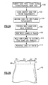
Figure 2A is a flow chart of an exemplary repair method. -
Figure 2B shows a worn engine case. -
Figure 3A shows a first step in a repair process. -
Figure 3B shows an alternative step. -
Figure 3C shows yet another alternative step. -
Figure 3D shows a subsequent step. -
Figure 3E shows a final step in the repair process. - A
gas turbine engine 10, such as a turbofan gas turbine engine, circumferentially disposed about an engine centerline, oraxial centerline axis 12 is shown inFigure 1 . Theengine 10 includes afan 14,compressor sections combustion section 18 and aturbine 20. As is well known in the art, air compressed in thecompressor combustion section 18 and expanded inturbine 20. Theturbine 20 includesrotors turbine 20 includes alternating rows of removable rotary airfoils orblades 26 and static airfoils orvanes 28. It should be understood that this schematic view is included to provide a basic understanding of the sections in a gas turbine engine, and is not to be limiting. This disclosure extends to all types of turbine engines for all types of applications. - The
gas turbine engine 10 also includes an engine case surrounding internal engine components. The engine case is attached to adjacent housing parts at flanges at the end of the case. Over time, the engine case can wear at the flanges. -
Figure 2A is a flow chart of a method of repairing aworn engine case 40 such as is shown inFigure 2B . Theinitial step 100 is to removed thecase 40 from theengine 10, for example, during a repair or overhaul shop visit. Thecase 40 is cleaned and inspected atstep 102 for repair requirements. For example, as shown inFigure 2B , a number of worn or damagedareas 44 may exist on aflange 42 of theengine case 40. Theseareas 44 may be identified for repair prior to theengine case 40 being reinstalled on theengine 10. - An
initial step 104 in the repair of theengine case 40 is to remove the existingflange 42 down to a substantiallyflat surface 46 as shown inFigure 3A . This can be achieved by cutting down to dashedline 90 as shown inFigure 2B .Figure 3A shows thesurface 46 as a substantially flat surface. Areplacement flange 48 may then be utilized. -
Figure 3B shows a preferred preparation for the surface between the two components,engine case 40 and thereplacement flange 48. As shown,chamfers 80 may be formed on both surfaces to create a gap to receiveweld material 82. This so-called "V" preparation may be used on both the components or just one of the components. Such preparation has been utilized in the past with cold metal transfer techniques, and is particularly desirable for the disclosed embodiment. -
Figure 3C shows yet another preparation for the surface between the two components,engine case 40 and thereplacement flange 48. As shown, anouter chamfer 84 and a radiallyinner chamfer 86 are formed on each of the components to hold theweld material 88. Again, the chamfer may be formed on only one of the two components, or may be formed on both. - Cutting techniques may be utilized to remove the existing
flange 42. As one example, the engine case can be placed on a turret lathe and the existing flange cut away with a cutting tool. Of course, other methods of removing the existing flange could be utilized consistent with this application. - As shown in
Figure 3D , thereplacement flange 48 is positioned on thesurface 46 atstep 106. Atack welding device 52 may then apply tack welds 50 to hold thereplacement flange 48 on thesurface 46 atstep 108. - As shown in
Figure 3E , a final weld joint 54 may be applied along thesurface 46 to secure thereplacement flange 48 to theengine case 40 atstep 110. The engine case may now be reinstalled on the engine atstep 112. - The
welding equipment 56 may be a cold metal transfer welding equipment. Although cold metal transfer is known, the process has not been utilized for the replacement of a flange on an engine case as disclosed in the exemplary embodiments. As mentioned above, CMT is a process having alternating hot and cold operation as a short circuit repeats with controlled movement of aweld wire 57. As known, the wire may move towards and away from the surface as shown in phantom at 59. Of course, this is a schematic view of the process. - Although exemplary embodiments have been disclosed, a worker of ordinary skill in this art would recognize that certain modifications would come within the scope of this invention. For that reason, the following claims should be studied to determine the true scope and content of this invention.
Claims (7)
- A method of repairing an engine case (40) for a gas turbine engine, the method comprising the steps of:a) identifying a damaged flange (42) on an engine case (40);b) removing the damaged flange (42) down to a surface (46) of the engine case (40) to receive a replacement flange (48);c) placing the replacement flange (48) on the surface (46); andd) welding the replacement flange (48) to the surface (46) utilizing cold metal transfer.
- The method as set forth in claim 1, wherein tack welds (50) hold the replacement flange (48) on the engine case (40) prior to the step d) welding.
- The method as set forth in claim 1 or 2, wherein step b) includes providing a substantially flat surface (46) machined on the engine case (40) to receive the replacement flange (48).
- The method as set forth in claim 1, 2 or 3, wherein step b) includes providing at least one chamfer (82; 84, 86) at a surface between the engine case (40) and the replacement flange (48).
- The method as set forth in any preceding claim, wherein the cold metal transfer includes moving a wire (57) towards and away from the surface (46) to provide alternating hot and cold operation.
- A repaired engine case (40) comprising:an engine case (40), and a flange (48) at one end of the engine case; anda weld joint (54) holding said flange on said engine case, said weld joint (54) being a cold metal transfer weld joint.
- The repaired engine case as set forth in claim 6, wherein there is at least one chamfer cut (82; 84, 86) at a surface (46) between the engine case (40) and the flange (48) to at least partially receive the weld joint (54).
Applications Claiming Priority (1)
| Application Number | Priority Date | Filing Date | Title |
|---|---|---|---|
| US12/113,980 US8257039B2 (en) | 2008-05-02 | 2008-05-02 | Gas turbine engine case with replaced flange and method of repairing the same using cold metal transfer |
Publications (3)
| Publication Number | Publication Date |
|---|---|
| EP2113634A2 true EP2113634A2 (en) | 2009-11-04 |
| EP2113634A3 EP2113634A3 (en) | 2013-04-03 |
| EP2113634B1 EP2113634B1 (en) | 2016-06-01 |
Family
ID=40887906
Family Applications (1)
| Application Number | Title | Priority Date | Filing Date |
|---|---|---|---|
| EP09250976.9A Revoked EP2113634B1 (en) | 2008-05-02 | 2009-03-31 | Method of repairing a gas turbine engine case with replaced flange using cold metal transfer |
Country Status (2)
| Country | Link |
|---|---|
| US (1) | US8257039B2 (en) |
| EP (1) | EP2113634B1 (en) |
Cited By (7)
| Publication number | Priority date | Publication date | Assignee | Title |
|---|---|---|---|---|
| WO2011064406A1 (en) * | 2009-11-30 | 2011-06-03 | Snecma | Method for making a metal reinforcement for a turbine engine blade |
| CN102179639A (en) * | 2011-04-12 | 2011-09-14 | 兰州理工大学 | Cold metal transition fusion-brazing joining method of dissimilar metals in magnesium steel |
| FR2959434A1 (en) * | 2010-04-30 | 2011-11-04 | Snecma | Aluminum retention casing repairing method for aircraft turbomachine, involves reconstructing flange by reloading metal on flange lower part surface by metal inert gas welding apparatus, and machining metal to obtain flange's final geometry |
| WO2015022459A1 (en) * | 2013-08-14 | 2015-02-19 | Aircelle | Assembly comprising a collet provided with a flange comprising an annular hollow receiving folds of composite materials |
| EP2564979A3 (en) * | 2011-08-29 | 2017-01-25 | United Technologies Corporation | Bushing to repair circumferential flanged ring |
| CN113664456A (en) * | 2021-08-10 | 2021-11-19 | 西安远航真空钎焊技术有限公司 | Combustion chamber barrel repairing method based on compensation structure |
| CN115351502A (en) * | 2022-08-11 | 2022-11-18 | 湖北航达科技有限公司 | Deep repair method for air conditioning system |
Families Citing this family (5)
| Publication number | Priority date | Publication date | Assignee | Title |
|---|---|---|---|---|
| EP2410138B8 (en) * | 2010-07-22 | 2017-07-19 | Ansaldo Energia IP UK Limited | Gas turbine engine flange arrangement and method for retrofitting same |
| CN103801799B (en) * | 2012-11-12 | 2017-11-21 | 通用电气公司 | The revolving meber for manufacturing the method for revolving meber and being manufactured with this method |
| US9856753B2 (en) | 2015-06-10 | 2018-01-02 | United Technologies Corporation | Inner diameter scallop case flange for a case of a gas turbine engine |
| CN111727099A (en) * | 2017-11-28 | 2020-09-29 | 坎杜能源公司 | Method and apparatus for repairing tubular structures |
| US11268408B2 (en) * | 2019-10-31 | 2022-03-08 | Chromalloy Gas Turbine Llc | Method of repairing an engine case flange |
Citations (2)
| Publication number | Priority date | Publication date | Assignee | Title |
|---|---|---|---|---|
| EP1602442A1 (en) | 2004-06-01 | 2005-12-07 | United Technologies Corporation | Methods for repairing gas turbine engine components |
| WO2007109416A2 (en) | 2006-03-22 | 2007-09-27 | Gm Global Technology Operations, Inc. | Method for joining or repairing metal surface parts |
Family Cites Families (34)
| Publication number | Priority date | Publication date | Assignee | Title |
|---|---|---|---|---|
| US2940779A (en) * | 1957-11-08 | 1960-06-14 | Taylor Forge & Pipe Works | Balanced face flange |
| US4408112A (en) | 1981-06-12 | 1983-10-04 | Gasparas Kazlauskas | Welding insert ring and method of welding therefor |
| US4549058A (en) | 1983-09-30 | 1985-10-22 | United Technologies Corporation | Feather seal slot for vanes |
| GB8905894D0 (en) * | 1989-03-15 | 1989-04-26 | Rolls Royce Plc | Fluid-tight joints |
| US5180281A (en) | 1990-09-12 | 1993-01-19 | United Technologies Corporation | Case tying means for gas turbine engine |
| GB9021237D0 (en) | 1990-09-29 | 1990-11-14 | Rolls Royce Plc | A method of welding,a method of applying a metallic wear resistant coating to a metallic substrate and a method of sealing a hole in a metallic substrate |
| US5645399A (en) | 1995-03-15 | 1997-07-08 | United Technologies Corporation | Gas turbine engine case coated with thermal barrier coating to control axial airfoil clearance |
| US5823739A (en) | 1996-07-03 | 1998-10-20 | United Technologies Corporation | Containment case for a turbine engine |
| DE19642980C1 (en) | 1996-10-18 | 1998-08-13 | Mtu Muenchen Gmbh | Procedure for repairing worn blade tips of compressor and turbine blades |
| US5914055A (en) | 1996-11-18 | 1999-06-22 | Tennessee Valley Authority | Rotor repair system and technique |
| US6219916B1 (en) | 1997-12-19 | 2001-04-24 | United Technologies Corporation | Method for linear friction welding and product made by such method |
| JP3666256B2 (en) | 1998-08-07 | 2005-06-29 | 株式会社日立製作所 | Steam turbine blade manufacturing method |
| US6467988B1 (en) * | 2000-05-20 | 2002-10-22 | General Electric Company | Reducing cracking adjacent shell flange connecting bolts |
| US6353198B1 (en) | 2000-06-14 | 2002-03-05 | General Electric Company | Welded stator winding splice joint for rotary electric machines and method of forming the same |
| US6531005B1 (en) | 2000-11-17 | 2003-03-11 | General Electric Co. | Heat treatment of weld repaired gas turbine engine components |
| US6609894B2 (en) | 2001-06-26 | 2003-08-26 | General Electric Company | Airfoils with improved oxidation resistance and manufacture and repair thereof |
| AT413658B (en) | 2001-09-12 | 2006-04-15 | Fronius Int Gmbh | REMOTE REGULATOR AND CONTROL UNIT FOR A WELDING DEVICE |
| US6487491B1 (en) | 2001-11-21 | 2002-11-26 | United Technologies Corporation | System and method of controlling clearance between turbine engine blades and case based on engine components thermal growth model |
| US6755924B2 (en) | 2001-12-20 | 2004-06-29 | General Electric Company | Method of restoration of mechanical properties of a cast nickel-based super alloy for serviced aircraft components |
| AT502175B1 (en) | 2002-04-10 | 2007-02-15 | Fronius Int Gmbh | WELDING AND WELDING PROCESSING WITH NON-DETERGENT ELECTRODE |
| AT502378B1 (en) | 2002-04-11 | 2007-03-15 | Fronius Int Gmbh | PROCESS FOR PARAMETER SELECTION ON WELDING EQUIPMENT |
| AT413665B (en) | 2002-09-06 | 2006-04-15 | Fronius Int Gmbh | PROCESS FOR QUALITY MONITORING OF SPOT WELDING |
| AT412621B (en) | 2002-12-12 | 2005-05-25 | Fronius Int Gmbh | PROTECTIVE CAP FOR A CONTACT TUBE IN A WELDING BURNER AND A WELDING BURNER WITH A PROTECTIVE CAP |
| US6888090B2 (en) | 2003-01-07 | 2005-05-03 | General Electric Company | Electron beam welding method |
| DE10308979A1 (en) | 2003-02-28 | 2004-09-09 | Mtu Aero Engines Gmbh | Method and device for the repair and manufacture of geometrically complex components |
| US7431347B2 (en) | 2003-09-24 | 2008-10-07 | Siderca S.A.I.C. | Hollow sucker rod connection with second torque shoulder |
| EP1677940B1 (en) | 2003-10-23 | 2013-11-27 | Fronius International GmbH | Method for controlling and/or adjusting a welding process and welding device for carrying out a welding process |
| US20050102835A1 (en) | 2003-11-14 | 2005-05-19 | Trewiler Gary E. | Method for repairing gas turbine rotor blades |
| DE10353451A1 (en) * | 2003-11-15 | 2005-06-16 | Alstom Technology Ltd | Steam turbine and method for producing such a steam turbine |
| FR2871399B1 (en) | 2004-06-15 | 2006-09-22 | Snecma Moteurs Sa | PROCESS FOR REPAIRING A DAWN ELEMENT |
| DE102004036066A1 (en) | 2004-07-24 | 2006-02-16 | Mtu Aero Engines Gmbh | Method for repairing or manufacturing a component |
| AT501995B1 (en) | 2005-05-24 | 2009-07-15 | Fronius Int Gmbh | COLD METAL TRANSFER WELDING METHOD AND WELDING SYSTEM |
| US20060283919A1 (en) | 2005-06-15 | 2006-12-21 | General Electric Company | Systematic cold working of welds |
| US7858897B2 (en) | 2006-10-27 | 2010-12-28 | United Technologies Corporation | Insert weld repair |
-
2008
- 2008-05-02 US US12/113,980 patent/US8257039B2/en active Active
-
2009
- 2009-03-31 EP EP09250976.9A patent/EP2113634B1/en not_active Revoked
Patent Citations (2)
| Publication number | Priority date | Publication date | Assignee | Title |
|---|---|---|---|---|
| EP1602442A1 (en) | 2004-06-01 | 2005-12-07 | United Technologies Corporation | Methods for repairing gas turbine engine components |
| WO2007109416A2 (en) | 2006-03-22 | 2007-09-27 | Gm Global Technology Operations, Inc. | Method for joining or repairing metal surface parts |
Cited By (8)
| Publication number | Priority date | Publication date | Assignee | Title |
|---|---|---|---|---|
| WO2011064406A1 (en) * | 2009-11-30 | 2011-06-03 | Snecma | Method for making a metal reinforcement for a turbine engine blade |
| FR2959434A1 (en) * | 2010-04-30 | 2011-11-04 | Snecma | Aluminum retention casing repairing method for aircraft turbomachine, involves reconstructing flange by reloading metal on flange lower part surface by metal inert gas welding apparatus, and machining metal to obtain flange's final geometry |
| CN102179639A (en) * | 2011-04-12 | 2011-09-14 | 兰州理工大学 | Cold metal transition fusion-brazing joining method of dissimilar metals in magnesium steel |
| EP2564979A3 (en) * | 2011-08-29 | 2017-01-25 | United Technologies Corporation | Bushing to repair circumferential flanged ring |
| WO2015022459A1 (en) * | 2013-08-14 | 2015-02-19 | Aircelle | Assembly comprising a collet provided with a flange comprising an annular hollow receiving folds of composite materials |
| FR3009697A1 (en) * | 2013-08-14 | 2015-02-20 | Aircelle Sa | ASSEMBLY COMPRISING A VIROLE EQUIPPED WITH A FLANGE COMPRISING AN ANNULAR HOLLOW RECEIVING PLIERS OF COMPOSITE MATERIALS |
| CN113664456A (en) * | 2021-08-10 | 2021-11-19 | 西安远航真空钎焊技术有限公司 | Combustion chamber barrel repairing method based on compensation structure |
| CN115351502A (en) * | 2022-08-11 | 2022-11-18 | 湖北航达科技有限公司 | Deep repair method for air conditioning system |
Also Published As
| Publication number | Publication date |
|---|---|
| EP2113634B1 (en) | 2016-06-01 |
| US20090274556A1 (en) | 2009-11-05 |
| EP2113634A3 (en) | 2013-04-03 |
| US8257039B2 (en) | 2012-09-04 |
Similar Documents
| Publication | Publication Date | Title |
|---|---|---|
| US8257039B2 (en) | Gas turbine engine case with replaced flange and method of repairing the same using cold metal transfer | |
| EP1967693A2 (en) | Splitter fairing repair | |
| US8510926B2 (en) | Method for repairing a gas turbine engine component | |
| US20180216464A1 (en) | Method of repairing a blisk | |
| US8192152B2 (en) | Repaired internal holding structures for gas turbine engine cases and method of repairing the same | |
| EP2105245B1 (en) | Method for repairing an airfoil | |
| US7959409B2 (en) | Repaired vane assemblies and methods of repairing vane assemblies | |
| EP1227218A2 (en) | Turbine nozzle segment and method of repairing same | |
| JP4623463B2 (en) | How to repair and replace combustor liner panels | |
| EP2998060B1 (en) | Method of replacing damaged blade | |
| US20100064515A1 (en) | Method for repairing and/or replacing individual elements of a gas turbine component | |
| US7591057B2 (en) | Method of repairing spline and seal teeth of a mated component | |
| US9987708B2 (en) | Automated weld repair of combustor liners | |
| EP2551457A2 (en) | Vane assembly and method of forming a vane assembly for a gas turbine engine | |
| EP3299579A1 (en) | Method involving friction plug welding a flange | |
| EP1564371B1 (en) | Method of repair a foot of a cast stator vane segment | |
| US7687151B2 (en) | Overlay for repairing spline and seal teeth of a mated component | |
| EP3927943B1 (en) | Tip repair of a turbine component using a composite tip boron base pre-sintered preform | |
| EP2208865A2 (en) | Methods for repairing distorted gas turbine engine components | |
| EP3715043A1 (en) | Aftermarket repair process for a fuel nozzle guide heat shield of a gas turbine engine | |
| EP4592022A2 (en) | Hybrid additive manufacturing repair with powder bed fusion feature and directed energy deposition joining | |
| RU2785029C1 (en) | Repairment of end part of turbine component, using composite pre-sintered mold of boron-doped base |
Legal Events
| Date | Code | Title | Description |
|---|---|---|---|
| PUAI | Public reference made under article 153(3) epc to a published international application that has entered the european phase |
Free format text: ORIGINAL CODE: 0009012 |
|
| AK | Designated contracting states |
Kind code of ref document: A2 Designated state(s): AT BE BG CH CY CZ DE DK EE ES FI FR GB GR HR HU IE IS IT LI LT LU LV MC MK MT NL NO PL PT RO SE SI SK TR |
|
| AX | Request for extension of the european patent |
Extension state: AL BA RS |
|
| PUAL | Search report despatched |
Free format text: ORIGINAL CODE: 0009013 |
|
| AK | Designated contracting states |
Kind code of ref document: A3 Designated state(s): AT BE BG CH CY CZ DE DK EE ES FI FR GB GR HR HU IE IS IT LI LT LU LV MC MK MT NL NO PL PT RO SE SI SK TR |
|
| AX | Request for extension of the european patent |
Extension state: AL BA RS |
|
| RIC1 | Information provided on ipc code assigned before grant |
Ipc: F01D 25/24 20060101ALI20130225BHEP Ipc: B23K 9/00 20060101ALI20130225BHEP Ipc: F01D 5/00 20060101AFI20130225BHEP |
|
| 17P | Request for examination filed |
Effective date: 20131003 |
|
| RBV | Designated contracting states (corrected) |
Designated state(s): AT BE BG CH CY CZ DE DK EE ES FI FR GB GR HR HU IE IS IT LI LT LU LV MC MK MT NL NO PL PT RO SE SI SK TR |
|
| AKX | Designation fees paid |
Designated state(s): DE GB |
|
| RIC1 | Information provided on ipc code assigned before grant |
Ipc: B23K 9/00 20060101ALI20151209BHEP Ipc: B23P 6/00 20060101ALI20151209BHEP Ipc: F01D 5/00 20060101AFI20151209BHEP Ipc: F01D 25/24 20060101ALI20151209BHEP Ipc: B23K 101/00 20060101ALI20151209BHEP |
|
| GRAP | Despatch of communication of intention to grant a patent |
Free format text: ORIGINAL CODE: EPIDOSNIGR1 |
|
| INTG | Intention to grant announced |
Effective date: 20160121 |
|
| GRAS | Grant fee paid |
Free format text: ORIGINAL CODE: EPIDOSNIGR3 |
|
| GRAA | (expected) grant |
Free format text: ORIGINAL CODE: 0009210 |
|
| AK | Designated contracting states |
Kind code of ref document: B1 Designated state(s): DE GB |
|
| REG | Reference to a national code |
Ref country code: GB Ref legal event code: FG4D |
|
| REG | Reference to a national code |
Ref country code: DE Ref legal event code: R096 Ref document number: 602009038991 Country of ref document: DE |
|
| REG | Reference to a national code |
Ref country code: DE Ref legal event code: R026 Ref document number: 602009038991 Country of ref document: DE |
|
| PLBI | Opposition filed |
Free format text: ORIGINAL CODE: 0009260 |
|
| RAP2 | Party data changed (patent owner data changed or rights of a patent transferred) |
Owner name: UNITED TECHNOLOGIES CORPORATION |
|
| 26 | Opposition filed |
Opponent name: SIEMENS AKTIENGESELLSCHAFT Effective date: 20161019 |
|
| PLBI | Opposition filed |
Free format text: ORIGINAL CODE: 0009260 |
|
| 26 | Opposition filed |
Opponent name: SAFRAN AIRCRAFT ENGINES Effective date: 20170227 |
|
| PLAX | Notice of opposition and request to file observation + time limit sent |
Free format text: ORIGINAL CODE: EPIDOSNOBS2 |
|
| REG | Reference to a national code |
Ref country code: DE Ref legal event code: R082 Ref document number: 602009038991 Country of ref document: DE Representative=s name: SCHMITT-NILSON SCHRAUD WAIBEL WOHLFROM PATENTA, DE |
|
| PLBB | Reply of patent proprietor to notice(s) of opposition received |
Free format text: ORIGINAL CODE: EPIDOSNOBS3 |
|
| PLAB | Opposition data, opponent's data or that of the opponent's representative modified |
Free format text: ORIGINAL CODE: 0009299OPPO |
|
| R26 | Opposition filed (corrected) |
Opponent name: SIEMENS AKTIENGESELLSCHAFT Effective date: 20161019 |
|
| REG | Reference to a national code |
Ref country code: DE Ref legal event code: R064 Ref document number: 602009038991 Country of ref document: DE Ref country code: DE Ref legal event code: R103 Ref document number: 602009038991 Country of ref document: DE |
|
| RDAF | Communication despatched that patent is revoked |
Free format text: ORIGINAL CODE: EPIDOSNREV1 |
|
| STAA | Information on the status of an ep patent application or granted ep patent |
Free format text: STATUS: THE PATENT HAS BEEN GRANTED |
|
| PGFP | Annual fee paid to national office [announced via postgrant information from national office to epo] |
Ref country code: GB Payment date: 20190222 Year of fee payment: 11 Ref country code: DE Payment date: 20190219 Year of fee payment: 11 |
|
| RDAG | Patent revoked |
Free format text: ORIGINAL CODE: 0009271 |
|
| STAA | Information on the status of an ep patent application or granted ep patent |
Free format text: STATUS: PATENT REVOKED |
|
| 27W | Patent revoked |
Effective date: 20181212 |
|
| GBPR | Gb: patent revoked under art. 102 of the ep convention designating the uk as contracting state |
Effective date: 20181212 |