EP2113460A1 - Method for characterising vibrations for an observation satellite. - Google Patents
Method for characterising vibrations for an observation satellite. Download PDFInfo
- Publication number
- EP2113460A1 EP2113460A1 EP09158935A EP09158935A EP2113460A1 EP 2113460 A1 EP2113460 A1 EP 2113460A1 EP 09158935 A EP09158935 A EP 09158935A EP 09158935 A EP09158935 A EP 09158935A EP 2113460 A1 EP2113460 A1 EP 2113460A1
- Authority
- EP
- European Patent Office
- Prior art keywords
- satellite
- imaging system
- image
- attitude
- vibrations
- Prior art date
- Legal status (The legal status is an assumption and is not a legal conclusion. Google has not performed a legal analysis and makes no representation as to the accuracy of the status listed.)
- Granted
Links
- 238000000034 method Methods 0.000 title claims abstract description 39
- 238000003384 imaging method Methods 0.000 claims abstract description 45
- 230000010355 oscillation Effects 0.000 claims abstract description 9
- 238000009434 installation Methods 0.000 claims abstract description 4
- 238000004458 analytical method Methods 0.000 claims description 12
- 238000005070 sampling Methods 0.000 claims description 6
- 238000000605 extraction Methods 0.000 claims description 5
- 230000015556 catabolic process Effects 0.000 claims description 3
- 238000012512 characterization method Methods 0.000 claims description 3
- 238000006731 degradation reaction Methods 0.000 claims description 3
- 238000001228 spectrum Methods 0.000 claims description 3
- 230000000007 visual effect Effects 0.000 abstract 3
- 238000006243 chemical reaction Methods 0.000 description 4
- 238000005259 measurement Methods 0.000 description 4
- 230000000875 corresponding effect Effects 0.000 description 3
- 230000005484 gravity Effects 0.000 description 3
- 230000008569 process Effects 0.000 description 3
- 241001080024 Telles Species 0.000 description 2
- 230000002596 correlated effect Effects 0.000 description 2
- 230000004907 flux Effects 0.000 description 2
- 230000003287 optical effect Effects 0.000 description 2
- 238000004088 simulation Methods 0.000 description 2
- 238000009987 spinning Methods 0.000 description 2
- 230000002123 temporal effect Effects 0.000 description 2
- 230000009471 action Effects 0.000 description 1
- 230000008859 change Effects 0.000 description 1
- 238000005094 computer simulation Methods 0.000 description 1
- 230000000694 effects Effects 0.000 description 1
- 238000011156 evaluation Methods 0.000 description 1
- 210000001525 retina Anatomy 0.000 description 1
- 230000009466 transformation Effects 0.000 description 1
- 238000000844 transformation Methods 0.000 description 1
Images


Classifications
-
- B—PERFORMING OPERATIONS; TRANSPORTING
- B64—AIRCRAFT; AVIATION; COSMONAUTICS
- B64G—COSMONAUTICS; VEHICLES OR EQUIPMENT THEREFOR
- B64G1/00—Cosmonautic vehicles
- B64G1/22—Parts of, or equipment specially adapted for fitting in or to, cosmonautic vehicles
- B64G1/24—Guiding or controlling apparatus, e.g. for attitude control
- B64G1/38—Guiding or controlling apparatus, e.g. for attitude control damping of oscillations, e.g. nutation dampers
-
- B—PERFORMING OPERATIONS; TRANSPORTING
- B64—AIRCRAFT; AVIATION; COSMONAUTICS
- B64G—COSMONAUTICS; VEHICLES OR EQUIPMENT THEREFOR
- B64G1/00—Cosmonautic vehicles
- B64G1/10—Artificial satellites; Systems of such satellites; Interplanetary vehicles
- B64G1/1021—Earth observation satellites
-
- B—PERFORMING OPERATIONS; TRANSPORTING
- B64—AIRCRAFT; AVIATION; COSMONAUTICS
- B64G—COSMONAUTICS; VEHICLES OR EQUIPMENT THEREFOR
- B64G1/00—Cosmonautic vehicles
- B64G1/22—Parts of, or equipment specially adapted for fitting in or to, cosmonautic vehicles
- B64G1/24—Guiding or controlling apparatus, e.g. for attitude control
- B64G1/244—Spacecraft control systems
-
- B—PERFORMING OPERATIONS; TRANSPORTING
- B64—AIRCRAFT; AVIATION; COSMONAUTICS
- B64G—COSMONAUTICS; VEHICLES OR EQUIPMENT THEREFOR
- B64G1/00—Cosmonautic vehicles
- B64G1/22—Parts of, or equipment specially adapted for fitting in or to, cosmonautic vehicles
- B64G1/24—Guiding or controlling apparatus, e.g. for attitude control
- B64G1/28—Guiding or controlling apparatus, e.g. for attitude control using inertia or gyro effect
- B64G1/286—Guiding or controlling apparatus, e.g. for attitude control using inertia or gyro effect using control momentum gyroscopes (CMGs)
-
- B—PERFORMING OPERATIONS; TRANSPORTING
- B64—AIRCRAFT; AVIATION; COSMONAUTICS
- B64G—COSMONAUTICS; VEHICLES OR EQUIPMENT THEREFOR
- B64G1/00—Cosmonautic vehicles
- B64G1/22—Parts of, or equipment specially adapted for fitting in or to, cosmonautic vehicles
- B64G1/24—Guiding or controlling apparatus, e.g. for attitude control
- B64G1/28—Guiding or controlling apparatus, e.g. for attitude control using inertia or gyro effect
- B64G1/283—Guiding or controlling apparatus, e.g. for attitude control using inertia or gyro effect using reaction wheels
-
- B—PERFORMING OPERATIONS; TRANSPORTING
- B64—AIRCRAFT; AVIATION; COSMONAUTICS
- B64G—COSMONAUTICS; VEHICLES OR EQUIPMENT THEREFOR
- B64G1/00—Cosmonautic vehicles
- B64G1/22—Parts of, or equipment specially adapted for fitting in or to, cosmonautic vehicles
- B64G1/24—Guiding or controlling apparatus, e.g. for attitude control
- B64G1/28—Guiding or controlling apparatus, e.g. for attitude control using inertia or gyro effect
- B64G1/285—Guiding or controlling apparatus, e.g. for attitude control using inertia or gyro effect using momentum wheels
-
- B—PERFORMING OPERATIONS; TRANSPORTING
- B64—AIRCRAFT; AVIATION; COSMONAUTICS
- B64G—COSMONAUTICS; VEHICLES OR EQUIPMENT THEREFOR
- B64G1/00—Cosmonautic vehicles
- B64G1/22—Parts of, or equipment specially adapted for fitting in or to, cosmonautic vehicles
- B64G1/24—Guiding or controlling apparatus, e.g. for attitude control
- B64G1/36—Guiding or controlling apparatus, e.g. for attitude control using sensors, e.g. sun-sensors, horizon sensors
- B64G1/361—Guiding or controlling apparatus, e.g. for attitude control using sensors, e.g. sun-sensors, horizon sensors using star sensors
Definitions
- the subject of the invention is that of observation satellites and more particularly satellites for observing the Earth's surface.
- a satellite observing the Earth's surface, orbiting the earth, is provided with an imaging system consisting of a detector as well as electronic and computer means for acquiring images.
- the satellite is equipped with an attitude system comprising actuators as well as electronic and computer control and control means for orienting the satellite by rotation around its center of gravity.
- actuators comprise moving elements whose movement is controlled to rotate the satellite by reaction effect.
- Reaction wheels are generally used along several fixed axes relative to the satellite, or, for very agile satellites, gyroscopic actuators.
- a gyroscopic actuator comprises a rotor rotatable at an adjustable speed and held by a frame adapted to pivot. When the frame is rotated to change the orientation of the rotational axis of the rotor, the generated reaction force makes it possible to modify the attitude of the satellite relative to a reference inertial reference frame.
- the rotational movement of the rotors of the gyroscopic actuators generates vibrations, generally having a high frequency of the order of 100 Hz, which propagate to the entire satellite and in particular to the imaging system.
- These vibrations degrade the quality of the images obtained by making them fuzzy and / or distorted. It is said that the image is disturbed geometrically.
- the satellite attitude control loop only makes it possible to know the characteristics of vibrations whose frequency is relatively low, typically less than 16 Hz. Beyond this frequency, the vibrations are experienced and degrade. the quality of the images obtained.
- the correlation techniques of at least two images of the same terrestrial site are used. Two images to be correlated are obtained either with a time shift of an orbital cycle so as to be in the same sighting conditions, or with an angular offset, the two images to be correlated being obtained by using two different retinas of the imaging system.
- the invention therefore aims to overcome the aforementioned problems by providing a simple method of evaluating the amplitude of the vibrations having an influence during the acquisition of images so as to optimize the quality of the images obtained.
- the PLEIADES project is a new generation of optical observation satellites for the high resolution terrestrial surface that the applicant is in charge of developing.
- a satellite 2 for observing the terrestrial surface 4 moves along a predefined orbit 5.
- the satellite 2 comprises an attitude system 6 for orienting the satellite 2.
- the orientation of the satellite 2 is given by the orientation of an X, Y, Z aiming point linked to the satellite 2 with respect to a star-related reference inertial reference frame.
- the sighting mark X, Y, Z is shown attached to the center of gravity G of the satellite 2.
- the satellite 2 comprises an imaging system 7 for acquiring images.
- the imaging system 7 comprises a detector comprising an optic, to collect a luminous flux, and two CCD sensors ("Charge-Coupled Device” or charge-coupled sensor) arranged in the X, Y focal plane. optics.
- the optical axis of the imaging system 7, or sighting axis, coincides with the Z axis of the sighting mark.
- the first sensor 8 of the CCD type consists of a row of pixels aligned parallel to the first direction X. This first sensor comprises approximately 30,000 pixels so as to offer a high panchromatic resolution. The elementary angular field covered by this first detector is 13 ⁇ rad in the second direction Y of the sighting mark.
- the second detector 10 of the CCD type is constituted by the alignment of 7,500 pixels in the first direction X.
- This second detector has a lower resolution and an elementary angular field of 4 ⁇ rad in the second direction Y.
- This second detector is intended to make images of the earth's surface in particular wavelength bands.
- the optics of the imaging system 7 comprises means adapted so that the collected light rays are incident on one and / or on the other of the first and second detectors 8, 10.
- the satellite 2 receives, from a ground control station, a mission program including a profile of attitudes.
- An attitude profile is a temporal succession of attitude instructions.
- the different attitude instructions are applied sequentially to the input of the attitude system 6 of the satellite 2 so that it correctly orients the satellite 2 during the shooting.
- the attitude profile includes an initial pointing position and a scanning speed.
- the initial pointing position is given by a first coordinate X 1 in the first direction X and a second coordinate Y 1 in the second direction Y, and that the scanning speed ⁇ 1 is given by a speed according to the second Y direction.
- the attitude system of the satellite can be controlled so as to achieve a more complex succession of orientations, considering that the angular velocity ⁇ i is a vector of norm and of variable orientation in an inertial reference.
- the satellite is oriented so that the initial pointing position Xi, Yi is brought back to the line of sight Z, that is to say to the center of the focal plane X, Y of the imaging system. Then, the satellite is oriented to have a scanning speed in the second direction Y equal to ⁇ i to scan the ground surface.
- the scanning speed ⁇ i is adapted so that an elementary band of the surface of the ground, observed by the imaging system at a given instant, and the elementary band of the neighboring ground surface, observed by the imaging system at the instant of following sampling, be edge to edge.
- the scanning speed ⁇ i is fixed at a value which takes into account the altitude of the orbit 5. It is typically 10 m rad / s.
- the attitude system 6 of the satellite 2 is provided with gyroscopic actuators.
- the rotational movement of the rotors of the gyroscopic actuators at the speed of rotation ⁇ generates vibrations which generate temporal variations in the orientation of the line of sight Z around its theoretical orientation.
- the method according to the invention makes it possible to evaluate the characteristics of the movement of the sighting axis Z as a function of the speed of rotation ⁇ of the rotors.
- the rotational speed of the rotors is then adjusted to the rotational speed which induces the smallest degradation of the quality of the images of the surface of the ground.
- the satellite 2 executes a mission program of observing a selected star whose exact position is known while orienting the satellite with a scanning speed adapted to obtain an image comprising, not a point trace of the star, but a drag according to the scanning direction.
- the drag has undulations whose analysis makes it possible to evaluate the characteristics of the vibrations.
- an operator first develops a star observation mission program selected from observable stars.
- a table groups together the stars that are observable by the imaging system 7 of the satellite 2. For example, it has been estimated that, given the physical characteristics of the imaging system 7, the first sensor 8, high resolution, of the PLEIADES satellite makes it possible to observe stars whose magnitude is between 1.8 and 6.7 and preferably between 2.2 and 4.3. By consulting the general catalogs listing the stars and their characteristics, this last range of magnitude groups about 340 stars. It has also been estimated that the second sensor 10, low resolution, can observe stars whose magnitude is between 1.2 and 6.6, and preferably between 2.2 and 6.0. This last interval represents about 1,800 stars observable by means of the second sensor.
- the table 70 of stars observable by the imaging system 7 of the satellite 2 is established and stored in a database.
- the operator selects in step 100 a particular star in the table of observable stars.
- the two position coordinates of the selected star are taken from the table 70. It will be noted that the position of a star on the celestial vault is given by two coordinates, for example a declination coordinate and a right ascension coordinate. a system of polar coordinates. As indicated above, to simplify the description, it is considered that the coordinates of the star selected are a first coordinate X0 in the first direction X and a second coordinate Y0 in the second direction Y.
- the number of lines of the image obtained which will be illuminated is equal to the elementary angular field of the sensor 8, divided by the product of the scanning speed ⁇ 0 by the sampling time t_ech.
- the digital application leads to 1300 illuminated lines for an image obtained by means of the first high-resolution detector 8 and 400 illuminated lines for an image obtained by means of the second low-resolution detector 10, the sampling time t_ech being equal to 0.1 ms. .
- the mission program also includes the duration ⁇ 0 of the image acquisition as a parameter to be passed to the imaging system 7, and the rotational speed ⁇ 0 of the rotors as a parameter to be transferred to the attitude system 6.
- the mission program is transmitted to the satellite.
- the mission program is executed.
- a first step 400 the setpoint ⁇ 0 of rotational speed of the rotors of the gyroscopic actuators is applied to the input of the attitude system 6. This adjusts the speed of rotation of the rotors to the setpoint ⁇ 0 and indicates when the requested setpoint is reached.
- the sequence of attitudes indicated by the attitude profile is performed.
- the attitude system directs the satellite so that the line of sight Z points towards the initial pointing position Xi, Yi indicated and that the satellite rotates at a speed corresponding to the scanning speed ⁇ i indicated.
- the imaging system 7 makes an image by association of the elementary shots of the celestial vault obtained during the scanning of the window.
- Each elementary shooting corresponds to the observation of the celestial vault at a given instant with the imaging system 7 having an elementary angular field and a sampling time t_ech.
- the window extends around the second coordinate Y0 of the selected star, between Y0- ⁇ 0. ⁇ 0 / 2 and Y0 + ⁇ 0. ⁇ 0 / 2.
- the obtained image 420 for the set rotation speed ⁇ 0 of the rotors is transmitted to the ground control station for analysis (steps 500 and 510) either in real-time, in deferred time.
- the image obtained from the selected star does not include a point trace of the star, but a drag. Indeed, when shooting the imaging system has a relative speed with respect to the selected star, fixed on the sky. As a result, several lines of the image obtained have at least one pixel illuminated by the flux of photons coming from the star.
- the variation over time, i.e. in the second direction Y, of the position along the first direction X of the illuminated pixel, or the center of gravity of the illuminated pixel group, is caused by the oscillation of the Z axis of view under the action of vibrations.
- the application of a statistical processing 500 on the position in the first direction X of the illuminated pixels leads to a measurement of the amplitude of the vibrations for the speed of rotation ⁇ 0 routers (step 510).
- a frequency analysis, of the Fourier analysis type can be performed on the drag of the observed star to determine the frequency, or frequency spectrum, of the vibrations.
- the method according to the invention makes it possible to characterize the vibrations according to the first direction X only.
- this is a vibratory phenomenon that has no privileged direction, this measurement makes it possible to characterize the vibrations along the three axes.
- the satellite can be oriented towards the earth to take images of the earth's surface.
- the vibration characterization process is preferably repeated for different values of the speed. rotation ⁇ spinning tops during orbits different. Thus, the measurement of the amplitude of the vibrations for another rotational speed of the rotors will be obtained during the implementation of the method during the night portion of another orbit.
- the value of the setpoint ⁇ 0 is incremented at each orbit by a predetermined pitch ⁇ 0 to cover an interval of interest between a lower limit ⁇ min and an upper limit ⁇ max of rotation ⁇ of the rotors.
- step 600 the current value of the setpoint ⁇ 0 is compared to the upper limit ⁇ max. If the upper limit of the interval of interest is not reached, in step 610 the value of the setpoint ⁇ 0 is incremented by ⁇ 0 and the method is repeated by carrying out a mission program adapted to this new value of the setpoint.
- the dependence between the amplitude of the vibrations and the speed of rotation of the rotors of the gyroscopic actuators is established on the interval of interest.
- the speed of rotation of the rotors ⁇ 1 which minimizes the vibrations is determined in step 620.
- the value ⁇ 1 is applied as a setpoint to the attitude system 6 of the satellite 2 so as to acquire images of the Earth's surface that are of optimal quality.
- the method according to the invention makes it possible to evaluate the characteristics of the vibrations directly on an image obtained by the imaging system, by means of simple computer processes.
- the time of use of the satellite necessary for the implementation of the method according to the invention is compatible with the normal dead time of the use of a satellite.
- the method according to the invention can be implemented at any time. This eliminates meteorological constraints.
- Simulations of the implementation of the method according to the invention indicate that where it took about ten days to obtain the dependence of the amplitude of the vibrations as a function of the speed of rotation of the gyroscopic actuators, it is only necessary that a day by implementing the method according to the invention.
- the method according to the invention makes it possible to evaluate the vibrations caused by the movement of the rotors of the gyroscopic actuators, it can also be used to evaluate vibrations caused by other mechanical devices.
Abstract
Description
L'invention a pour domaine celui des satellites d'observation et plus particulièrement des satellites d'observation de la surface terrestre.The subject of the invention is that of observation satellites and more particularly satellites for observing the Earth's surface.
Un satellite d'observation de la surface terrestre, orbitant autour de la terre, est muni d'un système imageur constitué d'un détecteur ainsi que des moyens électroniques et informatiques permettant l'acquisition d'images.A satellite observing the Earth's surface, orbiting the earth, is provided with an imaging system consisting of a detector as well as electronic and computer means for acquiring images.
De plus, le satellite est équipé d'un système d'attitude comportant des actionneurs ainsi que des moyens électroniques et informatiques de commande et de contrôle permettant d'orienter le satellite par rotation autour de son centre de gravité. Ces actionneurs comportent des éléments mobiles dont le mouvement est contrôlé pour faire tourner le satellite par effet de réaction. On utilise généralement des roues à réaction disposées selon plusieurs axes fixes par rapport au satellite, ou, pour les satellites très agiles, des actionneurs gyroscopiques. Un actionneur gyroscopique comporte une toupie mobile en rotation à une vitesse réglable et maintenue par un cadre apte à pivoter. Lorsque l'on pivote le cadre pour modifier l'orientation de l'axe de rotation de la toupie, la force de réaction générée permet de modifier l'attitude du satellite par rapport à un référentiel inertiel de référence.In addition, the satellite is equipped with an attitude system comprising actuators as well as electronic and computer control and control means for orienting the satellite by rotation around its center of gravity. These actuators comprise moving elements whose movement is controlled to rotate the satellite by reaction effect. Reaction wheels are generally used along several fixed axes relative to the satellite, or, for very agile satellites, gyroscopic actuators. A gyroscopic actuator comprises a rotor rotatable at an adjustable speed and held by a frame adapted to pivot. When the frame is rotated to change the orientation of the rotational axis of the rotor, the generated reaction force makes it possible to modify the attitude of the satellite relative to a reference inertial reference frame.
Le mouvement de rotation des toupies des actionneurs gyroscopiques génère des vibrations, généralement ayant une fréquence élevée de l'ordre de 100 Hz, qui se propagent à l'ensemble du satellite et en particulier au système imageur. Ces vibrations, dont les caractéristiques dépendent de la vitesse de rotation des toupies, dégradent la qualité des images obtenues en les rendant floues et/ou distordues. On dit alors que l'image est perturbée géométriquement.The rotational movement of the rotors of the gyroscopic actuators generates vibrations, generally having a high frequency of the order of 100 Hz, which propagate to the entire satellite and in particular to the imaging system. These vibrations, the characteristics of which depend on the rotational speed of the rotors, degrade the quality of the images obtained by making them fuzzy and / or distorted. It is said that the image is disturbed geometrically.
Jusqu'à présent, la boucle de régulation de l'attitude du satellite ne permet de connaître que les caractéristiques des vibrations dont la fréquence est relativement faible, typiquement inférieure à 16 Hz. Au-delà de cette fréquence, les vibrations sont subies et dégradent la qualité des images obtenues.Until now, the satellite attitude control loop only makes it possible to know the characteristics of vibrations whose frequency is relatively low, typically less than 16 Hz. Beyond this frequency, the vibrations are experienced and degrade. the quality of the images obtained.
On connaît des procédés de mesure de la qualité des images destinés à évaluer les perturbations géométriques.Methods of measuring the quality of images for evaluating geometric disturbances are known.
Selon un premier procédé de l'art antérieur, on observe différents sites terrestres comportant un grand nombre de points dont les coordonnées sont précisément connues. On déduit de l'analyse des images obtenues l'amplitude des oscillations essentiellement basses fréquences de l'axe de visée du système imageur.According to a first method of the prior art, different terrestrial sites having a large number of points whose coordinates are precisely known are observed. We deduce from the analysis of the images obtained the amplitude oscillations essentially low frequencies of the axis of sight of the imaging system.
Selon un second procédé utilisé pour étudier la stabilité de la ligne de visée du système imageur, on utilise des techniques de corrélation d'au moins deux images d'un même site terrestre quelconque. Deux images à corréler sont obtenues soit avec un décalage temporel d'un cycle orbital de manière à être dans les mêmes conditions de visée, soit avec un décalage angulaire, les deux images à corréler étant obtenues en utilisant deux rétines différentes du système imageur.According to a second method used to study the stability of the line of sight of the imaging system, the correlation techniques of at least two images of the same terrestrial site are used. Two images to be correlated are obtained either with a time shift of an orbital cycle so as to be in the same sighting conditions, or with an angular offset, the two images to be correlated being obtained by using two different retinas of the imaging system.
Ces procédés nécessitent l'acquisition d'images, souvent en grand nombre, de sites terrestres qui ne sont pas toujours visibles depuis l'espace à cause de la couverture nuageuse. Les images obtenues doivent ensuite être traitées au moyen d'algorithmes mathématiques complexes. Ces procédés sont donc longs et coûteux à mettre en oeuvre.These processes require the acquisition of images, often in large numbers, of terrestrial sites that are not always visible from space due to cloud cover. The images obtained must then be processed using complex mathematical algorithms. These methods are therefore long and expensive to implement.
L'invention a donc pour but de pallier aux problèmes précités en proposant un procédé simple d'évaluation de l'amplitude des vibrations ayant une influence lors de l'acquisition d'images de manière à optimiser la qualité des images obtenues.The invention therefore aims to overcome the aforementioned problems by providing a simple method of evaluating the amplitude of the vibrations having an influence during the acquisition of images so as to optimize the quality of the images obtained.
Pour cela l'invention porte sur un procédé de caractérisation des vibrations affectant un satellite d'observation équipé d'un système imageur ayant un axe de visée et d'un système d'attitude permettant d'orienter l'axe de visée du système imageur. Le procédé comporte les étapes consistant à :
- sélectionner une étoile dans une liste d'étoiles observables au moyen du système imageur ;
- extraire des première et seconde coordonnées de l'étoile sélectionnée selon des première et seconde directions ;
- orienter le satellite au moyen du système d'attitude de manière à ce que l'axe de visée du système imageur pointe selon la première coordonnée et balaie, selon la seconde direction, une fenêtre située autour de la seconde coordonnée de l'étoile sélectionnée ;
- acquérir une image au moyen du système imageur durant le balayage selon la seconde direction de ladite fenêtre, l'image obtenue présentant une traînée correspondant à l'étoile sélectionnée ; et,
- analyser l'image obtenue pour déterminer, à partir des oscillations de la traînée, une caractéristique des vibrations affectant le satellite.
- selecting a star from a list of observable stars using the imaging system;
- extracting first and second coordinates of the selected star in first and second directions;
- orienting the satellite by means of the attitude system so that the axis of view of the imaging system points to the first coordinate and sweeps, in the second direction, a window located around the second coordinate of the selected star;
- acquiring an image by means of the imaging system during scanning in the second direction of said window, the resulting image having a drag corresponding to the selected star; and,
- analyzing the image obtained to determine, from the oscillations of the drag, a characteristic of the vibrations affecting the satellite.
Suivant des modes particuliers de l'invention, le procédé comporte une ou plusieurs des caractéristiques suivantes prises isolément ou suivant toutes les combinaisons techniquement possibles :
- les étapes d'orientation du satellite, d'acquisition d'une image et d'analyse de l'image obtenue sont répétées pour des valeurs différentes de la vitesse de mouvement d'un élément mobile d'un dispositif embarqué à bord du satellite dont la vitesse de mouvement est réglable.
- le dispositif mécanique est constitué par des actionneurs gyroscopiques du système d'attitude du satellite qui comportent des toupies dont la vitesse de rotation est réglable.
- une fois qu'une dépendance entre une caractéristique des vibrations et la vitesse de mouvement de l'élément mobile est établie sur un intervalle de vitesse de mouvement, la vitesse de mouvement de l'élément mobile est réglée à la valeur qui induit les plus faibles dégradations de la qualité des images.
- le procédé comporte une étape de détermination d'une vitesse de balayage pour balayer la fenêtre selon la seconde direction et d'une durée pour l'étape d'acquisition d'image.
- la détermination d'une vitesse de balayage et la détermination d'une durée sont telles que le produit de ces deux paramètres est supérieur à une précision angulaire de pointage du système d'attitude.
- la détermination de la vitesse de balayage prend en compte un nombre de lignes minimum de l'image obtenue ayant au moins un pixel éclairé par l'étoile sélectionnée.
- le procédé est mis en oeuvre lorsque le satellite se situe sur une portion nuit de son orbite.
- la liste d'étoiles observables est obtenue par extraction à partir d'un catalogue général d'étoiles donnant, entre autres, les positions et la magnitude des étoiles, et à partir des caractéristiques physiques du système imageur, telles que le temps d'échantillonnage.
- la caractéristique des vibrations comprend un paramètre des vibrations parmi une amplitude, une fréquence et un spectre.
- the steps of orientation of the satellite, acquisition of an image and analysis of the image obtained are repeated for different values of the speed of movement of a mobile element of a device on board the satellite whose the speed of movement is adjustable.
- the mechanical device consists of gyroscopic actuators of the satellite attitude system which comprise rotors whose rotational speed is adjustable.
- once a dependence between a vibration characteristic and the moving speed of the movable member is established over a range of motion velocity, the moving speed of the movable member is set to the value that induces the weakest degradation of image quality.
- the method includes a step of determining a scan rate for scanning the window in the second direction and a duration for the image acquisition step.
- the determination of a scanning speed and the determination of a duration are such that the product of these two parameters is greater than an angular pointing accuracy of the attitude system.
- the determination of the scanning speed takes into account a minimum number of lines of the obtained image having at least one pixel illuminated by the selected star.
- the method is implemented when the satellite is on a night portion of its orbit.
- the list of observable stars is obtained by extraction from a general catalog of stars giving, among other things, the positions and the magnitude of the stars, and from the physical characteristics of the imaging system, such as the sampling time .
- the characteristic of the vibrations comprises a parameter of the vibrations among an amplitude, a frequency and a spectrum.
L'invention porte également sur une installation pour la caractérisation des vibrations affectant un satellite d'observation équipé d'un système imageur ayant un axe de visée et d'un système d'attitude permettant d'orienter l'axe de visée du système imageur. L'installation permet la mise en oeuvre du procédé présenté ci-dessus, et comporte :
- une liste d'étoiles observables au moyen du système imageur ;
- un moyen de sélection d'une étoile dans ladite liste ;
- un moyen d'extraction des première et seconde coordonnées de l'étoile sélectionnée selon des première et seconde directions ;
- un moyen d'élaboration d'un profil d'attitudes pour que, lorsque le profil d'attitudes est suivi, le système d'attitude du satellite oriente le satellite de sorte que l'axe de visée du système imageur pointe vers la première coordonnée et balaie, selon la seconde direction, une fenêtre située autour de la seconde coordonnée de l'étoile sélectionnée ; le système imageur permettant l'acquisition d'une image durant le balayage selon la seconde direction de ladite fenêtre, l'image obtenue présentant une traînée correspondant à l'étoile sélectionnée, et,
- un moyen d'analyse permettant de déterminer, à partir des oscillations de la traînée sur l'image obtenue, au moins une caractéristique des vibrations affectant le satellite.
- a list of observable stars using the imaging system;
- means for selecting a star in said list;
- means for extracting the first and second coordinates of the selected star in first and second directions;
- a means of developing an attitude profile so that, when the attitude profile is tracked, the satellite attitude system directs the satellite so that the imaging system's line of sight points to the first coordinate and sweeps, in the second direction, a window located around the second coordinate of the selected star; the imaging system for acquiring an image during scanning in the second direction of said window, the resulting image having a drag corresponding to the selected star, and
- an analysis means for determining, from the oscillations of the drag on the image obtained, at least one characteristic of the vibrations affecting the satellite.
L'invention et ses avantages seront mieux compris à la lecture de la description qui va suivre, donnée uniquement à titre d'exemple, et faite en se référant aux dessins annexés, dans lesquels :
- la
figure 1 est une vue générale schématique d'un satellite d'observation de la surface terrestre ; - la
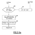
figure 2 est un organigramme représentant les étapes d'un mode de réalisation préféré du procédé d'évaluation des vibrations selon l'invention ; et, - la
figure 3 est une simulation informatique de l'image brute d'une étoile obtenue lors de la mise en oeuvre du procédé de lafigure 2 .
- the
figure 1 is a general schematic view of a satellite observing the Earth's surface; - the
figure 2 is a flowchart showing the steps of a preferred embodiment of the vibration evaluation method according to the invention; and, - the
figure 3 is a computer simulation of the raw image of a star obtained during the implementation of the method of thefigure 2 .
Dans la lignée des satellites SPOT, le projet PLEIADES constitue une nouvelle génération de satellites d'observation optique de la surface terrestre à haute résolution que la demanderesse a la charge de développer.In line with the SPOT satellites, the PLEIADES project is a new generation of optical observation satellites for the high resolution terrestrial surface that the applicant is in charge of developing.
En se référant à la
Le satellite 2 comporte un système imageur 7 pour l'acquisition d'images. Selon le projet PLEIADES, le système imageur 7 comprend un détecteur comportant une optique, pour collecter un flux lumineux, et deux capteurs du type CCD (« Charge-Coupled Device » ou capteur à couplage de charge) disposés dans le plan focal X, Y de l'optique. L'axe optique du système imageur 7, ou axe de visée, est confondu avec l'axe Z du repère de visée.The
Le premier capteur 8 du type CCD est constitué par une rangée de pixels alignés parallèlement à la première direction X. Ce premier capteur comporte environ 30 000 pixels de manière à offrir une haute résolution panchromatique. Le champ angulaire élémentaire couvert par ce premier détecteur est de 13 µrad selon la seconde direction Y du repère de visée.The first sensor 8 of the CCD type consists of a row of pixels aligned parallel to the first direction X. This first sensor comprises approximately 30,000 pixels so as to offer a high panchromatic resolution. The elementary angular field covered by this first detector is 13 μrad in the second direction Y of the sighting mark.
Le second détecteur 10 du type CCD est constitué par l'alignement de 7 500 pixels selon la première direction X. Ce second détecteur possède une résolution plus faible et un champ angulaire élémentaire de 4 µrad selon la seconde direction Y. Ce second détecteur est destiné à réaliser des images de la surface terrestre dans des bandes de longueur d'onde particulières.The
L'optique du système imageur 7 comporte des moyens adaptés pour que les rayons lumineux collectés soient incidents sur l'un et/ou sur l'autre des premier et second détecteurs 8, 10.The optics of the
Pour acquérir l'image d'un site terrestre, le satellite 2 reçoit, d'une station de contrôle au sol, un programme de mission comportant notamment un profil d'attitudes. Un profil d'attitudes est une succession temporelle de consignes d'attitude. Lors de l'exécution de ce programme de mission, les différentes consignes d'attitude sont appliquées séquentiellement en entrée du système d'attitude 6 du satellite 2 pour que celui-ci oriente convenablement le satellite 2 au cours de la prise de vue.To acquire the image of a terrestrial site, the
Plus précisément, mais tout en restant schématique, le profil d'attitudes comporte une position de pointage initiale et une vitesse de balayage. Pour simplifier la description qui va suivre, on repère les objets dans le plan XY. L'homme du métier connaît les transformations mathématiques qui permettent de passer d'un système de coordonnées à un autre.More precisely, but while remaining schematic, the attitude profile includes an initial pointing position and a scanning speed. To simplify the description that follows, we identify the objects in the XY plane. The person skilled in the art knows the mathematical transformations that make it possible to go from one coordinate system to another.
Ainsi, l'on considère que la position de pointage initiale est donnée par une première coordonnée Xi selon la première direction X et une seconde coordonnée Yi selon la seconde direction Y, et que la vitesse de balayage Ωi est donnée par une vitesse selon la seconde direction Y. Là encore, l'homme du métier comprendra que le système d'attitude du satellite peut être commandé de manière à réaliser une succession d'orientations plus complexe, en considérant que la vitesse angulaire Ωi est un vecteur de norme et d'orientation variables dans un repère inertiel.Thus, it is considered that the initial pointing position is given by a first coordinate X 1 in the first direction X and a second coordinate Y 1 in the second direction Y, and that the scanning speed Ω 1 is given by a speed according to the second Y direction. Here again, the skilled person will understand that the attitude system of the satellite can be controlled so as to achieve a more complex succession of orientations, considering that the angular velocity Ωi is a vector of norm and of variable orientation in an inertial reference.
Au début de la mission, le satellite est orienté de sorte que la position de pointage initiale Xi, Yi soit ramenée sur l'axe de visée Z, c'est-à-dire au centre du plan focal X, Y du système imageur. Puis, le satellite est orienté de manière à avoir une vitesse de balayage selon la seconde direction Y égale à Ωi pour balayer la surface au sol. La vitesse de balayage Ωi est adaptée pour qu'une bande élémentaire de la surface du sol, observée par le système imageur à un instant donné, et la bande élémentaire de la surface du sol voisine, observée par le système imageur à l'instant d'échantillonnage suivant, soient bord à bord. La juxtaposition de ces différentes bandes élémentaires permet d'obtenir, de proche en proche, une image de la surface du sol.At the beginning of the mission, the satellite is oriented so that the initial pointing position Xi, Yi is brought back to the line of sight Z, that is to say to the center of the focal plane X, Y of the imaging system. Then, the satellite is oriented to have a scanning speed in the second direction Y equal to Ωi to scan the ground surface. The scanning speed Ωi is adapted so that an elementary band of the surface of the ground, observed by the imaging system at a given instant, and the elementary band of the neighboring ground surface, observed by the imaging system at the instant of following sampling, be edge to edge. The juxtaposition of these different elementary bands makes it possible to obtain, step by step, an image of the surface of the ground.
Pour l'observation d'un site terrestre, la vitesse de balayage Ωi est fixée à une valeur qui tient compte de l'altitude de l'orbite 5. Elle est typiquement de 10 m rad/s.For the observation of a terrestrial site, the scanning speed Ωi is fixed at a value which takes into account the altitude of the
Le système d'attitude 6 du satellite 2 est muni d'actionneurs gyroscopiques. Le mouvement de rotation des toupies des actionneurs gyroscopiques à la vitesse de rotation ω génère des vibrations qui engendrent des variations temporelles de l'orientation de l'axe de visée Z autour de son orientation théorique.The
Le procédé selon l'invention permet d'évaluer les caractéristiques du mouvement de l'axe de visée Z en fonction de la vitesse de rotation ω des toupies. La vitesse de rotation des toupies est ensuite ajustée à la vitesse de rotation qui induit les plus faibles dégradations de la qualité des images de la surface du sol.The method according to the invention makes it possible to evaluate the characteristics of the movement of the sighting axis Z as a function of the speed of rotation ω of the rotors. The rotational speed of the rotors is then adjusted to the rotational speed which induces the smallest degradation of the quality of the images of the surface of the ground.
Selon l'invention, le satellite 2 exécute un programme de mission consistant à observer une étoile sélectionnée dont on connaît la position exacte tout en orientant le satellite avec une vitesse de balayage adaptée pour obtenir une image comportant, non pas une trace ponctuelle de l'étoile, mais une traînée selon la direction de balayage. La traînée présente des ondulations dont l'analyse permet d'évaluer les caractéristiques des vibrations.According to the invention, the
En se référant à la
Une table regroupe les étoiles qui sont observables par le système imageur 7 du satellite 2. Par exemple, il a été estimé que, compte tenu des caractéristiques physiques du système imageur 7, le premier capteur 8, haute résolution, du satellite PLEIADES permet d'observer des étoiles dont la magnitude est entre 1,8 et 6,7 et, de préférence, entre 2,2 et 4,3. En consultant les catalogues généraux répertoriant les étoiles et leurs caractéristiques, ce dernier intervalle de magnitude regroupe environ 340 étoiles. Il a été également estimé que le second capteur 10, basse résolution, permet d'observer des étoiles dont la magnitude est entre 1,2 et 6,6, et, de préférence, entre 2,2 et 6,0. Ce dernier intervalle représente environ 1 800 étoiles observables au moyen du second capteur.A table groups together the stars that are observable by the
Ainsi, à partir d'une extraction 50 des informations regroupées dans les catalogues d'étoiles 60, la table 70 des étoiles observables par le système imageur 7 du satellite 2 est établie et mémorisée dans une base de données.Thus, from an
Compte tenu par exemple de la position du satellite 2 le long de son orbite 5 au moment où sera exécuté le programme de mission, l'opérateur sélectionne à l'étape 100 une étoile particulière dans la table des étoiles observables.Given for example the position of the
Les deux coordonnées de position de l'étoile sélectionnée sont extraites de la table 70. On notera que la position d'une étoile sur la voûte céleste est donnée par deux coordonnées, par exemple une coordonnée de déclinaison et une autre d'ascension droite dans un système de coordonnées polaires. Comme indiqué ci-dessus, pour simplifier la description, on considère que les coordonnées de l'étoile sélectionnée sont une première coordonnée X0 selon la première direction X et une seconde coordonnée Y0 selon la seconde direction Y.The two position coordinates of the selected star are taken from the table 70. It will be noted that the position of a star on the celestial vault is given by two coordinates, for example a declination coordinate and a right ascension coordinate. a system of polar coordinates. As indicated above, to simplify the description, it is considered that the coordinates of the star selected are a first coordinate X0 in the first direction X and a second coordinate Y0 in the second direction Y.
A l'étape 200, l'opérateur détermine les paramètres permettant d'obtenir une image de l'étoile sélectionnée. Ainsi, pour une acquisition d'image de durée τ0, la vitesse de balayage Ω0 selon la seconde direction Y est choisie selon les deux critères suivants :
- pour être sûr que l'étoile sélectionnée se trouvera dans la fenêtre balayée lors de l'acquisition d'une image, la valeur de la vitesse de balayage Ω0 est choisie suffisamment élevée pour que le champ angulaire balayé à la vitesse de balayage Ω0 pendant la durée τ0 soit supérieur à la précision de pointage du système d'attitude du
satellite 2 ; - D'autre part, pour qu'un nombre suffisant de lignes de l'image obtenue présentent au moins un pixel ayant été éclairé par les photons de l'étoile sélectionnée, l'étoile sélectionnée doit traverser lentement le champ angulaire élémentaire du capteur 8,10. En conséquence, la valeur de la vitesse de balayage Ω0 est choisie suffisamment faible.
- to be sure that the selected star will be in the scanned window when acquiring an image, the value of the scanning speed Ω0 is chosen sufficiently high that the angular field scanned at scanning speed Ω0 during the duration τ0 is greater than the pointing accuracy of the
satellite attitude system 2; - On the other hand, for a sufficient number of lines of the image obtained to have at least one pixel having been illuminated by the photons of the selected star, the selected star must slowly traverse the elementary angular field of the
sensor 8, 10. As a result, the value of the scanning speed Ω0 is chosen sufficiently low.
Il s'agit donc de réaliser un compromis. En choisissant une vitesse de balayage Ω0 de 100 µrad/s et une durée τ0 de 3 secondes, le champ angulaire balayé selon la seconde direction Y sera de : Ω0 x τ0 = 300 µrad, ce qui est supérieur aux 30 µrad de la précision angulaire de pointage annoncée du système d'attitude du satellite PLEIADES. En s'affranchissant ainsi de la contrainte sur la précision de pointage, on est certain que l'image obtenue contiendra une trace de l'étoile sélectionnée. On notera que la vitesse Ω0 est ralentie par rapport à la vitesse de balayage lors de l'observation d'un site terrestre.It is therefore a question of making a compromise. By choosing a scanning speed Ω0 of 100 μrad / s and a duration τ0 of 3 seconds, the angular field scanned in the second direction Y will be: Ω0 x τ0 = 300 μrad, which is greater than 30 μrad of the angular precision Pointing System of the PLEIADES Satellite Attitude System. By thus avoiding the constraint on the pointing accuracy, it is certain that the image obtained will contain a trace of the selected star. It will be noted that the speed Ω0 is slowed down with respect to the scanning speed during the observation of a terrestrial site.
Simultanément, le nombre de lignes de l'image obtenue qui seront éclairées est égal au champ angulaire élémentaire du capteur 8, 10 divisé par le produit de la vitesse de balayage Ω0 par le temps d'échantillonnage t_ech. L'application numérique conduit à 1300 lignes éclairées pour une image obtenue au moyen du premier détecteur 8 haute résolution et à 400 lignes éclairées pour une image obtenue au moyen du second détecteur 10 faible résolution, le temps d'échantillonnage t_ech valant 0,1 ms.Simultaneously, the number of lines of the image obtained which will be illuminated is equal to the elementary angular field of the sensor 8, divided by the product of the scanning speed Ω0 by the sampling time t_ech. The digital application leads to 1300 illuminated lines for an image obtained by means of the first high-
Le profil d'attitudes du programme de mission est alors élaboré (étape 300). Il comporte une position de pointage initiale donnée par :
![]()
et une vitesse de balayage Ωi égale à Ω0.The attitude profile of the mission program is then developed (step 300). It has an initial pointing position given by:
![]()
and a scanning speed Ωi equal to Ω0.
Le programme de mission comporte également la durée τ0 de l'acquisition d'image en tant que paramètre à passer au système imageur 7, et la vitesse de rotation ω0 des toupies en tant que paramètre à passer au système d'attitude 6.The mission program also includes the duration τ0 of the image acquisition as a parameter to be passed to the
Une fois élaboré, le programme de mission est transmis au satellite.Once developed, the mission program is transmitted to the satellite.
Puis, avantageusement, alors que le satellite 2 se trouve dans la partie nuit d'une orbite, portion de l'orbite rarement utilisée pour réaliser des images de la surface terrestre, le programme de mission est exécuté.Then, advantageously, while the
Dans une première étape 400, la consigne ω0 de vitesse de rotation des toupies des actionneurs gyroscopiques est appliquée en entrée du système d'attitude 6. Celui-ci règle la vitesse de rotation des toupies à la consigne ω0 et indique lorsque la consigne demandée est atteinte.In a
Puis, à l'étape suivante 410, la séquence d'attitudes indiquée par le profil d'attitudes est réalisée. Le système d'attitude oriente le satellite pour que l'axe de visée Z pointe en direction de la position de pointage initiale Xi, Yi indiquée et que le satellite tourne à une vitesse correspondant à la vitesse de balayage Ωi indiquée.Then, in the
Simultanément et pendant une durée τ0, le système imageur 7 réalise une image par association des prises de vue élémentaires de la voûte céleste obtenues au cours du balayage de la fenêtre. Chaque prise de vue élémentaire correspond à l'observation de la voûte céleste à un instant donné avec le système imageur 7 ayant un champ angulaire élémentaire et un temps d'échantillonnage t_ech. La fenêtre s'étend autour de la seconde coordonnée Y0 de l'étoile sélectionnée, entre Y0-Ω0.τ0/2 et Y0+Ω0.τ0/2.Simultaneously and for a duration τ0, the
A l'issue de cette étape d'acquisition d'image, l'image obtenue 420 pour la vitesse de rotation de consigne ω0 des toupies est transmise à la station de contrôle au sol pour y être analysée (étapes 500 et 510) soit en temps réel, soit en temps différé.At the end of this image acquisition step, the obtained
Comme cela est représenté à la
La variation au cours du temps, c'est-à-dire selon la seconde direction Y, de la position selon la première direction X du pixel éclairé, ou du barycentre du groupe de pixels éclairés, est causée par l'oscillation de l'axe de visée Z sous l'action des vibrations. L'application d'un traitement statistique 500 sur la position selon la première direction X des pixels éclairés, par exemple du type calcul d'un écart à une position moyenne, conduit à une mesure de l'amplitude des vibrations pour la vitesse de rotation ω0 des toupies (étape 510). De plus, alors qu'il a été question de l'amplitude des vibrations dans ce qui précède, d'autres caractéristiques des vibrations peuvent être extraites de l'analyse des images d'étoile obtenues. Par exemple, une analyse en fréquence, du type analyse de Fourier, peut être pratiquée sur la traînée de l'étoile observée pour déterminer la fréquence, ou un spectre en fréquence, des vibrations.The variation over time, i.e. in the second direction Y, of the position along the first direction X of the illuminated pixel, or the center of gravity of the illuminated pixel group, is caused by the oscillation of the Z axis of view under the action of vibrations. The application of a
On notera que le procédé selon l'invention permet de caractériser les vibrations selon la première direction X uniquement. Mais, comme il s'agit d'un phénomène vibratoire n'ayant pas de direction privilégiée, cette mesure permet de caractériser les vibrations selon les trois axes.It will be noted that the method according to the invention makes it possible to characterize the vibrations according to the first direction X only. However, since this is a vibratory phenomenon that has no privileged direction, this measurement makes it possible to characterize the vibrations along the three axes.
En revenant à la
Après que plusieurs acquisitions d'image d'étoile ont été enchaînées pour une même vitesse de consigne ω0 des toupies, le programme de mission d'observation des étoiles prend fin. Le satellite peut être orienté vers la terre pour prendre des images de la surface terrestre.After several star image acquisitions have been chained for the same setpoint speed ω0 of the spinning tops, the star observation mission program ends. The satellite can be oriented towards the earth to take images of the earth's surface.
En effet, à cause du temps nécessaire pour que la vitesse de rotation d'une toupie d'un actionneur gyroscopique se stabilise à la valeur de consigne ω0, le procédé de caractérisation des vibrations est, de préférence, répété pour différentes valeurs de la vitesse de rotation ω des toupies au cours d'orbites différentes. Ainsi, la mesure de l'amplitude des vibrations pour une autre vitesse de rotation des toupies sera obtenue lors de la mise en oeuvre du procédé au cours de la partie nuit d'une autre orbite.Indeed, because of the time required for the rotational speed of a rotor of a gyroscopic actuator to stabilize at the setpoint ω0, the vibration characterization process is preferably repeated for different values of the speed. rotation ω spinning tops during orbits different. Thus, the measurement of the amplitude of the vibrations for another rotational speed of the rotors will be obtained during the implementation of the method during the night portion of another orbit.
De préférence, au cours d'une succession d'orbites, la valeur de la consigne ω0 est incrémentée à chaque orbite d'un pas prédéterminé Δω0 pour couvrir un intervalle d'intérêt entre une borne inférieure ωmin et une borne supérieure ωmax de vitesse de rotation ω des toupies.Preferably, during a succession of orbits, the value of the setpoint ω0 is incremented at each orbit by a predetermined pitch Δω0 to cover an interval of interest between a lower limit ωmin and an upper limit ωmax of rotation ω of the rotors.
A l'étape 600, la valeur actuelle de la consigne ω0 est comparée à la borne supérieure ωmax. Si la borne supérieure de l'intervalle d'intérêt n'est pas atteinte, à l'étape 610 la valeur de la consigne ω0 est incrémentée de Δω0 et le procédé est répété en réalisant un programme de mission adapté à cette nouvelle valeur de la consigne.In
Lorsque la borne supérieure ωmax de l'intervalle d'intérêt est atteinte, la dépendance entre l'amplitude des vibrations et la vitesse de rotation des toupies des actionneurs gyroscopiques est établie sur l'intervalle d'intérêt. La vitesse de rotation des toupies ω1 qui minimise les vibrations est déterminée à l'étape 620. Puis, à l'étape 630, la valeur ω1 est appliquée en tant que consigne au système d'attitude 6 du satellite 2 de manière à acquérir des images de la surface terrestre qui soient de qualité optimale.When the upper limit ωmax of the interval of interest is reached, the dependence between the amplitude of the vibrations and the speed of rotation of the rotors of the gyroscopic actuators is established on the interval of interest. The speed of rotation of the rotors ω1 which minimizes the vibrations is determined in
L'homme du métier constatera que le procédé selon l'invention permet l'évaluation des caractéristiques des vibrations directement sur une image obtenue par le système imageur, au moyen de traitements informatiques simples.Those skilled in the art will recognize that the method according to the invention makes it possible to evaluate the characteristics of the vibrations directly on an image obtained by the imaging system, by means of simple computer processes.
Le temps d'utilisation du satellite nécessaire pour la mise en oeuvre du procédé selon l'invention est compatible avec les temps morts normaux de l'utilisation d'un satellite.The time of use of the satellite necessary for the implementation of the method according to the invention is compatible with the normal dead time of the use of a satellite.
Puisque l'on ne cherche par à observer un point situé au sol qui pourrait être masqué par des nuages, le procédé selon l'invention peut être mis en oeuvre à n'importe quel instant. On s'affranchit ainsi des contraintes météorologiques.Since one does not seek to observe a point on the ground that could be masked by clouds, the method according to the invention can be implemented at any time. This eliminates meteorological constraints.
Des simulations de la mise en oeuvre du procédé selon l'invention indiquent que là où il fallait une dizaine de jours pour obtenir la dépendance de l'amplitude des vibrations en fonction de la vitesse de rotation des actionneurs gyroscopiques, il ne faut plus qu'une journée en mettant en oeuvre le procédé selon l'invention.Simulations of the implementation of the method according to the invention indicate that where it took about ten days to obtain the dependence of the amplitude of the vibrations as a function of the speed of rotation of the gyroscopic actuators, it is only necessary that a day by implementing the method according to the invention.
Si, dans le mode de réalisation actuellement préféré, le procédé selon l'invention permet l'évaluation des vibrations causées par le mouvement des toupies des actionneurs gyroscopiques, il peut également être mis en oeuvre pour évaluer des vibrations causées par d'autres dispositifs mécaniques embarqués à bord du satellite et ayant un ou plusieurs éléments mobiles dont les paramètres du mouvement, position ou vitesse, sont réglables. Il peut s'agir par exemple de roues à réaction, de moyens d'entraînement des panneaux solaires, de machines cryogéniques, etc.If, in the presently preferred embodiment, the method according to the invention makes it possible to evaluate the vibrations caused by the movement of the rotors of the gyroscopic actuators, it can also be used to evaluate vibrations caused by other mechanical devices. embedded on board the satellite and having one or more movable elements whose parameters of movement, position or speed, are adjustable. It may be, for example, reaction wheels, drive means for solar panels, cryogenic machines, etc.
Claims (11)
Applications Claiming Priority (1)
| Application Number | Priority Date | Filing Date | Title |
|---|---|---|---|
| FR0852960A FR2930820B1 (en) | 2008-04-30 | 2008-04-30 | VIBRATION CHARACTERIZATION METHOD FOR OBSERVATION SATELLITE |
Publications (2)
| Publication Number | Publication Date |
|---|---|
| EP2113460A1 true EP2113460A1 (en) | 2009-11-04 |
| EP2113460B1 EP2113460B1 (en) | 2012-02-01 |
Family
ID=39941861
Family Applications (1)
| Application Number | Title | Priority Date | Filing Date |
|---|---|---|---|
| EP09158935A Active EP2113460B1 (en) | 2008-04-30 | 2009-04-28 | Method for characterising vibrations for an observation satellite. |
Country Status (5)
| Country | Link |
|---|---|
| EP (1) | EP2113460B1 (en) |
| AT (1) | ATE543732T1 (en) |
| DK (1) | DK2113460T3 (en) |
| ES (1) | ES2379854T3 (en) |
| FR (1) | FR2930820B1 (en) |
Cited By (1)
| Publication number | Priority date | Publication date | Assignee | Title |
|---|---|---|---|---|
| WO2012076200A1 (en) * | 2010-12-10 | 2012-06-14 | Thales | Picture-capture instrument with autonomous pointing and observation satellite comprising such an instrument |
Families Citing this family (1)
| Publication number | Priority date | Publication date | Assignee | Title |
|---|---|---|---|---|
| CN113029318A (en) * | 2021-02-01 | 2021-06-25 | 中国人民解放军战略支援部队信息工程大学 | Satellite platform tremor detection and analysis method based on deep learning |
-
2008
- 2008-04-30 FR FR0852960A patent/FR2930820B1/en not_active Expired - Fee Related
-
2009
- 2009-04-28 DK DK09158935.8T patent/DK2113460T3/en active
- 2009-04-28 ES ES09158935T patent/ES2379854T3/en active Active
- 2009-04-28 AT AT09158935T patent/ATE543732T1/en active
- 2009-04-28 EP EP09158935A patent/EP2113460B1/en active Active
Non-Patent Citations (2)
| Title |
|---|
| JANSCHEK K ET AL: "Integrated camera motion compensation by real-time image motion tracking and image deconvolution", ADVANCED INTELLIGENT MECHATRONICS. PROCEEDINGS, 2005 IEEE/ASME INTERNA TIONAL CONFERENCE ON MONTEREY, CA JULY 24-28, 2005, PISCATAWAY, NJ, USA,IEEE, 24 July 2005 (2005-07-24), pages 1437 - 1444, XP010837963, ISBN: 978-0-7803-9047-8 * |
| ROQUES S ET AL: "Satellite attitude instability effects on stereo images", ACOUSTICS, SPEECH, AND SIGNAL PROCESSING, 2004. PROCEEDINGS. (ICASSP ' 04). IEEE INTERNATIONAL CONFERENCE ON MONTREAL, QUEBEC, CANADA 17-21 MAY 2004, PISCATAWAY, NJ, USA,IEEE, vol. 3, 17 May 2004 (2004-05-17), pages 477 - 480, XP010718230, ISBN: 978-0-7803-8484-2 * |
Cited By (1)
| Publication number | Priority date | Publication date | Assignee | Title |
|---|---|---|---|---|
| WO2012076200A1 (en) * | 2010-12-10 | 2012-06-14 | Thales | Picture-capture instrument with autonomous pointing and observation satellite comprising such an instrument |
Also Published As
| Publication number | Publication date |
|---|---|
| EP2113460B1 (en) | 2012-02-01 |
| ES2379854T3 (en) | 2012-05-04 |
| DK2113460T3 (en) | 2012-04-23 |
| FR2930820B1 (en) | 2010-06-04 |
| ATE543732T1 (en) | 2012-02-15 |
| FR2930820A1 (en) | 2009-11-06 |
Similar Documents
| Publication | Publication Date | Title |
|---|---|---|
| EP1843295B1 (en) | Method of recreating the movements of the line of sight of an optical instrument | |
| EP1580524B1 (en) | Method and device for characterising structural damage using moiré shadows | |
| EP1298592B1 (en) | Stabilizing images of a scene, gray level offset correction, moving object detection and adjustment of two image pickup devices based on image stabilization | |
| FR2653875A1 (en) | METHOD FOR DETERMINING THE POSITION OF A MACHINE BY ACQUISITION AND IDENTIFICATION OF STARS. | |
| EP2495531B1 (en) | Method for measuring the stability of a line of sight and corresponding star sensor | |
| FR2938072A1 (en) | METHOD FOR PROCESSING SIGNALS OF AN AIRBORNE RADAR WITH RADAR BEAM CORRECTION CORRECTION CORRECTION CORRECTION AND CORRESPONDING DEVICE | |
| EP2593367B1 (en) | Space surveillance system for surveying the near space | |
| WO2017190951A1 (en) | Self-calibrating and autonomous magnetic observatory | |
| EP0777128A1 (en) | Method and device for attitude measurement of a satellite | |
| EP2113460B1 (en) | Method for characterising vibrations for an observation satellite. | |
| EP0790505A1 (en) | Slotted sun sensor | |
| WO2023089275A1 (en) | Process for the acquisition of images of a space object in terrestrial orbit by a spacecraft in terrestrial orbit | |
| EP0608945B1 (en) | Star sensor with CCD-array, method of detection and application to reposition a spacecraft | |
| CN111598810B (en) | Method and system for sensing and recovering degradation information of rotating optical satellite image | |
| Copândean et al. | Asteroids detection tehnique: Classic “blink”: An automated approch | |
| EP3018625B1 (en) | Method for calibrating a sight system | |
| EP4185532A1 (en) | Method and system for detecting one or more targets in space based on images taken from a spacecraft such as a visual inspection satellite, and satellite equipped with such a system | |
| FR2701762A1 (en) | Device for restoring the orbit of celestial bodies, particularly artificial satellites, by means of deviation. | |
| EP2733929B1 (en) | Method and system for the real-time determination of a number of signals to be summed | |
| EP2672302B1 (en) | Method for correcting thermo-elastic effects in a space telescope and space telescope using this method | |
| FR2699679A1 (en) | Method and device for the radiographic analysis of moving objects | |
| Hellmich et al. | Harvesting large astronomical data archives for space debris observations | |
| EP3847622B1 (en) | Measurement of land surface albedo, without needing a conventional albedometer | |
| Copândean | PhD Student: PhD Supervisor | |
| WO2023148455A1 (en) | Device, method and program for recording radiofrequency activity of artificial satellites |
Legal Events
| Date | Code | Title | Description |
|---|---|---|---|
| PUAI | Public reference made under article 153(3) epc to a published international application that has entered the european phase |
Free format text: ORIGINAL CODE: 0009012 |
|
| AK | Designated contracting states |
Kind code of ref document: A1 Designated state(s): AT BE BG CH CY CZ DE DK EE ES FI FR GB GR HR HU IE IS IT LI LT LU LV MC MK MT NL NO PL PT RO SE SI SK TR |
|
| 17P | Request for examination filed |
Effective date: 20100413 |
|
| 17Q | First examination report despatched |
Effective date: 20100528 |
|
| GRAP | Despatch of communication of intention to grant a patent |
Free format text: ORIGINAL CODE: EPIDOSNIGR1 |
|
| GRAS | Grant fee paid |
Free format text: ORIGINAL CODE: EPIDOSNIGR3 |
|
| GRAA | (expected) grant |
Free format text: ORIGINAL CODE: 0009210 |
|
| AK | Designated contracting states |
Kind code of ref document: B1 Designated state(s): AT BE BG CH CY CZ DE DK EE ES FI FR GB GR HR HU IE IS IT LI LT LU LV MC MK MT NL NO PL PT RO SE SI SK TR |
|
| REG | Reference to a national code |
Ref country code: GB Ref legal event code: FG4D Free format text: NOT ENGLISH |
|
| REG | Reference to a national code |
Ref country code: AT Ref legal event code: REF Ref document number: 543732 Country of ref document: AT Kind code of ref document: T Effective date: 20120215 Ref country code: CH Ref legal event code: EP |
|
| REG | Reference to a national code |
Ref country code: DE Ref legal event code: R096 Ref document number: 602009004990 Country of ref document: DE Effective date: 20120329 |
|
| REG | Reference to a national code |
Ref country code: DK Ref legal event code: T3 |
|
| REG | Reference to a national code |
Ref country code: ES Ref legal event code: FG2A Ref document number: 2379854 Country of ref document: ES Kind code of ref document: T3 Effective date: 20120504 |
|
| REG | Reference to a national code |
Ref country code: NL Ref legal event code: VDEP Effective date: 20120201 |
|
| LTIE | Lt: invalidation of european patent or patent extension |
Effective date: 20120201 |
|
| PG25 | Lapsed in a contracting state [announced via postgrant information from national office to epo] |
Ref country code: IS Free format text: LAPSE BECAUSE OF FAILURE TO SUBMIT A TRANSLATION OF THE DESCRIPTION OR TO PAY THE FEE WITHIN THE PRESCRIBED TIME-LIMIT Effective date: 20120601 Ref country code: LT Free format text: LAPSE BECAUSE OF FAILURE TO SUBMIT A TRANSLATION OF THE DESCRIPTION OR TO PAY THE FEE WITHIN THE PRESCRIBED TIME-LIMIT Effective date: 20120201 Ref country code: NO Free format text: LAPSE BECAUSE OF FAILURE TO SUBMIT A TRANSLATION OF THE DESCRIPTION OR TO PAY THE FEE WITHIN THE PRESCRIBED TIME-LIMIT Effective date: 20120501 Ref country code: HR Free format text: LAPSE BECAUSE OF FAILURE TO SUBMIT A TRANSLATION OF THE DESCRIPTION OR TO PAY THE FEE WITHIN THE PRESCRIBED TIME-LIMIT Effective date: 20120201 Ref country code: NL Free format text: LAPSE BECAUSE OF FAILURE TO SUBMIT A TRANSLATION OF THE DESCRIPTION OR TO PAY THE FEE WITHIN THE PRESCRIBED TIME-LIMIT Effective date: 20120201 |
|
| REG | Reference to a national code |
Ref country code: IE Ref legal event code: FD4D |
|
| PG25 | Lapsed in a contracting state [announced via postgrant information from national office to epo] |
Ref country code: PT Free format text: LAPSE BECAUSE OF FAILURE TO SUBMIT A TRANSLATION OF THE DESCRIPTION OR TO PAY THE FEE WITHIN THE PRESCRIBED TIME-LIMIT Effective date: 20120601 Ref country code: PL Free format text: LAPSE BECAUSE OF FAILURE TO SUBMIT A TRANSLATION OF THE DESCRIPTION OR TO PAY THE FEE WITHIN THE PRESCRIBED TIME-LIMIT Effective date: 20120201 Ref country code: GR Free format text: LAPSE BECAUSE OF FAILURE TO SUBMIT A TRANSLATION OF THE DESCRIPTION OR TO PAY THE FEE WITHIN THE PRESCRIBED TIME-LIMIT Effective date: 20120502 Ref country code: FI Free format text: LAPSE BECAUSE OF FAILURE TO SUBMIT A TRANSLATION OF THE DESCRIPTION OR TO PAY THE FEE WITHIN THE PRESCRIBED TIME-LIMIT Effective date: 20120201 Ref country code: LV Free format text: LAPSE BECAUSE OF FAILURE TO SUBMIT A TRANSLATION OF THE DESCRIPTION OR TO PAY THE FEE WITHIN THE PRESCRIBED TIME-LIMIT Effective date: 20120201 |
|
| REG | Reference to a national code |
Ref country code: AT Ref legal event code: MK05 Ref document number: 543732 Country of ref document: AT Kind code of ref document: T Effective date: 20120201 |
|
| PG25 | Lapsed in a contracting state [announced via postgrant information from national office to epo] |
Ref country code: CY Free format text: LAPSE BECAUSE OF FAILURE TO SUBMIT A TRANSLATION OF THE DESCRIPTION OR TO PAY THE FEE WITHIN THE PRESCRIBED TIME-LIMIT Effective date: 20120201 |
|
| BERE | Be: lapsed |
Owner name: CENTRE NATIONAL D'ETUDES SPATIALES Effective date: 20120430 |
|
| PG25 | Lapsed in a contracting state [announced via postgrant information from national office to epo] |
Ref country code: SE Free format text: LAPSE BECAUSE OF FAILURE TO SUBMIT A TRANSLATION OF THE DESCRIPTION OR TO PAY THE FEE WITHIN THE PRESCRIBED TIME-LIMIT Effective date: 20120201 Ref country code: CZ Free format text: LAPSE BECAUSE OF FAILURE TO SUBMIT A TRANSLATION OF THE DESCRIPTION OR TO PAY THE FEE WITHIN THE PRESCRIBED TIME-LIMIT Effective date: 20120201 Ref country code: IE Free format text: LAPSE BECAUSE OF FAILURE TO SUBMIT A TRANSLATION OF THE DESCRIPTION OR TO PAY THE FEE WITHIN THE PRESCRIBED TIME-LIMIT Effective date: 20120201 Ref country code: RO Free format text: LAPSE BECAUSE OF FAILURE TO SUBMIT A TRANSLATION OF THE DESCRIPTION OR TO PAY THE FEE WITHIN THE PRESCRIBED TIME-LIMIT Effective date: 20120201 Ref country code: SI Free format text: LAPSE BECAUSE OF FAILURE TO SUBMIT A TRANSLATION OF THE DESCRIPTION OR TO PAY THE FEE WITHIN THE PRESCRIBED TIME-LIMIT Effective date: 20120201 Ref country code: EE Free format text: LAPSE BECAUSE OF FAILURE TO SUBMIT A TRANSLATION OF THE DESCRIPTION OR TO PAY THE FEE WITHIN THE PRESCRIBED TIME-LIMIT Effective date: 20120201 |
|
| PG25 | Lapsed in a contracting state [announced via postgrant information from national office to epo] |
Ref country code: SK Free format text: LAPSE BECAUSE OF FAILURE TO SUBMIT A TRANSLATION OF THE DESCRIPTION OR TO PAY THE FEE WITHIN THE PRESCRIBED TIME-LIMIT Effective date: 20120201 Ref country code: MC Free format text: LAPSE BECAUSE OF NON-PAYMENT OF DUE FEES Effective date: 20120430 |
|
| PLBE | No opposition filed within time limit |
Free format text: ORIGINAL CODE: 0009261 |
|
| STAA | Information on the status of an ep patent application or granted ep patent |
Free format text: STATUS: NO OPPOSITION FILED WITHIN TIME LIMIT |
|
| 26N | No opposition filed |
Effective date: 20121105 |
|
| PG25 | Lapsed in a contracting state [announced via postgrant information from national office to epo] |
Ref country code: BE Free format text: LAPSE BECAUSE OF NON-PAYMENT OF DUE FEES Effective date: 20120430 Ref country code: AT Free format text: LAPSE BECAUSE OF FAILURE TO SUBMIT A TRANSLATION OF THE DESCRIPTION OR TO PAY THE FEE WITHIN THE PRESCRIBED TIME-LIMIT Effective date: 20120201 |
|
| PG25 | Lapsed in a contracting state [announced via postgrant information from national office to epo] |
Ref country code: MK Free format text: LAPSE BECAUSE OF FAILURE TO SUBMIT A TRANSLATION OF THE DESCRIPTION OR TO PAY THE FEE WITHIN THE PRESCRIBED TIME-LIMIT Effective date: 20120201 |
|
| REG | Reference to a national code |
Ref country code: DE Ref legal event code: R097 Ref document number: 602009004990 Country of ref document: DE Effective date: 20121105 |
|
| PG25 | Lapsed in a contracting state [announced via postgrant information from national office to epo] |
Ref country code: MT Free format text: LAPSE BECAUSE OF FAILURE TO SUBMIT A TRANSLATION OF THE DESCRIPTION OR TO PAY THE FEE WITHIN THE PRESCRIBED TIME-LIMIT Effective date: 20120201 Ref country code: BG Free format text: LAPSE BECAUSE OF FAILURE TO SUBMIT A TRANSLATION OF THE DESCRIPTION OR TO PAY THE FEE WITHIN THE PRESCRIBED TIME-LIMIT Effective date: 20120501 |
|
| REG | Reference to a national code |
Ref country code: CH Ref legal event code: PL |
|
| PG25 | Lapsed in a contracting state [announced via postgrant information from national office to epo] |
Ref country code: LI Free format text: LAPSE BECAUSE OF NON-PAYMENT OF DUE FEES Effective date: 20130430 Ref country code: CH Free format text: LAPSE BECAUSE OF NON-PAYMENT OF DUE FEES Effective date: 20130430 |
|
| PG25 | Lapsed in a contracting state [announced via postgrant information from national office to epo] |
Ref country code: TR Free format text: LAPSE BECAUSE OF FAILURE TO SUBMIT A TRANSLATION OF THE DESCRIPTION OR TO PAY THE FEE WITHIN THE PRESCRIBED TIME-LIMIT Effective date: 20120201 |
|
| PG25 | Lapsed in a contracting state [announced via postgrant information from national office to epo] |
Ref country code: LU Free format text: LAPSE BECAUSE OF NON-PAYMENT OF DUE FEES Effective date: 20120428 |
|
| PG25 | Lapsed in a contracting state [announced via postgrant information from national office to epo] |
Ref country code: HU Free format text: LAPSE BECAUSE OF FAILURE TO SUBMIT A TRANSLATION OF THE DESCRIPTION OR TO PAY THE FEE WITHIN THE PRESCRIBED TIME-LIMIT Effective date: 20090428 |
|
| REG | Reference to a national code |
Ref country code: FR Ref legal event code: PLFP Year of fee payment: 8 |
|
| REG | Reference to a national code |
Ref country code: FR Ref legal event code: PLFP Year of fee payment: 9 |
|
| REG | Reference to a national code |
Ref country code: FR Ref legal event code: PLFP Year of fee payment: 10 |
|
| PGFP | Annual fee paid to national office [announced via postgrant information from national office to epo] |
Ref country code: FR Payment date: 20230315 Year of fee payment: 15 Ref country code: DK Payment date: 20230327 Year of fee payment: 15 |
|
| PGFP | Annual fee paid to national office [announced via postgrant information from national office to epo] |
Ref country code: IT Payment date: 20230412 Year of fee payment: 15 Ref country code: ES Payment date: 20230504 Year of fee payment: 15 Ref country code: DE Payment date: 20230316 Year of fee payment: 15 |
|
| PGFP | Annual fee paid to national office [announced via postgrant information from national office to epo] |
Ref country code: GB Payment date: 20230502 Year of fee payment: 15 |