EP0777128A1 - Method and device for attitude measurement of a satellite - Google Patents
Method and device for attitude measurement of a satellite Download PDFInfo
- Publication number
- EP0777128A1 EP0777128A1 EP96402579A EP96402579A EP0777128A1 EP 0777128 A1 EP0777128 A1 EP 0777128A1 EP 96402579 A EP96402579 A EP 96402579A EP 96402579 A EP96402579 A EP 96402579A EP 0777128 A1 EP0777128 A1 EP 0777128A1
- Authority
- EP
- European Patent Office
- Prior art keywords
- attitude
- satellite
- gps
- measurement
- antennas
- Prior art date
- Legal status (The legal status is an assumption and is not a legal conclusion. Google has not performed a legal analysis and makes no representation as to the accuracy of the status listed.)
- Granted
Links
- 238000005259 measurement Methods 0.000 title claims abstract description 60
- 238000000034 method Methods 0.000 title claims description 13
- 235000019892 Stellar Nutrition 0.000 claims abstract description 22
- 238000005305 interferometry Methods 0.000 claims abstract description 22
- 230000010363 phase shift Effects 0.000 claims abstract description 7
- 238000004364 calculation method Methods 0.000 claims description 21
- 238000012545 processing Methods 0.000 claims description 3
- 238000013178 mathematical model Methods 0.000 claims 1
- 239000011159 matrix material Substances 0.000 description 34
- 239000013598 vector Substances 0.000 description 14
- 238000004422 calculation algorithm Methods 0.000 description 5
- 230000006870 function Effects 0.000 description 5
- 238000010586 diagram Methods 0.000 description 3
- 230000000694 effects Effects 0.000 description 3
- 230000004438 eyesight Effects 0.000 description 3
- 201000004569 Blindness Diseases 0.000 description 2
- 101100406879 Neurospora crassa (strain ATCC 24698 / 74-OR23-1A / CBS 708.71 / DSM 1257 / FGSC 987) par-2 gene Proteins 0.000 description 2
- 230000003287 optical effect Effects 0.000 description 2
- 230000000717 retained effect Effects 0.000 description 2
- 230000007704 transition Effects 0.000 description 2
- BYHQTRFJOGIQAO-GOSISDBHSA-N 3-(4-bromophenyl)-8-[(2R)-2-hydroxypropyl]-1-[(3-methoxyphenyl)methyl]-1,3,8-triazaspiro[4.5]decan-2-one Chemical compound C[C@H](CN1CCC2(CC1)CN(C(=O)N2CC3=CC(=CC=C3)OC)C4=CC=C(C=C4)Br)O BYHQTRFJOGIQAO-GOSISDBHSA-N 0.000 description 1
- 241000897276 Termes Species 0.000 description 1
- 238000012937 correction Methods 0.000 description 1
- 230000007547 defect Effects 0.000 description 1
- 238000009795 derivation Methods 0.000 description 1
- 238000001514 detection method Methods 0.000 description 1
- 238000001914 filtration Methods 0.000 description 1
- 230000004313 glare Effects 0.000 description 1
- 238000005286 illumination Methods 0.000 description 1
- 238000002513 implantation Methods 0.000 description 1
- 238000009434 installation Methods 0.000 description 1
- 101150093826 par1 gene Proteins 0.000 description 1
- 238000010587 phase diagram Methods 0.000 description 1
- 238000012360 testing method Methods 0.000 description 1
Images

Classifications
-
- G—PHYSICS
- G01—MEASURING; TESTING
- G01S—RADIO DIRECTION-FINDING; RADIO NAVIGATION; DETERMINING DISTANCE OR VELOCITY BY USE OF RADIO WAVES; LOCATING OR PRESENCE-DETECTING BY USE OF THE REFLECTION OR RERADIATION OF RADIO WAVES; ANALOGOUS ARRANGEMENTS USING OTHER WAVES
- G01S19/00—Satellite radio beacon positioning systems; Determining position, velocity or attitude using signals transmitted by such systems
- G01S19/38—Determining a navigation solution using signals transmitted by a satellite radio beacon positioning system
- G01S19/39—Determining a navigation solution using signals transmitted by a satellite radio beacon positioning system the satellite radio beacon positioning system transmitting time-stamped messages, e.g. GPS [Global Positioning System], GLONASS [Global Orbiting Navigation Satellite System] or GALILEO
- G01S19/53—Determining attitude
- G01S19/54—Determining attitude using carrier phase measurements; using long or short baseline interferometry
-
- B—PERFORMING OPERATIONS; TRANSPORTING
- B64—AIRCRAFT; AVIATION; COSMONAUTICS
- B64G—COSMONAUTICS; VEHICLES OR EQUIPMENT THEREFOR
- B64G1/00—Cosmonautic vehicles
- B64G1/22—Parts of, or equipment specially adapted for fitting in or to, cosmonautic vehicles
- B64G1/24—Guiding or controlling apparatus, e.g. for attitude control
- B64G1/244—Spacecraft control systems
-
- G—PHYSICS
- G01—MEASURING; TESTING
- G01S—RADIO DIRECTION-FINDING; RADIO NAVIGATION; DETERMINING DISTANCE OR VELOCITY BY USE OF RADIO WAVES; LOCATING OR PRESENCE-DETECTING BY USE OF THE REFLECTION OR RERADIATION OF RADIO WAVES; ANALOGOUS ARRANGEMENTS USING OTHER WAVES
- G01S19/00—Satellite radio beacon positioning systems; Determining position, velocity or attitude using signals transmitted by such systems
- G01S19/01—Satellite radio beacon positioning systems transmitting time-stamped messages, e.g. GPS [Global Positioning System], GLONASS [Global Orbiting Navigation Satellite System] or GALILEO
- G01S19/13—Receivers
- G01S19/14—Receivers specially adapted for specific applications
-
- G—PHYSICS
- G01—MEASURING; TESTING
- G01S—RADIO DIRECTION-FINDING; RADIO NAVIGATION; DETERMINING DISTANCE OR VELOCITY BY USE OF RADIO WAVES; LOCATING OR PRESENCE-DETECTING BY USE OF THE REFLECTION OR RERADIATION OF RADIO WAVES; ANALOGOUS ARRANGEMENTS USING OTHER WAVES
- G01S19/00—Satellite radio beacon positioning systems; Determining position, velocity or attitude using signals transmitted by such systems
- G01S19/01—Satellite radio beacon positioning systems transmitting time-stamped messages, e.g. GPS [Global Positioning System], GLONASS [Global Orbiting Navigation Satellite System] or GALILEO
- G01S19/13—Receivers
- G01S19/23—Testing, monitoring, correcting or calibrating of receiver elements
-
- G—PHYSICS
- G01—MEASURING; TESTING
- G01S—RADIO DIRECTION-FINDING; RADIO NAVIGATION; DETERMINING DISTANCE OR VELOCITY BY USE OF RADIO WAVES; LOCATING OR PRESENCE-DETECTING BY USE OF THE REFLECTION OR RERADIATION OF RADIO WAVES; ANALOGOUS ARRANGEMENTS USING OTHER WAVES
- G01S3/00—Direction-finders for determining the direction from which infrasonic, sonic, ultrasonic, or electromagnetic waves, or particle emission, not having a directional significance, are being received
- G01S3/78—Direction-finders for determining the direction from which infrasonic, sonic, ultrasonic, or electromagnetic waves, or particle emission, not having a directional significance, are being received using electromagnetic waves other than radio waves
- G01S3/782—Systems for determining direction or deviation from predetermined direction
- G01S3/785—Systems for determining direction or deviation from predetermined direction using adjustment of orientation of directivity characteristics of a detector or detector system to give a desired condition of signal derived from that detector or detector system
- G01S3/786—Systems for determining direction or deviation from predetermined direction using adjustment of orientation of directivity characteristics of a detector or detector system to give a desired condition of signal derived from that detector or detector system the desired condition being maintained automatically
- G01S3/7867—Star trackers
Definitions
- the present invention relates to a device and a method for measuring the attitude of a terrestrial satellite in a reference trihedron. It finds a particularly important application in the case of satellites placed in low orbit, between 400 km and 1400 km altitude.
- the attitude of satellites is measured using optical sensors of stars (sensors of terrestrial or solar horizon, stellar sensors).
- stellar sensors have the advantage of high precision.
- the devices comprising a star sensor have the disadvantage of being blind when the sensor is facing a star hole, or when it is dazzled by a star constituting an intense light source.
- the device can be provided with gyroscopes for this purpose. They provide a reference during periods of blindness, but do not allow an absolute measurement and have a drift.
- the present invention aims in particular to provide an attitude measurement device comprising, in addition to one or more star sensors, means making it possible to maintain a measurement accuracy that is not degraded during periods of blindness.
- the invention proposes in particular a device placed on the satellite, having n non-aligned antennas (n being at least equal to three) for receiving radio frequency signals from several satellites of a global positioning system by satellites (so-called GPS system), means for processing radio frequency signals received by the different antennas, measuring their phase shift and calculating attitude from said phase shifts, and means for repetitively calibrating the measurement and calculation means based on measurements made using the stellar sensor during the periods when this the latter provides usable data.
- n being at least equal to three
- a satellite At altitudes between 400 and 1400 km, a satellite is always in direct view of at least three GPS satellites, which allows a permanent attitude measurement.
- a measurement made only from signals received from GPS satellites would have a much lower accuracy than that obtained using a star sensor.
- the measurement and calculation means can be calibrated on the basis of the information provided by the star sensor. The device then makes it possible to obtain, during star holes or glare, an accuracy almost equal to that provided from data supplied by the stellar sensor.
- GPS also makes it possible to rule out a defect in the devices using a stellar sensor, alone or in combination with a gyroscope, which is the need for an initial procedure for recognizing constellations in the field of the sensor.
- the use of GPS makes it possible to know at any time the position of the satellite, its speed vector and the time.
- the GPS also makes it possible to know the initial attitude with sufficient precision to identify the stars which are in the field of the sensor and eliminate the need for a search for constellations.
- the spacing between the antennas for receiving radio frequency signals from GPS satellites is generally much greater than the wavelength (about 20 cm) of radio frequency signals provided by GPS satellites.
- An initial ambiguity can therefore exist on the attitude, because the phase shift is only measured modulo 2 ⁇ .
- Doubt can be removed in several ways.
- the satellite acquisition mode can be such as the accuracy of the initial pointing is sufficient so that there is no ambiguity.
- the number n of antennas may be sufficient for the doubt to be resolved by performing a correlation between several attitude measurements each carried out using a distinct set of three antennas.
- the information provided by the magnetometer which is generally provided with a satellite placed in the Earth's magnetic field allows a rough attitude measurement, but sufficient to remove the doubt.
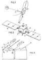
- FIG. 2 shows a possible constitution of a satellite 10 whose attitude with respect to the earth has to be determined.
- This satellite comprises a body 12 and solar panels 14.
- a star sensor 16 On the body is placed a star sensor 16 having a wide angular field.
- This star sensor can be completed by a terrestrial or solar horizon sensor.
- a stellar sensor 16 with a large field.
- Such a sensor has the advantage of allowing detection only on the basis of stars having a low magnitude, less than four for example.
- the catalog of stars to be memorized does not exceed 300 stars, which facilitates management and authorizes image processing on board the satellite.
- the body 12 of the satellite also carries at least three antennas for receiving the signals transmitted by the GPS satellites.
- the antennas 18 are provided, at the four corners of the body of the satellite so as to have maximum precision.
- each attitude measurement by GPS interferometry can be made using a set of three antennas only. By carrying out several measurements, each time with a set of three different antennas, one can increase the accuracy and also carry out doubt surveys.
- each antenna 18 with a mask which limits the angle at the top of the reception cone to a value less than 180 °, for example 140 °.
- the number of satellites in direct view varies, over a period of twelve hours, between three and eight with such a mask.
- Figure 3 shows the principle of attitude measurement by interferometry from the signals supplied by two GPS antennas.
- the phase shift between the signals supplied by the two antennas 18 1 and 18 2 depends on the orientation of the base b (line connecting 18 1 and 18 2 ) with respect to the direction defined by a unit vector s j of the incident wave from a GPS satellite of order j.
- the number of possible measurements is equal to the product of the number of GPS satellites simultaneously visible by the number of antenna bases available.
- these antennas are grouped so that one constitutes a master antenna, forming a common reference, and each of the others a slave antenna.
- ⁇ ij constitutes an error term, due essentially to multiple paths, different for each base and each GPS satellite. This term evolves slowly over time. Consequently, a value calculated by calibration using the stellar sensor can be kept for a blind period which follows.
- each path difference is made up of the scalar product of the base vector of antennas b i and of the unit vector s j of signal direction (satellite vector - GPS satellite observed).
- This scalar product involves the rotation matrix between the satellite reference point and the terrestrial reference point in which the outputs of the GPS receiver are given. It therefore suffices from two antenna bases, therefore from three antennas, and from two GPS satellites to determine the attitude along three axes of the satellite.
- the acquisition procedure guarantees a score better than 10 ° to rule out the problem. Otherwise, the ambiguity can be removed by comparing the results provided by a large number of bases.
- a first source is constituted by the multiple paths such as those shown in FIG. 3. This effect, linked to the use of radio frequencies, is reproducible.
- the attitude of the satellite can be defined by the matrix A of passage from the satellite frame of reference Xs Ys Zs to the orbital frame of reference XYZ.
- the set of measurements for several antenna bases and several GPS satellites provides a system of equations with three unknowns, the number of which is overabundant. For small deflection angles, these equations are linear and allow a solution by the method of least squares. In practice, it is always possible to reduce this situation by an appropriate choice of the reference frame XsYsZs linked to the satellite.
- the necessary measurements can be made using a multiplexer which makes it possible to successively connect each of the antennas to a measurement chain comprising a receiver, a correlator involving the phase and quadrature components of the signal and, for each slave antenna, a differential filter. phase which provides a phase difference.
- the angular velocity r can also be calculated.
- the measurement by GPS interferometry can be carried out at a high rate but the accuracy of the attitude measurement by GPS interferometry alone is limited to a value which may be insufficient. For example, it is around 0.5 ° to 3 ° for a GPS system alone and a satellite of the kind defined above. This limitation is notably due to the existence of multiple paths, differences between cable bias of link and differences between the phase centers of the GPS antennas.
- the last two sources of error can be calibrated once and for all.
- Accuracy can be significantly improved by taking into account the error due to multiple paths by repeated calibrations using the star sensor, which achieves an accuracy of about 0.15 ° on its line of sight and maintain almost equal accuracy by GPS interferometry and calibration.
- the sensor can be of a known matrix type, which therefore need not be described. It receives the angles identifying the pointing ⁇ n obtained during the previous measurement of order n and includes a selection logic 40 intended to choose a group of three stars for each calculation, from among the many stars contained in the field of vision of the sensor. 16 ( Figure 2).
- a first test 48 is carried out on the number of visible stars. If it is less than 2, no measurement is carried out and the hand passes to the system 50 of attitude calculation by GSM interferometry.
- step 52 allows you to select three stars; for example the three stars chosen can be either the three brightest, or the brightest star and those which have the greatest angular difference between them and with the brightest star.
- the computer 54 itself comprises, at the input, a member or a step 56 for choosing the windows of the field of vision to be analyzed for each star selected. It provides, at the output, a half-width of window of angular extent ⁇ u i for each of the stars retained, of position u i .
- the detector comprises a CCD matrix whose photosensitive sites are read in each of the three windows, each extending from u i - ⁇ u i to u i + ⁇ u i , thus providing illumination signals E for all the photosensitive sites. in each window.
- a classical calculation of the barycenter of each spot corresponding to a star provides an estimated value û i , generally different from u i and due to the difference between the input value ⁇ s and the real value for which an estimate is sought. ⁇ ⁇ s.
- the coherence of the measurements can be determined by applying in 58 an algorithm for evaluating a coherence index using as a reference the memorized characteristics of the star observed and making it possible to rule out errors due to the presence of another satellite or from a distant planet in the field of vision.
- the index obtained is compared with a threshold.
- the matrix R is formed of the terms R ii ; which are functions of the magnitude M i of the star measured and the direction measured û i ; we can also give it a value which is a function of ⁇ ', that is to say the scrolling speed.
- the product B. ⁇ u provides the attitude increment ⁇ which is added to the original value ⁇ S and provides an estimate ⁇ ⁇ S which will be used in place of ⁇ for the next measurement and will be used to recalibrate the measurement device by GPS interferometry. In order to obtain sufficient accuracy, a measurement rate of at least 8 Hz is generally required.
- the algorithm for selecting between measurement by GPS interferometry and measurement using the stellar sensor can be that shown diagrammatically in FIG. 5, assuming an initial coarse measurement already available, for example by a three-axis magnetometer. The measurement is carried out by star sensor, except in cases where it is not possible. The results of the measurement, whatever the mode used, are re-entered at the input.
- block 62 designates all of the means shown in Figure 4 and which provide the angles defining the attitude (which will be designated as a whole by ⁇ e to differentiate them from the angles ⁇ g obtained by GPS interferometry) and the rotation matrix A.
- phase differences ⁇ ij are calculated in 68 for all the bases b i .
- the least squares resolution will provide a and c.
- the attitude matrix is then the product of A by the transition matrix from the local orbital frame to the inertial frame marked inv (Rol.In) and the angles ⁇ x, ⁇ y, ⁇ z are then determined by identification.
- the calculation steps can be those summarized in Figure 8, with the usual mathematical notations.
Landscapes
- Engineering & Computer Science (AREA)
- Remote Sensing (AREA)
- Radar, Positioning & Navigation (AREA)
- Computer Networks & Wireless Communication (AREA)
- Physics & Mathematics (AREA)
- General Physics & Mathematics (AREA)
- Automation & Control Theory (AREA)
- Chemical & Material Sciences (AREA)
- Combustion & Propulsion (AREA)
- Aviation & Aerospace Engineering (AREA)
- Position Fixing By Use Of Radio Waves (AREA)
- Navigation (AREA)
Abstract
Description
La présente invention a pour objet un dispositif et un procédé de mesure d'attitude d'un satellite terrestre dans un trièdre de référence. Elle trouve une application particulièrement importante dans le cas des satellites placés en orbite basse, entre 400 km et 1400 km d'altitude.The present invention relates to a device and a method for measuring the attitude of a terrestrial satellite in a reference trihedron. It finds a particularly important application in the case of satellites placed in low orbit, between 400 km and 1400 km altitude.
A l'heure actuelle, on mesure l'attitude des satellites en utilisant des capteurs optiques d'astres (capteurs d'horizon terrestre ou solaire, capteurs stellaires). Parmi ces dispositifs, les capteurs stellaires ont l'avantage d'une précision élevée. En contrepartie, les dispositifs comportant un capteur stellaire présentent l'inconvénient d'être aveugles lorsque le capteur est face à un trou d'étoiles, ou lorsqu'il est ébloui par un astre constituant une source de lumière intense.At present, the attitude of satellites is measured using optical sensors of stars (sensors of terrestrial or solar horizon, stellar sensors). Among these devices, stellar sensors have the advantage of high precision. In return, the devices comprising a star sensor have the disadvantage of being blind when the sensor is facing a star hole, or when it is dazzled by a star constituting an intense light source.
Il est nécessaire de conserver une mesure d'attitude du satellite même pendant les périodes où le capteur optique est aveugle, notamment pour pouvoir commander l'attitude au cours de ces périodes, qui peuvent aller jusqu'à 5 % du temps sur un satellite en orbite basse. on peut munir à cet effet le dispositif de gyroscopes. Ils fournissent une référence pendant les périodes d'aveuglement, mais ne permettent pas une mesure absolue et ont une dérive.It is necessary to keep a satellite attitude measurement even during the periods when the optical sensor is blind, in particular to be able to control the attitude during these periods, which can be up to 5% of the time on a satellite in low orbit. the device can be provided with gyroscopes for this purpose. They provide a reference during periods of blindness, but do not allow an absolute measurement and have a drift.
La présente invention vise notamment à fournir un dispositif de mesure d'attitude comportant, en plus d'un ou de plusieurs capteurs d'astres, des moyens permettant de conserver une précision de mesure peu dégradée pendant les périodes d'aveuglement.The present invention aims in particular to provide an attitude measurement device comprising, in addition to one or more star sensors, means making it possible to maintain a measurement accuracy that is not degraded during periods of blindness.
Dans ce but, l'invention propose notamment un dispositif placé sur le satellite, ayant n antennes non alignées (n étant au moins égal à trois) de réception de signaux à radio-fréquence provenant de plusieurs satellites d'un système de positionnement global par satellites (système dit GPS), des moyens de traitement des signaux à radio-fréquence reçus par les différentes antennes, de mesure de leur déphasage et de calcul d'attitude à partir desdits déphasages, et des moyens de calibrage répétitif des moyens de mesure et de calcul à partir de mesures effectuées à l'aide du capteur stellaire pendant les périodes où ce dernier fournit des données utilisables.To this end, the invention proposes in particular a device placed on the satellite, having n non-aligned antennas (n being at least equal to three) for receiving radio frequency signals from several satellites of a global positioning system by satellites (so-called GPS system), means for processing radio frequency signals received by the different antennas, measuring their phase shift and calculating attitude from said phase shifts, and means for repetitively calibrating the measurement and calculation means based on measurements made using the stellar sensor during the periods when this the latter provides usable data.
Aux altitudes comprises entre 400 et 1400 km, un satellite est toujours en vue directe d'au moins trois satellites GPS, ce qui permet une mesure d'attitude permanente.At altitudes between 400 and 1400 km, a satellite is always in direct view of at least three GPS satellites, which allows a permanent attitude measurement.
Une mesure faite uniquement à partir des signaux reçus des satellites GPS aurait une précision nettement inférieure à celle obtenue à l'aide d'un capteur d'astres. Mais on peut calibrer les moyens de mesure et de calcul à partir des informations fournies par le capteur stellaire. Le dispositif permet alors d'obtenir, pendant les trous d'étoile ou les éblouissements, une précision presque égale à celle fournie à partir de données fournies par le capteur stellaire.A measurement made only from signals received from GPS satellites would have a much lower accuracy than that obtained using a star sensor. However, the measurement and calculation means can be calibrated on the basis of the information provided by the star sensor. The device then makes it possible to obtain, during star holes or glare, an accuracy almost equal to that provided from data supplied by the stellar sensor.
Le recours au GPS permet de plus d'écarter un défaut des dispositifs utilisant un capteur stellaire, seul ou en association avec un gyroscope, qui est la nécessité d'une procédure initiale de reconnaissance de constellations dans le champ du capteur. En effet, le recours au GPS permet de connaître à tout moment la position du satellite, son vecteur vitesse et l'heure. Le GPS permet de plus de connaître l'attitude initiale avec une précision suffisante pour identifier les étoiles qui se trouvent dans le champ du capteur et supprimer la nécessité d'une recherche de constellations.The use of GPS also makes it possible to rule out a defect in the devices using a stellar sensor, alone or in combination with a gyroscope, which is the need for an initial procedure for recognizing constellations in the field of the sensor. Indeed, the use of GPS makes it possible to know at any time the position of the satellite, its speed vector and the time. The GPS also makes it possible to know the initial attitude with sufficient precision to identify the stars which are in the field of the sensor and eliminate the need for a search for constellations.
L'écartement entre les antennes de réception des signaux à radio-fréquence provenant des satellites GPS est en général nettement supérieur à la longueur d'onde (environ 20 cm) des signaux radio-fréquence, fournis par les satellites GPS. Une ambiguité initiale peut donc exister sur l'attitude, du fait que le déphasage n'est mesuré que modulo 2π. Le doute peut être levé de plusieurs façons. Le mode d'acquisition du satellite peut être tel que la précision du pointage initial soit suffisante pour qu'il n'y ait pas d'ambiguité. Le nombre n d'antennes peut être suffisant pour que le doute puisse être levé en effectuant une corrélation entre plusieurs mesures d'attitude effectuées chacune en utilisant un jeu distinct de trois antennes. Enfin, les informations fournies par le magnétomètre dont est généralement muni un satellite placé dans le champ magnétique terrestre permettent une mesure d'attitude grossière, mais suffisante pour lever le doute.The spacing between the antennas for receiving radio frequency signals from GPS satellites is generally much greater than the wavelength (about 20 cm) of radio frequency signals provided by GPS satellites. An initial ambiguity can therefore exist on the attitude, because the phase shift is only measured modulo 2π. Doubt can be removed in several ways. The satellite acquisition mode can be such as the accuracy of the initial pointing is sufficient so that there is no ambiguity. The number n of antennas may be sufficient for the doubt to be resolved by performing a correlation between several attitude measurements each carried out using a distinct set of three antennas. Finally, the information provided by the magnetometer which is generally provided with a satellite placed in the Earth's magnetic field allows a rough attitude measurement, but sufficient to remove the doubt.
Les caractéristiques ci-dessus et d'autres apparaîtront mieux à la lecture de la description qui suit d'un mode particulier de réalisation, donné à titre d'exemple non limitatif. La description se réfère aux dessins qui l'accompagnent, dans lesquels :
- la figure 1 est un schéma de principe montrant les paramètres qui permettent de définir l'attitude d'un satellite placé sur une orbite terrestre ;
- la figure 2 montre une implantation possible d'un capteur stellaire et d'antennes GPS sur un satellite, permettant de mettre en oeuvre l'invention ;
- la figure 3 est un schéma de principe de la mesure d'attitude d'un satellite par interférométrie GSM, faisant également apparaître l'effet de trajets multiples ;
- la figure 4 est un organigramme montrant les étapes d'un calcul d'attitude à l'aide d'un capteur stellaire ;
- la figure 5 est un organigramme de l'algorithme de sélection entre modes de mesure d'attitude ;
- la figure 6 est un organigramme de principe, indiquant la séquence d'opérations permettant d'effectuer une mesure fine d'attitude, par calibrage des moyens utilisant le système GPS.
- la figure 7 est un organigramme détaillant l'algorithme de calibration des moyens de calcul d'attitude par interférométrie GPS, à l'aide du capteur stellaire ;
- la figure 8 détaille la séquence des calculs. Habituellement, on cherche à connaître l'attitude d'un satellite par rapport à un trièdre de référence lié à l'orbite, ou repère orbital local. La figure 1 montre un tel trièdre de référence, constitué par un axe Z pointé vers la terre, un axe Y normal au plan de l'orbite et un axe X dans le sens de la vitesse. L'attitude du satellite peut alors être définie par la matrice de passage d'un trièdre lié au satellite, au repère orbital local XYZ. Ce trièdre lié au satellite peut notamment comporter un axe Ys orthogonal à deux faces (nord et sud d'un satellite sur orbite équatoriale par exemple), un axe Zs (dont l'orientation de consigne est vers la terre dans le cas fréquent d'un pointage géocentrique) et un axe Xs orthogonal aux deux précédents.
- FIG. 1 is a block diagram showing the parameters which make it possible to define the attitude of a satellite placed in a terrestrial orbit;
- FIG. 2 shows a possible installation of a star sensor and GPS antennas on a satellite, making it possible to implement the invention;
- FIG. 3 is a block diagram of the attitude measurement of a satellite by GSM interferometry, also showing the effect of multiple paths;
- FIG. 4 is a flowchart showing the steps of an attitude calculation using a stellar sensor;
- FIG. 5 is a flowchart of the algorithm for selecting between attitude measurement modes;
- FIG. 6 is a flow diagram in principle, indicating the sequence of operations making it possible to carry out a fine measurement of attitude, by calibrating the means using the GPS system.
- FIG. 7 is a flowchart detailing the algorithm for calibrating the attitude calculation means by GPS interferometry, using the stellar sensor;
- Figure 8 details the sequence of calculations. Usually, we seek to know the attitude of a satellite with respect to a reference trihedron linked to the orbit, or local orbital coordinate system. Figure 1 shows such a reference trihedron, consisting of a Z axis pointing towards the earth, a Y axis normal to the plane of the orbit and an X axis in the direction of speed. The attitude of the satellite can then be defined by the passage matrix of a trihedron linked to the satellite, to the local orbital coordinate system XYZ. This trihedron linked to the satellite can in particular comprise an axis Ys orthogonal with two faces (north and south of a satellite in equatorial orbit for example), an axis Zs (whose orientation of reference is towards the earth in the frequent case a geocentric pointing) and an Xs axis orthogonal to the previous two.
La figure 2 montre une constitution possible d'un satellite 10 dont l'attitude par rapport à la terre doit être déterminée. Ce satellite comporte un corps 12 et des panneaux solaires 14. Sur le corps est placé un capteur stellaire 16 ayant un champ angulaire étendu. Ce capteur stellaire peut être complété par un capteur d'horizon terrestre ou solaire.FIG. 2 shows a possible constitution of a
Pour la mise en oeuvre de l'invention, on peut notamment utiliser un capteur stellaire 16 à grand champ. Un champ de 30 x 30°, ou plus généralement compris entre 25 x 25° et 35 x 35° est généralement bien approprié. Il permet une mesure d'attitude suivant trois axes dès qu'au moins deux étoiles sont dans le champ de vue. Un tel capteur présente l'avantage d'autoriser la détection uniquement sur la base des étoiles ayant une magnitude faible, inférieure à quatre par exemple. Ainsi le catalogue d'étoiles à mémoriser ne dépasse pas 300 étoiles, ce qui facilite la gestion et autorise le traitement de l'image à bord du satellite.For the implementation of the invention, it is possible in particular to use a
Conformément à l'invention, le corps 12 du satellite porte également au moins trois antennes de réception des signaux émis par les satellites GPS. Dans le cas illustré sur la figure 2, quatre antennes 18 sont prévues, aux quatre coins du corps du satellite de façon à avoir une précision maximale. Comme on le verra plus loin, chaque mesure d'attitude par interférométrie GPS peut être faite en utilisant un jeu de trois antennes seulement. En effectuant plusieurs mesures, chaque fois avec un jeu de trois antennes différent, on peut augmenter la précision et également effectuer des levés de doute.According to the invention, the
Pour réduire les effets de trajets multiples provoqués par des réflexions des signaux hyperfréquence GPS, il est avantageux de munir chaque antenne 18 d'un masque qui limite l'angle au sommet du cône de réception à une valeur inférieure à 180°, par exemple de 140°. Dans le cas d'un satellite placé sur une orbite basse (entre 400 et 1400 km d'altitude), le nombre de satellites en vue directe varie, sur une période de douze heures, entre trois et huit avec un tel masque.To reduce the effects of multiple paths caused by reflections of the GPS microwave signals, it is advantageous to provide each
La figure 3 montre le principe de la mesure d'attitude par interférométrie à partir des signaux fournis par deux antennes GPS. Le déphasage entre les signaux fournis par les deux antennes 181 et 182 dépend de l'orientation de la base b (ligne reliant 181 et 182) par rapport à la direction définie par un vecteur unitaire sj de l'onde incidente provenant d'un satellite GPS d'ordre j. Le nombre de mesures possibles est égal au produit du nombre de satellites GPS simultanément visibles par le nombre de bases d'antennes disponibles. Souvent, on regroupe ces antennes de façon que l'une constitue une antenne maître, formant une référence commune, et chacune des autres une antenne esclave.Figure 3 shows the principle of attitude measurement by interferometry from the signals supplied by two GPS antennas. The phase shift between the signals supplied by the two
Avec les notations suivantes :
- bi :
- base d'antenne d'ordre i,
- B =
- (b1,···, bi, ...),
- sj :
- vecteur unitaire du signal incident pour le satellite GPS d'ordre j,
- S =
- (S1, ···, Sj, ···)
- A :
- matrice de rotation de passage du repère de consigne au repère satellite,
- ΔΦij:
- différence de phase entre deux antennes, pour la porteuse provenant du satellite GPS d'ordre j,
- λ :
- longueur d'onde de la porteuse GPS considérée,
- δΦij:
- perturbation due aux multi-trajets différentiels entre les deux antennes de la base (différence entre diagrammes de phase) pour la base i et le satellite j,
- bij :
- bruit pour la base i et le satellite GPS d'ordre j,
- Bo =
- (b11, ..., bij, ...).
- b i :
- antenna base of order i,
- B =
- (b 1 , ···, b i , ...),
- s j :
- unit vector of the incident signal for the GPS satellite of order j,
- S =
- (S 1 , ···, S j , ···)
- AT :
- rotation matrix for moving from the set point to the satellite point,
- ΔΦ ij :
- phase difference between two antennas, for the carrier coming from the GPS satellite of order j,
- λ:
- wavelength of the GPS carrier considered,
- δΦ ij :
- perturbation due to differential multipaths between the two antennas of the base (difference between phase diagrams) for base i and satellite j,
- b ij :
- noise for base i and GPS satellite of order j,
- B o =
- (b 11 , ..., b ij , ...).
on a :![]()
![]()
Dans cette formule (1), δΦij constitue un terme d'erreur, dû essentiellement aux trajets multiples, différent pour chaque base et chaque satellite GPS. Ce terme évolue, lentement dans le temps. En conséquence, une valeur calculée par calibrage à l'aide du capteur stellaire peut être conservée pendant une période d'aveuglement qui suit.In this formula (1), δΦ ij constitutes an error term, due essentially to multiple paths, different for each base and each GPS satellite. This term evolves slowly over time. Consequently, a value calculated by calibration using the stellar sensor can be kept for a blind period which follows.
En posant :![]()
![]()
on peut écrire :we can write :
R = BTA.S, en prenant en compte l'ensemble des mesures.R = B T AS, taking into account all the measurements.
Dès que trois satellites GPS sont visibles, on peut inverser les matrices B et S dans le plan des antennes GPS avec un algorithme de type des moindres carrés et obtenir la matrice de rotation A :![]()
![]()
La matrice A peut ensuite être complétée en dehors du plan des antennes en utilisant la relation :![]()
caractéristique des rotations.The matrix A can then be completed outside the plane of the antennas using the relation: ![]()
characteristic of rotations.
on voit qu'à partir de la connaissance des bases bi et de la différence de phase entre antennes GPS pour chacun des satellites GPS visibles, on peut mesurer l'attitude. Chaque différence de marche est constituée par le produit scalaire du vecteur base d'antennes bi et du vecteur unitaire sj de la direction du signal (vecteur satellite - satellite GPS observé). Ce produit scalaire fait intervenir la matrice de rotation entre le repère satellite et le repère terrestre dans lequel sont données les sorties du récepteur GPS. Il suffit donc de deux bases d'antennes, donc de trois antennes, et de deux satellites GPS pour déterminer l'attitude suivant trois axes du satellite.we see that from knowing the bases b i and the phase difference between GPS antennas for each of the visible GPS satellites, we can measure the attitude. Each path difference is made up of the scalar product of the base vector of antennas b i and of the unit vector s j of signal direction (satellite vector - GPS satellite observed). This scalar product involves the rotation matrix between the satellite reference point and the terrestrial reference point in which the outputs of the GPS receiver are given. It therefore suffices from two antenna bases, therefore from three antennas, and from two GPS satellites to determine the attitude along three axes of the satellite.
Toutefois, il existe une ambiguité sur chaque mesure, qui ne peut être levée qu'en connaissant le nombre de longueurs d'onde de la porteuse entre les mesures des deux antennes GPS de la base considérée. Ce problème se pose dès que l'incertitude sur le pointage dépasse 10° pour |bi| = 1 m et λ = 0,20 m.However, there is an ambiguity on each measurement, which can only be resolved by knowing the number of wavelengths of the carrier between the measurements of the two GPS antennas of the base considered. This problem arises as soon as the pointing uncertainty exceeds 10 ° for | b i | = 1 m and λ = 0.20 m.
Il suffit en conséquence que la procédure d'acquisition garantisse un pointage meilleur que 10° pour écarter le problème. Dans le cas contraire, l'ambiguité peut être levée par comparaison entre les résultats fournis par un nombre élevé de bases.It is therefore sufficient that the acquisition procedure guarantees a score better than 10 ° to rule out the problem. Otherwise, the ambiguity can be removed by comparing the results provided by a large number of bases.
La précision obtenue par interférométrie GPS seule est limitée par des sources d'erreur.The accuracy obtained by GPS interferometry alone is limited by sources of error.
Une première source est constituée par les trajets multiples tels que ceux montrés sur la figure 3. Cet effet, lié à l'emploi de radio-fréquences, est reproductible.A first source is constituted by the multiple paths such as those shown in FIG. 3. This effect, linked to the use of radio frequencies, is reproducible.
D'autres sources de bruit, tels que des différentiels entre biais de câbles, entre centres de phase des antennes GPS, entre alignement des antennes, peuvent être assimilés aux bruits dûs aux trajets multiples.Other sources of noise, such as differentials between cable bias, between phase centers of GPS antennas, between antenna alignment, can be assimilated to noise due to multipath.
Enfin, il existe un bruit de mesure, essentiellement dû au bruit thermique des antennes.Finally, there is measurement noise, mainly due to the thermal noise of the antennas.
Toutes ces sources de bruit limitent la précision qu'il serait possible d'atteindre, par utilisation du système GPS seul, à une valeur de l'ordre de 0,5°, même avec un filtrage temporel sur plusieurs minutes.All these noise sources limit the precision that it would be possible to achieve, by using the GPS system alone, to a value of the order of 0.5 °, even with time filtering over several minutes.
L'emploi, en combinaison, de l'interférométrie GPS et d'un capteur stellaire permet d'obtenir une précision de l'ordre de celle du capteur stellaire pendant les périodes où ce dernier est inutilisable.The use, in combination, of GPS interferometry and a stellar sensor makes it possible to obtain an accuracy of the order of that of the stellar sensor during the periods where the latter is unusable.
Avant de décrire le mode de mesure d'attitude à partir des informations fournies par le capteur stellaire et le calibrage des moyens de mesure par interféromètre GPS, on définira plus complètement un mode de calcul d'attitude par interférométrie GSM.Before describing the attitude measurement mode from the information provided by the star sensor and the calibration of the measurement means by GPS interferometer, a mode of attitude calculation by GSM interferometry will be more completely defined.
Comme déjà indiqué, l'attitude du satellite peut être définie par la matrice A de passage du repère satellite Xs Ys Zs au repère orbital XYZ.As already indicated, the attitude of the satellite can be defined by the matrix A of passage from the satellite frame of reference Xs Ys Zs to the orbital frame of reference XYZ.
Pour une base d'antennes définie par ![]()
![]()
![]()
![]()
Un récepteur associé aux antennes 181 et 182 constituant la base i permet de mesurer la différence de phase ΔΦ puis, à un nombre entier k de longueurs d'onde λ près, est :![]()
![]()
L'ensemble des mesures pour plusieurs bases d'antennes et plusieurs satellites GPS fournit un système d'équations à trois inconnues dont le nombre est surabondant. Pour des angles de dépointage faibles, ces équations sont linéaires et permettent une résolution par la méthode des moindres carrés. Dans la pratique, il est toujours possible de se ramener à cette situation par un choix approprié du repère XsYsZs lié au satellite.The set of measurements for several antenna bases and several GPS satellites provides a system of equations with three unknowns, the number of which is overabundant. For small deflection angles, these equations are linear and allow a solution by the method of least squares. In practice, it is always possible to reduce this situation by an appropriate choice of the reference frame XsYsZs linked to the satellite.
Si on désigne par :

![]()

![]()
![]()
![]()
Si on désigne par H la matrice d'observation :![]()
![]()
![]()
![]()
Avec quatre antennes GPS, dont une est utilisée comme antenne maître, on dispose de trois bases. Les mesures nécessaires peuvent être faites en utilisant un multiplexeur qui permet de relier successivement chacune des antennes à une chaîne de mesure comportant un récepteur, un corrélateur faisant intervenir les composantes en phase et en quadrature du signal et, pour chaque antenne esclave, un filtre différentiel de phase qui fournit une différence de phase.With four GPS antennas, one of which is used as the master antenna, there are three bases. The necessary measurements can be made using a multiplexer which makes it possible to successively connect each of the antennas to a measurement chain comprising a receiver, a correlator involving the phase and quadrature components of the signal and, for each slave antenna, a differential filter. phase which provides a phase difference.
Il faut noter au passage que les erreurs dues aux antennes 18 (différences de retard par exemple) sont communes à tous les satellites GPS. Il est donc facile de les prendre en compte.It should be noted in passing that the errors due to the antennas 18 (delay differences for example) are common to all GPS satellites. It is therefore easy to take them into account.
Pour résoudre le système d'équations (dont le nombre nxm est le produit du nombre n de bases par le nombre m de satellites GPS utilisés) par la méthode des moindres carrés, on cherche la valeur ![]()

![]()
Il est avantageux de donner à chaque mesure un poids proportionnel à //bi Λ ![]()
![]()
![]()
![]()
![]()
![]()
![]()
![]()
Par dérivation, à l'aide de deux mesures successives qui donnent ![]()
![]()
![]()
![]()
La mesure par interférométrie GPS peut être effectuée à cadence élevée mais la précision de la mesure d'attitude par interféromètrie GPS seule est limitée à une valeur qui peut être insuffisante. Par exemple, elle est d'environ 0,5° à 3° pour un système GPS seul et un satellite du genre défini plus haut. Cette limitation est notamment due à l'existence de trajets multiples, des différences entre biais de câble de liaison et des différences entre les centres de phase des antennes GPS.The measurement by GPS interferometry can be carried out at a high rate but the accuracy of the attitude measurement by GPS interferometry alone is limited to a value which may be insufficient. For example, it is around 0.5 ° to 3 ° for a GPS system alone and a satellite of the kind defined above. This limitation is notably due to the existence of multiple paths, differences between cable bias of link and differences between the phase centers of the GPS antennas.
Les deux dernières sources d'erreur peuvent être étalonnées une fois pour toutes.The last two sources of error can be calibrated once and for all.
La précision peut être notablement améliorée en tenant compte de l'erreur due aux trajets multiples par des calibrages répétés à l'aide du capteur d'étoiles, qui permet d'atteindre une précision de 0,15° environ sur son axe de visée et de maintenir une précision presque égale par interféromètrie GPS et calibrage.Accuracy can be significantly improved by taking into account the error due to multiple paths by repeated calibrations using the star sensor, which achieves an accuracy of about 0.15 ° on its line of sight and maintain almost equal accuracy by GPS interferometry and calibration.
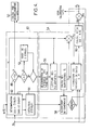
Avant de décrire le mode de calibrage, il peut être utile d'indiquer un processus possible de mesure d'attitude par un capteur stellaire. Celui montré en figure 4 est utilisable si le pointage initial θ du satellite est connu avec une approximation suffisante pour qu'une reconnaissance de constellation soit inutile.Before describing the calibration mode, it may be useful to indicate a possible process of attitude measurement by a star sensor. The one shown in FIG. 4 can be used if the initial pointing θ of the satellite is known with a sufficient approximation for a constellation recognition to be useless.
Le capteur peut être d'un type matriciel connu, qu'il n'est donc pas nécessaire de décrire. Il reçoit les angles identifiant le pointage θn obtenus lors de la mesure précédente d'ordre n et comporte une logique de sélection 40 destinée à choisir un groupe de trois étoiles pour chaque calcul, parmi les nombreuses étoiles contenues dans le champ de vision du capteur 16 (figure 2).The sensor can be of a known matrix type, which therefore need not be described. It receives the angles identifying the pointing θ n obtained during the previous measurement of order n and includes a
L'organe d'entrée de la logique 40 est un élément 42 de reconnaissance des étoiles observées, par référence à un catalogue contenu dans une mémoire morte 44. Il fournit, en sortie,
- les positions angulaires ui présumées des étoiles observées, déduites du catalogue,
- les valeurs Mi des magnitudes de ces étoiles, dans la mesure où il en est tenu compte,
- the assumed angular positions u i of the stars observed, deduced from the catalog,
- the values M i of the magnitudes of these stars, to the extent that this is taken into account,
Un premier test 48 est effectué sur le nombre d'étoiles visibles. S'il est inférieur à 2, aucune mesure n'est effectuée et la main passe au système 50 de calcul d'attitude par interférométrie GSM.A
Si le nombre d'étoiles dépasse 3, une autre étape 52 permet de sélectionner trois étoiles ; par exemple les trois étoiles choisies peuvent être soit les trois plus brillantes, soit l'étoile la plus brillante et celles qui ont le plus grand écart angulaire entre elles et avec l'étoile la plus brillante.If the number of stars exceeds 3, another
Le calculateur proprement dit 54 comporte, en entrée, un organe ou une étape 56 de choix des fenêtres du champ de vision à analyser pour chaque étoile sélectionnée. Il fournit, en sortie, une demi-largeur de fenêtre d'étendue angulaire Δui pour chacune des étoiles retenues, de position ui.The
Typiquement, le détecteur comporte une matrice CCD dont les sites photosensibles sont lus dans chacune des trois fenêtres, s'étendant chacune de ui-Δui à ui+Δui, fournissant ainsi des signaux d'éclairement E pour tous les sites photosensibles dans chaque fenêtre. Un calcul classique de barycentre de chaque tache correspondant à une étoile fournit une valeur estimée ûi, généralement différente de ui et due à l'écart entre la valeur θs d'entrée et la valeur réelle dont on cherche une estimée ![]()
![]()
La cohérence des mesures peut être déterminée en appliquant en 58 un algorithme d'évaluation d'un indice de cohérence utilisant comme référence les caractéristiques mémorisées de l'étoile observée et permettant d'écarter les erreurs dues à la présence d'un autre satellite ou d'une planète lointaine dans le champ de vision. L'indice obtenu est comparé avec un seuil.The coherence of the measurements can be determined by applying in 58 an algorithm for evaluating a coherence index using as a reference the memorized characteristics of the star observed and making it possible to rule out errors due to the presence of another satellite or from a distant planet in the field of vision. The index obtained is compared with a threshold.
Les résultats ûi retenus sont utilisés pour former la matrice A de rotation et la matrice R déjà définie par la formule (2) ci-dessus.The results û i retained are used to form the matrix A of rotation and the matrix R already defined by formula (2) above.
La matrice A est formée des éléments -ûi, c'est-à-dire des éléments matriciels, qui représentent les rotations autour du vecteur ![]()
![]()
![]()
![]()
La matrice R est formée des termes Rii; qui sont fonctions de la magnitude Mi de l'étoile mesurée et de la direction mesurée ûi ; on peut également lui donner une valeur fonction de θ', c'est-à-dire de la vitesse de défilement.![]()
avec rii = f(Mi, û
pour i = 1, 2 ou 3 en général.The matrix R is formed of the terms R ii ; which are functions of the magnitude M i of the star measured and the direction measured û i ; we can also give it a value which is a function of θ ', that is to say the scrolling speed. ![]()
with r ii = f (M i , û
for i = 1, 2 or 3 in general.
Enfin, on calcule des valeurs δui correspondant chacune à la différence entre une position prédite à partir du catalogue ui et la position effective estimée ûi obtenue par la mesure.Finally, we calculate values δu i each corresponding to the difference between a predicted position from the catalog u i and the estimated actual position û i obtained by the measurement.
Au cours d'une étape suivante de calcul, en 60, on calcule la matrice R-1 = (...,1/rii,...) qu'on peut considérer comme la matrice inverse de la matrice de covariance des bruits. En première approximation, c'est une matrice diagonale, ce qui minimise les opérations. Il devient alors possible de calculer B qui est la matrice principale du problème. C'est la matrice qui permet de définir le vecteur des différences entre l'attitude prédite et l'attitude mesurée.During a following calculation step, in 60, we calculate the matrix R -1 = (..., 1 / r ii , ...) which can be considered as the inverse matrix of the covariance matrix of noises. As a first approximation, it is a diagonal matrix, which minimizes the operations. It then becomes possible to calculate B which is the main matrix of the problem. It is the matrix which makes it possible to define the vector of the differences between the predicted attitude and the measured attitude.
Le produit B.δu fournit l'incrément d'attitude δθ qui est ajouté à la valeur d'origine θS et fournit une estimation ![]()
![]()
L'algorithme de sélection entre mesure par interférométrie GPS et mesure à l'aide du capteur stellaire peut être celui schématisé en figure 5, en supposant une mesure grossière initiale déjà disponible, par exemple par magnétomètre trois axes. La mesure est effectuée par capteur stellaire, sauf dans les cas où elle n'est pas possible. Les résultats de la mesure, quel que soit le mode utilisé, sont ré-introduits à l'entrée.The algorithm for selecting between measurement by GPS interferometry and measurement using the stellar sensor can be that shown diagrammatically in FIG. 5, assuming an initial coarse measurement already available, for example by a three-axis magnetometer. The measurement is carried out by star sensor, except in cases where it is not possible. The results of the measurement, whatever the mode used, are re-entered at the input.
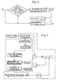
Enfin on décrira, en faisant référence à la figure 6, le mode de calibration du dispositif de mesure par interférométrie GPS. Sur cette figure, le bloc 62 désigne l'ensemble des moyens montrés en figure 4 et qui fournissent les angles définissant l'attitude (qu'on désignera dans leur ensemble par θe pour les différencier des angles θg obtenus par interférométrie GPS) et la matrice de rotation A.Finally, with reference to FIG. 6, the mode of calibration of the measurement device by GPS interferometry will be described. In this figure, block 62 designates all of the means shown in Figure 4 and which provide the angles defining the attitude (which will be designated as a whole by θ e to differentiate them from the angles θ g obtained by GPS interferometry) and the rotation matrix A.
Le récepteur GPS, relié séquentiellement aux différentes antennes, fournit :
- la position P et la vitesse V du satellite, et l'heure T,
- l'orientation des satellites GPS,
- les phases φ pour les différentes antennes et les différents satellites correspondant aux vecteurs unitaires sj.
- the position P and the speed V of the satellite, and the time T,
- orientation of GPS satellites,
- the phases φ for the different antennas and the different satellites corresponding to the unit vectors s j .
A partir de là, et grâce au multiplexage permettant de comparer les phases φ, on calcule en 68 les différences de phase Δφij pour toutes les bases bi. En 66, les vecteurs unitaires ![]()
![]()
![]()
![]()
Les différences de parcours déjà définies sont, elles, calculées à partir des valeurs Δφ et donnent naissance à une matrice Δr.The course differences already defined are calculated from the Δφ values and give rise to a Δr matrix.
Un bloc séparé 70 permet de disposer du vecteur des bases d'antennes![]()
![]()
A partir de là, par la formule (3) ci-dessus, on peut obtenir A qui s'écrit également, dans le plan des antennes :![]()
![]()
De la matrice A dans le plan des antennes, on peut déduire la matrice de rotation hors de ce plan (formule 4). La connaissance de A permet en conséquence de calculer les angles d'attitude, désignés par θg pour les différencier de ceux obtenus à l'aide du capteur stellaire.From the matrix A in the plane of the antennas, we can deduce the rotation matrix outside this plane (formula 4). Knowledge of A therefore makes it possible to calculate the angles of attitude, designated by θg to differentiate them from those obtained using the stellar sensor.
Le calcul décrit ci-dessus ne fait pas intervenir la calibration. Celle-ci conduit à ajouter, aux valeurs R calculées à partir des signaux interférométriques, des termes correctifs δr, en 72.The calculation described above does not involve calibration. This leads to adding, to the R values calculated from interferometric signals, corrective terms δr, in 72.
Les moyens de calibration 74, qui fournissent les termes correctifs, comprennent des moyens 76 matériels ou logiciels, qui calculent une différence de marche prédite Rp, cette fois à partir des vaeurs de A obtenues à l'aide du capteur stellaire, et de Σ et B provenant du dispositif d'interférométrie :![]()
![]()
Par soustraction en 78, on obtient une estimation des erreurs sur les différences de marche dues aux multi-trajets, correspondant aux erreurs de phase dφij mentionnées plus haut. A partir de là, un calcul de termes correctifs peut être effectué à partir d'un modèle multi-trajets. On utilisera généralement un modèle en polynômes de Legendre de deux variables qui est bien adapté à la représentation d'une fonction de deux variables, comme la direction du signal GPS incident. Sa précision est celle de la troncature du modèle. L'opération de correction peut comporter successivement :
- en 82, un recalage du calcul des coefficients de la série,
- en 80, un calcul des termes correctifs δr.
- in 82, a recalibration of the calculation of the coefficients of the series,
- in 80, a calculation of the corrective terms δr.
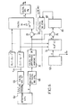
Un calcul doit être effectué pour chaque base bi et pour chaque direction de satellite GPS sj. Pour diminuer la charge de calcul, on peut prendre le même repère de définition des angles de visée pour toutes les bases d'antennes. Le calcul des fonctions de Legendre n'est alors effectué qu'une fois pour chaque satellite. L'évolution des multi-trajets étant à relativement basse fréquence, la connaissance précédente de l'attitude est suffisante pour déterminer les angles de vue, dans un repère lié aux antennes. Il n'y a donc pas d'itération sur la calibration des multi-trajets. On ne calcule plus qu'autant de séries de Legendre qu'il y a de satellites. Ces séries sont obtenues par récurrence puis normalisées par l'intermédiaire d'un tableau précalculé de tous les facteurs à appliquer sur les fonctions. On dispose alors des matrices nécessaires à la résolution de![]()
- Σ est la matrice des sj, en repère inertiel,
- B est la matrice des bases d'antennes, en repère satellite,
- A est la matrice de passage du repère inertiel au repère satellite. L'ensemble des étapes est résumé sur la figure 7.
- Σ is the matrix of s j , in inertial frame,
- B is the matrix of antenna bases, in satellite reference,
- A is the transition matrix from the inertial frame to the satellite frame. The set of steps is summarized in Figure 7.
La matrice A est déterminée par la méthode des moindres carrés. La matrice B est de rang 2, les quatre antennes étant coplanaires. Il en résulte que B.BT est de rang 2. On peut poser :
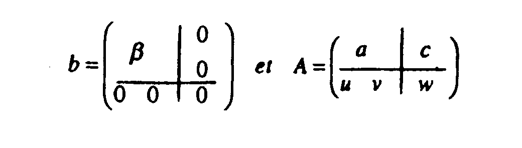
- où β est de
dimension 2par 2, - a est de
dimension 2par 2, - c est de
dimension 2par 1.
- where β is of
dimension 2 by 2, - a is of
dimension 2 by 2, - it is of
dimension 2 by 1.
La résolution par les moindres carrés va fournir a et c. Le triplet de scalaires (u,v,w) est déterminé par trois équations supplémentaires, à savoir :![]()


![]()
La matrice d'attitude est alors le produit de A par la matrice de passage du repère orbital local au repère inertiel notée inv(Rol.In) et les angles θx,θy,θz sont alors déterminés par identification. Les étapes du calcul peuvent être celles résumées en figure 8, avec les notations mathématiques usuelles.The attitude matrix is then the product of A by the transition matrix from the local orbital frame to the inertial frame marked inv (Rol.In) and the angles θx, θy, θz are then determined by identification. The calculation steps can be those summarized in Figure 8, with the usual mathematical notations.
Claims (10)
Applications Claiming Priority (2)
| Application Number | Priority Date | Filing Date | Title |
|---|---|---|---|
| FR9514228 | 1995-12-01 | ||
| FR9514228A FR2741955B1 (en) | 1995-12-01 | 1995-12-01 | SATELLITE ATTITUDE MEASURING METHOD AND DEVICE |
Publications (2)
| Publication Number | Publication Date |
|---|---|
| EP0777128A1 true EP0777128A1 (en) | 1997-06-04 |
| EP0777128B1 EP0777128B1 (en) | 2001-11-07 |
Family
ID=9485059
Family Applications (1)
| Application Number | Title | Priority Date | Filing Date |
|---|---|---|---|
| EP96402579A Expired - Lifetime EP0777128B1 (en) | 1995-12-01 | 1996-11-28 | Method and device for attitude measurement of a satellite |
Country Status (5)
| Country | Link |
|---|---|
| US (1) | US5831572A (en) |
| EP (1) | EP0777128B1 (en) |
| CA (1) | CA2191550A1 (en) |
| DE (1) | DE69616720D1 (en) |
| FR (1) | FR2741955B1 (en) |
Cited By (4)
| Publication number | Priority date | Publication date | Assignee | Title |
|---|---|---|---|---|
| EP0908806A2 (en) * | 1997-09-16 | 1999-04-14 | Space Systems/Loral, Inc. | Global positioning system self calibration attitude determination |
| EP0910001A2 (en) * | 1997-08-12 | 1999-04-21 | Honeywell Inc. | Satellite attitude determination |
| WO2007082929A1 (en) * | 2006-01-19 | 2007-07-26 | Thales | Device for controlling relative postion(s) by analysing dual-frequency signals, for a spacecraft of a group of spacecraft in formation |
| CN104252004A (en) * | 2014-09-11 | 2014-12-31 | 上海卫星工程研究所 | System and method for measuring posture of spin satellite by using single-antenna navigation receiver |
Families Citing this family (13)
| Publication number | Priority date | Publication date | Assignee | Title |
|---|---|---|---|---|
| US6594582B1 (en) * | 1999-05-14 | 2003-07-15 | The United States Of America As Represented By The Administrator Of The National Aeronautics And Space Administration | GPS compound eye attitude and navigation sensor and method |
| US6463366B2 (en) | 2000-03-10 | 2002-10-08 | Schafer Corp | Attitude determination and alignment using electro-optical sensors and global navigation satellites |
| US6760664B1 (en) * | 2001-06-25 | 2004-07-06 | The United States Of America As Represented By The Administrator Of The National Aeronautics And Space Administration | Autonomous navigation system based on GPS and magnetometer data |
| US7124001B2 (en) * | 2003-07-11 | 2006-10-17 | The Boeing Company | Relative attitude estimator for multi-payload attitude determination |
| US7310578B2 (en) * | 2004-01-09 | 2007-12-18 | The Boeing Company | Fast access, low memory, pair catalog |
| US7822572B2 (en) * | 2007-07-06 | 2010-10-26 | Beihang University | Method and device for calibration of digital celestial sensor |
| US8130142B2 (en) | 2009-09-21 | 2012-03-06 | Appareo Systems, Llc | GNSS ultra-short baseline heading determination system and method |
| US9074892B2 (en) | 2013-03-15 | 2015-07-07 | Ian Michael Fink | System and method of determining a position of a remote object |
| US20140267696A1 (en) * | 2013-03-18 | 2014-09-18 | National Applied Research Laboratories (Narl) | Glitch-free data fusion method for combining multiple attitude solutions |
| US9813151B2 (en) * | 2014-08-05 | 2017-11-07 | Massachusetts Institute Of Technology | Free-space optical communication module for small satellites |
| CN105891851B (en) * | 2015-01-23 | 2018-06-08 | 北京空间飞行器总体设计部 | One kind carries out positioning in-orbit verification experimental verification method based on aeronautical satellite leakage signal |
| CN112257026A (en) * | 2020-10-22 | 2021-01-22 | 上海卫星工程研究所 | Spin-stabilized satellite attitude determination method and system based on blind source separation |
| CN112882483B (en) * | 2021-01-12 | 2022-03-04 | 北京控制工程研究所 | Star sensor on-orbit calibration method and device and storage medium |
Citations (2)
| Publication number | Priority date | Publication date | Assignee | Title |
|---|---|---|---|---|
| US4405986A (en) * | 1981-04-17 | 1983-09-20 | The United States Of America As Represented By The Secretary Of The Army | GSP/Doppler sensor velocity derived attitude reference system |
| DE3417661A1 (en) * | 1983-05-13 | 1984-11-15 | Mitsubishi Denki K.K., Tokio/Tokyo | System for controlling the orientation of an artificial satellite |
Family Cites Families (3)
| Publication number | Priority date | Publication date | Assignee | Title |
|---|---|---|---|---|
| US4617634A (en) * | 1983-06-28 | 1986-10-14 | Mitsubishi Denki Kabushiki Kaisha | Artificial satellite attitude control system |
| US5548293A (en) * | 1993-03-24 | 1996-08-20 | Leland Stanford Junior University | System and method for generating attitude determinations using GPS |
| US5561432A (en) * | 1995-05-12 | 1996-10-01 | Trimble Navigation | Out of plane antenna vector system and method |
-
1995
- 1995-12-01 FR FR9514228A patent/FR2741955B1/en not_active Expired - Fee Related
-
1996
- 1996-11-28 EP EP96402579A patent/EP0777128B1/en not_active Expired - Lifetime
- 1996-11-28 DE DE69616720T patent/DE69616720D1/en not_active Expired - Lifetime
- 1996-11-28 CA CA002191550A patent/CA2191550A1/en not_active Abandoned
- 1996-11-29 US US08/758,443 patent/US5831572A/en not_active Expired - Fee Related
Patent Citations (2)
| Publication number | Priority date | Publication date | Assignee | Title |
|---|---|---|---|---|
| US4405986A (en) * | 1981-04-17 | 1983-09-20 | The United States Of America As Represented By The Secretary Of The Army | GSP/Doppler sensor velocity derived attitude reference system |
| DE3417661A1 (en) * | 1983-05-13 | 1984-11-15 | Mitsubishi Denki K.K., Tokio/Tokyo | System for controlling the orientation of an artificial satellite |
Non-Patent Citations (3)
| Title |
|---|
| LUCAS R ET AL: "GLOBAL POSITIONING SYSTEM INTEGRATED NAVIGATION AND ATTITUDE DETERMINATION SYSTEM (GINAS)", SIGNAL PROCESSING THEORIES AND APPLICATIONS, BARCELONA, SEPT. 18 - 21, 1990, vol. 3, 18 September 1990 (1990-09-18), TORRES L;MASGRAU E; LAGUNAS M A, pages 1747 - 1750, XP000365903 * |
| STEIN B A ET AL: "SATELLITE ATTITUDE DETERMINATION USING GPS", 500 YEARS AFTER COLUMBUS - NAVIGATION CHALLENGES OF TOMORROW, MONTEREY, CA., MAR. 23 - 27, 1992, 1 January 1992 (1992-01-01), INSTITUTE OF ELECTRICAL AND ELECTRONICS ENGINEERS, pages 544, XP000344349 * |
| UNWIN ET AL: "RESULTS FROM THE POSAT GPS EXPERIMENT", POSITION LOCATION AND NAVIGATION SYMPOSIUM (PLANS), LAS VEGAS, APR. 11 - 15, 1994, 11 April 1994 (1994-04-11), INSTITUTE OF ELECTRICAL AND ELECTRONICS ENGINEERS, pages 598 - 604, XP000489397 * |
Cited By (9)
| Publication number | Priority date | Publication date | Assignee | Title |
|---|---|---|---|---|
| EP0910001A2 (en) * | 1997-08-12 | 1999-04-21 | Honeywell Inc. | Satellite attitude determination |
| EP0910001A3 (en) * | 1997-08-12 | 2000-08-23 | Honeywell Inc. | Satellite attitude determination |
| EP0908806A2 (en) * | 1997-09-16 | 1999-04-14 | Space Systems/Loral, Inc. | Global positioning system self calibration attitude determination |
| EP0908806A3 (en) * | 1997-09-16 | 2000-09-27 | Space Systems/Loral, Inc. | Global positioning system self calibration attitude determination |
| WO2007082929A1 (en) * | 2006-01-19 | 2007-07-26 | Thales | Device for controlling relative postion(s) by analysing dual-frequency signals, for a spacecraft of a group of spacecraft in formation |
| EP1813957A1 (en) * | 2006-01-19 | 2007-08-01 | Alcatel Lucent | Device controlling relative position(s) by analysing dual frequency signals for use by a spacecraft in a group of spacecraft in formation |
| US8463467B2 (en) | 2006-01-19 | 2013-06-11 | Thales | Device for controlling relative position(s) by analyzing dual-frequency signals, for a spacecraft of a group of spacecraft in formation |
| CN104252004A (en) * | 2014-09-11 | 2014-12-31 | 上海卫星工程研究所 | System and method for measuring posture of spin satellite by using single-antenna navigation receiver |
| CN104252004B (en) * | 2014-09-11 | 2017-01-11 | 上海卫星工程研究所 | System and method for measuring posture of spin satellite by using single-antenna navigation receiver |
Also Published As
| Publication number | Publication date |
|---|---|
| EP0777128B1 (en) | 2001-11-07 |
| US5831572A (en) | 1998-11-03 |
| DE69616720D1 (en) | 2001-12-13 |
| FR2741955A1 (en) | 1997-06-06 |
| CA2191550A1 (en) | 1997-06-02 |
| FR2741955B1 (en) | 1998-02-06 |
Similar Documents
| Publication | Publication Date | Title |
|---|---|---|
| EP0777128B1 (en) | Method and device for attitude measurement of a satellite | |
| EP3623758B1 (en) | Positioning system, and associated method for positioning | |
| EP3658921B1 (en) | Method for calibrating a magnetometer | |
| EP2459966B1 (en) | Method for estimating the direction of a moving solid | |
| EP2718670B1 (en) | Simplified method for estimating the orientation of an object, and attitude sensor implementing such a method | |
| CA2461595A1 (en) | Hybrid inertial navigation system with improved integrity | |
| Socas-Navarro et al. | Characterization of telescope polarization properties across the visible and near-infrared spectrum-Case study: the Dunn Solar Telescope | |
| EP2502202B1 (en) | Method for estimating the movement of a travelling observation instrument flying over a celestial body | |
| BE1023739B1 (en) | AUTONOMOUS AND SELF-CALIBRATED MAGNETIC OBSERVATORY | |
| FR2826447A1 (en) | HYBRID INERTIAL NAVIGATION METHOD AND DEVICE | |
| EP0502771B1 (en) | Procedure and system for autonomous harmonization of equipment on board a vehicle, using means for measuring terrestrial gravitational and magnetic fields | |
| EP2361368A1 (en) | Method for determining a heading in the direction of true north using an inertial measurement unit | |
| EP2694375B1 (en) | Device and method for attitude determination of a satellite, and satellite comprising such a device | |
| EP2500750A1 (en) | Method and device for calibrating a receiver. | |
| EP0209429A1 (en) | Method and device for placing a 3-axis stabilized satellite into a geostationary orbit | |
| EP3385677A1 (en) | A system and a method of analyzing and monitoring interfering movements of an inertial unit during a stage of static alignment | |
| EP0502770A1 (en) | Procedure and system for autonomous harmonization of equipments on bord of a vehicle, using means for measuring terrestrial gravitational field | |
| EP2410293B1 (en) | Method and system for harmonising an angular positioner reference in relation to an Earth-based reference frame | |
| EP0608945B1 (en) | Star sensor with CCD-array, method of detection and application to reposition a spacecraft | |
| EP3374736B1 (en) | Method for designing a navigation path and method for orienting a sighting member from said navigation path | |
| EP3002554B1 (en) | Device and method for positioning a star sensor on the structure of a spacecraft | |
| EP4001851A1 (en) | Method for aligning a plurality of inertial and/or magnetic sensors and device enabling the implementation of such a method | |
| EP3980720A1 (en) | Method and device for resetting an inertial unit of a transport means on the basis of information delivered by a viewfinder of the transport means | |
| WO2024074473A1 (en) | Collaborative navigation method for vehicles having navigation solutions of different accuracies | |
| WO1994019664A1 (en) | Device for the restitution of the orbit of celestial bodies, particularly artificial satellites, by deviatiometry |
Legal Events
| Date | Code | Title | Description |
|---|---|---|---|
| PUAI | Public reference made under article 153(3) epc to a published international application that has entered the european phase |
Free format text: ORIGINAL CODE: 0009012 |
|
| AK | Designated contracting states |
Kind code of ref document: A1 Designated state(s): BE DE ES GB IT SE |
|
| 17P | Request for examination filed |
Effective date: 19970816 |
|
| 17Q | First examination report despatched |
Effective date: 20000331 |
|
| RAP1 | Party data changed (applicant data changed or rights of an application transferred) |
Owner name: ASTRIUM SAS |
|
| GRAG | Despatch of communication of intention to grant |
Free format text: ORIGINAL CODE: EPIDOS AGRA |
|
| GRAG | Despatch of communication of intention to grant |
Free format text: ORIGINAL CODE: EPIDOS AGRA |
|
| GRAH | Despatch of communication of intention to grant a patent |
Free format text: ORIGINAL CODE: EPIDOS IGRA |
|
| GRAH | Despatch of communication of intention to grant a patent |
Free format text: ORIGINAL CODE: EPIDOS IGRA |
|
| GRAA | (expected) grant |
Free format text: ORIGINAL CODE: 0009210 |
|
| AK | Designated contracting states |
Kind code of ref document: B1 Designated state(s): BE DE ES GB IT SE |
|
| PG25 | Lapsed in a contracting state [announced via postgrant information from national office to epo] |
Ref country code: IT Free format text: LAPSE BECAUSE OF FAILURE TO SUBMIT A TRANSLATION OF THE DESCRIPTION OR TO PAY THE FEE WITHIN THE PRE;WARNING: LAPSES OF ITALIAN PATENTS WITH EFFECTIVE DATE BEFORE 2007 MAY HAVE OCCURRED AT ANY TIME BEFORE 2007. THE CORRECT EFFECTIVE DATE MAY BE DIFFERENT FROM THE ONE RECORDED.SCRIBED TIME-LIMIT Effective date: 20011107 Ref country code: GB Free format text: LAPSE BECAUSE OF FAILURE TO SUBMIT A TRANSLATION OF THE DESCRIPTION OR TO PAY THE FEE WITHIN THE PRESCRIBED TIME-LIMIT Effective date: 20011107 |
|
| PG25 | Lapsed in a contracting state [announced via postgrant information from national office to epo] |
Ref country code: BE Free format text: LAPSE BECAUSE OF NON-PAYMENT OF DUE FEES Effective date: 20011130 |
|
| REF | Corresponds to: |
Ref document number: 69616720 Country of ref document: DE Date of ref document: 20011213 |
|
| REG | Reference to a national code |
Ref country code: GB Ref legal event code: IF02 |
|
| PG25 | Lapsed in a contracting state [announced via postgrant information from national office to epo] |
Ref country code: SE Free format text: LAPSE BECAUSE OF FAILURE TO SUBMIT A TRANSLATION OF THE DESCRIPTION OR TO PAY THE FEE WITHIN THE PRESCRIBED TIME-LIMIT Effective date: 20020207 |
|
| PG25 | Lapsed in a contracting state [announced via postgrant information from national office to epo] |
Ref country code: DE Free format text: LAPSE BECAUSE OF FAILURE TO SUBMIT A TRANSLATION OF THE DESCRIPTION OR TO PAY THE FEE WITHIN THE PRESCRIBED TIME-LIMIT Effective date: 20020208 |
|
| GBV | Gb: ep patent (uk) treated as always having been void in accordance with gb section 77(7)/1977 [no translation filed] |
Effective date: 20011107 |
|
| PG25 | Lapsed in a contracting state [announced via postgrant information from national office to epo] |
Ref country code: ES Free format text: LAPSE BECAUSE OF FAILURE TO SUBMIT A TRANSLATION OF THE DESCRIPTION OR TO PAY THE FEE WITHIN THE PRESCRIBED TIME-LIMIT Effective date: 20020530 |
|
| BERE | Be: lapsed |
Owner name: ASTRIUM SAS Effective date: 20011130 |
|
| PLBE | No opposition filed within time limit |
Free format text: ORIGINAL CODE: 0009261 |
|
| STAA | Information on the status of an ep patent application or granted ep patent |
Free format text: STATUS: NO OPPOSITION FILED WITHIN TIME LIMIT |
|
| 26N | No opposition filed |