EP2113403A1 - A bead breaker group for a tire mounting-demounting machine - Google Patents
A bead breaker group for a tire mounting-demounting machine Download PDFInfo
- Publication number
- EP2113403A1 EP2113403A1 EP09158682A EP09158682A EP2113403A1 EP 2113403 A1 EP2113403 A1 EP 2113403A1 EP 09158682 A EP09158682 A EP 09158682A EP 09158682 A EP09158682 A EP 09158682A EP 2113403 A1 EP2113403 A1 EP 2113403A1
- Authority
- EP
- European Patent Office
- Prior art keywords
- bead
- tool
- tire
- rim
- wheel
- Prior art date
- Legal status (The legal status is an assumption and is not a legal conclusion. Google has not performed a legal analysis and makes no representation as to the accuracy of the status listed.)
- Granted
Links
Images


Classifications
-
- B—PERFORMING OPERATIONS; TRANSPORTING
- B60—VEHICLES IN GENERAL
- B60C—VEHICLE TYRES; TYRE INFLATION; TYRE CHANGING; CONNECTING VALVES TO INFLATABLE ELASTIC BODIES IN GENERAL; DEVICES OR ARRANGEMENTS RELATED TO TYRES
- B60C25/00—Apparatus or tools adapted for mounting, removing or inspecting tyres
- B60C25/01—Apparatus or tools adapted for mounting, removing or inspecting tyres for removing tyres from or mounting tyres on wheels
- B60C25/05—Machines
- B60C25/125—Machines for only breaking the beads
- B60C25/13—Machines for only breaking the beads acting axially on a part of the bead or side wall only at localised regions of the bead or side wall
-
- B—PERFORMING OPERATIONS; TRANSPORTING
- B60—VEHICLES IN GENERAL
- B60C—VEHICLE TYRES; TYRE INFLATION; TYRE CHANGING; CONNECTING VALVES TO INFLATABLE ELASTIC BODIES IN GENERAL; DEVICES OR ARRANGEMENTS RELATED TO TYRES
- B60C25/00—Apparatus or tools adapted for mounting, removing or inspecting tyres
- B60C25/01—Apparatus or tools adapted for mounting, removing or inspecting tyres for removing tyres from or mounting tyres on wheels
- B60C25/05—Machines
- B60C25/132—Machines for removing and mounting tyres
- B60C25/135—Machines for removing and mounting tyres having a tyre support or a tool, movable along wheel axis
- B60C25/138—Machines for removing and mounting tyres having a tyre support or a tool, movable along wheel axis with rotary motion of tool or tyre support
-
- Y—GENERAL TAGGING OF NEW TECHNOLOGICAL DEVELOPMENTS; GENERAL TAGGING OF CROSS-SECTIONAL TECHNOLOGIES SPANNING OVER SEVERAL SECTIONS OF THE IPC; TECHNICAL SUBJECTS COVERED BY FORMER USPC CROSS-REFERENCE ART COLLECTIONS [XRACs] AND DIGESTS
- Y10—TECHNICAL SUBJECTS COVERED BY FORMER USPC
- Y10T—TECHNICAL SUBJECTS COVERED BY FORMER US CLASSIFICATION
- Y10T29/00—Metal working
- Y10T29/49—Method of mechanical manufacture
- Y10T29/49481—Wheel making
- Y10T29/49492—Land wheel
- Y10T29/49494—Assembling tire to wheel body
Definitions
- the present invention regards a bead breaker group, as well as a tire mounting-demounting machine provided with such group, along with a new method of bead breaking a tire mounted on a rim.
- the most recently conceived tire mounting-demounting machines comprise a wheel-holder table mounted arranged to rotate on a support base and a column rising from the base, from which one or two telescopic arms extend overhangingly; a bead breaker roller is supported at the free ends of such arms.
- Each bead breaker roller is normally frustoconical, rather flat, is axially and rotatably supported with tilted rotation axis, e. g.
- roller has its distal (end) portion (that which in use is closer to the tire to be bead broken) further away from the column with respect to its own proximal (end) portion (with respect to the column).
- the or each bead breaker roller is brought, typically by means of controlled extension/retraction of the respective telescopic arm which supports it, above the wheel, such that the bead breaker roller is situated at the bead zone of the tire to be bead broken.
- the approaching of the roller to the side of the tire and to the flange of the wheel rim is then operated, until the distal end of the roller abuts against the flank of the tire and against the flange.
- the operator controls e. g.
- feeler pins mounted at each bead breaker roller.
- Each feeler pin is intended to detect, as the approaching is carried out of the respective bead breaker roller to a tire to be bead broken, the position of the roller with respect to the flange of the rim, and upon reaching correct position, sending a signal to a suitable controller which controls the extension-moving back and lowering-return movements of the respective telescopic arm, so as to obtain the penetration of the bead breaker roller between tire and rim in a nearly automatic manner.
- Such feeler pins and the controller nevertheless constitute a rather costly system and involve a considerable increase in the production and maintenance costs of the tire mounting-demounting machines on which they are mounted.
- the main object of the present invention is that of providing a bead breaker group with very simple structure, suitable for being positioned with precision and being easily and quickly inserted between the bead of the tire and the edge of the rim.
- Another object of the present invention is to provide a tire mounting-demounting machine capable of completing the bead breaking operations in a simpler and quicker manner with respect to the conventional tire mounting-demounting.
- Another object of the present invention is that of providing a method for bead breaking that can be achieved without particular difficulties, even by non-expert operators.
- a bead breaker group for bead breaking a tire of a tired wheel equipped with rim with bead-engagement flanges, the bead breaker group comprising a support and at least one bead breaker tool mounted rotatably around a pin borne by the support, the bead breaker tool being substantially flat and comprising:
- a bead breaking method for a tire of a tired wheel comprising the following steps:
- a bead breaker group or head 1 comprising at least one support component, constituted by, for example, a projecting tool-holder arm 2, and a bead breaker tool 3, formed by a substantially flat element, e. g. like a roller mounted rotatably idle at the head of the tool-holder arm 2.
- the tool-holder arm 2 extends, in use, with longitudinal axis perpendicular to the main or rotation axis of a tired wheel to be bead broken.
- the roller plate element 3 has a wide circumferential edge 3a and is sectioned or cut off, in the sense that it is missing a segment section or segment, where it delimits a nearly rectilinear abutment front 3b.
- the tool 3 is rotatably mounted (in any suitable manner) around a fixed pin 4 in turn borne by the tool-carrier arm 2. Consequently, the distance of the circumferential edge 3a from the pin 4 is greater than the distance between the pin 4 and the abutment front 3b.
- the tool-carrier arm 2 can be hollow and bears, preferably at its head, a bracket 5 fixed thereto in any suitable manner, having e. g. an intermediate portion 5a with U-shaped cross section, an attachment shank end 6 ( Fig. 4 ) intended to be inserted in the free end of the tool-carrier arm 2, and the other end 7 bearing the pin 4.
- the pin 4 is preferably made integral with the bracket 5 ( Fig. 4 ), in a single piece, and is oriented along a tilted axis x-x, e. g.
- the tool 3 is mounted on the pin 4 with the interposition of antifriction means, typically one or more bearings 8.
- the tool-holder arm 2 is installable on a tire mounting-demounting machine equipped with rotatable wheel-holder table and support upright or column, as will be further described below, and can be a telescopic arm or an arm with several articulated sections, in any case with the possibility of being moved in a plane substantially orthogonal to the rotation axis of the wheel-holder table.
- the tool-holder arm 2 has a transversely-jutting ear-shaped element 9, to which a control handle or the like for manually moving or maneuvering the bead breaker group can be fixed.
- the operator after having locked a tired wheel to be bead broken on the rotatable wheel-holder table of a tire mounting-demounting machine, moves the arm 2 in a manner such that the bead breaker tool 3 is immediately above or in any case close to the flank of the tire of the wheel and close to the respective flange of the rim.
- the bead breaker tool 3 with its own abutment front 3b is brought against the flange of the rim and is maintained in such abutted or slightly forced position against the adjacent flank of the tire.
- a bead breaker group 1 a is illustrated that is entirely similar to that described with reference to Figs. 1 - 4 , but is provided with an actuator means, for example a double-effect pneumatic jack 10, whose cylinder 10a is articulated to the tool-holder arm 2, preferably by means of a fork bracket 11, while its stem 10b is articulated to the bead breaker tool 3 in a predetermined position at the zone subtended by the edge 3a.
- an actuator means for example a double-effect pneumatic jack 10, whose cylinder 10a is articulated to the tool-holder arm 2, preferably by means of a fork bracket 11, while its stem 10b is articulated to the bead breaker tool 3 in a predetermined position at the zone subtended by the edge 3a.
- a bead breaker group 1b is instead illustrated equipped with an elastic return means, for example a helical spring 12, for the tool 3, which on one side is fixed to a pin 13, in turn fixed to the bracket 5, and on the other side (for example by means of a pin 14) is fixed to the bead breaker tool 3, such that the rotation of the tool 3 with respect to the support component is opposed by the action of the spring 12.
- an elastic return means for example a helical spring 12
- the wheel-holder table After having brought, as described above, the tool 3 with its own engagement front 3b in abutment against the flange of the rim and against the flank of the tire, the wheel-holder table is rotated in clockwise direction, thus causing the rotation and penetration of the tool, opposing the action of the spring 12.
- the spring 12 Upon completed bead breaking, by operating the stopping of the wheel-holder table, the spring 12 will bring the tool 3 into rest position, i.e. in a position of disengagement both from the bead of the tire and from the rim. It will then be possible to move the bead breaker group away from the now-bead broken tired wheel.
- a bead breaker group 1c is instead illustrated, which is similar to that illustrated in Figs. 5 to 8 , but has an antifriction element, such as a counter-roller element 15 mounted idle and coaxial with the tool 3 at the face of the latter that in use is turned against the flank of the tire to be bead broken.
- an antifriction element such as a counter-roller element 15 mounted idle and coaxial with the tool 3 at the face of the latter that in use is turned against the flank of the tire to be bead broken.
- the tool 3 has a slightly different configuration from that of the tools according to the above-described embodiments, and in particular is configured as an oscillating arm and has an engagement-penetration zone, shaped as a tip 3c, and two lateral abutment fronts, configured as a rectilinear segment 3d, arranged with one on one side of the engagement zone 3c and the other on the other side of such zone 3c.
- the distance between engagement front 3d and pin 4 is less than the distance between pin 4 and engagement-penetration zone 3c.
- a bead breaker group 1d is illustrated very similar to that described above, except that the tool has an engagement-penetration zone 3e of greater extension than the zone 3c, and two substantially parallel abutment fronts 3f. Also for such group, the distance between abutment front 3f and pin 4 is less than the distance between pin 4 and engagement-penetration zone 3d.
- Figs. 23 to 28 illustrate a bead breaker group 1 e like that illustrated in Figs. 17 - 22 , but a helical spring 12 is provided in place of the actuator 10.
- a tire mounting-demounting machine having a support base B for a wheel-holder table, from which a column C upwardly extends.
- Such machine also provides for additional (two in the illustrated example) tool-holder arms, at least one of which supports a bead breaker group like that which is the subject of the present invention.
- a tire mounting-demounting machine can also be equipped with additional bead breaking groups according to the present invention, e. g. a pair intended for simultaneously bead breaking a respective flank (in use, an upper and a lower) of a tire.
- a bead breaker group was described for machines with wheel-holder table with vertical rotation axis, but the same considerations can be made for machines with wheel-holder table with rotation axis that is horizontal or tilted with respect to the vertical.
Landscapes
- Engineering & Computer Science (AREA)
- Mechanical Engineering (AREA)
- Tires In General (AREA)
- Automatic Tape Cassette Changers (AREA)
- Automatic Tool Replacement In Machine Tools (AREA)
Abstract
- at least one portion configured as an abutment front (3b,3d,3f) against a flange of a rim of a tired wheel to be bead broken; and
- at least one portion having curved peripheral edge substantially coaxial with the pin (4) and intended to act as an engagement-penetration zone (3a,3c,3e) between the flange of a rim and the bead of a tire to be bead broken,
the distance between the abutment front (3b,3d,3f) and the pin (4) being less than the distance between the pin (4) and the at least one engagement-penetration zone (3a,3c,3e).
Description
- The present invention regards a bead breaker group, as well as a tire mounting-demounting machine provided with such group, along with a new method of bead breaking a tire mounted on a rim.
- As is known, in order demount a tire from a rim, it is first necessary to break the bead of the tire, i.e. separate its beads from the respective edge of the rim and then force, by means of a suitable tire mounting-demounting tool, at least one bead of the tire to go beyond the edge of the rim facing thereto. The bead breaking operation is achieved by means of a so-called bead breaker tool, which can be of fixed type or it can be configured as an idle roller.
- The most recently conceived tire mounting-demounting machines comprise a wheel-holder table mounted arranged to rotate on a support base and a column rising from the base, from which one or two telescopic arms extend overhangingly; a bead breaker roller is supported at the free ends of such arms. Each bead breaker roller is normally frustoconical, rather flat, is axially and rotatably supported with tilted rotation axis, e. g. 45°, and contained in a plane passing through the longitudinal axis of the its respective telescopic arm, so that the roller has its distal (end) portion (that which in use is closer to the tire to be bead broken) further away from the column with respect to its own proximal (end) portion (with respect to the column).
- In order to carry out a bead breaking operation, after having fixed a tired wheel on the wheel-holder table of the tire mounting-demounting machine, the or each bead breaker roller is brought, typically by means of controlled extension/retraction of the respective telescopic arm which supports it, above the wheel, such that the bead breaker roller is situated at the bead zone of the tire to be bead broken. The approaching of the roller to the side of the tire and to the flange of the wheel rim is then operated, until the distal end of the roller abuts against the flank of the tire and against the flange. At this point, the operator controls (e. g. by means of extension of the telescopic roller-holder arm) a movement of the bead breaker roller in a substantially radial direction (with respect to the rim) and its distal end is then forced to penetrate between the edge of the rim and the bead of the tire. Finally, the wheel-holder table is rotated in order to complete the bead breaking operation over the entire length of the tire bead.
- With the bead breaker rollers proposed up to now, a constant intervention of the operator is therefore necessary, as such operator must first drive the advancing of the roller towards the axis of the wheel-holder table and then drive an advancing-lowering of the roller itself between the bead of the tire and the flange of the rim. Following an imprecise driving of the roller by the operator, it can occur that the tire or the rim is ruined, or that the advancing and advancing-lowering operations of the roller must be repeated several times before correctly completing the bead breaking.
- In order to remedy this drawback, it was proposed to use so-called feeler pins mounted at each bead breaker roller. Each feeler pin is intended to detect, as the approaching is carried out of the respective bead breaker roller to a tire to be bead broken, the position of the roller with respect to the flange of the rim, and upon reaching correct position, sending a signal to a suitable controller which controls the extension-moving back and lowering-return movements of the respective telescopic arm, so as to obtain the penetration of the bead breaker roller between tire and rim in a nearly automatic manner. Such feeler pins and the controller nevertheless constitute a rather costly system and involve a considerable increase in the production and maintenance costs of the tire mounting-demounting machines on which they are mounted.
- Therefore, the main object of the present invention is that of providing a bead breaker group with very simple structure, suitable for being positioned with precision and being easily and quickly inserted between the bead of the tire and the edge of the rim.
- Another object of the present invention is to provide a tire mounting-demounting machine capable of completing the bead breaking operations in a simpler and quicker manner with respect to the conventional tire mounting-demounting.
- Another object of the present invention is that of providing a method for bead breaking that can be achieved without particular difficulties, even by non-expert operators.
- According to a first aspect of the present invention, a bead breaker group is provided for bead breaking a tire of a tired wheel equipped with rim with bead-engagement flanges, the bead breaker group comprising a support and at least one bead breaker tool mounted rotatably around a pin borne by the support, the bead breaker tool being substantially flat and comprising:
- at least one portion configured as an abutment front against a flange of a rim of a tired wheel to be bead broken; and
- at least one portion having curved peripheral edge substantially coaxial with the pin and intended to act as an engagement-penetration zone between the flange of a rim and the bead of a tire to be bead broken,
- According to another aspect of the present invention, a bead breaking method is provided for a tire of a tired wheel comprising the following steps:
- a) prearranging, on a wheel-holder table, a tired wheel having a rim and a tire;
- b) moving a bead breaker group so as to move the at least one portion configured as an abutment front in abutment against a flange of a rim of the tired wheel to be bead broken;
- c) rotating the wheel-holder table, in such a manner also causing the rotation via driving of the tool, with consequent engagement-penetration of the engagement-penetration zone between the flange of the rim and the bead of the tire.
- Further aspects of the present invention will be clearer from the following detailed description of several specific embodiments of a bead breaker group, description made with reference to the accompanying drawings, in which:
-
Figures 1 and 2 are perspective, slightly top views of a first bead breaker group embodiment according to the present invention, in two different work positions; -
Figure 3 is a top view ofFig. 1 ; -
Figure 4 is a section view taken along the line IV-IV ofFig. 3 ; -
Figures 5 to 8 are similar views, respectively, ofFigs. 1 to 4 , but which illustrate a second bead breaker group embodiment according to the present invention; -
Figures 9 to 12 are similar views, respectively, ofFigs. 1 - 4 , but which illustrate a third bead breaker group embodiment according to the present invention; -
Figures 13 to 16 are similar views, respectively, ofFigs. 1 - 4 , but which illustrate a fourth bead breaker group embodiment according to the present invention; -
Figures 17 to 20 are similar views, respectively, ofFigs. 1 - 4 , but which illustrate a fifth bead breaker group embodiment according to the present invention; -
Figures 21 and 22 are perspective, slightly top views of a bead breaker group according toFigs. 17 - 20 , in two different work positions; -
Figures 23 to 26 are similar views, respectively, ofFigs. 1 - 4 , but which illustrate a sixth bead breaker group embodiment according to the present invention; -
Figures 27 to 28 are perspective, slightly top views of a bead breaker group according toFigs. 23 - 26 in two different work positions; and -
Figures 29 and 30 are perspective, slightly top views of a tire mounting-demounting machine according to the present invention, equipped with a bead breaker group and in two different work positions. - In the drawing set, equivalent or similar parts or components were marked with the same reference numbers.
- First, with reference to
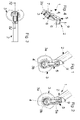
Figs. 1 - 4 , a bead breaker group orhead 1 is illustrated comprising at least one support component, constituted by, for example, a projecting tool-holder arm 2, and abead breaker tool 3, formed by a substantially flat element, e. g. like a roller mounted rotatably idle at the head of the tool-holder arm 2. The tool-holder arm 2 extends, in use, with longitudinal axis perpendicular to the main or rotation axis of a tired wheel to be bead broken. - The
roller plate element 3 has a widecircumferential edge 3a and is sectioned or cut off, in the sense that it is missing a segment section or segment, where it delimits a nearlyrectilinear abutment front 3b. Thetool 3 is rotatably mounted (in any suitable manner) around a fixedpin 4 in turn borne by the tool-carrier arm 2. Consequently, the distance of thecircumferential edge 3a from thepin 4 is greater than the distance between thepin 4 and theabutment front 3b. - Structurally, the tool-
carrier arm 2 can be hollow and bears, preferably at its head, abracket 5 fixed thereto in any suitable manner, having e. g. anintermediate portion 5a with U-shaped cross section, an attachment shank end 6 (Fig. 4 ) intended to be inserted in the free end of the tool-carrier arm 2, and theother end 7 bearing thepin 4. Thepin 4 is preferably made integral with the bracket 5 (Fig. 4 ), in a single piece, and is oriented along a tilted axis x-x, e. g. tilted 45° with respect to the longitudinal axis of the tool-holder arm 2 and thus tilted during use, also with respect to the main axis of a tired wheel to be bead broken. In such case, thetool 3 is mounted on thepin 4 with the interposition of antifriction means, typically one or more bearings 8. - The tool-
holder arm 2 is installable on a tire mounting-demounting machine equipped with rotatable wheel-holder table and support upright or column, as will be further described below, and can be a telescopic arm or an arm with several articulated sections, in any case with the possibility of being moved in a plane substantially orthogonal to the rotation axis of the wheel-holder table. - If desired, the tool-
holder arm 2 has a transversely-jutting ear-shaped element 9, to which a control handle or the like for manually moving or maneuvering the bead breaker group can be fixed. - The operation of one such bead breaker group is quite simple.
- The operator, after having locked a tired wheel to be bead broken on the rotatable wheel-holder table of a tire mounting-demounting machine, moves the
arm 2 in a manner such that thebead breaker tool 3 is immediately above or in any case close to the flank of the tire of the wheel and close to the respective flange of the rim. At this point, thebead breaker tool 3 with itsown abutment front 3b is brought against the flange of the rim and is maintained in such abutted or slightly forced position against the adjacent flank of the tire. - The operator then controls the rotation of the wheel-holder table and due to the friction between tire and
bead breaker tool 3, the latter will be rotated together with the tire, so that itscircumferential portion 3a will be forced to be engaged and to penetrate between the flange of the rim and the bead of the tire, i.e. it will carry out an angular penetration travel, thus initiating the bead breaking of the wheel. Upon completed bead breaking, it will be sufficient to make the wheel-carrier table briefly rotate in the direction opposite its previous rotation direction, in order to force the tool to disengage by means of an angular backward travel. - With reference to
Figs. 5 - 8 , abead breaker group 1 a is illustrated that is entirely similar to that described with reference toFigs. 1 - 4 , but is provided with an actuator means, for example a double-effectpneumatic jack 10, whosecylinder 10a is articulated to the tool-holder arm 2, preferably by means of afork bracket 11, while itsstem 10b is articulated to thebead breaker tool 3 in a predetermined position at the zone subtended by theedge 3a. - For the functioning of one such bead breaker group, one proceeds as in the previously described example, except that after having brought the tool 3 (initially with
stem 10b of thejack 10 retracted) with itsown abutment front 3b in abutment against the flange of the rim, the extension of thestem 10b is operated, followed by the forced rotation of thetool 2, which will be obliged to penetrate between the tire and the rim, initiating the bead breaking. The tired wheel is then rotated, and upon completion of the bead breaking operation, thestem 10b is operated to move back, so that thetool 3 is disengaged both from the rim and from the bead of the tire, after which the bead breaker group can be moved away from the bead broken wheel. - In
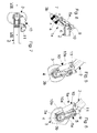
Figs. 9 to 12 , abead breaker group 1b is instead illustrated equipped with an elastic return means, for example ahelical spring 12, for thetool 3, which on one side is fixed to apin 13, in turn fixed to thebracket 5, and on the other side (for example by means of a pin 14) is fixed to thebead breaker tool 3, such that the rotation of thetool 3 with respect to the support component is opposed by the action of thespring 12. - After having brought, as described above, the
tool 3 with itsown engagement front 3b in abutment against the flange of the rim and against the flank of the tire, the wheel-holder table is rotated in clockwise direction, thus causing the rotation and penetration of the tool, opposing the action of thespring 12. Upon completed bead breaking, by operating the stopping of the wheel-holder table, thespring 12 will bring thetool 3 into rest position, i.e. in a position of disengagement both from the bead of the tire and from the rim. It will then be possible to move the bead breaker group away from the now-bead broken tired wheel. - With reference to
Figs. 13 to 16 , abead breaker group 1c is instead illustrated, which is similar to that illustrated inFigs. 5 to 8 , but has an antifriction element, such as acounter-roller element 15 mounted idle and coaxial with thetool 3 at the face of the latter that in use is turned against the flank of the tire to be bead broken. - Moreover, the
tool 3 has a slightly different configuration from that of the tools according to the above-described embodiments, and in particular is configured as an oscillating arm and has an engagement-penetration zone, shaped as atip 3c, and two lateral abutment fronts, configured as arectilinear segment 3d, arranged with one on one side of theengagement zone 3c and the other on the other side ofsuch zone 3c. - Also for such group, the distance between
engagement front 3d andpin 4 is less than the distance betweenpin 4 and engagement-penetration zone 3c. - Such tool functions substantially in the same manner described with reference in
Figs. 5 to 8 , nevertheless, during the bead breaking operations, thecounter-roller element 15 is driven in rotation by the tire and reduces the friction between tire and tool. - In the absence of
such counter-roller element 15, the operator before demounting a tired wheel would be obliged to spread grease over part of the tire, in order to facilitate the sliding of the tools (mounting or bead breaking) on the tire during the various work operations. - In
Figs. 17 to 22 , abead breaker group 1d is illustrated very similar to that described above, except that the tool has an engagement-penetration zone 3e of greater extension than thezone 3c, and two substantiallyparallel abutment fronts 3f. Also for such group, the distance betweenabutment front 3f andpin 4 is less than the distance betweenpin 4 and engagement-penetration zone 3d. -
Figs. 23 to 28 , on the other hand, illustrate abead breaker group 1 e like that illustrated inFigs. 17 - 22 , but ahelical spring 12 is provided in place of theactuator 10. - Finally, with reference to
Figs. 29 and 30 , a tire mounting-demounting machine is illustrated having a support base B for a wheel-holder table, from which a column C upwardly extends. Such machine also provides for additional (two in the illustrated example) tool-holder arms, at least one of which supports a bead breaker group like that which is the subject of the present invention. - It will be understood that with a bead breaker group according to the present invention it is possible to carry out bead breaking operations in a much simpler and quicker manner with respect to the groups proposed up to now. Indeed, the operator, after having mounted a tired wheel on the table, brings the group just above the tire (for the machines with vertical column and wheel-holder with vertical rotation axis), then brings the group close to the tire until the tool, at its abutment front zone, is abutting against the flank of the tire, the engagement-penetration zone(s) being instead raised with respect to the flank itself. By rotating the table or by driving the actuator, rotation is caused (see in particular
Figs. 22 and28 ) of the tool which is inserted below the edge of the rim, and thus penetrates between the tire and the rim. - Therefore, unlike the bead breaker groups proposed up to now, one will appreciate the fact that the operator does not have to control the tool to be moved in a combined manner in the direction of the table axis and towards the axis itself, but he must only control the tool to be moved parallel to the axis of the table, and the configuration of the tool will allow the penetration (automatic if the actuator is not provided) of the tool itself between the tire and rim.
- A man skilled in the art will understand that a tire mounting-demounting machine can also be equipped with additional bead breaking groups according to the present invention, e. g. a pair intended for simultaneously bead breaking a respective flank (in use, an upper and a lower) of a tire.
- A bead breaker group was described for machines with wheel-holder table with vertical rotation axis, but the same considerations can be made for machines with wheel-holder table with rotation axis that is horizontal or tilted with respect to the vertical.
- The bead breaker group described above is susceptible to numerous modifications and variations within the protection scope defined by the following claims.
Claims (16)
- A bead breaker group for bead breaking a tire of a tired wheel equipped with rim with bead-engagement flanges, said bead breaker group comprising a support (2, 5) and at least one bead breaker tool (3) mounted for rotation around a pin (4) borne by said support (2, 5), and characterized in that said bead breaker tool is substantially flat and comprises:- at least one portion configured as an abutment front (3b, 3d, 3f) against a flange of a rim of a tired wheel to be bead broken; and- at least one portion having curved peripheral edge substantially coaxial with the pin (4) and intended to act as an engagement-penetration zone (3a, 3c, 3e) between the flange of a rim and the bead of a tire to be bead broken,the distance between said abutment front (3b, 3d, 3f) and said pin (4) being less than the distance between said pin (4) and said at least one engagement-penetration zone (3a, 3c, 3e).
- A group according to claim 1, characterized in that it comprises at least one actuator means (10) intended to control angular movements of said tool around said pin (4) and secured on one side to said support (2, 5) and on the other side to said bead breaker tool (3).
- A group according to claim 2, characterized in that said actuator means (10) is secured to said bead breaker tool (3) at said engagement-penetration zone (3a, 3c, 3e).
- A group according to any claim 1 to 3, characterized in that said bead breaker tool (2) comprises at least one return means (12) which opposes angular engagement-penetration movements of said tool (3) around said pin (4).
- A group according to any preceding claim, characterized in that said bead breaker tool (2) comprises at least one antifriction element (15) intended to dampen, in use, friction between the tool and the tire.
- A group according to claim 5, characterized in that said at least one antifriction element comprises a counter-roller (15) mounted idle on said pin (4) at the face of said bead breaker tool (3) directed, in use, against a tire.
- A group according to any preceding claim, characterized in that said bead breaker tool (3) is configured as a sectioned roller lacking a segment thereof, thereby having a rectilinear front (3b).
- A group according to any preceding claim, characterized in that said bead breaker tool (3) is configured as an oscillating arm, and has an engagement-penetration edge (3c, 3e) and two lateral abutment fronts (3d, 3f).
- A group according to claim 8, characterized in that said two lateral abutment fronts (3f) are substantially parallel to each other.
- A group according to any preceding claim, characterized in that said support comprises a projecting tool-holder arm (2) terminating with a bracket element (5) set for supporting said pin (4) with longitudinal axis tilted with respect to said tool-holder arm (2).
- A tire mounting-demounting machine comprising a base (B), a wheel-holder table rotatably supported by said base and a column (C) extending upward starting from said base (B), characterized in that it comprises at least one bead breaker group according any claim 1 and 3 to 10 supported by said column (C).
- A method for bead breaking a tire of a tired wheel by means of a tire mounting-demounting machine according to claim 11, characterized in that it comprises the following steps:a) prearranging, on said wheel-holder table, a tired wheel having a rim and a tire;b) moving a bead breaker group so as to move said at least one portion configured as an abutment front (3b, 3d, 3f) in abutment against a flange of a rim of the tired wheel to be bead broken;c) rotating said wheel-holder table, thus also causing the rotation via driving of said tool with consequent engagement-penetration of said engagement-penetration zone (3a, 3c, 3e) between the flange of the rim and the bead of the tire.
- A method according to claim 12, characterized in that it comprises the stopping and reversing of the rotation direction of said wheel-holder table upon completed bead breaking, in order to disengage said tool from the rim and from the tire by forcing it to carry out, due to friction, an angular travel in the direction opposite that carried out during said step c).
- A tire mounting-demounting machine comprising a base (B), a wheel-holder table rotatably supported by said base and a column (C) extended upward starting from said base (B), characterized in that it comprises at least one bead breaker group according to claim 2 supported by said column (C).
- A method for bead breaking a tire with a tire mounting-demounting machine according to claim 14, characterized in that it comprises the following steps:a) prearranging a tired wheel including a tire and a rim on said wheel-holder table;b) moving a bead breaker group so as to move said at least one portion configured as an abutment front (3b, 3d, 3f) in abutment against a flange of a rim of the tired wheel to be bead broken;c) driving said at least one actuator means for operating an angular engagement-insertion movement of said tool between said flange of the rim and the bead of the tire; andd) rotating said wheel-holder table.
- A method according to claim 15, characterized in that it comprises stopping said wheel-holder table and backward-driving said actuator means in order to disengage said tool from the rim and from the tire.
Applications Claiming Priority (1)
| Application Number | Priority Date | Filing Date | Title |
|---|---|---|---|
| IT000050A ITVR20080050A1 (en) | 2008-04-28 | 2008-04-28 | BREAKER GROUP FOR A TIRE CHANGER MACHINE |
Publications (2)
| Publication Number | Publication Date |
|---|---|
| EP2113403A1 true EP2113403A1 (en) | 2009-11-04 |
| EP2113403B1 EP2113403B1 (en) | 2013-03-27 |
Family
ID=40297439
Family Applications (1)
| Application Number | Title | Priority Date | Filing Date |
|---|---|---|---|
| EP09158682A Active EP2113403B1 (en) | 2008-04-28 | 2009-04-24 | A bead breaker group for a tire mounting-demounting machine |
Country Status (6)
| Country | Link |
|---|---|
| US (1) | US8464774B2 (en) |
| EP (1) | EP2113403B1 (en) |
| JP (1) | JP5404162B2 (en) |
| CN (1) | CN101570118B (en) |
| ES (1) | ES2410262T3 (en) |
| IT (1) | ITVR20080050A1 (en) |
Cited By (3)
| Publication number | Priority date | Publication date | Assignee | Title |
|---|---|---|---|---|
| ITMO20120206A1 (en) * | 2012-09-04 | 2014-03-05 | M & B Engineering S R L | TANK MACHINE |
| IT201700028239A1 (en) * | 2017-03-14 | 2018-09-14 | Nexion Spa | TOOL FOR TIRE CHANGER MACHINE |
| US11254174B2 (en) | 2018-10-10 | 2022-02-22 | Butler Engineering And Marketing S.P.A. | Machine for mounting and/or removing vehicle wheels, in particular truck wheels |
Families Citing this family (6)
| Publication number | Priority date | Publication date | Assignee | Title |
|---|---|---|---|---|
| US8985178B1 (en) | 2010-04-23 | 2015-03-24 | Hunter Engineering Company | Tire bead breaker device and methods for automated tire changer machine |
| JP6357446B2 (en) * | 2015-05-26 | 2018-07-11 | 小野谷機工株式会社 | Tire attachment / detachment method |
| IT201600111370A1 (en) * | 2016-11-04 | 2018-05-04 | Nexion Spa | APPARATUS FOR MOUNTING AND DISASSEMBLING A TIRE |
| CN108569089A (en) * | 2017-03-09 | 2018-09-25 | 科维(营口)工业有限公司 | A kind of tyre-pressing disc positioning device and tire changer |
| CN110126557B (en) * | 2019-05-23 | 2025-01-14 | 营口大力汽保设备科技有限公司 | A disassembly and assembly lower operating head device for a disassembly and assembly machine |
| CN114801604B (en) * | 2022-04-15 | 2023-08-01 | 伺轮智能机器人(南京)有限公司 | Method and device for detecting separation state of tire and rim |
Citations (2)
| Publication number | Priority date | Publication date | Assignee | Title |
|---|---|---|---|---|
| EP1314584A1 (en) | 2001-11-22 | 2003-05-28 | BUTLER ENGINEERING & MARKETING S.r.l. | Bead releasing and removing head for a tire-fitting machine |
| EP1714807A1 (en) | 2005-03-23 | 2006-10-25 | BUTLER ENGINEERING & MARKETING SPA | Tool for automatically assembling or disassembling a tyre to/from a wheel rim |
Family Cites Families (11)
| Publication number | Priority date | Publication date | Assignee | Title |
|---|---|---|---|---|
| US3032095A (en) * | 1959-01-30 | 1962-05-01 | Big Four Ind Inc | Tire demounting apparatus |
| CH573319A5 (en) * | 1972-06-16 | 1976-03-15 | Duquesne Victor | |
| JPS5174303A (en) * | 1974-12-23 | 1976-06-28 | Yamada Yuki Seizo Co Ltd | TAIYA HAZUSHIKI |
| FR2391864A1 (en) * | 1976-10-06 | 1978-12-22 | Michelin & Cie | TIRE ASSEMBLY / DISASSEMBLY MACHINE |
| USRE33892E (en) * | 1987-04-15 | 1992-04-21 | Freezone Pty Ltd | Tire bead breaker |
| US4939941A (en) * | 1988-09-09 | 1990-07-10 | Coats Wheel Balancer Corp. | Combined distance and diameter measuring apparatus for wheel balancing machine |
| ITVR20020060A1 (en) * | 2002-05-29 | 2003-12-01 | Butler Eng & Marketing | TIRE CHANGER ASSEMBLING MACHINE |
| ITRE20020068A1 (en) * | 2002-09-13 | 2004-03-14 | Corghi Spa | AUTOMATIC SIMPLIFIED DEVICE FOR DISASSEMBLY |
| US7355687B2 (en) * | 2003-02-20 | 2008-04-08 | Hunter Engineering Company | Method and apparatus for vehicle service system with imaging components |
| ITVR20040055A1 (en) * | 2004-04-09 | 2004-07-09 | Butler Eng & Marketing | AUTOMATIC FEELER FOR TIRE MOUNTING MACHINES |
| ITMO20040205A1 (en) * | 2004-08-03 | 2004-11-03 | Sicam Srl | 'MACHINE PERFECTED FOR THE MOTORCYCLE AND DISASSEMBLY OF TIRES OF VEHICLE WHEELS'. |
-
2008
- 2008-04-28 IT IT000050A patent/ITVR20080050A1/en unknown
-
2009
- 2009-04-07 US US12/419,743 patent/US8464774B2/en active Active
- 2009-04-24 EP EP09158682A patent/EP2113403B1/en active Active
- 2009-04-24 ES ES09158682T patent/ES2410262T3/en active Active
- 2009-04-27 JP JP2009108450A patent/JP5404162B2/en not_active Expired - Fee Related
- 2009-04-28 CN CN2009101369489A patent/CN101570118B/en not_active Expired - Fee Related
Patent Citations (2)
| Publication number | Priority date | Publication date | Assignee | Title |
|---|---|---|---|---|
| EP1314584A1 (en) | 2001-11-22 | 2003-05-28 | BUTLER ENGINEERING & MARKETING S.r.l. | Bead releasing and removing head for a tire-fitting machine |
| EP1714807A1 (en) | 2005-03-23 | 2006-10-25 | BUTLER ENGINEERING & MARKETING SPA | Tool for automatically assembling or disassembling a tyre to/from a wheel rim |
Cited By (4)
| Publication number | Priority date | Publication date | Assignee | Title |
|---|---|---|---|---|
| ITMO20120206A1 (en) * | 2012-09-04 | 2014-03-05 | M & B Engineering S R L | TANK MACHINE |
| WO2014037771A1 (en) * | 2012-09-04 | 2014-03-13 | M&B Engineering S.R.L. | Tyre-changing machine |
| IT201700028239A1 (en) * | 2017-03-14 | 2018-09-14 | Nexion Spa | TOOL FOR TIRE CHANGER MACHINE |
| US11254174B2 (en) | 2018-10-10 | 2022-02-22 | Butler Engineering And Marketing S.P.A. | Machine for mounting and/or removing vehicle wheels, in particular truck wheels |
Also Published As
| Publication number | Publication date |
|---|---|
| US20090266493A1 (en) | 2009-10-29 |
| CN101570118A (en) | 2009-11-04 |
| JP5404162B2 (en) | 2014-01-29 |
| ES2410262T3 (en) | 2013-07-01 |
| JP2009262929A (en) | 2009-11-12 |
| EP2113403B1 (en) | 2013-03-27 |
| US8464774B2 (en) | 2013-06-18 |
| ITVR20080050A1 (en) | 2009-10-29 |
| CN101570118B (en) | 2013-03-06 |
Similar Documents
| Publication | Publication Date | Title |
|---|---|---|
| EP2113403B1 (en) | A bead breaker group for a tire mounting-demounting machine | |
| EP2463125B1 (en) | A device for demounting a tire from a rim as well as a tire demounting machine equipped with such device. | |
| US8905112B2 (en) | Device for demounting the second bead of a tire from a rim and respective demounting method | |
| US6422285B1 (en) | Tire changing machine for industrial vehicle wheels | |
| EP2042351B1 (en) | A bead breaker roller head for a tire mounting-demounting machine | |
| EP1334846B1 (en) | Bead releasing and tire disassembling group in a tire assembling-disassembling machine | |
| US8973640B1 (en) | Demount tool assembly and methods for automated tire changer machine | |
| US7497761B2 (en) | Tool for automatically assembling-disassembling a tire to/from a wheel rim | |
| EP2962876A1 (en) | Machine and method for fitting and removing a tyre | |
| US20160001618A1 (en) | Machine and method for fitting and removing a tyre | |
| US10189322B2 (en) | Device for disassembling a tire from a wheel rim and a method of disassembling a tired wheel | |
| WO2012052970A1 (en) | A tyre demounting machine | |
| EP2524819B1 (en) | Bead breaking unit for tyre changing machines | |
| EP2995478B1 (en) | Machine for removing and fitting wheel tyres for vehicles | |
| US7946016B2 (en) | Method and machine for removing a tyre fitted with a rigid inner run-flat ring | |
| EP2253488B1 (en) | A bead breaker group for a tire mounting-demounting machine | |
| EP2756969A1 (en) | Machine for removing/ fitting a tyre from/ on the rim of a vehicle vehicles | |
| EP4532231B1 (en) | Device for fitting/removing tires | |
| US20240246376A1 (en) | Device for fitting/removing tires |
Legal Events
| Date | Code | Title | Description |
|---|---|---|---|
| PUAI | Public reference made under article 153(3) epc to a published international application that has entered the european phase |
Free format text: ORIGINAL CODE: 0009012 |
|
| AK | Designated contracting states |
Kind code of ref document: A1 Designated state(s): AT BE BG CH CY CZ DE DK EE ES FI FR GB GR HR HU IE IS IT LI LT LU LV MC MK MT NL NO PL PT RO SE SI SK TR |
|
| 17P | Request for examination filed |
Effective date: 20100503 |
|
| 17Q | First examination report despatched |
Effective date: 20120810 |
|
| REG | Reference to a national code |
Ref country code: DE Ref legal event code: R079 Ref document number: 602009014327 Country of ref document: DE Free format text: PREVIOUS MAIN CLASS: B60C0025130000 Ipc: B60C0025138000 |
|
| RIC1 | Information provided on ipc code assigned before grant |
Ipc: B60C 25/138 20060101AFI20120927BHEP Ipc: B60C 25/13 20060101ALI20120927BHEP |
|
| GRAP | Despatch of communication of intention to grant a patent |
Free format text: ORIGINAL CODE: EPIDOSNIGR1 |
|
| GRAS | Grant fee paid |
Free format text: ORIGINAL CODE: EPIDOSNIGR3 |
|
| GRAP | Despatch of communication of intention to grant a patent |
Free format text: ORIGINAL CODE: EPIDOSNIGR1 |
|
| GRAA | (expected) grant |
Free format text: ORIGINAL CODE: 0009210 |
|
| AK | Designated contracting states |
Kind code of ref document: B1 Designated state(s): AT BE BG CH CY CZ DE DK EE ES FI FR GB GR HR HU IE IS IT LI LT LU LV MC MK MT NL NO PL PT RO SE SI SK TR |
|
| REG | Reference to a national code |
Ref country code: GB Ref legal event code: FG4D |
|
| REG | Reference to a national code |
Ref country code: CH Ref legal event code: EP |
|
| REG | Reference to a national code |
Ref country code: AT Ref legal event code: REF Ref document number: 603133 Country of ref document: AT Kind code of ref document: T Effective date: 20130415 |
|
| REG | Reference to a national code |
Ref country code: IE Ref legal event code: FG4D |
|
| REG | Reference to a national code |
Ref country code: DE Ref legal event code: R096 Ref document number: 602009014327 Country of ref document: DE Effective date: 20130529 |
|
| RAP2 | Party data changed (patent owner data changed or rights of a patent transferred) |
Owner name: BUTLER ENGINEERING & MARKETING S.P.A. |
|
| REG | Reference to a national code |
Ref country code: ES Ref legal event code: FG2A Ref document number: 2410262 Country of ref document: ES Kind code of ref document: T3 Effective date: 20130701 |
|
| PG25 | Lapsed in a contracting state [announced via postgrant information from national office to epo] |
Ref country code: NO Free format text: LAPSE BECAUSE OF FAILURE TO SUBMIT A TRANSLATION OF THE DESCRIPTION OR TO PAY THE FEE WITHIN THE PRESCRIBED TIME-LIMIT Effective date: 20130627 Ref country code: LT Free format text: LAPSE BECAUSE OF FAILURE TO SUBMIT A TRANSLATION OF THE DESCRIPTION OR TO PAY THE FEE WITHIN THE PRESCRIBED TIME-LIMIT Effective date: 20130327 Ref country code: BG Free format text: LAPSE BECAUSE OF FAILURE TO SUBMIT A TRANSLATION OF THE DESCRIPTION OR TO PAY THE FEE WITHIN THE PRESCRIBED TIME-LIMIT Effective date: 20130627 Ref country code: SE Free format text: LAPSE BECAUSE OF FAILURE TO SUBMIT A TRANSLATION OF THE DESCRIPTION OR TO PAY THE FEE WITHIN THE PRESCRIBED TIME-LIMIT Effective date: 20130327 |
|
| REG | Reference to a national code |
Ref country code: AT Ref legal event code: MK05 Ref document number: 603133 Country of ref document: AT Kind code of ref document: T Effective date: 20130327 |
|
| REG | Reference to a national code |
Ref country code: LT Ref legal event code: MG4D |
|
| PG25 | Lapsed in a contracting state [announced via postgrant information from national office to epo] |
Ref country code: LV Free format text: LAPSE BECAUSE OF FAILURE TO SUBMIT A TRANSLATION OF THE DESCRIPTION OR TO PAY THE FEE WITHIN THE PRESCRIBED TIME-LIMIT Effective date: 20130327 Ref country code: GR Free format text: LAPSE BECAUSE OF FAILURE TO SUBMIT A TRANSLATION OF THE DESCRIPTION OR TO PAY THE FEE WITHIN THE PRESCRIBED TIME-LIMIT Effective date: 20130628 Ref country code: FI Free format text: LAPSE BECAUSE OF FAILURE TO SUBMIT A TRANSLATION OF THE DESCRIPTION OR TO PAY THE FEE WITHIN THE PRESCRIBED TIME-LIMIT Effective date: 20130327 Ref country code: SI Free format text: LAPSE BECAUSE OF FAILURE TO SUBMIT A TRANSLATION OF THE DESCRIPTION OR TO PAY THE FEE WITHIN THE PRESCRIBED TIME-LIMIT Effective date: 20130327 |
|
| REG | Reference to a national code |
Ref country code: NL Ref legal event code: VDEP Effective date: 20130327 |
|
| PG25 | Lapsed in a contracting state [announced via postgrant information from national office to epo] |
Ref country code: HR Free format text: LAPSE BECAUSE OF FAILURE TO SUBMIT A TRANSLATION OF THE DESCRIPTION OR TO PAY THE FEE WITHIN THE PRESCRIBED TIME-LIMIT Effective date: 20130327 Ref country code: BE Free format text: LAPSE BECAUSE OF FAILURE TO SUBMIT A TRANSLATION OF THE DESCRIPTION OR TO PAY THE FEE WITHIN THE PRESCRIBED TIME-LIMIT Effective date: 20130327 |
|
| PG25 | Lapsed in a contracting state [announced via postgrant information from national office to epo] |
Ref country code: PT Free format text: LAPSE BECAUSE OF FAILURE TO SUBMIT A TRANSLATION OF THE DESCRIPTION OR TO PAY THE FEE WITHIN THE PRESCRIBED TIME-LIMIT Effective date: 20130729 Ref country code: IS Free format text: LAPSE BECAUSE OF FAILURE TO SUBMIT A TRANSLATION OF THE DESCRIPTION OR TO PAY THE FEE WITHIN THE PRESCRIBED TIME-LIMIT Effective date: 20130727 Ref country code: RO Free format text: LAPSE BECAUSE OF FAILURE TO SUBMIT A TRANSLATION OF THE DESCRIPTION OR TO PAY THE FEE WITHIN THE PRESCRIBED TIME-LIMIT Effective date: 20130327 Ref country code: NL Free format text: LAPSE BECAUSE OF FAILURE TO SUBMIT A TRANSLATION OF THE DESCRIPTION OR TO PAY THE FEE WITHIN THE PRESCRIBED TIME-LIMIT Effective date: 20130327 Ref country code: SK Free format text: LAPSE BECAUSE OF FAILURE TO SUBMIT A TRANSLATION OF THE DESCRIPTION OR TO PAY THE FEE WITHIN THE PRESCRIBED TIME-LIMIT Effective date: 20130327 Ref country code: EE Free format text: LAPSE BECAUSE OF FAILURE TO SUBMIT A TRANSLATION OF THE DESCRIPTION OR TO PAY THE FEE WITHIN THE PRESCRIBED TIME-LIMIT Effective date: 20130327 Ref country code: AT Free format text: LAPSE BECAUSE OF FAILURE TO SUBMIT A TRANSLATION OF THE DESCRIPTION OR TO PAY THE FEE WITHIN THE PRESCRIBED TIME-LIMIT Effective date: 20130327 Ref country code: CZ Free format text: LAPSE BECAUSE OF FAILURE TO SUBMIT A TRANSLATION OF THE DESCRIPTION OR TO PAY THE FEE WITHIN THE PRESCRIBED TIME-LIMIT Effective date: 20130327 |
|
| PG25 | Lapsed in a contracting state [announced via postgrant information from national office to epo] |
Ref country code: CY Free format text: LAPSE BECAUSE OF FAILURE TO SUBMIT A TRANSLATION OF THE DESCRIPTION OR TO PAY THE FEE WITHIN THE PRESCRIBED TIME-LIMIT Effective date: 20130327 Ref country code: PL Free format text: LAPSE BECAUSE OF FAILURE TO SUBMIT A TRANSLATION OF THE DESCRIPTION OR TO PAY THE FEE WITHIN THE PRESCRIBED TIME-LIMIT Effective date: 20130327 |
|
| REG | Reference to a national code |
Ref country code: CH Ref legal event code: PL |
|
| PG25 | Lapsed in a contracting state [announced via postgrant information from national office to epo] |
Ref country code: MC Free format text: LAPSE BECAUSE OF FAILURE TO SUBMIT A TRANSLATION OF THE DESCRIPTION OR TO PAY THE FEE WITHIN THE PRESCRIBED TIME-LIMIT Effective date: 20130327 |
|
| REG | Reference to a national code |
Ref country code: IE Ref legal event code: MM4A |
|
| PG25 | Lapsed in a contracting state [announced via postgrant information from national office to epo] |
Ref country code: LI Free format text: LAPSE BECAUSE OF NON-PAYMENT OF DUE FEES Effective date: 20130430 Ref country code: CH Free format text: LAPSE BECAUSE OF NON-PAYMENT OF DUE FEES Effective date: 20130430 Ref country code: DK Free format text: LAPSE BECAUSE OF FAILURE TO SUBMIT A TRANSLATION OF THE DESCRIPTION OR TO PAY THE FEE WITHIN THE PRESCRIBED TIME-LIMIT Effective date: 20130327 |
|
| PLBE | No opposition filed within time limit |
Free format text: ORIGINAL CODE: 0009261 |
|
| STAA | Information on the status of an ep patent application or granted ep patent |
Free format text: STATUS: NO OPPOSITION FILED WITHIN TIME LIMIT |
|
| GBPC | Gb: european patent ceased through non-payment of renewal fee |
Effective date: 20130627 |
|
| 26N | No opposition filed |
Effective date: 20140103 |
|
| REG | Reference to a national code |
Ref country code: DE Ref legal event code: R097 Ref document number: 602009014327 Country of ref document: DE Effective date: 20140103 |
|
| PG25 | Lapsed in a contracting state [announced via postgrant information from national office to epo] |
Ref country code: GB Free format text: LAPSE BECAUSE OF NON-PAYMENT OF DUE FEES Effective date: 20130627 Ref country code: IE Free format text: LAPSE BECAUSE OF NON-PAYMENT OF DUE FEES Effective date: 20130424 |
|
| PG25 | Lapsed in a contracting state [announced via postgrant information from national office to epo] |
Ref country code: MT Free format text: LAPSE BECAUSE OF FAILURE TO SUBMIT A TRANSLATION OF THE DESCRIPTION OR TO PAY THE FEE WITHIN THE PRESCRIBED TIME-LIMIT Effective date: 20130327 |
|
| PG25 | Lapsed in a contracting state [announced via postgrant information from national office to epo] |
Ref country code: TR Free format text: LAPSE BECAUSE OF FAILURE TO SUBMIT A TRANSLATION OF THE DESCRIPTION OR TO PAY THE FEE WITHIN THE PRESCRIBED TIME-LIMIT Effective date: 20130327 |
|
| PG25 | Lapsed in a contracting state [announced via postgrant information from national office to epo] |
Ref country code: LU Free format text: LAPSE BECAUSE OF NON-PAYMENT OF DUE FEES Effective date: 20130424 Ref country code: HU Free format text: LAPSE BECAUSE OF FAILURE TO SUBMIT A TRANSLATION OF THE DESCRIPTION OR TO PAY THE FEE WITHIN THE PRESCRIBED TIME-LIMIT; INVALID AB INITIO Effective date: 20090424 Ref country code: MK Free format text: LAPSE BECAUSE OF FAILURE TO SUBMIT A TRANSLATION OF THE DESCRIPTION OR TO PAY THE FEE WITHIN THE PRESCRIBED TIME-LIMIT Effective date: 20130327 |
|
| REG | Reference to a national code |
Ref country code: FR Ref legal event code: PLFP Year of fee payment: 8 |
|
| REG | Reference to a national code |
Ref country code: FR Ref legal event code: PLFP Year of fee payment: 9 |
|
| REG | Reference to a national code |
Ref country code: FR Ref legal event code: PLFP Year of fee payment: 10 |
|
| PGFP | Annual fee paid to national office [announced via postgrant information from national office to epo] |
Ref country code: ES Payment date: 20200504 Year of fee payment: 12 |
|
| REG | Reference to a national code |
Ref country code: ES Ref legal event code: FD2A Effective date: 20220727 |
|
| PG25 | Lapsed in a contracting state [announced via postgrant information from national office to epo] |
Ref country code: ES Free format text: LAPSE BECAUSE OF NON-PAYMENT OF DUE FEES Effective date: 20210425 |
|
| P01 | Opt-out of the competence of the unified patent court (upc) registered |
Effective date: 20230515 |
|
| PGFP | Annual fee paid to national office [announced via postgrant information from national office to epo] |
Ref country code: FR Payment date: 20230421 Year of fee payment: 15 Ref country code: DE Payment date: 20230427 Year of fee payment: 15 |
|
| REG | Reference to a national code |
Ref country code: DE Ref legal event code: R119 Ref document number: 602009014327 Country of ref document: DE |
|
| PG25 | Lapsed in a contracting state [announced via postgrant information from national office to epo] |
Ref country code: DE Free format text: LAPSE BECAUSE OF NON-PAYMENT OF DUE FEES Effective date: 20241105 |
|
| PG25 | Lapsed in a contracting state [announced via postgrant information from national office to epo] |
Ref country code: FR Free format text: LAPSE BECAUSE OF NON-PAYMENT OF DUE FEES Effective date: 20240430 |
|
| PG25 | Lapsed in a contracting state [announced via postgrant information from national office to epo] |
Ref country code: FR Free format text: LAPSE BECAUSE OF NON-PAYMENT OF DUE FEES Effective date: 20240430 Ref country code: DE Free format text: LAPSE BECAUSE OF NON-PAYMENT OF DUE FEES Effective date: 20241105 |
|
| PGFP | Annual fee paid to national office [announced via postgrant information from national office to epo] |
Ref country code: IT Payment date: 20250422 Year of fee payment: 17 |